WWW.BERTAZZONI.COM
BERTAZZONI
INSTRUCTIONS D’INSTALLATION ET D’UTILISATION
HOTTE D'INSTALLATION EN ÎLOT
BERTAZZONI
EN
FR
INSTALLATION AND USER MANUAL
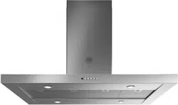
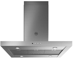
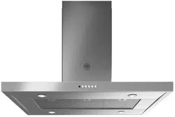
ISLAND T-SHAPE DESIGN HOODS
KTI..XT

2
CONTENTS
Section Page
IMPORTANT SAFETY INSTRUCTIONS 3
RANGE HOOD DIMENSIONS 6
INSTALLATION HEIGHT REQUIREMENTS 7
PARTS 8
TOOLS NEEDED 10
VENTING METHOD 11
COMPONENTS FOR INSTALLATION TO THE CEILING 12
INSTALLING 12
OPERATING THE CONTROLS
24
CLEANING STAINLESS STEEL
26
CARING FOR FILTERS
26
REPLACING ACTIVATED CHARCOAL FILTER
27
REPLACING BULBS
27
WIRING DIAGRAM
28
WARRANTY
29

3
IMPORTANT SAFETY INSTRUCTIONS
READ AND SAVE THESE INSTRUCTIONS BEFORE YOU START INSTALLING
THIS Range Hood
WARNING: - TO REDUCE THE RISK OF A RANGE TOP GREASE FIRE:
a) Never leave surface units unattended at high settings. Boilovers cause smoking and greasy
spillovers that may ignite. Heat oils slowly on low or medium setting.
b) AlwaysturnhoodONwhencookingathighheatorwhenambeingfood(i.e.CrepesSuzette,
CherriesJubilee,PeppercornBeefFlambé).
c) Cleanventilatingfansfrequently.Greaseshouldnotbeallowedtoaccumulateonfanorlter.
d)Useproperpansize.Alwaysusecookwareappropriateforthesizeofthesurfaceelement.
WARNING: - TO REDUCE THE RISK OF INJURY TO PERSONS IN THE EVENT OF A RANGE TOP
GREASEFIRE,OBSERVETHEFOLLOWING*:
a) SMOTHERFLAMESwithaclose-ttinglid,cookiesheet,ormetaltray,thenturnotheburner.
BECAREFULTOPREVENTBURNS.IftheamesdonotgooutimmediatelyEVACUATEAND
CALL THE FIRE DEPARTMENT.
b) NEVER PICK UP A FLAMING PAN - You may be burned.
c) DONOTUSEWATER,includingwetdishclothsortowels-aviolentsteamexplosionwillresult.
d) UseanextinguisherONLYif:
1. YouknowyouhaveaClassABCextinguisher,andyoualreadyknowhowtooperateit.
2. Thereissmallandcontainedintheareawhereitstarted.
3. Theredepartmentisbeingcalled.
4. Youcanghttherewithyourbacktoanexit.
* Based on "Kitchen Firesafety Tips" published by NFPA
WARNING-TOREDUCETHERISKOFFIREORELECTRICSHOCK,donotusethisfanwithany
solid-state speed control device.
WARNING-TOREDUCETHERISKOFFIRE,ELECTRICALSHOCK,ORINJURYTOPERSONS,
OBSERVE THE FOLLOWING:
1. Usethisunitonlyinthemannerintendedbythemanufacturer.Ifyouhaveanyquestions,
contact the manufacturer.
2. Beforeservicingorcleaningunit,switchpoweroatservicepanelandlocktheservicedi-
sconnecting means to prevent power from being switched on accidentally. When the service
disconnectingmeanscannotbelocked,securelyfastenaprominentwarningdevice,such
asatag,totheservicepanel.
CAUTION:ForGeneralVentilatingUseOnly.DoNotUseToExhaustHazardousorExplosive
Materials and Vapors.
WARNING-TOREDUCETHERISKOFFIRE,ELECTRICALSHOCK,ORINJURYTOPERSONS,
OBSERVE THE FOLLOWING:
1. InstallationWorkAndElectricalWiringMustBeDoneByQualiedPerson(s)InAccordance
WithAllApplicableCodesAndStandards,IncludingFire-RatedConstruction.
2. Sucientair isneeded for proper combustion and exhausting of gases through the ue
(chimney)offuelburningequipmenttopreventbackdrafting.Followtheheatingequipment
manufacturer's guideline and safety standards such as those published by the National Fire
ProtectionAssociation(NFPA),andtheAmericanSocietyforHeating,RefrigerationandAir
ConditioningEngineers(ASHRAE),andthelocalcodeauthorities.
3. Whencuttingordrillingintowallorceiling,donotdamageelectricalwiringandotherhidden
utilities.
4. Ducted fans must always be vented to the outdoors.
4
ALL WALL AND FLOOR OPENINGS WHERE THE Range Hood IS INSTALLED MUST BE
SEALED.
This Range Hood requires at least 24" of clearance between the bottom of the Range Hood and the
cooking surface or countertop. This hood has been approved by UL at this distance from the cooktop.
This minimum clearance may be higher depending on local building codes. For gas cooktops and
combination ranges, a minimum of 30" is recommended and may be required.
Overhead cabinets on both sides of this unit must be a minimum of 18" above the cooking surface
or countertop. Consult the cooktop or range installation instructions given by the manufacturer before
making any cutouts.
MOBILE HOME INSTALLATION The installation of this Range Hood must conform to the Manufactured
Home Construction and Safety Standards, Title 24 CFR, Part 3280 (formerly Federal Standard for Mobile
Home Construction and Safety, Title 24, HUD, Part 280). See Electrical Requirements"
• Venting system MUST terminate outside the home.
• DO NOT terminate the ductwork in an attic or other enclosed space.
• DO NOT use 4" laundry-type wall caps.
• Flexible-type ductwork is not recommended.
• DO NOT obstruct the ow of combustion and ventilation air.
• Failure to follow venting requirements may result in a re.
WARNING
!
VENTING REQUIREMENTS
Determine which venting method is best for your application. Ductwork can extend either through the
wall or the roof.
The length of the ductwork and the number of elbows should be kept to a minimum to provide ecient
performance. The size of the ductwork should be uniform. Do not install two elbows together. Use duct
tape to seal all joints in the ductwork system. Use caulking to seal exterior wall or oor opening around
the cap.
Flexibleductworkisnotrecommended.Flexibleductworkcreatesbackpressureandairturbu-
lence that greatly reduces performance.
Make sure there is proper clearance within the wall or oor for exhaust duct before making cutouts. Do
not cut a joist or stud unless absolutely necessary. If a joist or stud must be cut, then a supporting frame
must be constructed.
WARNING-ToReduceTheRiskOfFire,UseOnlyMetalDuctwork.
CAUTION-Toreduceriskofreandtoproperlyexhaustair,besuretoductairoutside–Do
notventexhaustairintospaceswithinwallsorceilingsorintoattics,crawlspaces,orgarages.
Cold Weather installations
An additional back draft damper should be installed to minimize backward cold air ow and a nonmetallic thermal
break should be installed to minimize conduction of outside temperatures as part of the vent system. The damper
should be on the cold air side of the thermal break. The break should be as close as possible to where the vent
system enters the heated portion of the house.
5
ELECTRICAL REQUIREMENTS
A 120 volt, 60 Hz AC-only electrical supply is required on a separate 15 amp fused circuit. A time-delay
fuse or circuit breaker is recommended. The fuse must be sized per local codes in accordance with
the electrical rating of this unit as specied on the serial/rating plate located inside the unit near the
eld wiring compartment.
• Electrical ground is required on this Range Hood.
• If cold water pipe is interrupted by plastic, nonmetallic gaskets or other materials, DO
NOT use for grounding.
• DO NOT ground to a gas pipe.
• DO NOT have a fuse in the neutral or grounding circuit. A fuse in the neutral or
grounding circuit could result in electrical shock.
• Check with a qualied electrician if you are in doubt as to whether the Range Hood is
properly grounded.
• Failure to follow electrical requirements may result in a re.
WARNING
!
StateofCaliforniaProposition65Warning(USonly)
WARNING
This product contains chemicals known to the State of California to cause cancer and birth
defects or other reproductive harm.
For more information go to www.P65Warnings.ca.gov
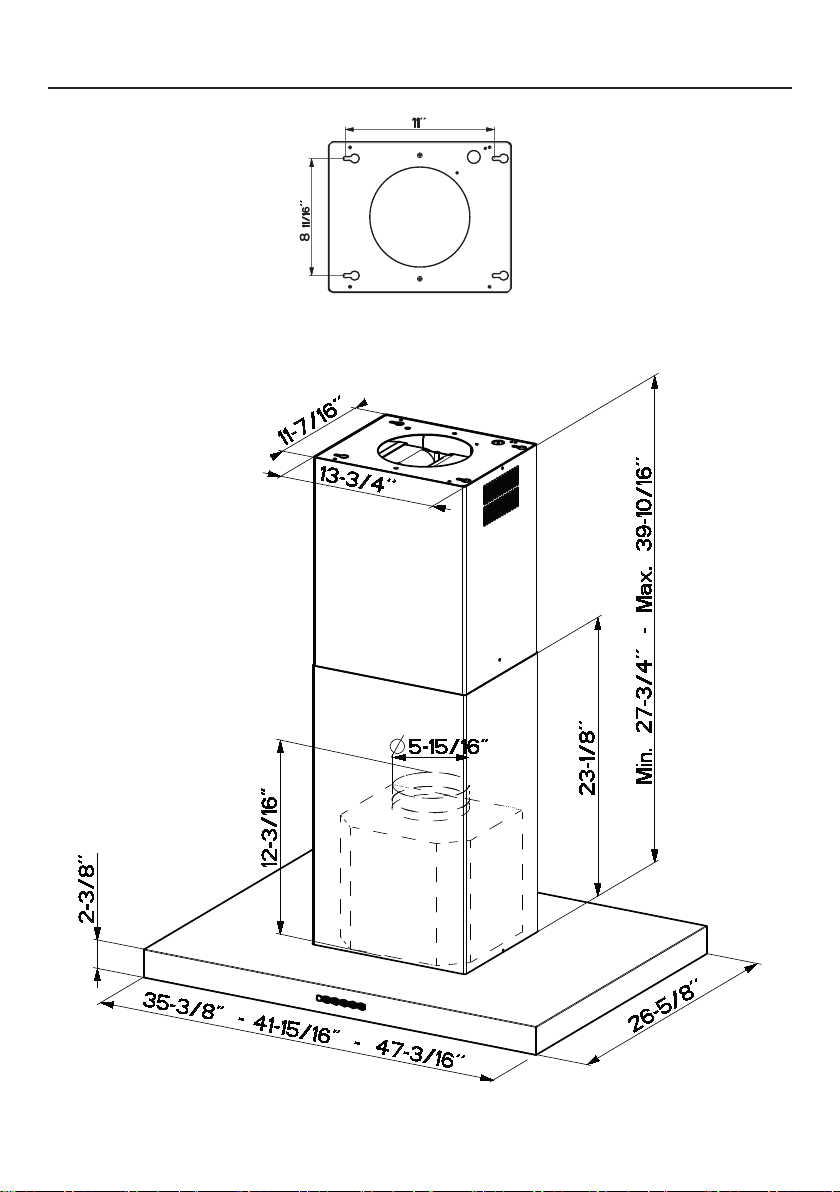
6
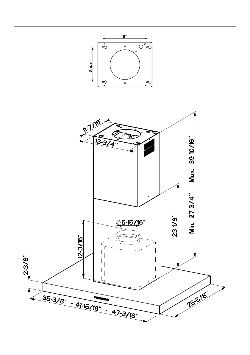
RANGE HOOD DIMENSIONS
0LQ´
0D[´
0LQ´
0D[´
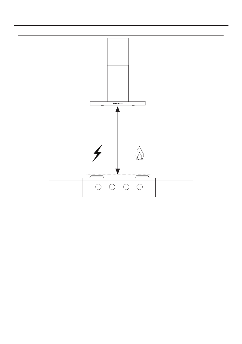
7
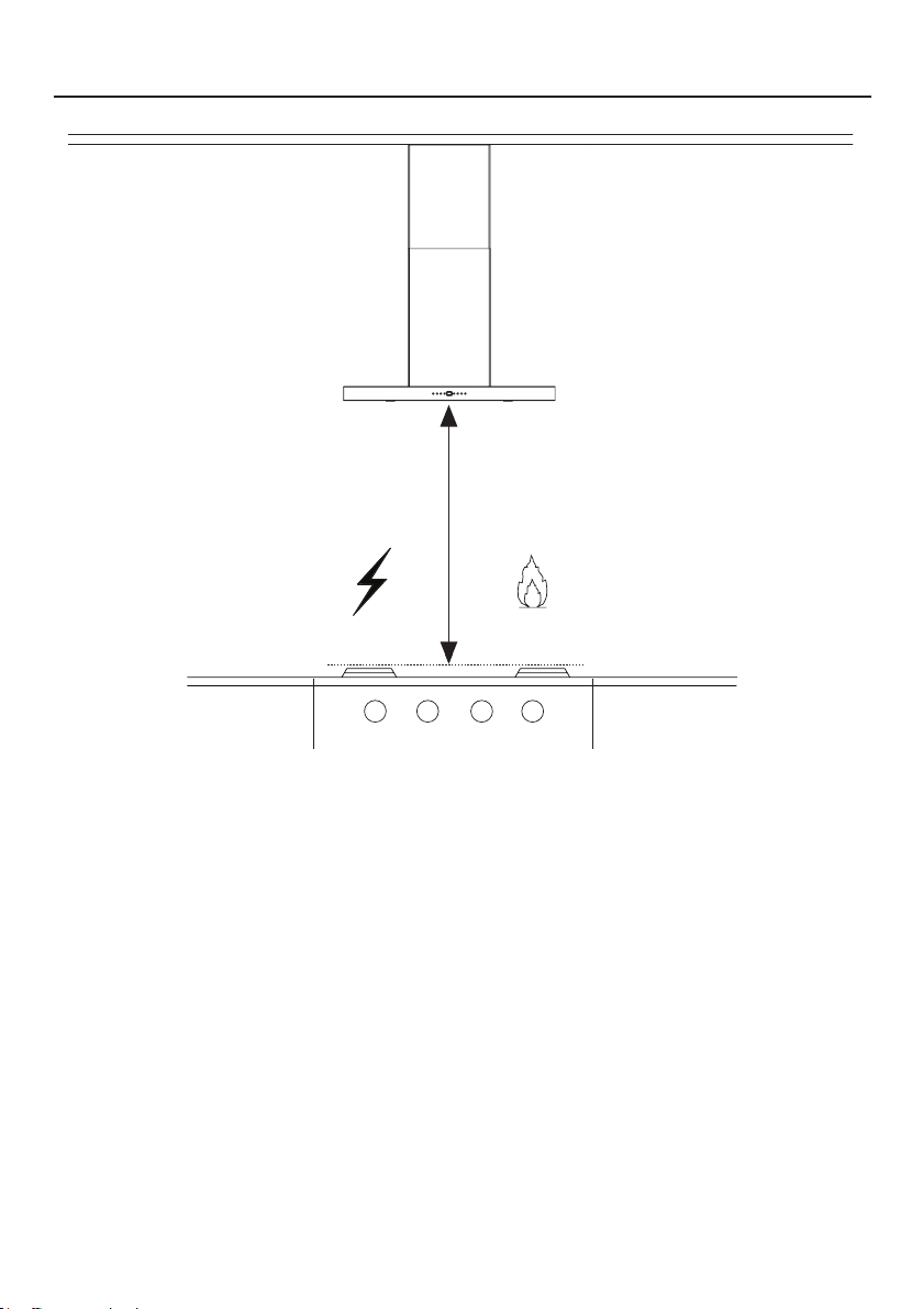
INSTALLATION HEIGHT REQUIREMENTS
MIN. 24" OVER ELECTRIC
MIN. 30" OVER GAS
Min. 24" Min. 30"
8
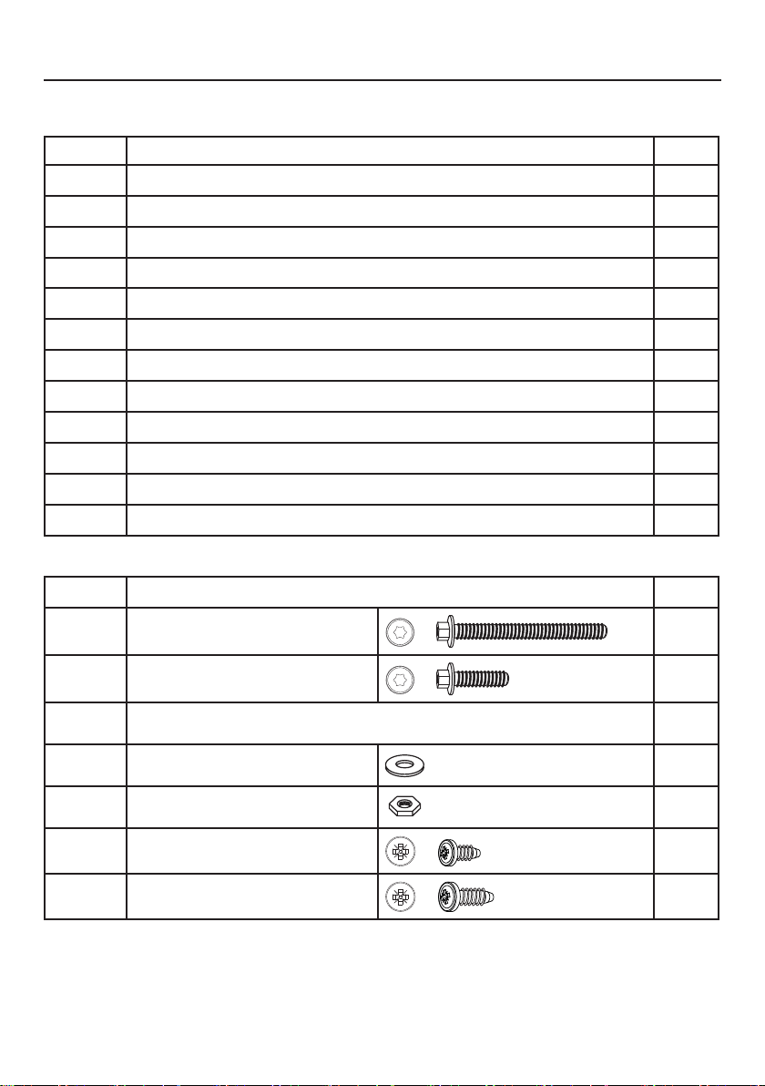
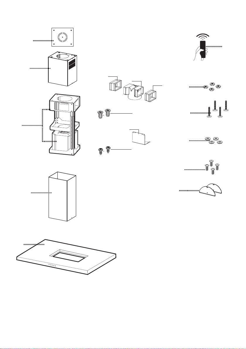
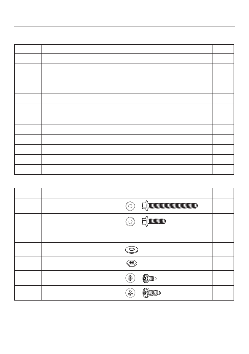
PARTS
REF. PART
QTY
1
Hood body
1
2
Telescopic Chimney comprising:
1
2.1
Upper Section
1
2.2
Lower Section
1
7.1
Telescopic frame complete with extractor, consisting of:
1
7.1a
Upper frame
1
7.1b
Lower frame 1
10
Flaps 2
25
Remote control 1
T1-T3
Air Outlet Connector Extension 2
T2
Air Outlet Connector 1
T4
Air Outlet Connector xing bracket 1
REF
PART
12q
Torx Screws 1/4" x 3 1/8"
4
12f
Torx Screws 1/4" x 9/16"
4
21
Drilling template
1
22
1/4" int. dia washers
4
23
1/4" Nuts
4
A2
Pozi Screws 1/8" x 1/4"
2
A3
Pozi Screws 1/8" x 3/8"
2
PARTS INCLUDED
9
A3
2x
(2,9x9,5)
A2
2x
(2,9x6,5)
10
1
2.2
21
7.1
12f
22
12q
7.1a
7.1b
23
25
T1
T2
T3
T4
2.1
10
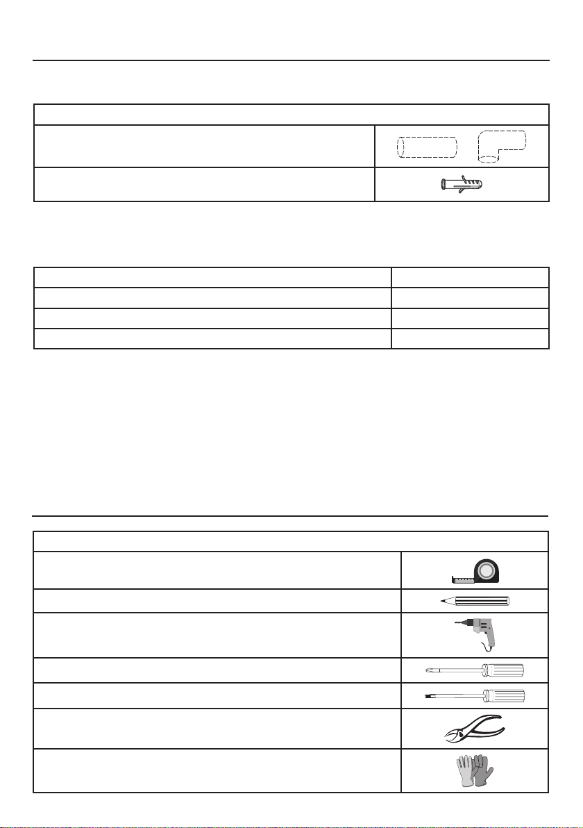
PARTS NEEDED
PARTS(cont.)
PART
6" Round Metal Ductwork
Drywall plugs or other suitable wall fasteners based on your instal-
lation.
TOOLS NEEDED
TOOL
Tape Measure
Pencil
Electric Drill with 5/16" Drill Bit
Phillips Screwdriver
Torx Screwdriver
Metal sheers
Work gloves
ACCESSORIES AVAILABLE
ACCESSORY
SKU#
Replacement Activated Charcoal Filter # 901497
Bae lter Kit # 901581
Duct cover kit installation up to 10' # 901585

11
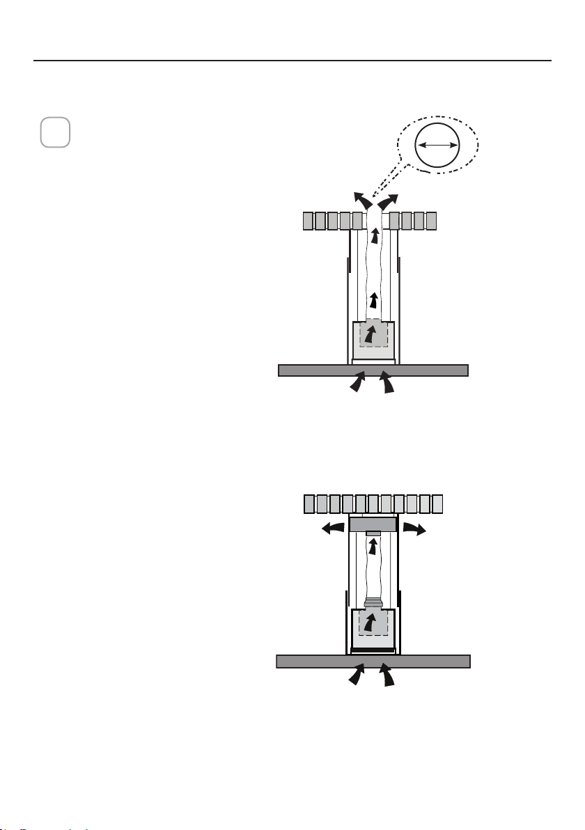
VENTING METHOD
Ducted Venting Installation
Non ducted - recirculation
1
Requires purchase of
Activated Charcoal
Accessory kit.
6 "

12
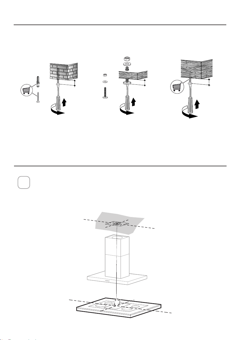
COMPONENTS FOR INSTALLATION TO THE CEILING
T
OK!
3/16 ”
OK!
3/16 ”
These fasteners may need to be purchased separately depending on your installation.
INSTALLING
Do not make any cutouts until you have decided whether this installation will be
ducted or non-duct and then plan accordingly.
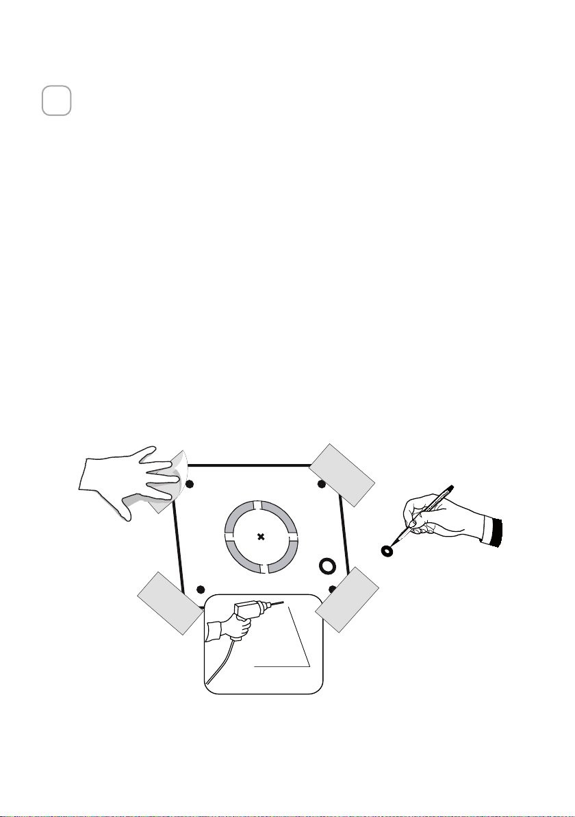
1
K
OK!
3/16 ”
13
Put a thick, protective covering over cooktop,
set-in range or countertop to protect from damage or dirt.
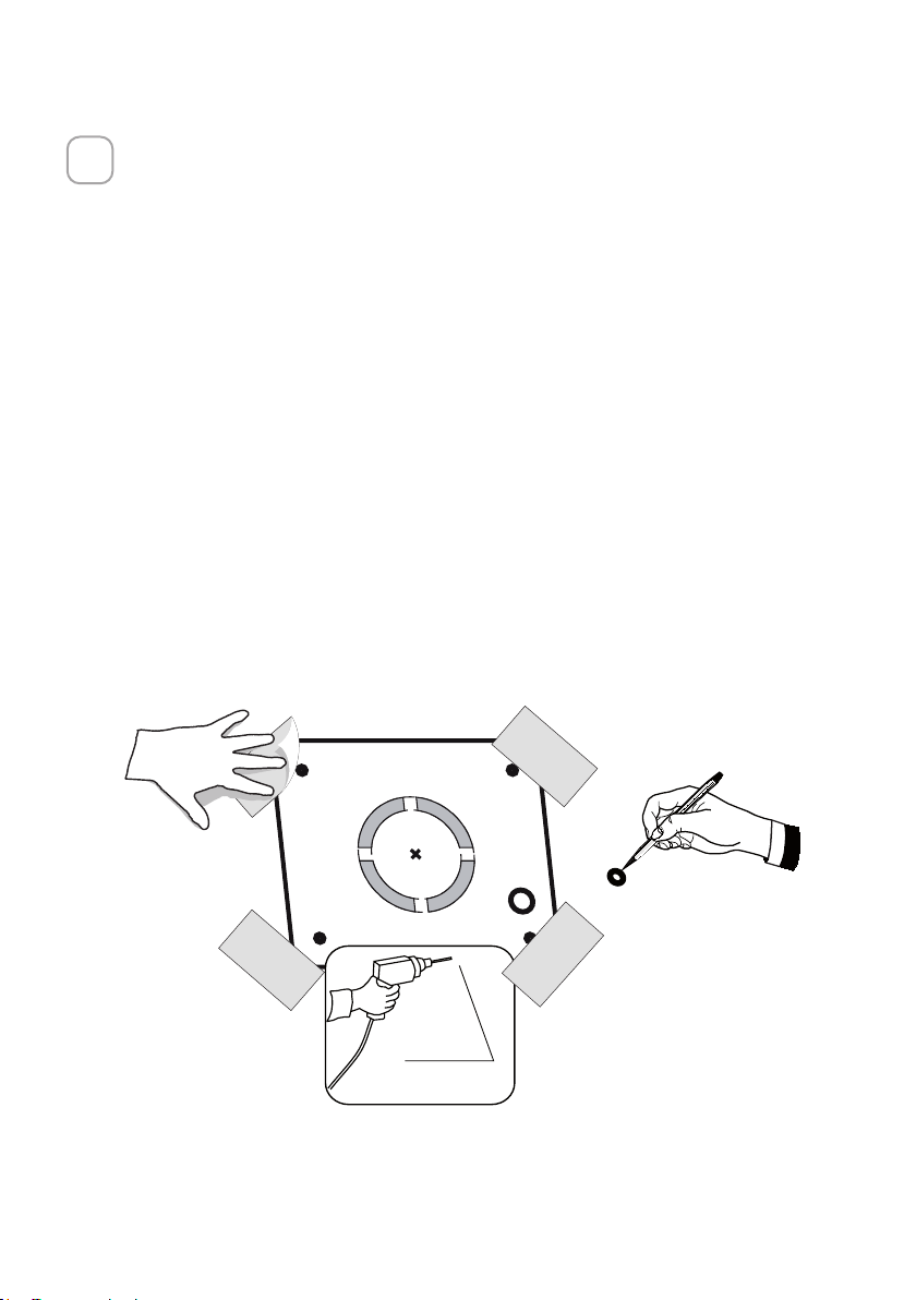
Determine and clearly mark with a pencil on the ceiling where the rangehood will
be installed.
A template 21 for mounting the support is supplied in the carton with the support.
Use this template to mark holes for
support on the ceiling.
Determine and make necessary cuts for the ductwork. The duct opening is shown
on the mounting template. Install
ductwork before mounting the hood.
Determine the proper location for the Power Supply Cable as indicated on the
template. Use a 1 1/4" Drill Bit to make this hole. Run the Power Supply Cable.
Use caulking to seal around the hole.
A knockout for threading through the Power Supply from the ceiling is located on
the top of the frame. Do not connect the Power Cable to the Wiring Box or power
up the hood at this time. Run enough power cable from the ceiling to reach the
wiring box on the hood.
2
Ø 10 mm
x4
21
1 1/4"
14
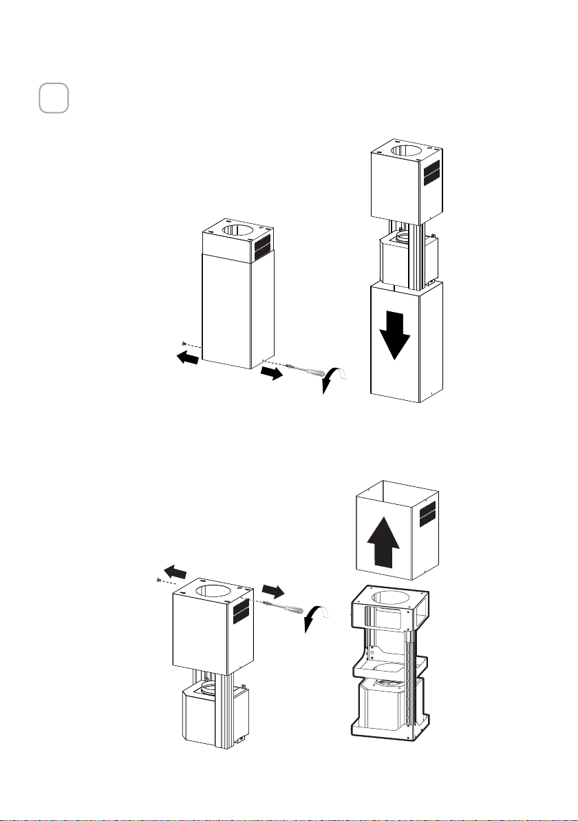
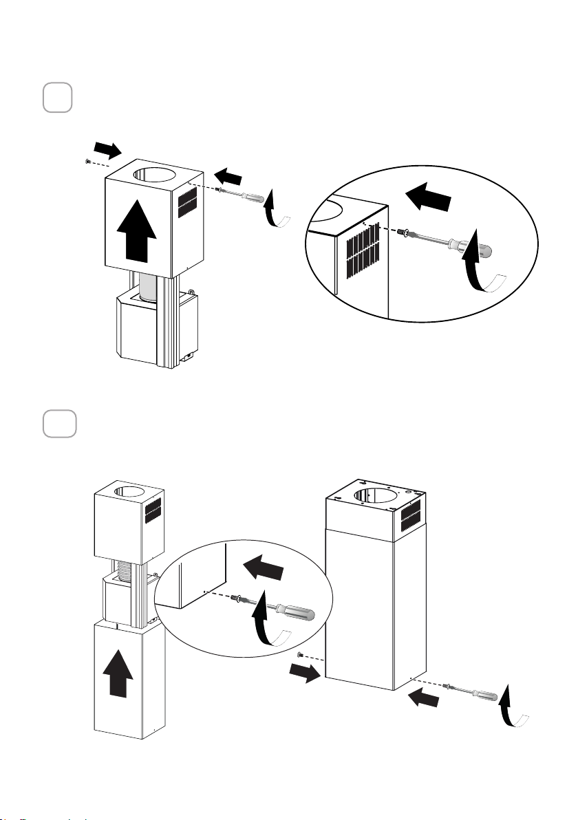
3
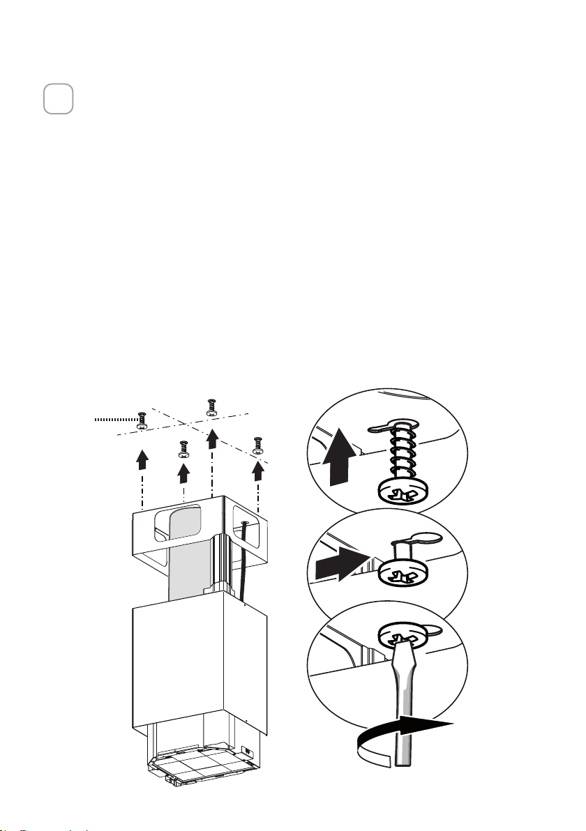
Chimney Flues Must Be Removed Before Installing the Hood
Loosen the two screws fastening the lower chimney and remove this from the lower frame.
Loosen the two screws fastening the upper chimney and remove this from the upper frame.
15
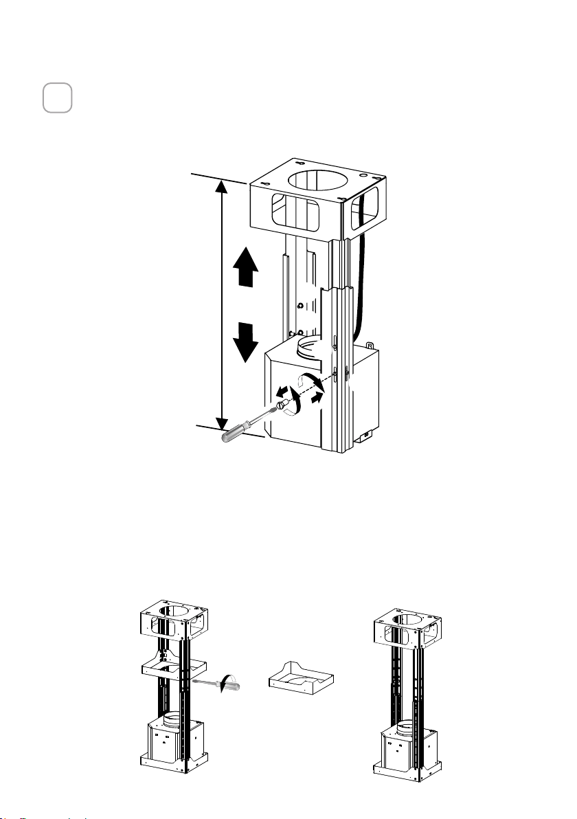
4
If you need to adjust the height of the frame, proceed as follows:
• Unfasten the metric screws joining the two columns, located at the sides of the frame
(1,2,3,4,5,6).
• Adjust the frame to the height required, then ret all the screws removed as above.
NOTE: The chimney structure can reduce down to a 27 " minimum height. To
reduce the height, the middle section of the support structure needs to be removed.
Out of the box, the minimum chimney length is 32 ". Insure the the installation
process outlined in the U&C is followed and there is sucient stability with the
middle section removed.
REMOVING THE MIDDLE TRESTLE COMPONENT
4 REMOVING THE MIDDLE TRESTLE COMPONENT
Insure the the installation process outlined in the U&C is followed and there is sufficient stability with the
middle section removed.
16
5
6
Upper Flue Must Be In Place Before Proceeding
After the regulation for height adjustment, insert the upper
chimney stack from above, and leave it running free on the
frame.
Only for Ducted Venting Installation
Install the Flaps included 10 with the Hood
before connecting to the ductwork.
10

17
7
Now take either your wood screws or bolts depending on your set-up and screw all four
into the pilot holes and leave 1/4" of the heads exposed.
Next install a UL or CSA listed strain relief in the wiring box so that the screws can be
tightened after the chimney support is attached to the ceiling.
Now lift the chimney support into it's nal position and feed the electrical supply through
the strain relief.
Next position the chimney support so that the large end of the keyhole slots are over
the ceiling attachment screws or bolts. Then push the chimney support so that the bolts
are in the neck of the slots. Tighten all four screws or bolts securely.
• The frame mountings must be secure to withstand the weight of the hood and any
stresses caused by the occasional side thrust applied to the device. On completion,
check that the base is stable, even if the frame is subjected to bending.
• In all cases where the ceiling is not strong enough at the suspension point, the installer
must provide strengthening using suitable plates and backing pieces anchored to the
structurally sound parts.
12q
18
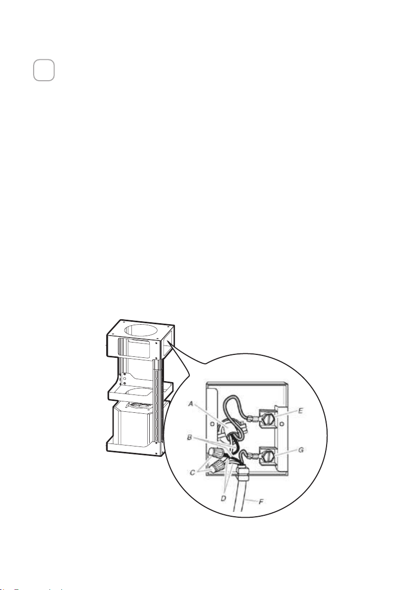
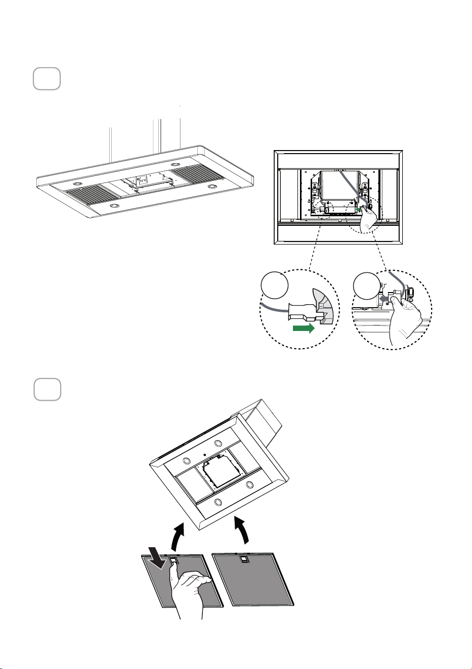
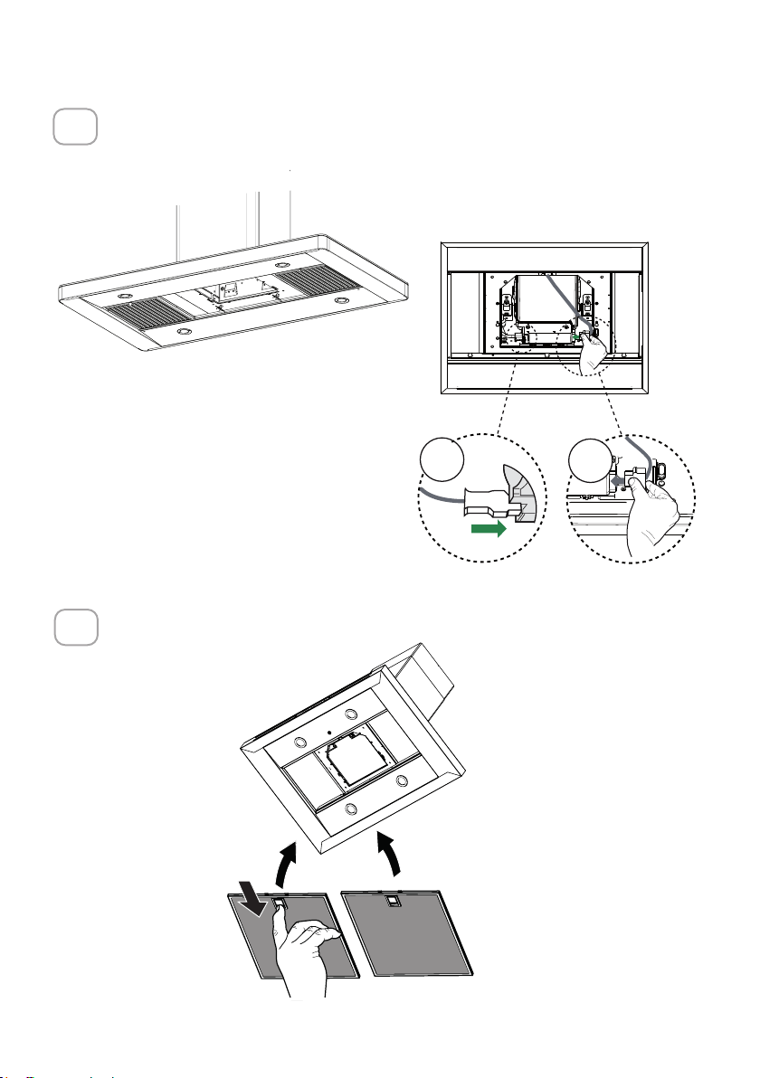
8
Installation of wiring connection
Remove the cover from the eld wiring compartment.
DO NOT turn on the power until installation is complete!
Connect the Power Supply Cable to the rangehood.
Connect the Green (Green and Yellow) ground wire under the Green grounding
screw. Attach the White lead of the power supply to the White lead of the rangehood
with a twist-on type wire connector.
Attach the Black lead of the power supply to the Black lead of the rangehood with a
twist-on type wire connector.
Replace the eld wiring compartment cover and the grease lters.
A. Home power supply cable
B. Black wires
C. UL listed wire connectors
D. White wires
E.Green(orbare)groundwirefromhomepowersupplyconnectedtogreengroundscrew
F. Range hood power supply cable
G. Range hood power supply cable connected to green ground screw
Remove the cover from the eld wiring compartment.
Connect the Power Supply Cable to the rangehood.
Connect the Green (Green and Yellow) ground wire under the
wire connector. Attach the Black lead of the power supply
to the Black lead of the rangehood with a twist-on type wire
The UPPER CHIMNEY
COVER
, use the UPPER
CHIMNEY COVER supplied
attach the UPPER CHIMNEY
COVER.
Make sure to seal all joints with
The LOWER CHIMNEY
COVER
Install the LOWER CHIMNEY
COVER by sliding it up over
the support and the UPPER
CHIMNEY COVER.
For ductless installations, line up the DUCTLESS DIVERTER
EXTENSIONS HORIZONTAL
in the LOWER CHIMNEY COVER
B. Black wires
C. UL listed wire connectors
CHIMNEY COVER
, place the DUCTLESS
exhaust opening of the EASY
CUBE . Fit the DUCTLESS
DIVERTER EXTENSIONS
HORIZONTAL
19
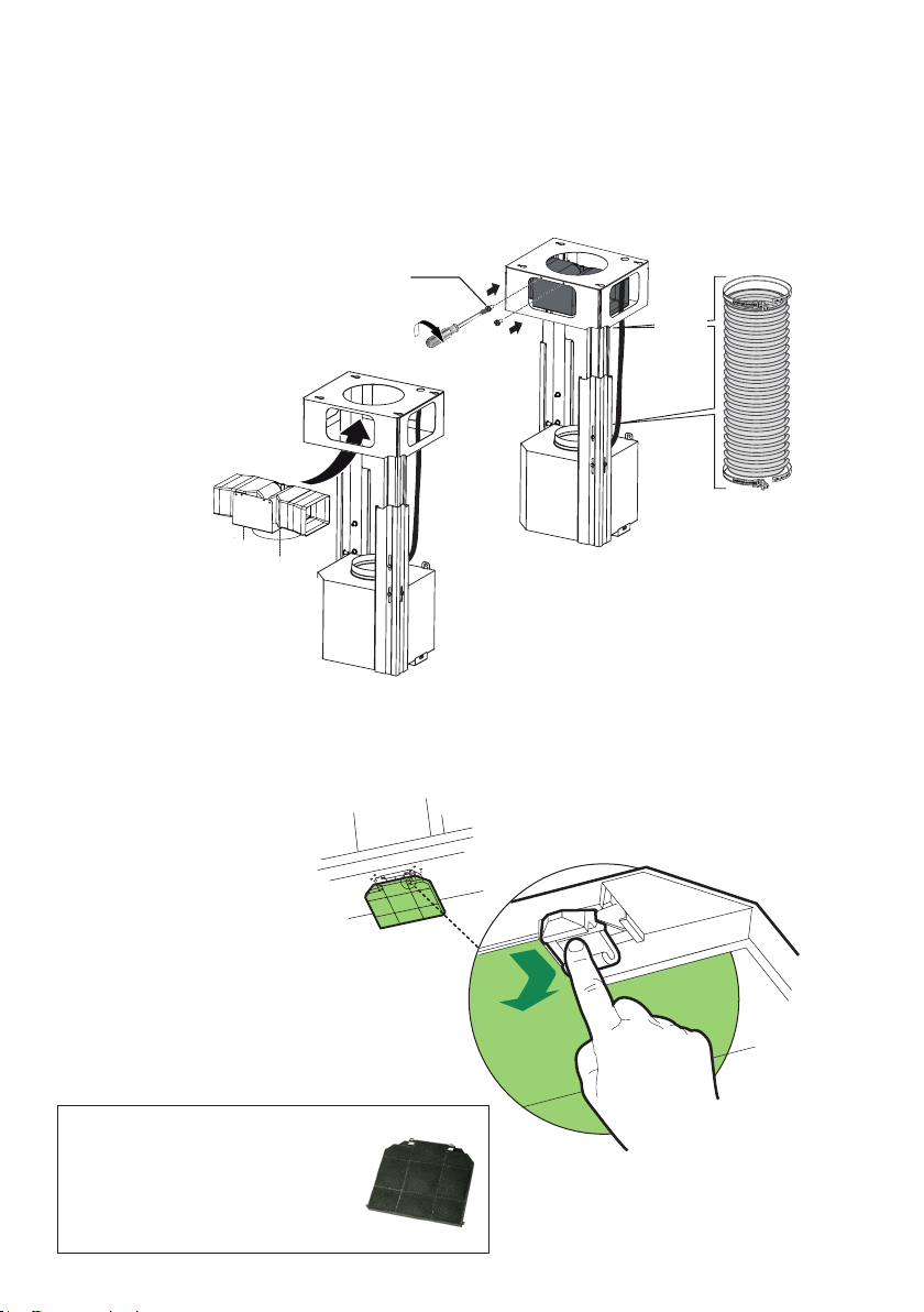
9
Position the upper chimney section and x the upper part to the frame using
the 2 screws removed previously.
10
Similarly, position the lower chimney section and x the lower part to the frame
using the 2 screws removed previously.

20
11
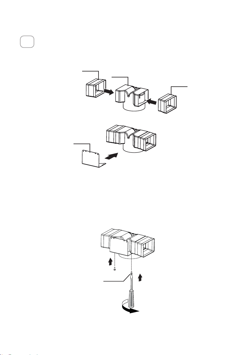
Only for non ducted recirculating installations
Insert the Connector extensions T1 and T3 into the side of the Connector T2.
Insert the Connector T2 into the Support bracket T4 and x it with the screws.
1
2
T1
T2
T3
T4
A3
2x
Fasten the Support bracket T4 xing it to the upper part with the Screws.

21
Make sure that the Connector extensions outlet T1 and T3 is in correspondence with the Chimney
openings both horizontally and vertically.
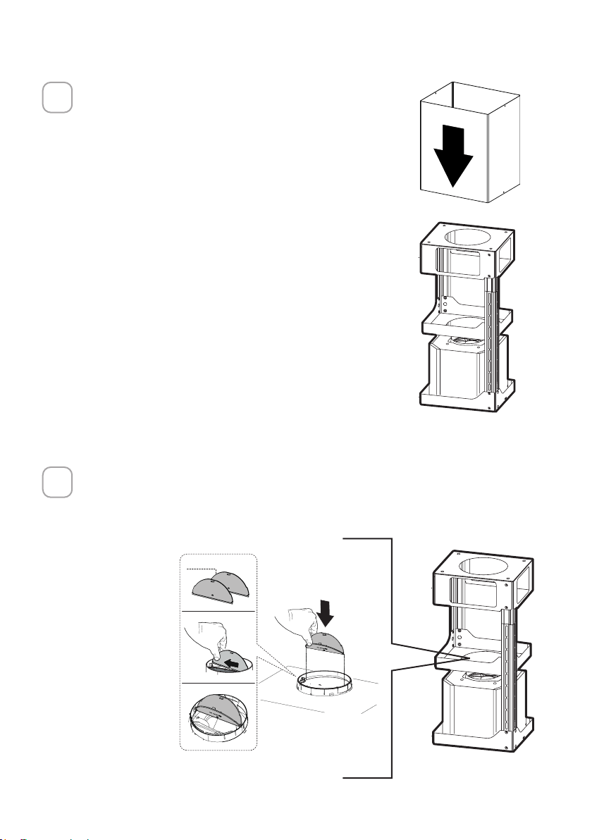
Attach a charcoal lter in the correct position and block it by the xing hooks as
$
[
$
[
shown. Unlock the xing hooks (towards the back of the hood) to remove.
Required Activated Charcoal
Filter Accessory - sku # 901497
(purchased separately)

22
12
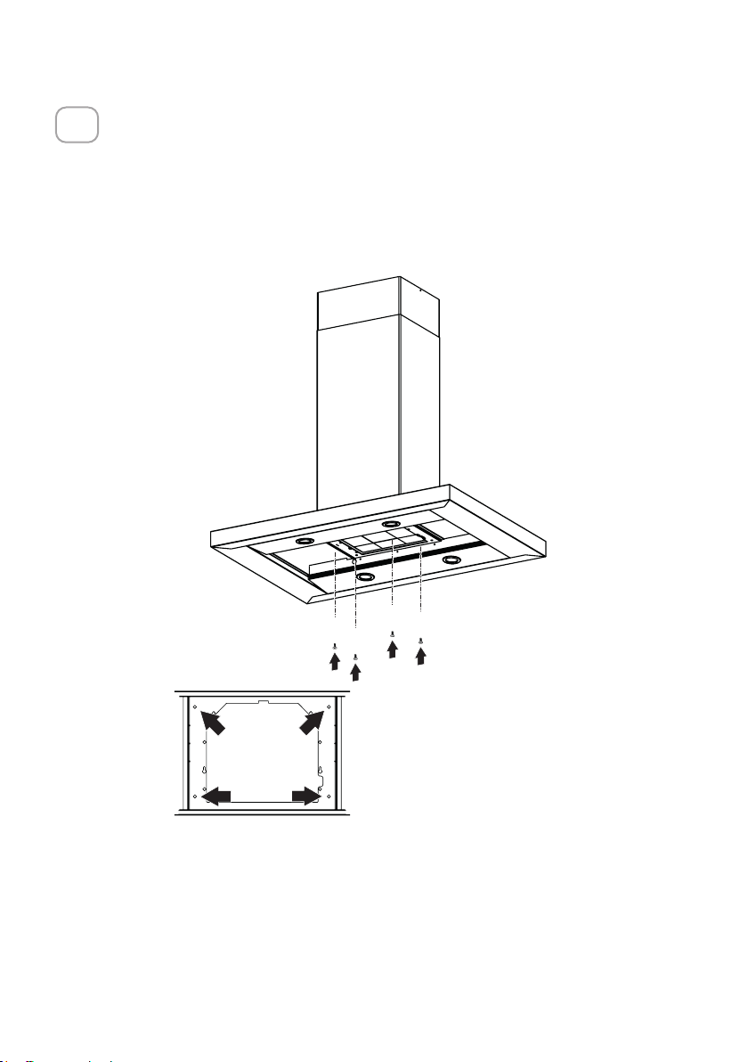
Attachment of Hood Canopy
Remove the grease lters from the hood canopy.
Remove any activated charcoal lters.
Working from below, x the hood canopy to the frame where indicated, using the 4
screws 12f, then tighten all the screws securely.
I
[
23
13
Connect the connector "B".
Check the connection of connector "A".
14
Reinstall the grease lters from the hood canopy.
A
B
24
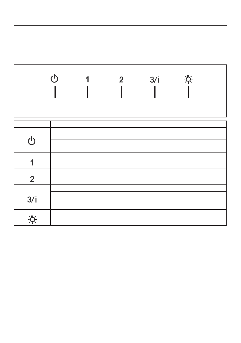
OPERATING THE CONTROLS
FOR BEST RESULTS
Start the Range Hood several minutes before cooking to develop proper airow.
Allow the Range Hood to operate for several minutes after cooking is complete to
clear all smoke and odors from the kitchen.
NOTE: If your product has had a CFM adjustment, refer to the CFM adjustment manual for the information.
Some motor speeds or functions may be reduced.
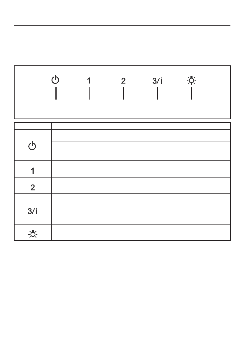
Button Function
Fan o button:turn the blower O. The fan can be operated by pressing any of the fan
setting buttons.
Hold down this button for 2 seconds to activate Delay o function which will keep the fan on
for 15 minutes and automatically shut o.
Fan settings buttons: Low speed.
Fan settings buttons: Medium speed.
Fan settings buttons: High speed / Intensive speed.
Hold down the button for 2 seconds to activate the intensive speed, which is timed to run
for 6 minutes. At the end of this time it will automatically return to the speed set before.
Suitable to deal with maximum levels of cooking fumes.
Light button: On/O switch for the lights.
LT1 T2 T3 T4

25
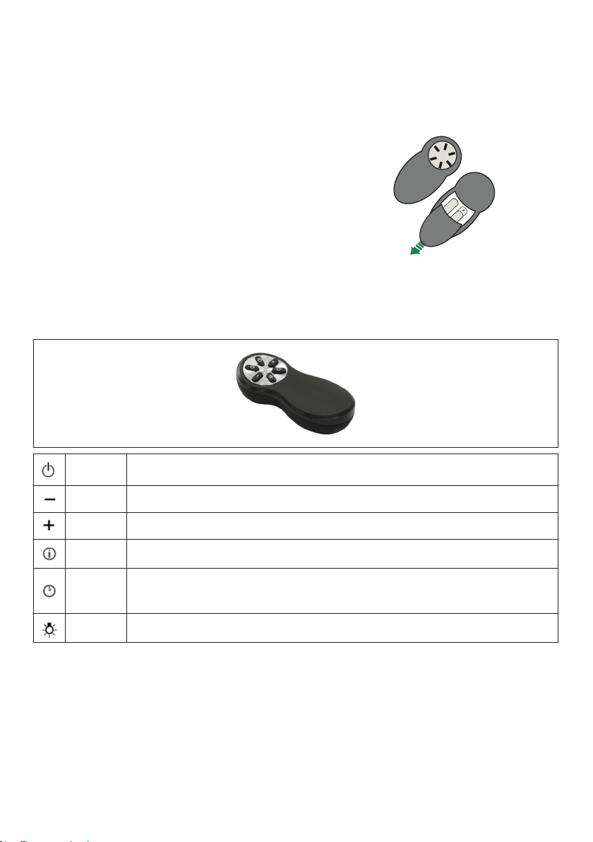
Remote control information
The appliance can be controlled using a remote control powered by a 1.5 V carbon-zinc
alkaline batteries of the standard LR03-AAA type (not included).
• Used batteries must be disposed of in the proper manner.
Caution:
• Do not place the remote control near heat
sources.
• Do not discard the batteries with normal waste,
they must be put into the specic containers.
• Make sure the battery compartment is screwed
down at and is fully tightened.
Remote Control control panel
Motor Motor On/O.
- Decreases the working speed each time it is pressed.
- Increases the working speed each time it is pressed.
Intensive Activates/Deactivates Intensive operation.
Delay
Brief pressure: Activates/Deactivates the Delay function: automatic switch-o with
a 30’ delay. The display shows the operating speed and the dot at the bottom right
ashes once a second.
Light Lights On / O.

26
CleaningExteriorsurfaces:
Please note, abrasives and scouring agents can scratch range hood nishes and should
not be used to clean nished surfaces.
StainlessSteelnishcleaninginstructions:
Clean exterior surfaces with a commercially available stainless steel cleaner.
Use a soft microber cloth and to wipe going with the grain of the stainless steel.
CLEANING STAINLESS STEEL
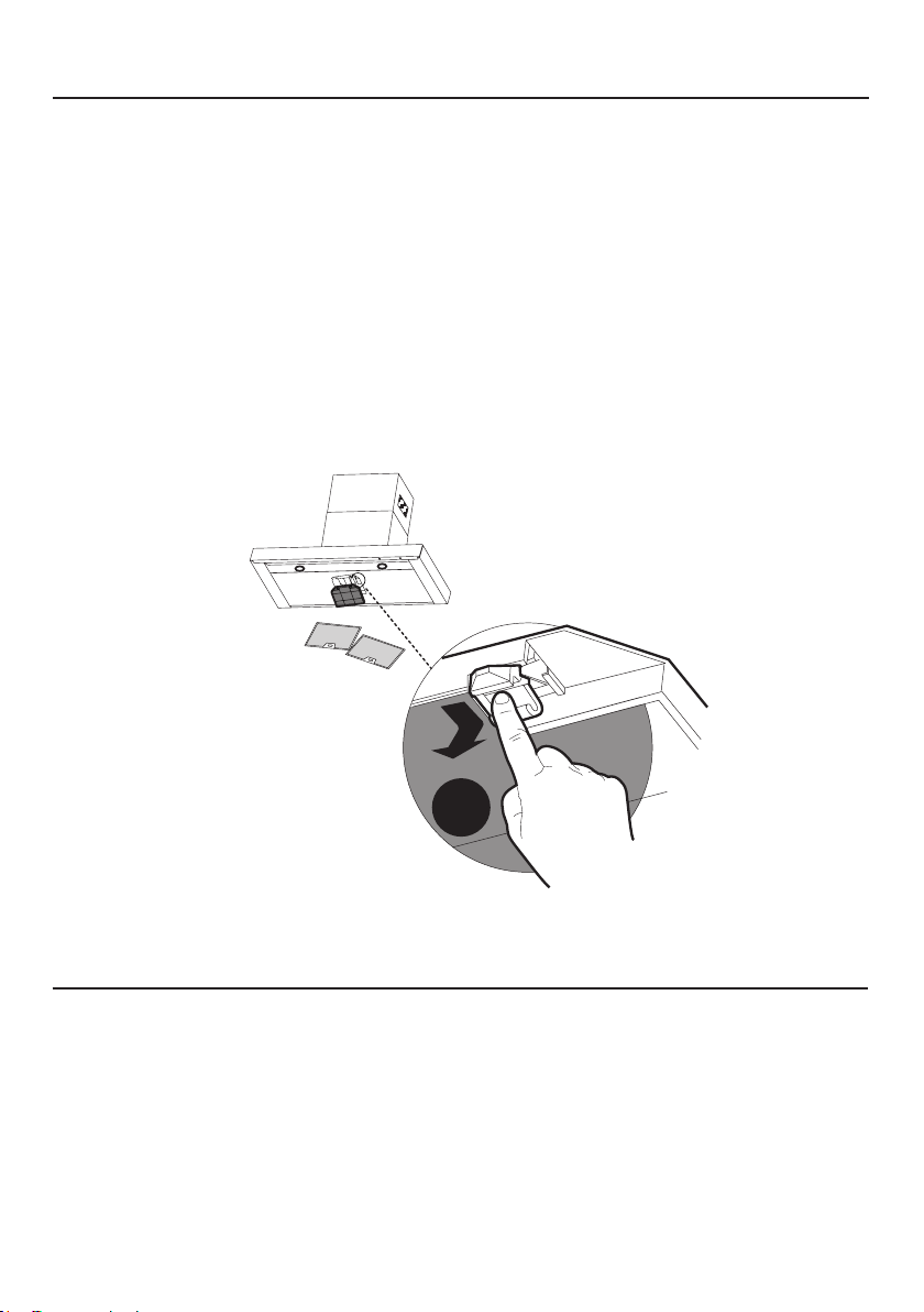
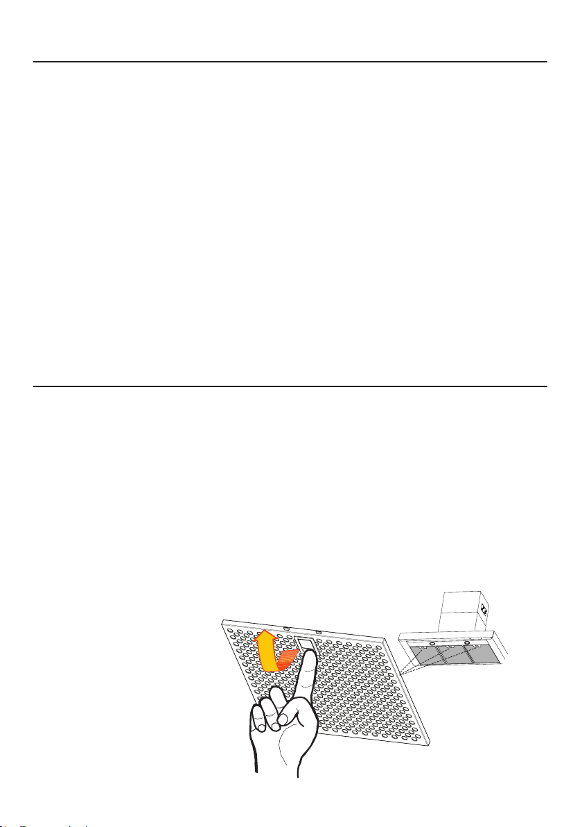
CARING FOR FILTERS
CLEANING METAL GREASE FILTERS
The lters must be cleaned every 2 months of operation, or more frequently for particularly
heavy usage, and can be washed in a dishwasher.
• Remove the Filters one at a time, pushing them towards the back of the unit and at
the same time pulling downward.
• Wash the Filters without bending them, and leave them to dry completely before
replacing. (If the surface of the lter changes colour as time goes by, this will have
absolutely no eect on the eciency of the lter itself.)
• Replace, taking care to ensure that the handle faces forwards.
• No water can be present in lters before installing back in hood.
27
REPLACING BULBS
LEDlightsmustbereplacedbyauthorizedservice.
REPLACING ACTIVATED CHARCOAL FILTER
• Remove the Filters one at a time, pushing them towards the back of the unit and at the same
time pulling downward.
• Remove the saturated charcoal lter by releasing the hooks.
• Fit the new lter and fasten it in its correct position.
• Replace, taking care to ensure that the handle faces forwards.
• "When used in recirculation mode, to Reduce the Risk of Fire and Shock use only conver-
sion kit Model # 901497.
Please contact the retailer that sold you the product to purchase carbon lters above.
W
The lter is not washable and cannot be regenerated, and must be replaced approximately
every 4 months of operation, or more frequently for particularly heavy usage.
28
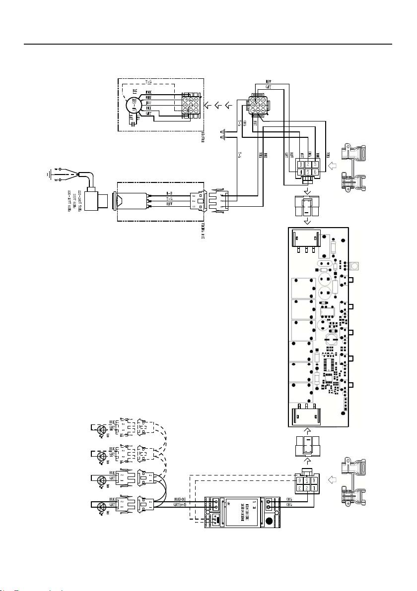
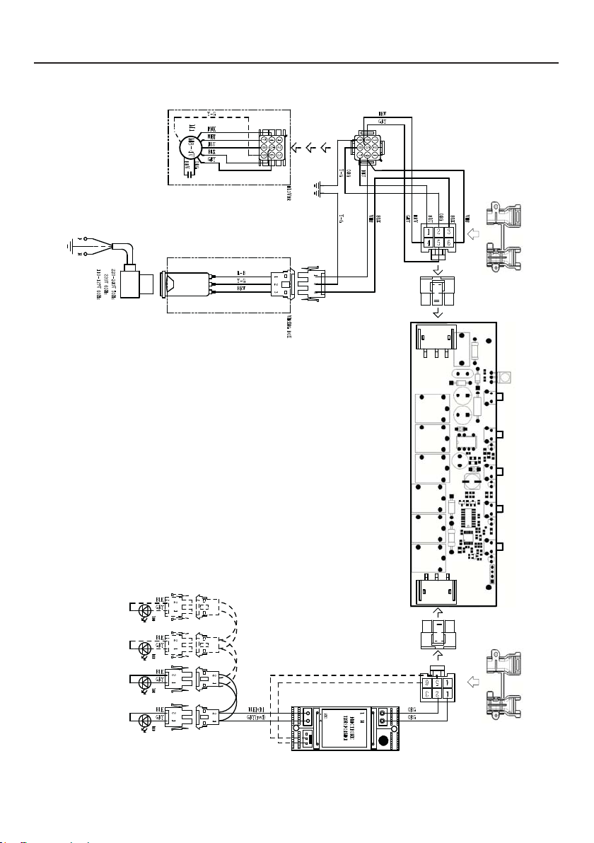
WIRING DIAGRAM

29
WARRANTY
25
Please kindly register on our web site www.bertazzoni.com to validate your new product warranty
and help us to assist you better in case of any inconvenience.
TWO YEAR LIMITED WARRANTY
Thewarranties provided by BertazzoniSpa inthisstatement apply exclusivelyto Bertazzoniappliancesand
accessories sold as new products to the original owner by a Bertazzoni authorized distributor, retailer, dealer or
service center and installed in the United States and Canada. The warranties provided in this statement are
not transferable and have validity from the date of installation.
COVERAGE INFORMATION
Bertazzoni SpA will repair or replace any component part which fails or proves defective due to materials and/or
workmanship within 2 years from the date of installation and under conditions of normal residential use. Repair
or replacement will be free of charge, including labor at standard rates and shipping expenses. Repair service
must be performed by a Bertazzoni Authorized Service
Center during normal working hours.
COSMETIC WARRANTY
Bertazzoni will cover parts showing cosmetic defects in material and workmanship for a period of thirty (30) days
from date of installation of the unit. This coverage will include scratches, stains, surface imperfections on
stainless steel, paint and porcelain, with the exclusion of slight differences in color due to materials and
painting/enamelling technologies.
Exclusions are labor costs, B stock items, out‐of‐box appliances and display units.
HOW TO
OBTAIN SERVICE
To obtain service please contact Bertazzoni Customer Service at the numbers below and make sure to
have model number, serial number, and date of purchase ready. This information will be requested by our
team and is crucial to speeding up resolution.
UNITED STATES https://us.bertazzoni.com/more/support
Phone: 866-905-0010
CANADA https://ca.bertazzoni.com/more/support
Phone : 800-361-0799
Save proof of original purchase or of original installation to establish warranty period. Copy of the product serial
tag is affixed to the back cover of the instruction manual.
WHAT IS NOT COVERED
1.The product used in any commercial/business application
2.Repair service provided by other than a Bertazzoni authorized service agent.
3.Damage or repair service to correct service provided by an unauthorized agency or the use of
unauthorized parts.
4.Installation not in accordance with local electrical codes or plumbing codes.
5.Defects or damage due to improper storage of the product.
6. Defects or damage or missing parts on products sold out of the original factory packaging or from
displays.
7. Service calls or repairs to correct the installation of the product and/or related accessories.
8. Service calls to connect, convert or otherwise repair the electrical wiring / gas line / water line to
properly use the product.
9. Service calls to provide instructions on the use of a Bertazzoni product.
10. Repair service due to product usage in manner other than what is normal and customary for home use.
11. Replacement of wear and tear parts
12. Replacement of glasses andlight bulbs if they are claimed to have failed later than 30 days
after installation and in no case later than 4 months after
date of purchase
13. Defects and damages arisingfrom accident, alteration, misuse,abuse, improper installation.
14. Defects and damages arising from transportation of the product to the home of the owner.
15. Defects and damage arising from external forces beyond the control of Bertazzoni SpA such
as fire, flood, earthquakes and other acts of God.
In case the product will be installed in a remote area, where certified trained technicians are not
reasonably available, the customer will be responsible for the transportation costs for the
delivery of the product to the nearest authorized service center or for the displacement costs of a
certified trained technician.
Bertazzoni does not assume any responsibility for incidental or consequential damages.
Some states do not allow the exclusion or limitation of incidental or consequential damages, so the
above limitation or exclusion may not apply to you. This warranty gives you specific legal rights and you may also
have other rights which may vary from state to state or province to province.

30
TABLE DES MATIÈRES
Section Page
CONSIGNES DE SÉCURITÉ IMPORTANTES 31
DIMENSIONS DE LA HOTTE 34
EXIGENCE D’INSTALLATION EN HAUTEUR 35
PIÈCES 36
OUTILS NÉCESSAIRES 38
MÉTHODE D'AÉRATION 39
COMPOSANTS POUR L'INSTALLATION AU PLAFOND 40
INSTALLATION 40
FONCTIONNEMENT DES COMMANDES 52
NETTOYAGE DE L'ACIER INOXYDABLE 54
ENTRETIEN DES FILTRES
54
REPLACEMENT FILTRE À CHARBONS ACTIFS
55
REMPLACEMENT DES AMPOULES
55
SCHÉMA DE CÂBLAGE
56
GARANTIE
57

31
CONSIGNES DE SÉCURITÉ IMPORTANTES
LISEZ ET SAUVEGARDEZ CES INSTRUCTIONS AVANT DE
COMMENCER L'INSTALLATION DE CETTE Hotte de cuisine
AVERTISSEMENT : - AFIN DE RÉDUIRE LE RISQUE D'UN INCENDIE DE GRAISSE SUR LA
CUISINIÈRE :
a)Nelaissezjamaislesappareilsdesurfacesanssurveillancesilesparamètresderéglage
sontélevés.Lesdébordementscausentdesfuméesetdesprojectionsdegraissesu-
sceptiblesdeprendrefeu.Chauezl’huilelentementàdesvaleursbassesàmoyennes.
b)AllumeztoujourslahotteAlwayssivouscuisinezàunfortechaleuroupouramberles
aliments(parex.CrepesSuzette,CherriesJubilee,PeppercornBeefFlambé).
c)Nettoyezfréquemmentlesventilateursdeventilation.Évitezquelagraissenes'accumule
pasauniveauduventilateuroudultre.
d)Utilisezunecasseroledelatailleappropriée.Utiliseztoujoursdesustensilesdecuisson
quiconviennentàlatailledel'élémentdesurface.
AVERTISSEMENT : - POUR RÉDUIRE LES RISQUES DE BLESSURES EN CAS DE FEU DE
GRAISSESURLACUISINIÈRE,RESPECTEZLESCONSIGNESSUIVANTES*:
a)ÉTOUFFEZLESFLAMMESavecuncouverclehermétique,uneplaqueàbiscuitsouun
plateaumétallique,avantd’éteindrelebrûleur.FAITESATTENTIONAUXPOSSIBLES
BRULURES.Silesammesnes'éteignentpasimmédiatement,ÉVACUEZLELIEUET
APPELEZ LES POMPIERS.
b)NERAMASSEZJAMAISUNECASSEROLEENFEUpournepasrisquerdevousbrûler.
c)N'UTILISEZPASD'EAU,nidetorchonsoudeserviettesmouilléspouréviteruneviolente
explosiondevapeur.
d)UtilisezunextincteurUNIQUEMENTsi:
1. VoussavezquevousavezunextincteurdeclasseABCetvoussavezdéjàvousen
servir.
2. Lefeuestpetitetcirconscritdanslazoneoùilacommencé.
3. Veuillezappelerlespompiers.
4. Vouspouvezcombattrelefeuentournantledosversunesortie.
* Basé sur "Kitchen Firesafety Tips" publié par NFPA
AVERTISSEMENT-POURRÉDUIRELERISQUED'INCENDIEOUDECHOCÉLECTRIQUE,
n'utilisezjamaisceventilateuravecundispositifdecontrôledevitesseàsemi-conducteurs.
AVERTISSEMENT:POURRÉDUIRELESRISQUESD'INCENDIE,DECHOCÉLECTRIQUE
OUDEBLESSURE,RESPECTEZLESCONSIGNESSUIVANTES:
1. N'utilisezcetappareilqueselonlesconsignesetlesinstructionsdufabricant.Sivous
avezdesquestions,veuillezcontacterlefabricant.
2. Avantd’entretenir ou denettoyerl’électroménager, coupezl'alimentation électrique
auniveaudupanneaudeserviceetverrouillezledispositifdedéconnexiondeservice
and'évitertouteremisesoustensionaccidentelle.Siledispositifdedéconnexionne
peutpasêtreverrouillé,xezsolidementundispositifd'avertissementbienvisible,tel
qu'uneétiquette,aupanneaudeservice.
ATTENTION:Destinéàl’usagedeventilationuniquement.Nel’utilisezjamaispourévacuer
desmatièresetdesvapeursdangereusesouexplosives.
AVERTISSEMENT:POURRÉDUIRELESRISQUESD'INCENDIE,DECHOCÉLECTRIQUE
OUDEBLESSURE,RESPECTEZLESCONSIGNESSUIVANTES:
1. Conezlestravauxd'installationetlecâblageélectriqueàuneouplusieurspersonnes
qualiées,conformémentàtouslescodesetnormesenvigueur,ycomprislescon-
structions anti-incendie.

32
TOUTES LES OUVERTURES DANS LES MURS ET LES PLANCHERS où la hotte EST
INSTALLÉE DOIVENT ÊTRE SCELLÉES.
Cettehottenécessiteundégagementd'aumoins24 entre le bas de la hotte et la surface de
cuisson ou le comptoir. Cette hotte a été approuvée par UL à cette distance de la table de cuisson.
Ce dégagement minimum peut être plus élevé selon les codes du bâtiment locaux. Pour les tables
de cuisson au gaz et les cuisinières combinées, un minimum de 30 pouces est recommandé
et peut être exigé.
Les armoires suspendues des deux côtés de l'appareil doivent se trouver à au moins 18 pouces
au-dessus de la surface de cuisson ou du comptoir. Consultez les instructions d'installation de
la table de cuisson ou de la cuisinière remises par le fabricant avant de faire des découpes.
INSTALLATION DANS LES MOBILES HOME L'installation de cette hotte de cuisine doit être
conforme aux normes de construction et de sécurité des mobile home, Title 24 CFR, Part 3280
(anciennement Federal Standard for Mobile Home Construction and Safety, Title 24, HUD, Part
280). Voir la section « Exigences électriques ».
EXIGENCES EN MATIÈRE DE VENTILATION
Déterminez la méthode de ventilation qui convient le mieux à votre application. Les conduits
peuvent passer soit par le mur, soit par le toit.
La longueur des conduits et le nombre de coudes doivent être réduits au minimum pour assu-
rer une performance ecace. La taille des conduits doit être uniforme. N'installez pas deux
coudes ensemble. Utilisez du ruban adhésif à conduits (métallique) pour sceller tous les joints
du système de conduits. Utilisez du calfeutrage pour sceller l'ouverture du mur extérieur ou du
plancher tout autour du capuchon.
Lesconduitsexiblesnesontpasrecommandés.Lesconduitsexiblescréentunecon-
tre-pressionetdesturbulencesd'airquiréduisentconsidérablementlesperformances
optimales.
Assurez-vous qu'il y a un dégagement approprié dans le mur ou le plancher pour le conduit
d'évacuation avant de faire des découpes. Ne coupez pas une solive ou un poteau à moins
que cela ne soit absolument nécessaire. Si une solive ou un poteau doit être coupé, prévoyez
un cadre de support.
AVERTISSEMENT-Pourréduirelesrisquesd'incendie,utilisezuniquementdesconduits
métalliques.
ATTENTION-Pourréduirelerisqued'incendieetpourfaireévacuercorrectementl'air,
assurez-vousdelafairepasserl'airàl'extérieur-Nefaitespaspasserl'airévacuédans
desespacesàl'intérieurdesmurs ou desplafondsoudansdesgreniers,desvides
sanitaires ou des garages.
2. Une quantité susante d'air est nécessaire pour assurer la bonne combustion et
l'évacuationdesgazparleconduitdefumée(cheminée)del’équipementàcombusti-
ble,and'évitertoutrefoulement.Suivezlesdirectivesdufabricantdel'équipement
dechauageetlesnormesdesécuritétellesquecellespubliéesparlaNationalFire
ProtectionAssociation(NFPA)etl'AmericanSocietyforHeating,RefrigerationandAir
ConditioningEngineers(ASHRAE),ainsiquelescodeslocaux.
3. Lorsquevousdécoupezoupercezunmurouunplafond,veillezànepasendommager
lecâblageélectriqueetlesautresraccordsderéseauxcachés.
4. Lesventilateursàconduitdoiventtoujoursêtreévacuésversl'extérieur.
33
• Le système d'évacuation DOIT se terminer à l'extérieur de la maison.
• ÉVITEZ de faire aboutir les conduits dans un grenier ou un autre espace clos.
• N'UTILISEZ PAS de clapets de séchoir à 4 po.
• Les conduits de type exible ne sont pas recommandés.
• N'OBSTRUEZ PAS le ux d'air de combustion et de ventilation.
• Le non-respect des exigences en matière de ventilation peut entraîner un incendie.
AVERTISSEMENT
!
EXIGENCES ÉLECTRIQUES
Une alimentation électrique de 120 volts, 60 Hz, uniquement en courant alternatif, est requise
sur un circuit séparé à fusible de 15 ampères. Un fusible à retardement ou un disjoncteur est
recommandé. La taille du fusible doit se conformer aux codes municipaux suivant la spécic-
ation électrique sur la plaque de série/d’identication située dans l’unité à côté du compartiment
de câblage.
• Une mise à la terre électrique est requise sur cette hotte.
• Si le tuyau d'eau froide est interrompu par du plastique, des joints non métalliques ou
d'autres matériaux, NE PAS l'utiliser pour la mise à la terre.
• NE PAS mettre à la terre un tuyau de gaz.
• NE PAS prévoir de fusible dans le circuit neutre ou de mise à la terre. Un fusible dans
le circuit neutre ou de mise à la terre pourrait provoquer un choc électrique.
• Demandez conseil auprès d'un électricien qualié si vous avez des doutes quant à la
mise à la terre de la hotte.
• Le non-respect des exigences électriques peut entraîner un incendie.
AVERTISSEMENT
!
AvertissementdelaProposition65del'ÉtatdeCalifornie(États-Unisseulement)
AVERTISSEMENT
Ce produit contient des produits chimiques reconnus par l'État de Californie comme pouvant
causer le cancer et des anomalies congénitales ou d'autres problèmes de reproduction.
Pour plus d'informations, consultez le site www.P65Warnings.ca.gov
Installations par temps froid
Un registre anti-refoulement supplémentaire de contre-tirage doit être installé pour minimiser le retour de
l'air froid et une coupure thermique non métallique doit être installée pour minimiser la conduction des
températures extérieures dans le système de ventilation. Le registre doit se trouver du côté de l'air froid
de la rupture thermique. Cette dernière doit être aussi proche que possible de l'endroit où le système de
ventilation entre dans la partie chauée de la maison.
34
DIMENSION DE LA HOTTE
0LQ´
0D[´
0LQ´
0D[´
35
EXIGENCE D’INSTALLATION EN HAUTEUR
MIN. 24 PO SUR ÉLECTROMÉNAGER ÉLECTRIQUE
MIN. 30 PO SUR ÉLECTROMÉNAGER À GAZ
Min. 24 po Min. 30 po
36
PIÈCES
RÉF. PIÈCE
QTÉ
1
Corps de la hotte
1
2
Cheminée télescopique qui comprend :
1
2.1
Section supérieure
1
2.2
Section inférieure
1
7.1
Châssis télescopique avec extracteur, composé de :
1
7.1a
Châssis supérieur
1
7.1b
Châssis inférieur 1
10
Volets 2
25
Télécommande 1
T1-T3
Extension connecteur de sortie air 2
T2
Connecteur de sortie d'air 1
T4
Support de xation du connecteur de sortie d'air 1
RÉF.
PIÈCE
12q
Vis Torx 1/4 po x 3 1/8 po
4
12f
Vis Torx 1/4 po x 9/16 po
4
21
Gabarit de perçage
1
22
Rondelles de 1/4 po de diamètre
intérieur
4
23
Écrous 1/4 po
4
A2
Vis à tête cylindrique 1/8 po x 1/4 po.
2
A3
Vis Pozi 1/8 po x 3/8 po.
2
PIÈCES INCLUSES

37
A3
2x
(2,9x9,5)
A2
2x
(2,9x6,5)
10
1
2.2
21
7.1
12f
22
12q
7.1a
7.1b
23
25
T1
T2
T3
T4
2.1

38
PIÈCES NÉCESSAIRES
PIÈCES(suite)
PIÈCE
Conduit métallique rond de 6 po
Chevilles pour placoplâtres ou autres xations murales
appropriées en fonction de votre installation.
OUTILS NÉCESSAIRES
OUTIL
Mètre à ruban
Crayon
Perceuse électrique avec mèche de 5/16 po
Tournevis Phillips
Tournevis Torx
Ciseaux à métaux
Gants de travail
ACCESSOIRES DISPONIBLES
ACCESSOIRES
SKU#
Replacement ltre à charbons actifs # 901497
Kit de ltre à chicane # 901581
Installation du kit de couverture du conduit jusqu'à 10'. # 901585
39
MÉTHODE D'AÉRATION
Installation de la ventilation par conduits
Sans conduit - recirculation
1
Nécessite l'achat du
kit d'accessoires pour
charbon actif.
6 "
40
COMPOSANTS POUR L'INSTALLATION AU PLAFOND
T
OK!
3/16 ”
OK!
3/16 ”
Ces éléments de xation peuvent devoir être achetés séparément en fonction de votre installation.
INSTALLATION
Nefaitesaucunedécoupeavantd'avoirdécidésil'installationseferaavecousans
conduitetplaniezenconséquence.
1
K
OK!
3/16 ”
41
Recouvrez d'une bâche épaisse et couvrante la table de cuisson,
la cuisinière encastrée ou le comptoir pour les protéger des dommages et de la saleté.
Déterminez et marquez clairement au crayon sur le plafond l'endroit où la hotte
sera installée.
Vous trouverez un gabarit 21 pour le montage du support dans le carton avec le
support. Utilisez ce gabarit pour marquer les trous du
support au plafond.
Repérez les positions et faites les découpes nécessaires pour le conduit. L'ouverture
du conduit est indiquée sur le gabarit de montage. Installez
les conduits avant de monter la hotte.
Déterminez l'emplacement approprié pour le câble d'alimentation, comme indiqué
sur le gabarit. Utilisez un foret de 1 1/4 pour faire ce trou. Faites passer le câble
d'alimentation. Utilisez un produit de calfeutrage pour sceller le trou.
Une entrée cassable pour le passage du câble d'alimentation depuis le plafond
se situe sur le dessus du châssis. Ne connectez pas le câble d'alimentation à la
boîte de câblage et ne mettez pas la hotte sous tension pour le moment. Faites
passer susamment de câble d'alimentation depuis le plafond pour atteindre la
boîte de câblage sur la hotte.
2
Ø 10 mm
x4
21
1 1/4
po

42
3
Lesconduitsdecheminéedoiventêtreretirésavantl'installationdelahotte.
Desserrez les deux vis qui xent la cheminée inférieure et retirez-la du châssis inférieur.
Desserrez les deux vis de xation de la cheminée supérieure et retirez-la du châssis
supérieur.

43
4
Si vous devez régler la hauteur du châssis, procédez comme suit :
• Dévissez les vis métriques qui relient les deux colonnes, situées sur les côtés du
châssis (1,2,3,4,5,6).
• Réglez le châssis à la hauteur souhaitée, puis remettez en place toutes les vis
retirées comme indiqué ci-dessus.
REMARQUE : La structure de la cheminée peut être réduite à une hauteur minimale
de 27 po. Pour réduire la hauteur, veuillez retirer la section centrale de la structure
de support. La longueur minimale de la cheminée est de 32 pouces. Assurez-vous
de suivre la procédure d'installation décrite dans les U&C et que la stabilité est
susante lorsque la section centrale est retirée.
RETRAIT DU COMPOSANT DU TRÉTEAU CENTRAL
4 REMOVING THE MIDDLE TRESTLE COMPONENT
Insure the the installation process outlined in the U&C is followed and there is sufficient stability with the
middle section removed.

44
5
6
Leconduitsupérieurdoitêtreenplaceavantde
commencer.
Après le réglage de la hauteur, insérez la cheminée
supérieure et faites-la glisser sur le châssis.
Seulement pour l'installation d'un conduit
d'évacuation
Installez les rabats inclus 10 avec la hotte avant
de la raccorder au conduit.
10
45
7
Prenez maintenant vos vis à bois ou vos boulons, selon votre installation, et vissez les
quatre dans les trous pilotes en laissant 1/4 po de la tête exposée.
Installez ensuite une décharge de traction homologuée UL ou CSA dans la boîte de
câblage an de pouvoir serrer les vis après avoir xé le support de cheminée au plafond.
Soulevez maintenant le support de cheminée dans sa position nale et faites passer
l'alimentation électrique par la décharge de traction.
Positionnez ensuite le support de cheminée de façon à ce que la grande extrémité des
fentes en trou de serrure se trouve au-dessus des vis ou des boulons de xation au
plafond. Poussez ensuite le support de cheminée de façon à ce que les boulons soient
dans le col des fentes. Serrez fermement les quatre vis ou boulons.
• Les xations du châssis doivent être solides pour résister au poids de la hotte et à
toute contrainte causée par la poussée latérale occasionnelle appliquée à l'appareil.
Une fois le montage terminé, vériez que la base est stable, même si le cadre est
soumis à des exions.
• Dans tous les cas où le plafond n'est pas susamment résistant au point de suspension,
l'installateur doit prévoir un renforcement à l'aide de plaques et de pièces d'appui
appropriées, ancrées aux parties structurellement saines.
12q

46
8
Installationdelaconnexiondecâblage
Retirez le couvercle du compartiment de câblage de terrain.
NE mettez PAS l'appareil sous tension tant que l'installation n'est pas terminée !
Connectez le câble d'alimentation électrique à la hotte.
Connectez le l de terre vert (vert et jaune) sous la vis de mise à la terre verte.
Attachez le l blanc de l'alimentation au l blanc de la hotte avec un capuchon de
connexion.
Fixez le l noir de l'alimentation électrique au l noir de la hotte à l'aide d'un
connecteur de l de type torsadé.
Remettez en place le couvercle du compartiment du câblage de terrain et les ltres
à graisse.
A.Câbled'alimentationdelamaison
B. Fils noirs
C.ConnecteursdelshomologuésUL
D. Fils blancs
E.Fildeterrevert(ounu)provenantdel'alimentationélectriquedelamaison,connectéà
la vis de terre verte.
F.Câbled'alimentationdelahotte
G.Câbled'alimentationdelahottereliéàlavisdeterreverte.
Remove the cover from the eld wiring compartment.
Connect the Power Supply Cable to the rangehood.
Connect the Green (Green and Yellow) ground wire under the
wire connector. Attach the Black lead of the power supply
to the Black lead of the rangehood with a twist-on type wire
The UPPER CHIMNEY
COVER
, use the UPPER
CHIMNEY COVER supplied
attach the UPPER CHIMNEY
COVER.
Make sure to seal all joints with
The LOWER CHIMNEY
COVER
Install the LOWER CHIMNEY
COVER by sliding it up over
the support and the UPPER
CHIMNEY COVER.
For ductless installations, line up the DUCTLESS DIVERTER
EXTENSIONS HORIZONTAL
in the LOWER CHIMNEY COVER
B. Black wires
C. UL listed wire connectors
CHIMNEY COVER
, place the DUCTLESS
exhaust opening of the EASY
CUBE . Fit the DUCTLESS
DIVERTER EXTENSIONS
HORIZONTAL

47
9
Positionnez la section supérieure de la cheminée et xez la partie supérieure
au cadre à l'aide des 2 vis retirées précédemment.
10
De même, positionner la partie inférieure de la cheminée et la xer au châssis
à l'aide des deux vis retirées précédemment.
48
11
Uniquement pour les installations de recirculation sans conduit
Insérez les extensions T1 et T3 du connecteur dans le côté du connecteur T2.
Insérez le connecteur T2 dans le support T4 et xez-le avec les vis.
1
2
T1
T2
T3
T4
A3
2x
Fixez le support T4 en le xant à la partie supérieure avec les vis.
49
Assurez-vous que les extensions des connecteurs T1 et T3 correspondent aux ouvertures de
la cheminée, aussi bien horizontalement que verticalement.
Fixez un ltre à charbon à la position adéquate et bloquez-le par les crochets de
$
[
$
[
xation comme indiqué. Déverrouillez les crochets de xation (vers l'arrière de la
hotte) pour les retirer.
Accessoire requis pour le ltre à
charbon actif - sku # 901497
(acheté séparément)
50
12
Fixationdel'auventdelahotte
Retirez les ltres à graisse de l'auvent de la hotte.
Retirez tous les ltres à charbon actif.
En travaillant par le bas, xez l'auvent de la hotte au cadre aux endroits indiqués, à
l'aide des 4 vis 12f, puis serrez toutes les vis fermement.
I
[
51
13
Connectez le connecteur « B ».
Vériez la connexion du connecteur « A ».
14
Réinstallez les ltres à graisse de l'auvent de la hotte.
A
B
52
FONCTIONNEMENT DES COMMANDES
POUR DE MEILLEURS RÉSULTATS
Mettez la hotte en marche plusieurs minutes avant la cuisson an d'assurer une
circulation d'air adéquate. Laissez la hotte fonctionner pendant plusieurs minutes
après la n de la cuisson pour éliminer la fumée et les odeurs de la cuisine.
REMARQUE : Si votre produit a fait l'objet d'un réglage du CFM, reportez-vous au manuel de réglage
du CFM pour obtenir des informations. Certaines vitesses ou fonctions du moteur peuvent être réduites.
Bouton Fonction
Bouton d'arrêt du ventilateur : permet d'éteindre le ventilateur. Le ventilateur peut
être actionné en appuyant sur l'un des boutons de réglage du ventilateur.
Maintenez ce bouton enfoncé pendant 2 secondes pour activer la fonction d'arrêt
diéré qui maintient le ventilateur en marche pendant 15 minutes et l'arrête
automatiquement.
Boutons de réglage du ventilateur : Vitesse lente.
Boutons de réglage du ventilateur : Vitesse moyenne.
Boutons de réglage du ventilateur : Vitesse élevée / Vitesse intensive.
Maintenez le bouton enfoncé pendant 2 secondes pour activer la vitesse intensive,
qui est programmée pour fonctionner pendant 6 minutes. A la n de cette période,
le ventilateur revient automatiquement à la vitesse réglée précédemment, ce qui
permet de traiter des niveaux élevés de fumées de cuisson.
Bouton d'éclairage : Interrupteur marche/arrêt pour les lumières.
LT1 T2 T3 T4
53
Informationssurlatélécommande
L'appareil peut être contrôlé à l'aide d'une télécommande alimentée par une pile alcaline carbone-
zinc de 1,5 V de type standard LR03-AAA (non fournie).
• Les piles usagées doivent être mises au rebut de manière appropriée.
Avertissement :
• Ne placez pas la télécommande à proximité de
sources de chaleur.
• Ne jetez pas les piles avec les déchets normaux, elles
doivent être mises dans les conteneurs spéciques.
• Assurez-vous que le compartiment à piles est vissé
à plat et qu'il est entièrement serré.
Panneaudecommandedelatélécommande
Moteur Marche/Arrêt du moteur.
- Diminue la vitesse de travail à chaque pression.
- Augmente la vitesse de travail chaque fois que vous appuyez sur cette touche.
Intensif Active/désactive le fonctionnement intensif.
Delay
Pression brève : Active/désactive la fonction Retard : arrêt automatique avec un retard
de 30'. L'écran ache la vitesse de fonctionnement et le point en bas à droite clignote
une fois par seconde.
Lumière Allumage/extinction lumières
54
Nettoyagedessurfacesextérieures:
Veuillez noter que les abrasifs et les produits à récurer peuvent rayer les nitions des
hottes de cuisine et ne doivent pas être utilisés pour nettoyer les surfaces nies.
Instructionsdenettoyagedelanitionenacierinoxydable:
Nettoyez les surfaces extérieures avec un nettoyant pour acier inoxydable commercialisé.
Utilisez un chion doux en microbres et essuyez dans le sens du grain de l'acier
inoxydable.
NETTOYAGE DE L'ACIER INOXYDABLE
ENTRETIEN DES FILTRES
NETTOYAGE DES FILTRES MÉTALLIQUES À GRAISSE
Les ltres doivent être nettoyés tous les 2 mois de fonctionnement, ou plus fréquemment en
cas d'utilisation particulièrement intensive ; possibilité de les laver au lave-vaisselle.
• Retirez les ltres un par un, en les poussant vers l'arrière de l'appareil et en tirant en
même temps vers le bas.
• Lavez les ltres sans les plier et laissez-les sécher complètement avant de les re-
mettre en place. (Si la surface du ltre change de couleur au l du temps, cela n'aura
absolument aucun eet sur l'ecacité du ltre lui-même).
• Remettez-le en place en veillant à ce que la poignée soit orientée vers l'avant.
• Les ltres ne doivent pas contenir d'eau avant d'être réinstallés dans la hotte.

55
REMPLACEMENT DES AMPOULES
LesampoulesàDELdoiventêtreremplacéesparunservi-
ceautorisé.
REPLACEMENT FILTRE À CHARBONS ACTIFS
• Retirez les ltres un par un, en les poussant vers l'arrière de l'appareil et en tirant en
même temps vers le bas.
• Retirez le ltre à charbon saturé en dégageant les crochets.
• Installez le nouveau ltre et xez-le dans sa position correcte.
• Remettez-le en place en veillant à ce que la poignée soit orientée vers l'avant.
• « Lorsqu'il est utilisé en mode recirculation, pour réduire le risque d'incendie et de
choc, utilisez uniquement le kit de conversion modèle # 901497.
Veuillez contacter le détaillant qui vous a vendu le produit pour acheter les ltres à
charbon ci-dessus.
W
Il doit être remplacé environ tous les 4 mois de fonctionnement, ou plus fréquemment en cas
d'utilisation particulièrement intensive.
56
SCHÉMA DE CÂBLAGE

57
GARANTIE
Nous Vous prions de bien vouloir vousenregistrer sur notre site web www.bertazzoni.compour valider votre garantie du
nouveau produit et nous aider à Vous aider dans le cas de dommages.
GARANTIE LIMITEE DE DEUX ANS
LesgarantiesoffertesparBertazzoniSpadanscettedéclarations’appliquentexclusivementauxappareils et composants
Bertazzonivenduscommeneufsaupropriétaire originalparundistributeur, détaillant, concessionnaire
oucentredeserviceautoriséset installésaux Etats-Uniset Canada.Lesgarantiesfourniesdans cettedéclarationne peuvent
pas être transférées et sont valables à partir de la date d’installation.
INFORMATIONS SUR LA COUVERTURE
Bertazzoni SpAprocéderaàlaréparationouremplacera toutcomposantdéfectueuxàcausedesmatériauxet/ou fabrication
pendant2ansàcompterdeladated’installationetdanslesconditionsnormalesd’utilisationdansle cadrefamilial. La
réparationouleremplacementseronteffectuésàtitregratuitet inclurontlesfraisdemain d’oeuvreautarifnormaletles frais
d’expédition. Les réparations doiventêtreeffectuéespar un Centrede Service Bertazzoni Autorisépendantlesheures de travail
normales. Lesdéfauts doiventêtre signalésdans les 30 jours qui suiventl’installation. Cettegarantiene couvre pas
l’utilisation du produit dans le cadre commercial.
GARANTIE ESTHETIQUE
BertazzoniSpAcouvrelespiècesprésentant desdéfautscosmétiquesdematériauxet de fabricationpourune période
detrente(30)joursàcompterdeladated'installationdel'unité.Cettecouvertureincluralesrayures, lestaches,les imperfections
de surface sur l'acier inoxydable, de la peinture et de la porcelaine, à l'exclusion de légères différences de couleur dûes à des
matériaux et des technologies de peinture / émaillage.
Les coûts de main-d'oeuvre, B stock, appareils out-of-box et les unités d'affichage sont exclus COMMENT
OBTENIR LE SERVICE CLIENT
Pour obtenir le service de garantie, veuillez contacter Bertazzoni Customer Service aux numéros indiqués ci-dessous et
fournir le numéro du modèle, le numéro de série et la date d’achat.
Cette information sera demandée par notre équipe et serà très important pour accélérer la résolution du problème.
UNITED STATES
https://us.bertazzoni.com/more/support
Phone: 866-905-0010
CANADA
https://ca.bertazzoni.com/more/support
Phone : 800-361-0799
Il faut conserver la preuve d’achat ou l’origine de l’installation afin d’établir la période de garantie. Une copie du numéro
de série sera collée derrière le manuel d’emploi.
CE QUI NE SERA PAS PRIS EN CHARGE
1.
Le produit utilisé dans toute application commerciale/commerciale.
2.
Service de réparation fourni par un agent de service autorisé autre que Bertazzoni.
3.
N’importequeldommageouservicederéparationnécessairepourcorrigerunserviceeffectuépar un agence non autorisé
et/ou par suite d'utilisation de pièces non autorisés.
4.
Installation non conforme aux codes électriques locaux ou aux codes de plomberie.
5.
Les défauts ou dommages dûs à une mauvaise conservation du produit.
6.
Lesdéfautsoudommagesetlespiècesoubliéessurlesproduitsvendusaudehorsdel'emballaged'origineou d’affichage.
7.
Les appels de service ou des réparations pour corriger l'installation du produit et / ou accessoires.
8.
Lesappels de service pour se connecter, ou réparer le câblage électrique et / ou de gaz afin d'utiliserle produit
d’une façon correcte.
9.
Les appels de service pour fournir des instructions sur l'utilisation d'un produit Bertazzoni.
10.
Service de réparation dû à une utilisation différente que celle standard et habituel à la maison.
11.
Remplacement des piècesd'usure.
12.
Remplacement desverres etdes ampoules si elles sont échouésau plus tard 30 jours après l'installation et
en aucun cas plus tard 4 mois après la date d'achat.
13.
Défauts et dommages résultant d'un accident, modification, mésusage, abus, mauvaise installation.
14.
Défauts et dommages résultant du transport du produit à la maison du propriétaire.
15.
Les défauts et les dommages résultant de forces externes qui échappent au contrôle de Bertazzoni SpA tels que les
incendies, les inondations, les tremblements de terre et autres catastrophes naturelles.
Au cas où le produit sera installé dans une zone, là où techniciens qualifiés certifiés ne sont pas
raisonnablement disponibles, le client sera responsable des coûts de transport pour la livraison du produit au
centre de service autorisé le plus proche, ou pour les coûts de déplacement d'un technicien qualifié
certifié
Bertazzoni exclut toute responsabilité pour les dommages accidentels ou indirects.
Certains pays
n’autorisent pas
l’exclusion ou la limitation des dommages accidentels ou indirects, la limitation indiquée
plushautepeutdonc ne pas s’appliquer à vous. Cette garantie vous offerdesdroits spécifiques et vous pouvez
bénéficier d’autres droits qui peuvent varier d’un Etat à l’autre et d’uneprovince à l’autre.


991.0658.001_01 - 210929 - D000000008182_00