
OWNER MANUAL
MANUALE D’USO
HL 2240
HL 2260
HL 2290
HS 2200
- HORN LOADED SPEAKERS FOR
ARRAY SYSTEMS
- DIFFUSORI ACUSTICI CARICATI A
TROMBA PER “LINE ARRAY”


ENGLISH
SAFETY AND OPERATING PRECAUTIONS
DESCRIPTION
INSTALLATION
CONNECTION
SPECIFICATIONS
ITALIANO
AVVERTENZE PER LA SICUREZZA
DESCRIZIONE
INSTALLAZIONE
COLLEGAMENTO
SPECIFICHE TECNICHE
4
6
6
11
14
16
18
18
23
26
TABLE OF CONTENTS
INDICE

4
ENGLISH
IMPORTANT NOTES
Before connecting and using this product, please read this instruction manual carefully and
keep it on hand for future reference.
This manual is to be considered an integral part of this product and must accompany it
when it changes ownership as a reference for correct installation and use as well as for the
safety precautions.
RCF S.p.A. will not assume any responsibility for the incorrect installation and / or use of
this product.
SAFETY AND OPERATING PRECAUTIONS
1. All the precautions, in particular the safety ones, must be read with special attention, as
they provide important information.
2. Loudspeaker lines (amplier outputs) can have a sufciently high voltage to involve a
risk of electrocution: never install or connect this loudspeaker when ampliers are switched
on.
3. Make sure all connections have been made correctly and the loudspeaker input
impedance is suitable for the amplier output.
4. Protect loudspeaker lines from damage. Make sure they are positioned in a way that
they cannot be stepped on or crushed by objects.
5. Make sure that no objects or liquids can get into this product, as this may cause a short
circuit.
6. Never attempt to carry out any operations, modications or repairs that are not expressly
described in this manual.
Contact your authorized service centre or qualied personnel should any of the following
occur:
- The loudspeaker does not function (or works in an anomalous way).
- The cable has been damaged.
- Objects or liquids are inside the loudspeaker.
- The loudspeaker has been damaged due to heavy impacts or re.
7. Should the loudspeaker emit any strange odours or smoke, remove it from the line after
having immediately switched the amplier off.
8. Do not connect this product to any equipment or accessories not foreseen.
For suspended installation, only use the dedicated anchoring points and do not try to hang
this loudspeaker by using elements that are unsuitable or not specic for this purpose.
Also check the suitability of the support surface to which the product is anchored (wall,
ceiling, structure, etc.), and the components used for attachment (screw anchors, screws,
brackets not supplied by RCF etc.), which must guarantee the security of the system /
installation over time, also considering, for example, the mechanical vibrations normally
generated by transducers.
9. RCF S.P.A. strongly recommends this product is only installed by professional qualied
installers (or specialised rms) who can ensure a correct installation and certify it according
to the regulations in force.
The entire audio system must comply with the current standards and regulations regarding
electrical systems.
10. Mechanical and electrical factors need to be considered when installing a professional
audio system (in addition to those which are strictly acoustic, such as sound pressure,
angles of coverage, frequency response, etc.).
IMPORTANT NOTES
SAFETY AND OPERATING PRECAUTIONS

5
ENGLISH
11. Hearing loss
Exposure to high sound levels can cause permanent hearing loss. The acoustic pressure
level that leads to hearing loss is different from person to person and depends on the
duration of exposure.
To prevent potentially dangerous exposure to high levels of acoustic pressure, anyone who
is exposed to these levels should use adequate protection devices.
When a transducer capable of producing high sound levels is being used, it is necessary to
wear ear plugs or protective earphones.
See the technical specications in the instruction manual for the maximum sound pressure
the loudspeaker is capable of producing.
12. To ensure a correct sound reproduction, loudspeaker phase is to be respected
(loudspeakers are connected respecting the amplier polarity). This is important when
loudspeakers are installed adjacent one another, for instance, in the same room.
13. To prevent inductive effects from causing hum, noise and a bad system working,
loudspeaker lines should not be laid together with other electric cables (mains), microphone
or line level signal cables connected to amplier inputs.
14. The loudspeaker cable shall have wires (twisted, if possible, to reduce inductive
effects due to surrounding electro-magnetic elds) with a suitable section and a sufcient
electrical insulation. Refer to local regulations since there may be additional requirements
about cable characteristics.
15. Do NOT connect loudspeaker low impedance (8 Ω) inputs to 100 / 70 V constant
voltage lines.
16. Install this loudspeaker far from any heat source.
17. Do not overload loudspeakers with too much power.
18. Do not use solvents, alcohol, benzene or other volatile substances for cleaning the
external parts of this product. Use a dry cloth.
6
ENGLISH
RCF S.P.A. THANKS YOU FOR PURCHASING THIS PRODUCT, WHICH HAS BEEN
DESIGNED TO GUARANTEE RELIABILITY AND HIGH PERFORMANCE.
DESCRIPTION
INSTALLATION
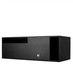
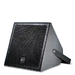
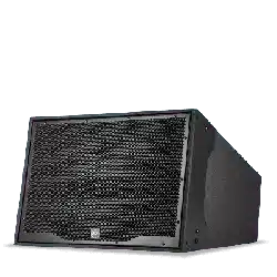
HL 2240, HL 2260 and HL 2290 are horn loaded two-way loudspeakers for array systems
for mid distance and long throw applications, both indoors and outdoors.
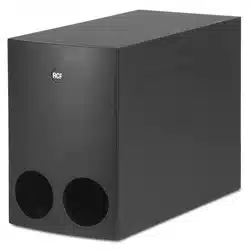
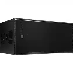
HS 2200 is the matched 18” subwoofer.
All trapezoidal enclosures are made of multi-ply Baltic birch plywood and nished in a very
resistant, textured, polyurea black paint.
Every enclosure shape has a 22.5° coupling angle.
Connections to ampliers are made through watertight ‘Amphenol’ 4-pole connectors.
Front grilles are made of custom perforated steel, epoxy coated, with open-cell bres and
water repellent woven fabric backing.
HL 2240, HL 2260, HL 2290
The three models only differ in their horizontal coverage angle:
40° (HL 2240), 60° (HL 2260), 90° (HL 2290).
Each speaker:
- is equipped with RCF precision transducers: two 12” woofers and a 1.5” titanium
compression driver (with 4” voice coil)
- is very compact, provides a high sound pressure level and an accurate sound reproduction
- has a 22.5° vertical dispersion and can be either used in point source congurations for
mid distances or clustered with narrower angles for long-throw applications.
HS 2200 SUBWOOFER
It is equipped with a single 18” woofer (RCF precision transducer) with a 4” voice coil.
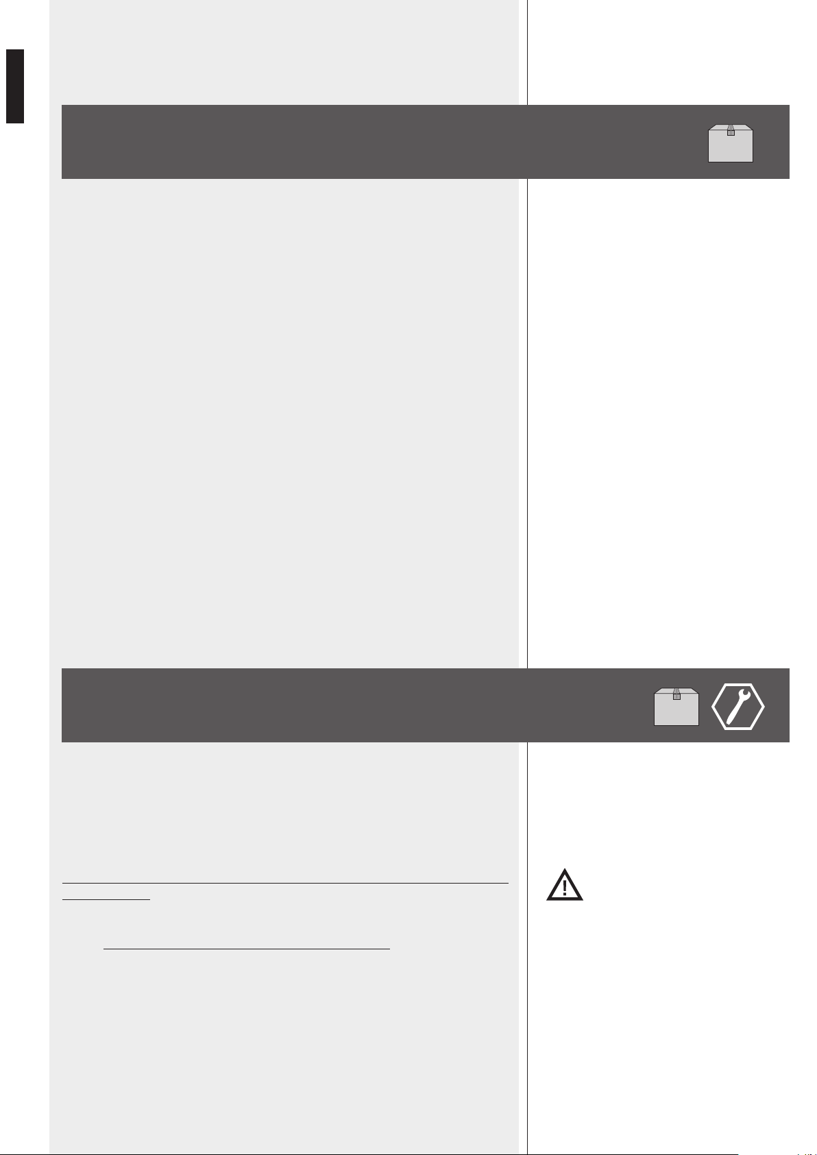
Loudspeakers need to be installed securely by qualied personnel, respecting all safety
standards. Make sure support structures (walls / ceilings / trusses) have the necessary
mechanical characteristics for the total loudspeaker weight, without the risk of a fall that
could damage things or cause injuries. Use suitable attachments elements only.
Warning: never make arrays With more than 6 speakers (each)!
HL series speakers (and HS 2200 subwoofers) can be installed as suspended line arrays,
each including from 2 to (max.) 6 speakers. A single speaker installation is not
foreseen.
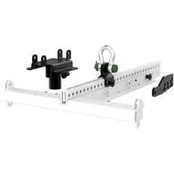
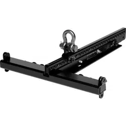
At least a ybar (that needs to be purchased, model RCF FLYBAR HL 2260) is necessary.
Line arrays can be hanged by using chains and M20 D-shackles (not included).
M10 screws for the front side and M12 screws with nuts for the rear side are included.

7
ENGLISH

8
ENGLISH
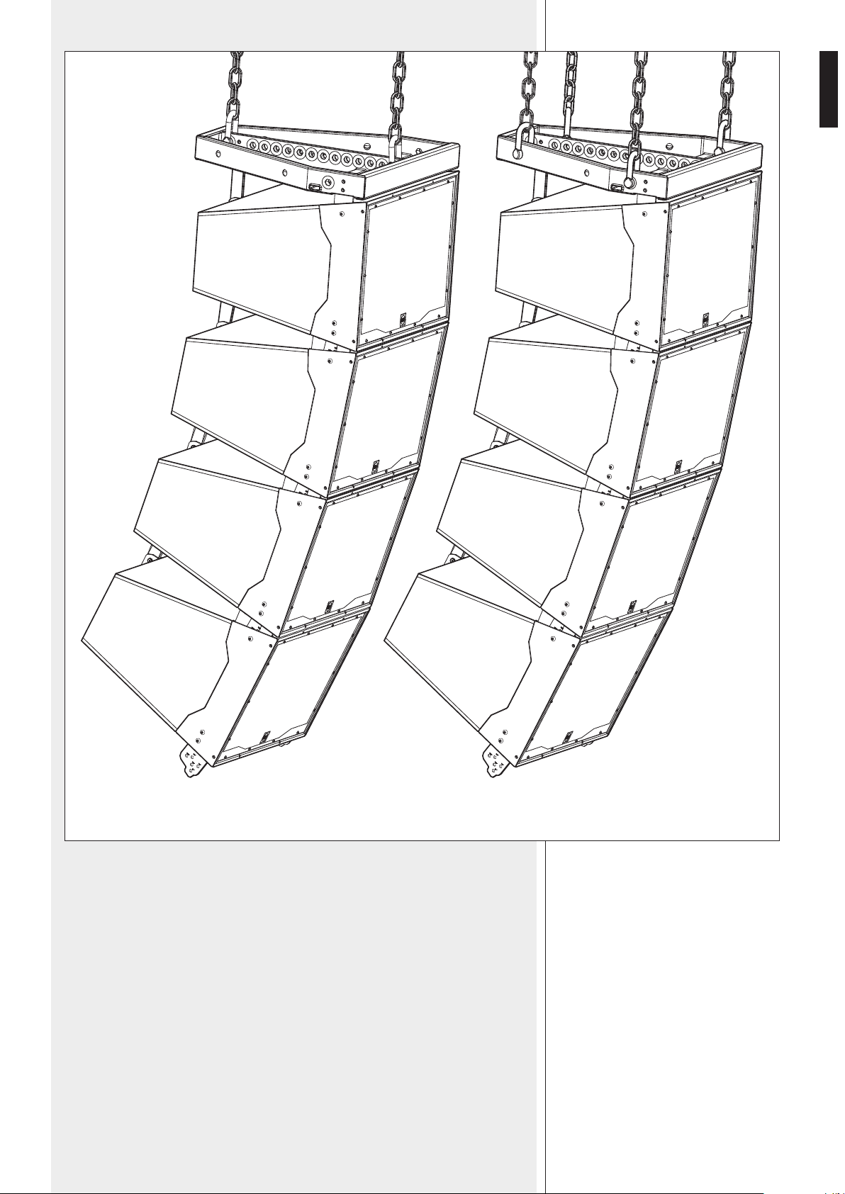
It is also possible to use two ybars to get a 6-speaker array as shown in the gure
below.
The angle between a ybar and its rst cabinet is 0°.
FLYBAR
33,75°
22,5°

9
ENGLISH
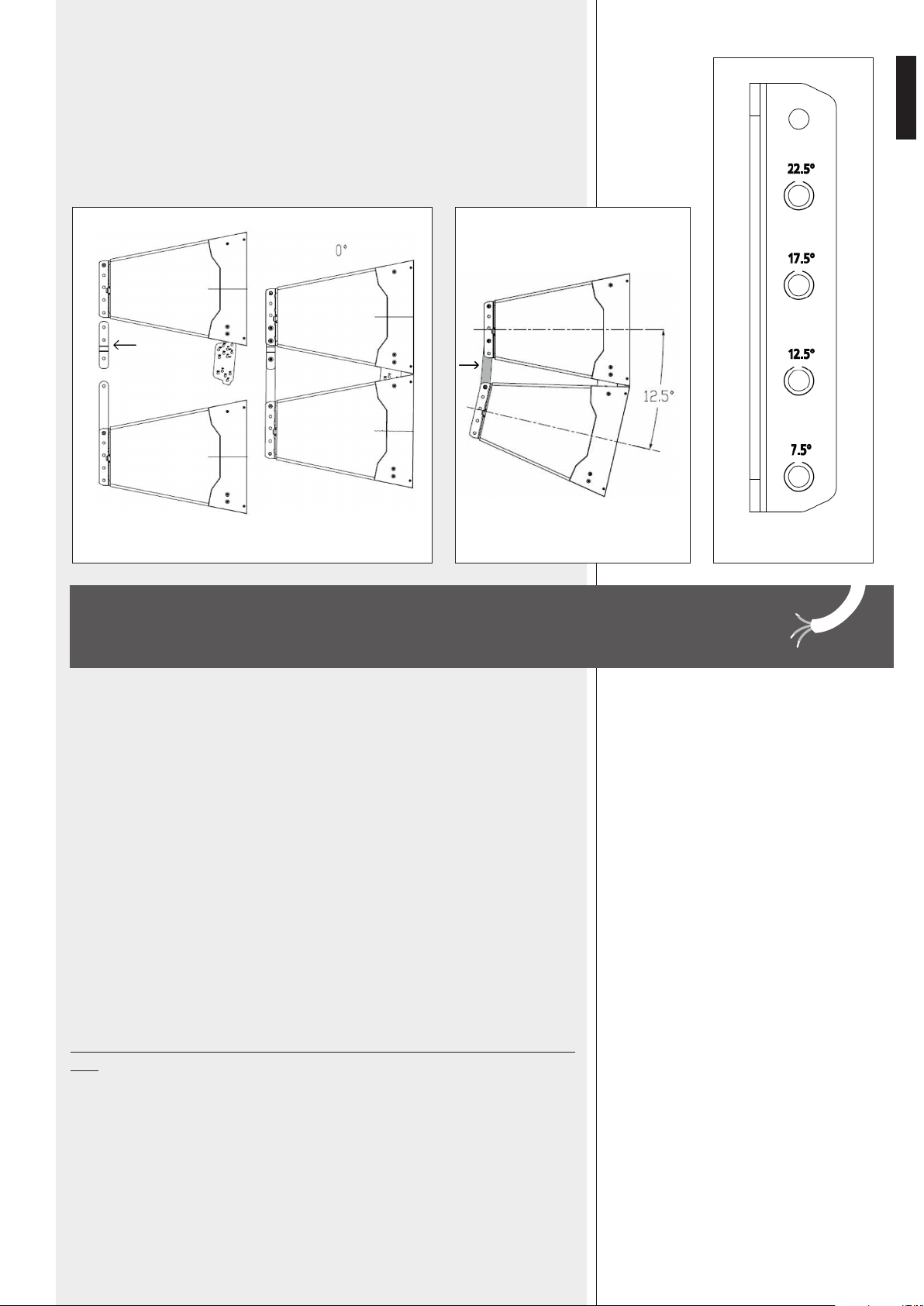
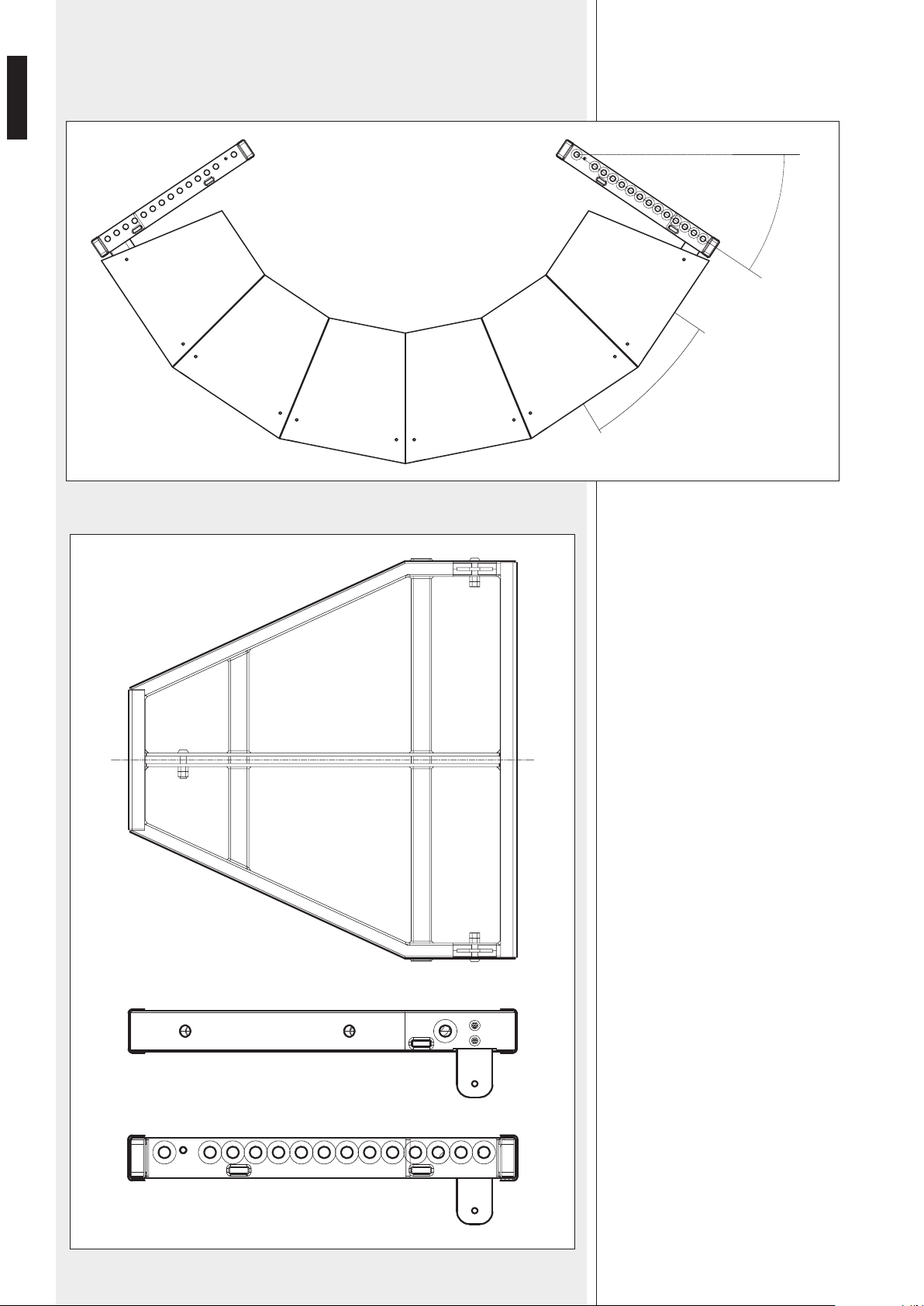
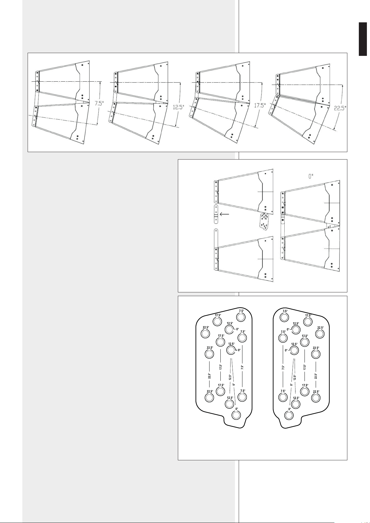
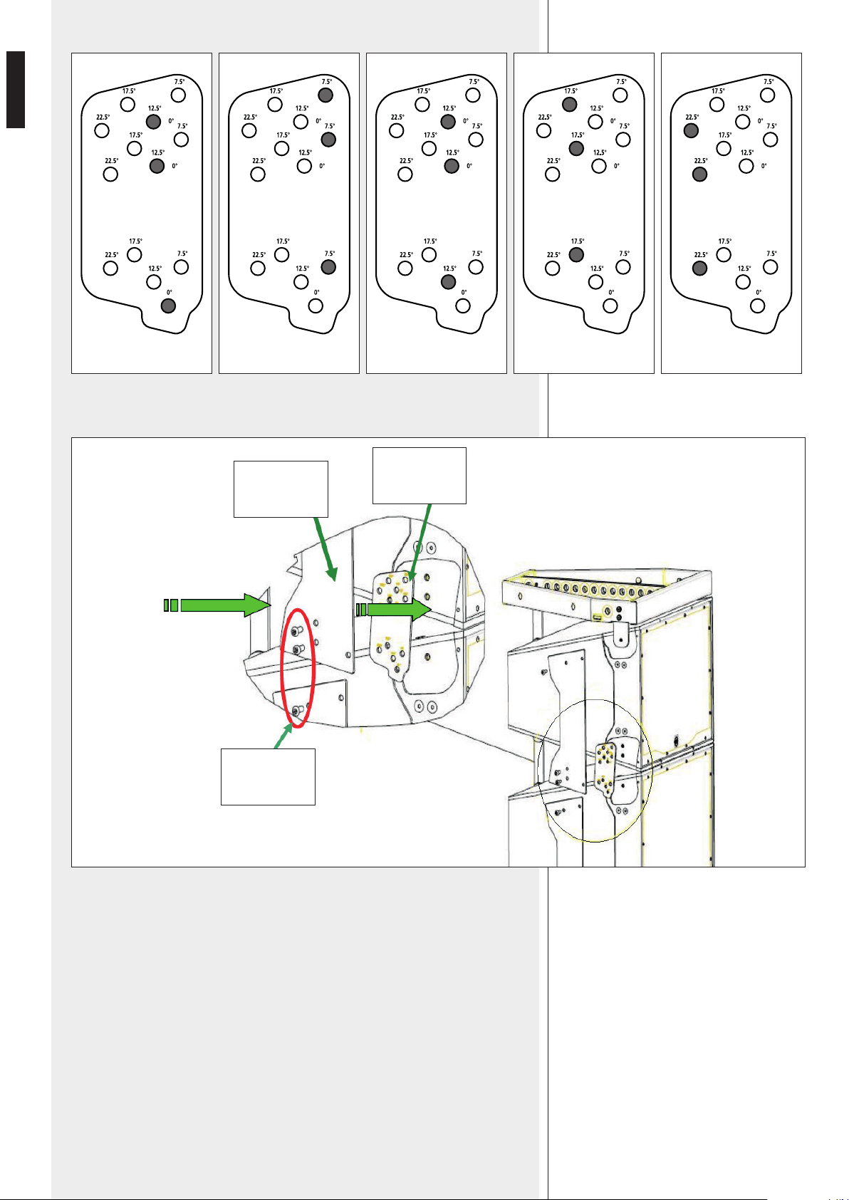
The angle between two adjacent cabinets can be set to 0°, 7.5°, 12.5°, 17.5°, 22.5°.
A dedicated acoustic project / study needs to be carried out to nd the proper angle.
If the angle between two cabinets is set to 0°, it will be
necessary to add the additional rear linking plate.
Both (left and right) front xing plates have several
holes that are labelled with the corresponding angle
setting.
A pair of upper holes shall be used for the upper
speaker, a lower hole for the lower speaker.
LATO SINISTRO
LEFT SIDE
LATO DESTRO
RIGHT SIDE

10
ENGLISH
0° 7.5° 12.5° 17.5° 22.5°
Fix the front side of two cabinets as shown in the next gure.
EXTERNAL
BRACKET
FIXING
PLATE
M10
SCREWS
11
ENGLISH
Then, x the rear bracket, by using the hole corresponding to the proper angle.
If the angle between two cabinets is set to 0°, it will be necessary to add the
additional rear linking plate.
WARNING: loudspeaker connections should be only made by qualied and experienced
personnel having the technical know-how or sufcient specic instructions (to ensure that
connections are made correctly) in order to prevent any electrical danger. To prevent any
risk of electric shock, do not connect loudspeakers when the amplier is switched on.
Before turning the system on, check all connections and make sure there are no accidental
short circuits.
The entire sound system shall be designed and installed in compliance with the current
local laws and regulations regarding electrical systems.
To ensure a correct sound reproduction, loudspeaker phase is to be respected (loudspeakers
are connected respecting the amplier polarity).
To prevent inductive effects from causing hum, noise and a bad system working, loudspeaker
lines should not be laid together with other electric cables (mains), microphone or line level
signal cables connected to amplier inputs.
The loudspeaker cable shall have wires (twisted, if possible, to reduce inductive effects due
to surrounding electro-magnetic elds) with a suitable section (min. 1.5 mm² – max. 2.5
mm²) and a sufcient electrical insulation.
NEVER connect HL series (and HS 2200) speakers directly to 70 / 100 V constant voltage
lines.
EXAMPLE: 0° EXAMPLE: 12.5°
REAR BRACKET
CONNECTION

12
ENGLISH
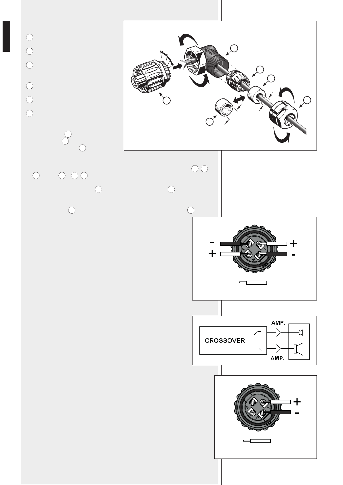
‘AMPHENOL ®’ TYPE CONNECTOR
A
: angled back shell
B
: clamping ring
C
1
: mounted gasket (for the clamping ring)
C
2
: alternative gasket
D
: nut
E
: female contact insert with locking ring
1. The
C
1
gasket is already inserted into the
clamping ring
B
: if necessary, replace it
by the alternative one
C
2
having a wider
hole.
2. Insert the cable (coming from the amplier)
through the connector parts (in order)
D
,
C
1
–
B
(or
C
2
–
B
),
A
.
3. Put the clamping ring
B
into the angled back shell
A
as shown above.
4. Tighten the nut
D
to x the clamping ring to the angled back shell
A
.
HL 2240, HL 2260, HL 2290
On the rear panel, there are 2 inputs linked in parallel (the second can be used
as an output for another loudspeaker) for ‘Amphenol’ plugs.
Plug pins:
1. WF +, woofer positive input (low frequencies)
2. WF –, woofer negative input (low frequencies)
3. TW +, tweeter positive input (high frequencies)
4. TW –, tweeter negative input (high frequencies)
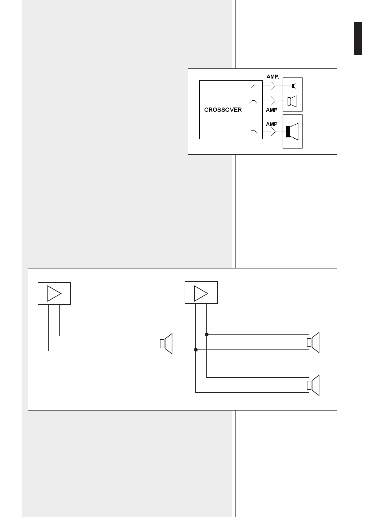
TWO-WAY MODE (NO HS 2200 SUBWOOFERS)
At least two ampliers (one for low frequencies, one for high frequencies) and
an external crossover are necessary.
Low frequency nominal impedance: 8 Ω
Low frequency recommended amplier power: 2700 W
High frequency nominal impedance: 8 Ω
High frequency recommended amplier power: 300 W
Suggested crossover frequency: 600 Hz
HS 2200
On the rear panel, there are 2 inputs linked in parallel (the second can be used as an
output for another subwoofer) for ‘Amphenol’ plugs.
Plug pins:
1. subwoofer positive input
2. subwoofer negative input.
Do not connect pins 3 and 4.
MAX. Ø : 2.5 mm
2
4
WFTW
HL 2240
HL 2260
HL 2290
(4)
(3)
(1)
(2)
MAX. Ø : 2.5 mm
2
4
HS 2200
(1)
(2)
A
B
C
1
D
E
6-9 mm
9-12.5 mm
C
2
13
ENGLISH
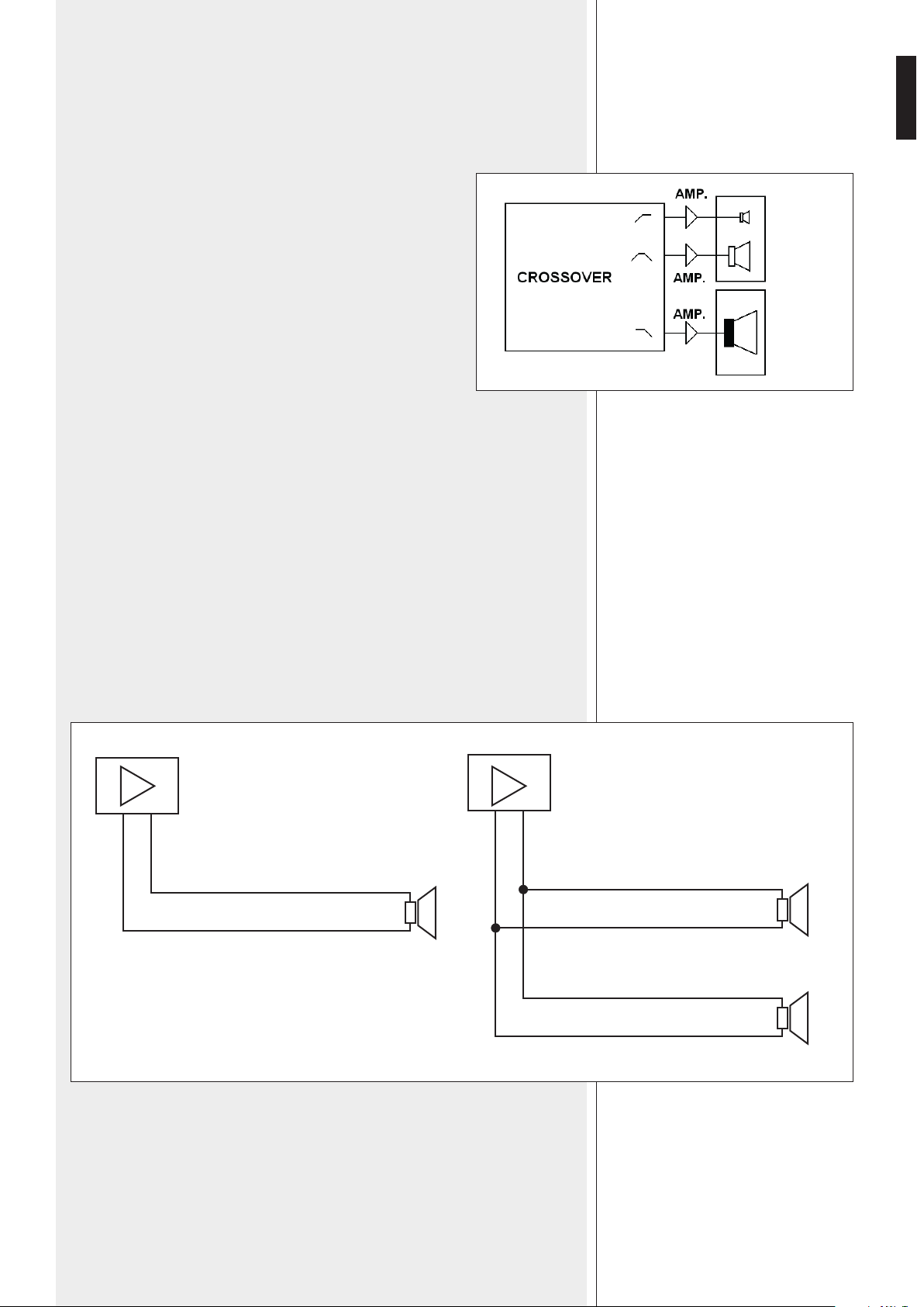
THREE-WAY MODE (WITH HS 2200 SUBWOOFERS)
At least three ampliers (one for each way) and an external crossover are necessary.
HL 2240, HL 2260, HL 2290
low-frequency nominal impedance: 8 Ω
low-frequency recommended amplier power: 2700 W
high-frequency nominal impedance: 8 Ω
high-frequency recommended amplier power: 300 W
HS 2200 SUBWOOFER
nominal impedance: 8 Ω
recommended amplier power: 1800 W
Suggested crossover frequencies:
- 80 ÷ 120 Hz (HS 2200 subwoofer cutoff)
- 600 Hz (HL 2240, HL 2260, HL 2290 woofer / tweeter).
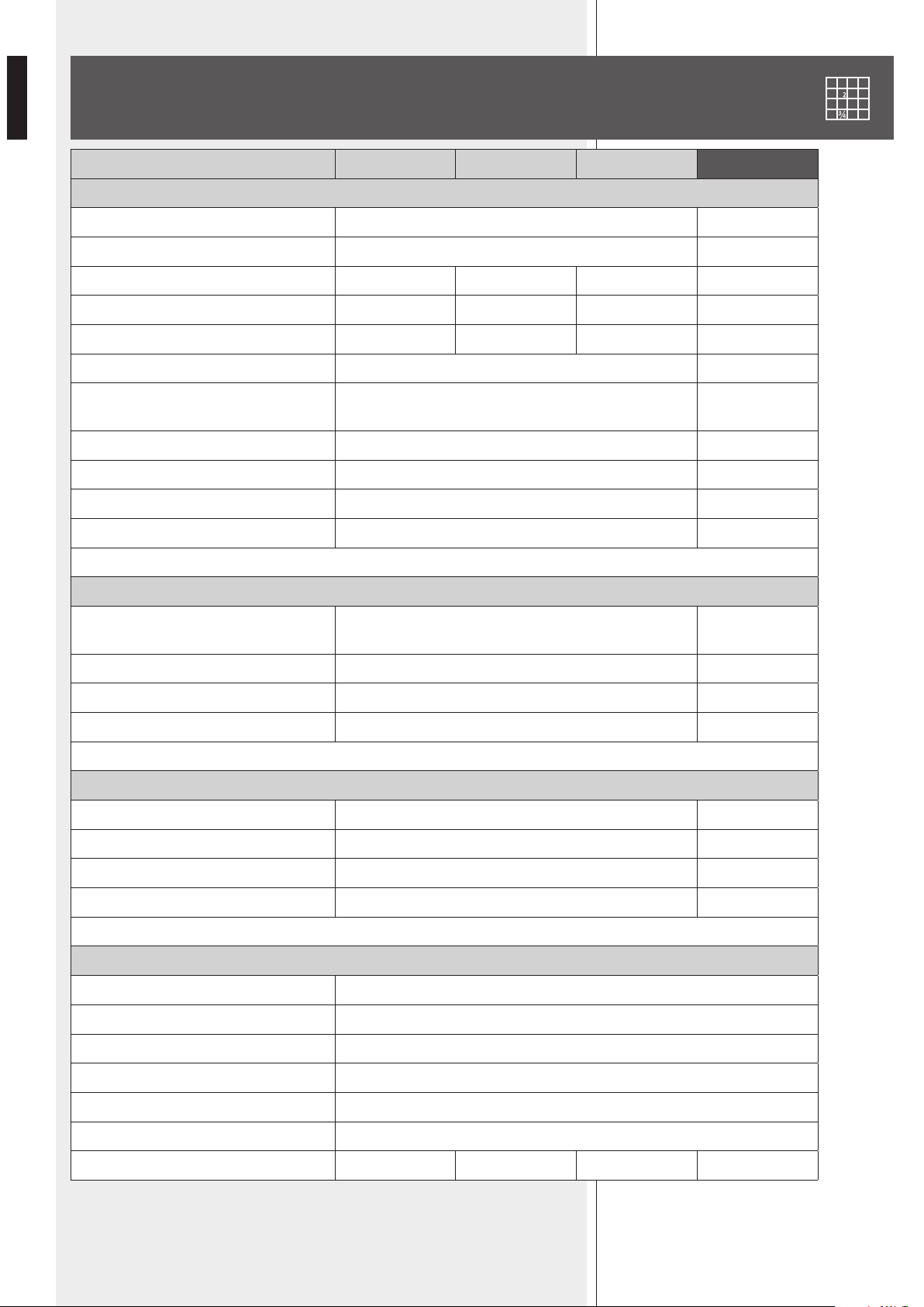
GENERIC NOTES ABOUT LOW IMPEDANCE CONNECTIONS
- The total loudspeaker impedance must not be lower than the amplier output
impedance. Note: a loudspeaker total impedance equal to the amplier output one
permits to get the maximum deliverable power (but a higher loudspeaker impedance
entails less power).
- The total loudspeaker power shall be adequate for the maximum deliverable power of
the amplier.
- The loudspeaker line shall as short as possible (for long distances, it may be necessary
to use cables with large cross-section wires).
- More loudspeakers linked in parallel: if the single loudspeaker impedance is 8 Ω, the
total impedance is given by 8 divided by the loudspeaker number. For example: the total
impedance of two loudspeakers linked in parallel is 4 Ω.
HL 2240
HL 2260
HL 2290
HL 2200
– +
+
8 Ω
TOTAL IMPEDANCE 8 Ω
– +
+
+
8 Ω
8 Ω
TOTAL IMPEDANCE 4 Ω
14
ENGLISH
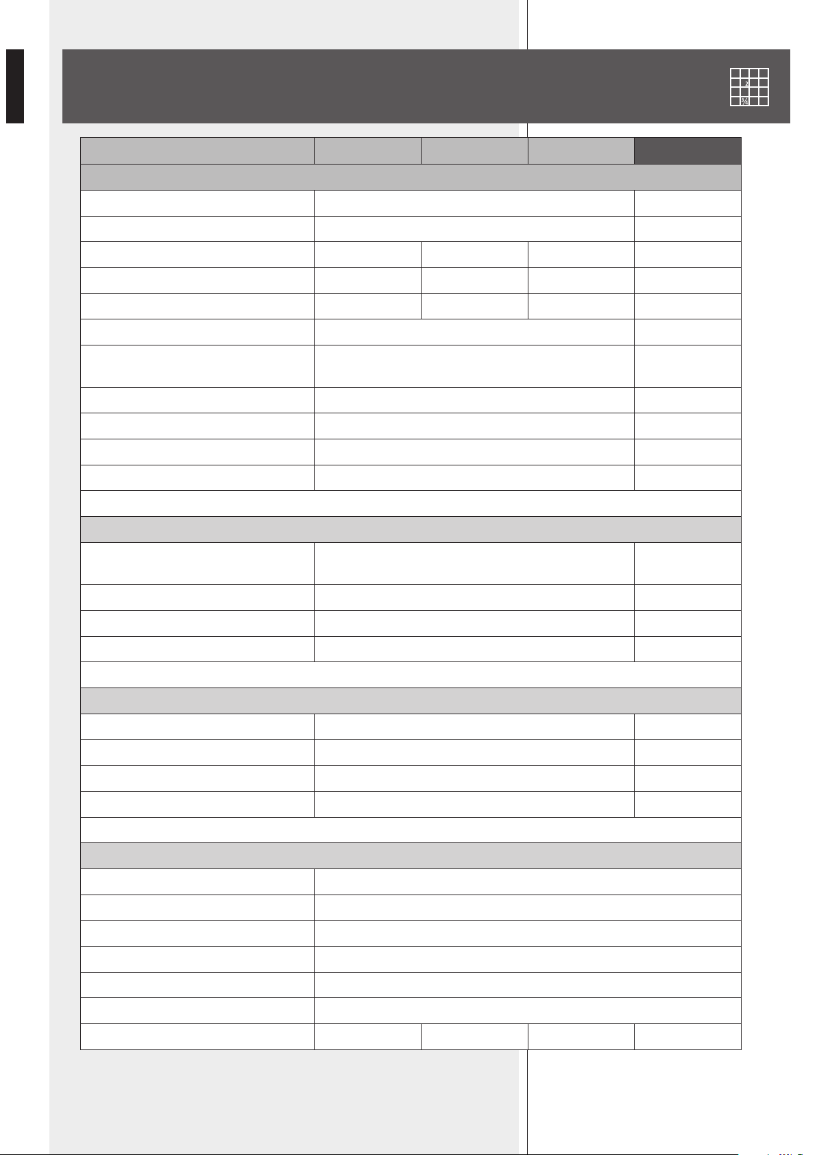
SPECIFICATIONS
HL 2240 HL 2260 HL 2290 HS 2200
SYSTEM
FREQUENCY RANGE (–10 dB) 60 Hz ÷ 20 kHz 30 ÷ 200 Hz
FREQUENCY RANGE (–3 dB) 80 Hz ÷ 20 kHz 35 ÷ 200 Hz
HOR. COVERANGE ANGLE (–6 dB) 40° 60° 90° -
VERT. COVERANGE ANGLE (–6 dB) 22.5° 22.5° 22.5° -
DIRECTIVITY FACTOR (Q) 16 14 13 -
SENSITIVITY (1 W, 1 m) WF: 104 dB, TW: 113 dB 100 dB
MAX. SOUND PRESSURE LEVEL
(peak power, 1 m)
141 dB 136 dB
INPUT NOMINAL POWER (RMS) WF: 1350 W, TW: 150 W 900 W
INPUT PEAK POWER WF: 5400 W, TW: 600 W 3600 W
RECOMMENDED AMPLIFIER WF: 2700 W, TW: 300 W 1800 W
SUGGESTED CROSSOVER FREQ. 600 Hz 80 ÷ 120 Hz
LOW FREQ. TRANSDUCERS
NUMBER AND TYPE 2 x 12” woofer (3.5” voice coil)
1 x 18” woofer
(4” voice coil)
NOMINAL IMPEDANCE 8 Ω 8 Ω
AES POWER RATING 1350 W 900 W
SENSITIVITY (1 W, 1 m) 104 dB 100 dB
HI FREQ. TRANSDUCERS
NUMBER AND TYPE 1 x 1.5” compression driver (4” voice coil) -
NOMINAL IMPEDANCE 8 Ω -
AES POWER RATING 150 W -
SENSITIVITY (1 W, 1 m) 113 dB -
PHYSICAL
ENCLOSURE Trapezoidal, 15 mm birch plywood construction
RIGGING INSERTS Side and rear array rigging points
COLOUR Polyurea black, weather and scratch resistant paint
GRILLE Custom perforated steel grille
INPUT CONNECTORS Amphenol eco/mat IP 67
DIMENSIONS (w, h, d) 771 mm (30.35”), 530 mm (20.87”), 635 mm (25.00”)
NET WEIGHT 62 kg (137 lbs) 60 kg (132 lbs) 62 kg (137 lbs) 60 kg (132 lbs)

15
ITALIANO
ITALIANO
AVVERTENZE PER LA SICUREZZA
DESCRIZIONE
INSTALLAZIONE
COLLEGAMENTO
SPECIFICHE TECNICHE
16
18
18
23
26
INDICE
16
ITALIANO
IMPORTANTE
Prima di collegare ed utilizzare questo prodotto, leggere attentamente le istruzioni
contenute in questo manuale, il quale è da conservare per riferimenti futuri.
Il presente manuale costituisce parte integrante del prodotto e deve accompagnare
quest’ultimo anche nei passaggi di proprietà, per permettere al nuovo proprietario di
conoscere le modalità d’installazione e d’utilizzo e le avvertenze per la sicurezza.
L’installazione e l’utilizzo errati del prodotto esimono la RCF S.p.A. da ogni responsabilità.
AVVERTENZE PER LA SICUREZZA E PRECAUZIONI D’USO
1. Tutte le avvertenze, in particolare quelle relative alla sicurezza, devono essere lette con
particolare attenzione, in quanto contengono importanti informazioni.
2. La linea diffusori (uscita dell’amplicatore) può avere una tensione sufcientemente alta
da costituire un rischio di folgorazione per le persone: non procedere mai all’installazione
o alla connessione del diffusore quando l’amplicatore è acceso.
3. Assicurarsi che tutte le connessioni siano corrette e che l’impedenza del diffusore sia
compatibile con le caratteristiche d’uscita dell’amplicatore.
4. Accertarsi che la linea diffusori non possa essere calpestata o schiacciata da oggetti, al
ne di salvaguardarne la perfetta integrità.
5. Impedire che oggetti o liquidi entrino all’interno del prodotto, perché potrebbero causare
un corto circuito.
6. Non eseguire sul prodotto interventi / modiche / riparazioni se non quelle espressamente
descritte sul manuale istruzioni.
Contattare centri di assistenza autorizzati o personale altamente qualicato quando:
- il diffusore non funziona (o funziona in modo anomalo);
- il cavo è danneggiato;
- oggetti o liquidi sono entrati nel diffusore;
- il diffusore non è più integro (a causa di urti / incendio).
7. Nel caso che dal diffusore provengano odori anomali o fumo, spegnere immediatamente
l’amplicatore relativo alla linea e poi scollegare il diffusore.
8. Non collegare a questo diffusore apparecchi ed accessori non previsti.
Quando è prevista l’installazione sospesa, utilizzare solamente gli appositi punti di
ancoraggio e non cercare di appendere il diffusore con elementi non idonei o previsti allo
scopo.
Vericare inoltre l’idoneità del supporto (parete, softto, struttura ecc.) e dei componenti
utilizzati per il ssaggio (tasselli, viti, staffe non fornite da RCF ecc.) che devono garantire
la sicurezza dell’impianto / installazione nel tempo, anche considerando, ad esempio,
vibrazioni meccaniche normalmente generate da un trasduttore.
9. La RCF S.P.A. raccomanda vivamente che l’installazione di questo prodotto sia eseguita
solamente da installatori professionali qualicati (oppure da ditte specializzate) in grado di
farla correttamente e certicarla in accordo con le normative vigenti. Tutto il sistema audio
dovrà essere in conformità con le norme e le leggi vigenti in materia di impianti elettrici.
10. I fattori meccanici ed elettrici sono da considerare quando si installa un sistema audio
professionale (oltre a quelli prettamente acustici, come la pressione sonora, gli angoli di
copertura, la risposta in frequenza, ecc.).
IMPORTANTE
AVVERTENZE PER
LA SICUREZZA

17
ITALIANO
11. Perdita dell’udito
L’esposizione ad elevati livelli sonori può provocare la perdita permanente dell’udito. Il
livello di pressione acustica pericolosa per l’udito varia sensibilmente da persona a persona
e dipende dalla durata dell’esposizione. Per evitare un’esposizione potenzialmente
pericolosa ad elevati livelli di pressione acustica, è necessario che chiunque sia sottoposto
a tali livelli utilizzi delle adeguate protezioni; quando si fa funzionare un trasduttore in
grado di produrre elevati livelli sonori è necessario indossare dei tappi per orecchie o delle
cufe protettive.
Consultare i dati tecnici contenuti nel manuale istruzioni per conoscere la massima
pressione sonora che il diffusore acustico è in grado di produrre.
12. I diffusori acustici devono essere collegati in fase (corrispondenza delle
polarità + / – tra amplificatori e diffusori) in modo da garantire una corretta
riproduzione audio, soprattutto quando i diffusori sono collocati in posizione fra
loro adiacente o nello stesso ambiente.
13. Per evitare che fenomeni induttivi diano luogo a ronzii, disturbi e compromettano il
buon funzionamento dell’impianto, le linee diffusori non devono essere canalizzate insieme
ai conduttori dell’energia elettrica, ai cavi microfonici, alle linee di segnale a basso livello
che fanno capo ad amplicatori.
14. Il cavo per il collegamento del diffusore dovrà avere conduttori di sezione adeguata
(possibilmente intrecciati, per minimizzare gli effetti induttivi dovuti all’accoppiamento con
campi elettromagnetici circostanti) ed un isolamento idoneo.
15. Non collegare ingressi a bassa impedenza (8 Ω) dei diffusori acustici ad una linea a
tensione costante (100 V).
16. Collocare il diffusore lontano da fonti di calore.
17. Non sovraccaricare il diffusore con una potenza eccessiva.
18. Non usare solventi, alcool, benzina o altre sostanze volatili per la pulitura delle parti
esterne; usare un panno asciutto.
18
ITALIANO
RCF S.P.A. VI RINGRAZIA PER L’ACQUISTO DI QUESTO PRODOTTO, REALIZZATO
IN MODO DA GARANTIRNE L’AFFIDABILITÀ E PRESTAZIONI ELEVATE.
DESCRIZIONE
INSTALLAZIONE
HL 2240, HL 2260 e HL 2290 sono diffusori acustici a due vie da combinare in “line array”
per la copertura di medie e lunghe distanze, sia al chiuso sia all’aperto.
HS 2200 è il subwoofer (diffusore da 18” per le frequenze più basse) da abbinare alla
serie HL.
I mobili sono trapezoidali, realizzati con compensato multistrato di betulla del Baltico e
niti con vernice nera resistente ai graf.
La forma del mobile ha un angolo di 22,5°.
Il collegamento all’amplicatore si effettua tramite connettori a 4 poli di tipo “Amphenol”.
Le griglie anteriori sono in acciaio perforato verniciato a polveri epossidiche, con bre a
celle aperte e protezione in tessuto idrorepellente.
HL 2240, HL 2260, HL 2290
I tre modelli differiscono tra loro solo per l’angolo di copertura orizzontale:
40° (HL 2240), 60° (HL 2260), 90° (HL 2290).
Ciascun diffusore acustico:
- è dotato di trasduttori “RCF precision”, due woofer da 12” ed un driver a compressione
in titanio da 1,5” (con bobina da 4”);
- è molto compatto, fornisce un’elevata pressione sonora ed una riproduzione accurata;
- ha una dispersione verticale di 22,5° e può essere utilizzato sia in congurazioni “point
source” per medie distanze o messo a “cluster” con angoli più stretti per lunghe gittate.
HS 2200 (SUBWOOFER)
È dotato di un singolo woofer da 18” (serie “RCF precision”) con bobina da 4”.
L’installazione dei diffusori deve essere effettuata da personale qualicato rispettando gli
standard di sicurezza. Eseguire un’installazione sicura di ogni diffusore, controllando che la
struttura di supporto (es. parete, softto, tralicci, ecc.) abbia le necessarie caratteristiche
meccaniche, tali da consentirle di sopportarne il peso senza il pericolo di cadute che
potrebbero compromettere l’incolumità di persone e/o danneggiare cose.
Utilizzare solo elementi di ssaggio adatti.
attenzione: non assemblare mai “array” (schiere di diffusori in linea) con più di 6 diffusori
acustici ciascuno!
I diffusori della serie HL (ed i subwoofer HS 2200) possono essere installati come “array”
appesi, ciascuno avente dai 2 a (max.) 6 diffusori acustici.
L’installazione di singoli diffusori acustici non è prevista.
Almeno un “ybar” (che deve essere acquistato, modello RCF FLYBAR HL 2260) è
necessario.
Gli “array” possono essere appesi tramite l’uso di catene e grilli M20 (non inclusi).
Sono incluse le viti di ssaggio: M10 per il lato anteriore e M12 per il retro.
19
ITALIANO
20
ITALIANO
È possibile, inoltre, utilizzare due “ybar” per ottenere un “array” con 6 diffusori come
mostrato nella gura sotto.
L’angolo tra un “ybar” ed il primo diffusore acustico è 0°.
FLYBAR
33,75°
22,5°
21
ITALIANO
L’angolo tra due diffusori adiacenti può essere 0°, 7,5°, 12,5°, 17,5° oppure 22,5°.
La scelta dell’angolo più opportuno necessita di uno studio acustico dedicato.
Se l’angolo tra due diffusori è 0°, è necessario inserire la
piastra di ssaggio posteriore addizionale.
Entrambe le piastre di ssaggio anteriori (sinistra e
destra) hanno dei fori con le indicazioni degli angoli
di ssaggio corrispondenti.
Le coppie di fori in alto sono usate per il diffusore
superiore, i fori in basso per quello inferiore.
LATO SINISTRO
LEFT SIDE
LATO DESTRO
RIGHT SIDE
22
ITALIANO
0° 7,5° 12,5° 17,5° 22,5°
Fissare il lato frontale dei diffusori acustici come mostrato nella gura seguente.
STAFFA
ESTERNA
PIASTRA DI
FISSAGGIO
VITI M10

23
ITALIANO
Successivamente, ssare la staffa posteriore usando il foro corrispondente
all’angolo scelto.
Se l’angolo tra due diffusori è 0°, è necessario inserire la piastra di ssaggio
posteriore addizionale.
ATTENZIONE: per il collegamento del diffusore si raccomanda di rivolgersi a personale
qualicato ed addestrato, ossia avente conoscenze tecniche o esperienza o istruzioni
speciche sufcienti per permettergli di realizzare correttamente le connessioni e prevenire
i pericoli dell’elettricità.
Per evitare il rischio di shock elettrici, non collegare il diffusore con l’amplicatore acceso.
Prima di far funzionare il diffusore, è buona norma ricontrollare tutte le connessioni,
vericando attentamente che non vi siano dei cortocircuiti accidentali.
Tutto l’impianto di sonorizzazione dovrà essere realizzato in conformità con le norme e le
leggi vigenti in materia di impianti elettrici.
I diffusori acustici devono essere collegati in fase (corrispondenza delle polarità +/- tra
amplicatori e diffusori) in modo da garantire una corretta riproduzione audio.
Per evitare che fenomeni induttivi diano luogo a ronzii, disturbi e compromettano il buon
funzionamento dell’impianto, le linee diffusori non devono essere canalizzate insieme ai
conduttori dell’energia elettrica, ai cavi microfonici, alle linee di segnale a basso livello che
fanno capo ad amplicatori.
Il cavo per il collegamento del diffusore dovrà avere un isolamento idoneo e conduttori di
sezione adeguata (min. 1,5 mm² – max. 2,5 mm²), possibilmente intrecciati, per minimizzare
gli effetti induttivi dovuti all’accoppiamento con campi elettro-magnetici circostanti.
NON collegare mai i diffusori serie HL (e HS 2200) direttamente a linee con tensione
costante 100 / 70 V.
ESEMPIO: 0° ESEMPIO: 12,5°
STAFFA POSTERIORE
COLLEGAMENTO
24
ITALIANO
CONNETTORE DI TIPO AMPHENOL ®
A
: guscio posteriore angolato
B
: anello di bloccaggio
C
1
: guarnizione montata (per l’anello di
bloccaggio)
C
2
: guarnizione alternativa
D
: dado
E
: connettore con anello di bloccaggio
1. La guarnizione
C
1
è già inserita nell’anello
di bloccaggio
B
: se necessario, sostituirla
con quella alternativa
C
2
avente un foro
più grande.
2. Inserire il cavo (proveniente dall’amplicatore) attraverso le parti (in ordine)
D
,
C
1
–
B
(oppure
C
2
–
B
,
A
.
3. Inserire l’anello di bloccaggio
B
nel guscio posteriore angolato
A
come mostrato
sopra.
4. Stringere il dado
D
per ssare l’anello di bloccaggio al guscio posteriore
A
.
HL 2240, HL 2260, HL 2290
Sul retro vi sono 2 ingressi posti in parallelo (il secondo può essere usato come
uscita per un altro diffusore acustico) per connettori “Amphenol”.
Piedinatura del connettore:
1. WF +, ingresso positivo del woofer (freq. basse);
2. WF –, ingresso negativo del woofer (freq. basse);
3. TW +, ingresso positivo del tweeter (freq. alte);
4. TW –, ingresso negativo del tweeter (freq. alte).
CONFIGURAZIONE A DUE VIE
(senza subwoofer HS 2200)
Sono necessari almeno due amplicatori (uno per le frequenze basse, uno per
le alte) ed un crossover esterno.
Impedenza nominale (frequenze basse): 8 Ω
Potenza amplicatore raccomandato (freq. basse): 2700 W
Impedenza nominale (frequenze alte): 8 Ω
Potenza amplicatore raccomandato (freq. alte): 300 W
Frequenza suggerita del crossover: 600 Hz
HS 2200
Sul retro vi sono 2 ingressi posti in parallelo (il secondo può essere usato come uscita per
un altro subwoofer) per connettori “Amphenol”.
Piedinatura del connettore:
1. ingresso positivo;
2. ingresso negativo.
Non collegare i contatti 3 e 4.
MAX. Ø : 2.5 mm
2
4
WFTW
HL 2240
HL 2260
HL 2290
(4)
(3)
(1)
(2)
MAX. Ø : 2.5 mm
2
4
HS 2200
(1)
(2)
A
B
C
1
D
E
6-9 mm
9-12,5 mm
C
2
25
ITALIANO
CONFIGURAZIONE A TRE VIE (CON SUBWOOFER HS 2200)
Sono necessari almeno tre amplicatori (uno per ogni via) ed un crossover esterno.
HL 2240, HL 2260, HL 2290
Impedenza nominale (frequenze basse): 8 Ω
Potenza amplicatore raccomandato (freq. basse): 2700 W
Impedenza nominale (frequenze alte): 8 Ω
Potenza amplicatore raccomandato (freq. alte): 300 W
SUBWOOFER HS 2200
Impedenza nominale: 8 Ω
Potenza amplicatore raccomandato: 1800 W
Frequenze suggerite del crossover:
- 80 ÷ 120 Hz (frequenza di taglio per il subwoofer HS 2200)
- 600 Hz (woofer / tweeter nei modelli HL 2240, HL 2260, HL 2290).
NOTE GENERICHE SUI SISTEMI CON CONNESSIONE A BASSA
IMPEDENZA
- L’impedenza totale dei diffusori non deve essere inferiore a quella d'uscita
dell'amplicatore; nota: l'impedenza complessiva dei diffusori uguale a quella d'uscita
dell'amplicatore permette l'erogazione della massima potenza (mentre un’impedenza
superiore comporta una riduzione della potenza erogata).
- La somma delle potenze dei diffusori deve essere adeguata alla potenza massima
erogabile dall’amplicatore.
- La lunghezza delle linee diffusori deve essere ridotta al minimo (una lunga distanza può
comportare l’uso di cavi con sezioni elevate).
- Più diffusori acustici collegati in parallelo: se l'impedenza di un singolo diffusore è 8 Ω,
il valore dell'impedenza totale è dato da 8 diviso per numero di diffusori.
- Ad esempio: l'impedenza totale di due diffusori collegati in parallelo è 4 Ω.
HL 2240
HL 2260
HL 2290
HL 2200
– +
+
8 Ω
IMPEDENZA COMPLESSIVA 8 Ω
– +
+
+
8 Ω
8 Ω
IMPEDENZA COMPLESSIVA 4 Ω
26
ITALIANO
SPECIFICHE TECNICHE
HL 2240 HL 2260 HL 2290 HS 2200
SISTEMA
CAMPO DI FREQUENZE (–10 dB) 60 Hz ÷ 20 kHz 30 ÷ 200 Hz
CAMPO DI FREQUENZE (–3 dB) 80 Hz ÷ 20 kHz 35 ÷ 200 Hz
ANGOLO COPERTURA ORIZ.(–6 dB) 40° 60° 90° -
ANGOLO COPERTURA VERT.(–6 dB) 22,5° 22,5° 22,5° -
FATTORE DI DIRETTIVITÀ (Q) 16 14 13 -
SENSITIVITÀ (1 W, 1 m) WF: 104 dB, TW: 113 dB 100 dB
MAX. PRESSIONE SONORA
(potenza di picco, 1 m)
141 dB 136 dB
POTENZA NOMINALE (RMS) WF: 1350 W, TW: 150 W 900 W
POTENZA DI PICCO WF: 5400 W, TW: 600 W 3600 W
AMPLIFICATORE RACCOMANDATO WF: 2700 W, TW: 300 W 1800 W
FREQ. SUGGERITA CROSSOVER 600 Hz 80 ÷ 120 Hz
TRASDUTTORI FREQ. BASSE
NUMERO E TIPO 2 x woofer 12” (bobina 3,5”)
1 x woofer 18”
(bobina 4”)
IMPEDENZA NOMINALE 8 Ω 8 Ω
POTENZA AES 1350 W 900 W
SENSITIVITÀ (1 W, 1 m) 104 dB 100 dB
TRASDUTTORI FREQ. ALTE
NUMERO E TIPO 1 x driver a compressione da 1,5” (bobina 4”) -
IMPEDENZA NOMINALE 8 Ω -
POTENZA AES 150 W -
SENSITIVITÀ (1 W, 1 m) 113 dB -
DATI MECCANICI
MOBILE Trapezoidale, multistrato di betulla 15 mm
INSERTI Laterali e posteriori
COLORE Nero, resistente ai graf ed agli agenti atmosferici
GRIGLIA DI PROTEZIONE Acciaio perforato
CONNETTORI D’INGRESSO Amphenol eco/mat IP 67
DIMENSIONI (l, h, p) 771 mm, 530 mm, 635 mm
PESO NETTO 62 kg 60 kg 62 kg 60 kg


10307409 revA
www.rcfaudio.com
HEADQUARTERS:
RCF S.p.A. Italy
tel. +39 0522 274 411
e-mail: info@rcf.it
RCF UK
tel. 0844 745 1234
Int. +44 870 626 3142
e-mail: [email protected].uk
RCF France
tel. +33 1 49 01 02 31
e-mail: france@rcf.it
RCF Germany
tel. +49 2203 925370
e-mail: germany@rcf.it
RCF Spain
tel. +34 91 817 42 66
e-mail: [email protected]
RCF Belgium
tel. +32 (0) 3 - 3268104
e-mail: belgium@rcf.it
RCF USA Inc.
tel. +1 (603) 926-4604
e-mail: [email protected]
Except possible errors and omissions.
RCF S.p.A. reserves the right to make modications without prior notice.
Salvo eventuali errori ed omissioni.
RCF S.p.A. si riserva il diritto di apportare modiche senza preavviso.
2013 / 12