Loading ...
2
PREPARACION
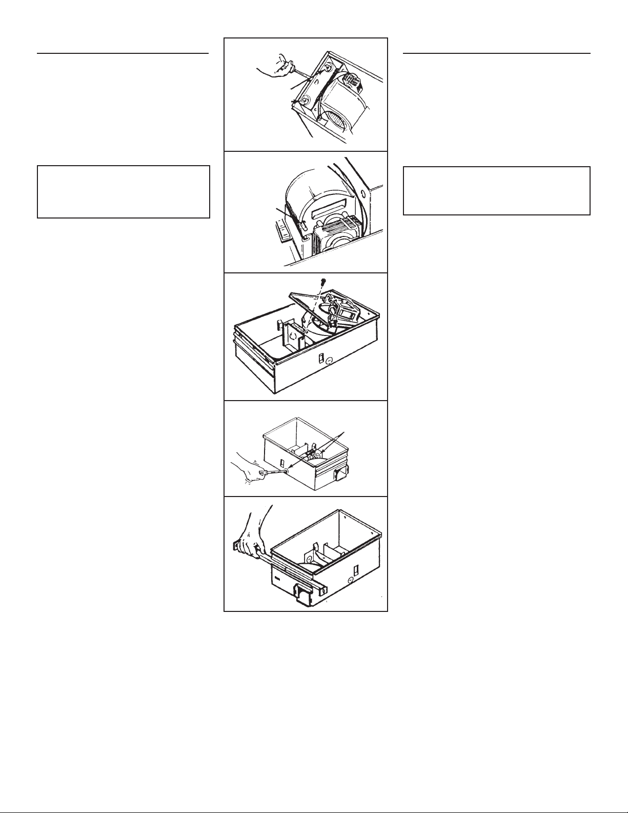
1. Desconecte el conjunto del calentador del enchufe ROJO.
2. Afloje los dos tornillos de retén en el interior de la entrada
de descarga del calentador.
Coloque la punta del destornillador entre la pared exterior
de la entrada de descarga y la carcasa del ventilador.
Haga palanca suavemente hacia afuera hasta que la
descarga del escape salga de la pestaña de apoyo en
la carcasa exterior. (FIG. 1)
3. Desenganche los pasadores de la bisagra y saque el
conjunto del calentador hacia afuera de la carcasa. (FIG. 2)
PRECAUCIÓN: Retire el anillo de embalaje de la entrada
del soplador del calentador antes de hacer funcionar el
calentador.
PASOS 4 Y 5 - SOLAMENTE PARA EL MODELO 658
4. Desconecte el ventilador del enchufe NEGRO. Saque
la bolsa de plástico y déjela a un lado.
5. Quite el tornillo de montaje y cuidadosamente saque
el ventilador hacia afuera de la carcasa. (FIG. 3)
6. Refiérase al diagrama de conexiones de la unidad
en la página siguiente. Saque los discos removibles
apropiados introduciendo la punta del desmontador en las
ranuras y moviendo éste de un lado a otro hasta romper
las pestañas. (FIG. 4)
7. Inserte lo soportes de montaje ajustables en los canales
para los soportes en la carcasa. (FIG. 5)
PREPARATION
1. Unplug the heater assembly from the RED recep-
tacle.
2. Loosen the two retaining screws on the inside of the
heater discharge opening.
Place a screwdriver tip between the outer wall of
the discharge opening and the fan housing. Gently
pry outward until the exhaust discharge slips off the
support lip on the outer housing. (FIG. 1)
3. Unhook hinge pins and lift heater assembly out of
housing. (FIG. 2)
CAUTION: Remove the shipping ring from the heater
blower inlet before operating the heater.
STEPS 4 & 5 - MODEL 658 ONLY
4. Unplug the fan assembly from the BLACK recep-
tacle. Remove the plastic bag and set it aside.
5. Remove the mounting screw and carefully lift the
fan assembly out of the housing. (FIG. 3)
6. Refer to the wiring diagram of your unit on the next
page. Remove appropriate knockout(s) by inserting
a screwdriver blade into slots and bending it back
and forth to break tabs. (FIG. 4)
7. Insert the adjustable mounting brackets into the
bracket channels on the housing. (FIG. 5)
FIG. 1
RETAINING
SCREWS
TORNILLOS DE
RETEN
FIG. 2
HINGE PINS
PASADORES
DE LA BIS-
AGRA
FIG. 3
FIG. 4
FIG. 5
KNOCKOUTS
DISCOS
REMOVIBLES
Loading ...
Loading ...
Loading ...