1
INSTALLATION, MAINTENANCE AND USE
INSTRUCTIONS FOR
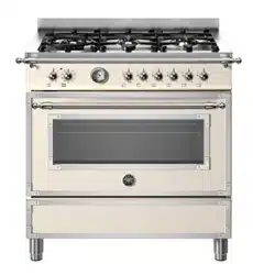
FREE-STANDING COOKERS
HER
PRO
3100344

2
READ THE INSTRUCTION BOOKLET BEFORE INSTALLING AND USING THE
APPLIANCE.
It is important that you retain these instructions, proof of purchase as well as other important documents
about this product for future reference.
The manufacturer will not be responsible for any damage to property or to persons caused by incorrect
installation or improper use of the appliance.
Due to continual product development, Bertazzoni Group reserves the right to alter specifications and
appearances without notice.
THIS APPLIANCE HAS BEEN DESIGNED FOR DOMESTIC USE ONLY TO BE
INSTALLED BY AN AUTHORISED PERSON
CONTENTS:
WARNINGS ................................................................................................................................. p
g
.3
LOCAL AUTHORITY REQUIREMENTS........................................................................................ p
g
.4
IMPORTANT INFORMATION FOR INSTALLING AND SERVICING THE APPLIANCE............... p
g
.6
APPLIANCE GAS CONNECTION ................................................................................................. p
g
.10
SUPPORT LEGS AND BACKGUARD INSTALLATION ............................................................... p
g
.11
ANTI-TIL DEVICE........................................................................................................................... P
g
.12
CONVERTION TO A DIFFERENT TYPE OF GAS........................................................................ p
g
.15
APPLIANCE ELECTRIC CONNECTION........................................................................................ p
g
.16
INSTALLATION CHECKLIST......................................................................................................... p
g
.17
APPLIANCE USE AND MAINTENANCE ....................................................................................... p
g
.18
GAS HOB……………………………………………………………………………………………………
pg.19
THE GRIDDLE ............................................................................................................................... p
g
.20
INDUCTION …………………………………………………………………………………………........ p
g
.22
SEPARATE GRILL COMPARTMENT
(
triple oven cavit
y
models onl
y)
…………………………….. p
g
.25
OVEN… ………………………………………………………………………………………………….... p
g
.26
USING THE AUTOMATIC PROGRAMMER…………………………………………………………… p
g
.32
OVEN TEMPERATURE GUIDE…………………………………………………………………………. p
g
.36
USING THE THERMOMETER…………………………………………………………………………... p
g
.38
CLEANING YOUR COOKER ……………………………………………………………………………. p
g
.39
ACCESSORIE………………………………………………………………………………………………
pg.43
TROUBLESHOOTING..................................................................................................................... p
g
.44
USEFUL TIPS.................................................................................................................................. p
g
.45
THIS APPLIANCE HAS BEEN DESIGNED FOR NON-PROFESSIONAL DOMESTIC USE.

3
WARNINGS
1. This appliance is not intended for use by persons (including children) with reduced physical, sensory
or mental capabilities, or lack of experience or knowledge, unless they have been given supervision
or instruction concerning the use of the appliance by a person responsible for their safety. Children
should be supervised to ensure that they do not play with the appliance.
2. DO NOT USE OR STORE FLAMMABLE MATERIALS IN THE APPLIANCE STORAGE DRAWER
OR NEAR THIS APPLIANCE. DO NOT SPRAY AEROSOLS IN THE VACINITY OF THIS
APPLIANCE WHILE IT IS IN OPERATION.
3. DO NOT MODIFY THIS APPLIANCE. This appliance is not suitable for use with aftermarket lids or
covers.
4. DO NOT PLACE ARTICLES ON OR AGAINST THIS APPLIANCE.
5. DO NOT USE THIS APPLIANCE AS A SPACE HEATER
6. WHERE THIS APPLIANCE IS INSTALLED IN MARINE CRAFT OR IN CARAVANS, IT SHALL NOT
BE USED AS A SPACE HEATER.
7. After removing the packaging, make sure to check if there is any damage to the appliance. If there is
any damage, never attempt to use the appliance and immediately contact your a uthorised Service
Centre. As packaging materials can be dangerous to children, they need to be collected immediately
and put out of reach.
8. In certain circumstances electrical appliances may be a safety hazard. The unit MUST be connected
to the electrical supply before operation to enable the electronic ignition to work. The electrical
connection must be accessible after installation. The appliance must be electrically isolated before
any maintenance can be performed.
9. Do not place heavy objects on this appliance (cooktop or door), use for storage or as a cutting surface,
as sharp edges can damage the surface. This appliance is designed for cooking only. If any damage
such as chips or cracks are seen in the glass, turn off all control knobs and do not use until the
appliance has been inspected by an authorised service person or replaced.
10. This appliance is designed for domestic household use only and for the cooking of domestic food
products. Use as a commercial appliance will void the warranty. It must not be used outdoors and
must be fully installed. Do not use the appliance until fully installed. If this appliance is installed on a
base, measures must be taken to prevent the appliance from slipping from the base.
11. Damage can occur to bench tops if pots and pans are able to overlap the bench top. This can result
in heat being transferred to the bench top. Ensure that correct sized pots & pans are used. Refer to
guide in instructions.
12. Do not allow pot handles or utensils to be placed near gas burners in operation, as they can cause
the handles to become hot to touch. Always turn handles away when small children are nearby. It is
recommended that children are kept away from the cooktop at all times.
13. Do not leave the cooktop while cooking with solid or liquid oils. There may be flaming up in conditions
of extreme heating. Never pour water onto the flames occurring from oil. Immediately turn the
cooktop off and cover the pan with a lid or fire blanket in order to smother the flame.
14. If the electrical supply cord is damaged, either when being installed or after installation, it must be
replaced by the manufacturer, its service agent or similarly qualified persons in order to prevent a
hazard.
15. The appliance is not intended to be operated by means of an external timer or separate remote control
system.
16. Electrical connection must be made as per local wiring rules and regulations.. Do not disconnect the
appliance with wet hands or bare feet, and do not disconnect the power cord with extreme force. If
the electrical supply is restricted, means of all-pole disconnection must be accessible and
incorporated in the fixed wiring in accordance with the wiring rules.
17. Ensure that the kitchen is well ventilated or mechanical ventilation is in use while cooking on the
appliance.
18. During use the appliance becomes hot. Care should be taken to avoid touching heating elements
inside the oven.

4
WARNING: Accessible parts may become hot during use. Young children should be kept away.
19. Cleaning may only be commenced on the appliance once it has cooled down and is turned off. Failure
to clean properly can damage the unit. Do not use a steam jet or any other high pressure cleaning
equipment to clean the appliance.
20. Do not use harsh abrasive cleaners or sharp metal scrapers to clean the glass surface as they can
scratch the surface, which may result in the glass shattering. Clean the glass using a w arm damp
cloth (e.g. dishcloth).
21. When the appliance is not being used, the knobs must be kept in the ‘OFF’ position.
22. The appliance must be installed and put into operation by an authorised person under the conditions
provided by the manufacturer in this manual. The manufacturer cannot be held responsible for any
damage that might occur due to faulty installation. Do not modify this appliance.
23. Use the anti-tilt kit to prevent the appliance from accidentally falling over.
24. Only use the temperature probe recommended for this oven.
25. Danger of fire: Do not store items on the cooking surface
CAUTION: The cooking process has to be supervised. A short term cooking process has to be
supervised continuously.
WARNING: Unattended cooking on a hob with fat or oil can be dangerous and may result in a fire.
26. - The oven must not be installed behind a decorative door in order to avoid overheating.
LOCAL AUTHORITY REQUIREMENTS
Before installation, unpack all parts from carton, remove all internal packaging and transit protection where
present and check for damage. Check Gas Type and specifications plate placed on the rear of the unit,
alternatively there is a second label supplied. All gas fitting work, service and repairs can only be performed
by an authorised person in accordance with AS/NZS 5601 and local gas regulations. Failure to comply with
this condition will void the warranty. Always unplug the appliance before carrying out any maintenance
operations or repairs. The walls of the units must not be higher than worktop and must be capable of
resisting temperatures of 65⁰ K ( 65°C Above Amb.Temp. ) or if this appliance is installed near vinyl wrapped
surfaces, use an installation kit available from the vinyl-wrap supplier. Bertazzoni cannot accept any
responsibility for damage caused due to installation into cabinets with low temperature tolerances. Do not
install the appliance near flammable materials (eg. curtains). The final act of any installation or gas type
conversion must be the full testing of this appliance, which includes leak testing, ignition of each burner and
the functionality of the burners separately and together.
Keep all the dangerous packing parts (polystyrene foam, bags, cardboard, staples, etc.) away from children.
Any walls of the adjacent furniture pieces and the wall behind the cooker must be made of heat-resistant
material that can withstand a minimum temperature of 65° K ( 65°C Above Amb.Temp. )
5
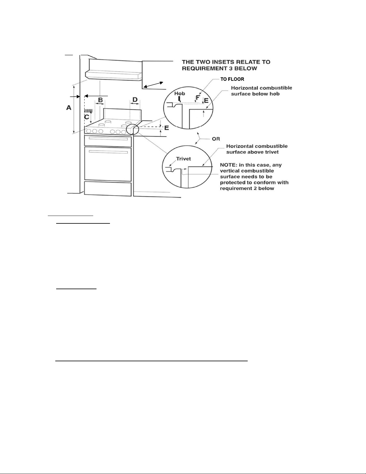
Clearance above and around domestic cookers
REQUIREMENTS
1. Overhead clearances – (Measurement A)
Range hoods and exhaust fans shall be installed in accordance with the
manufacturer’s instructions. However, in no case shall the clearance between the
highest part of the hob of the cooking appliance and a range hood or an overhead
exaust fan be less than 700 mm .
Any other downward facing combustible surface less than 700 mm above the
highest part of the hob shall be protected for the full width and depth of the cooking
surface area in accordance with clause 5.12.1.2. However, in no case shall the
clearance to any surface be less than 450mm.
The maximum depth of wall cabinet above the cooking shall be 400 mm.
2. Side clearances – (Measurements B & C)
Where B, measured from the periphery of the nearest burner to any vertical
combustible surface, is less than 200 mm, the surface shall be protected in
accordance with Clause 5.12.1.2 to a height C of not less than 200 mm above the
level of the backguard for the full width of the cooking surface area. Where the
cooking appliance is fitted with a “splash back”, protection of the rear wall is not
required.
The appliance can be installed between two walls. A single sidewall that exceeds the
height of the work surface is possible. This must be at a minimum distance of 70 mm
from the edge of the cooker.
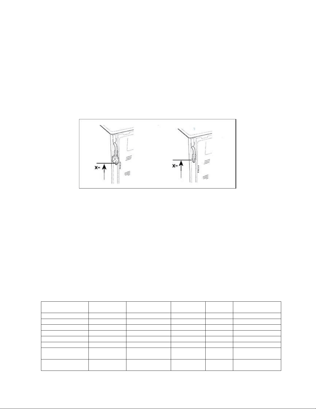
3. Additional requirements for Freestanding and Elevated Cooking Appliances – (Measurements D, E & F)
Where D, the distance from the periphery of the nearest burner to a horizontal
combustible surface is less than 200 mm, then E shall be 10 mm or more, F
distance from pan supports level to floor shall be from 908 mm MIN to 933 mm max,
or the horizontal surface shall be above the trivet. See inserts above.
70mm
400mm max.
6
IMPORTANT INFORMATION FOR INSTALLING AND SERVICING THE
APPLIANCE
The cooker can be installed separately, as a freestanding unit, or between kitchen units or between a
kitchen unit and the wall.
This appliance is not connected to devices which exhaust combustion products.
Special attention must be focused on the prescriptions described below regarding room aeration and
ventilation.
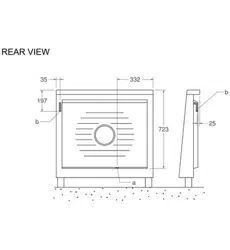
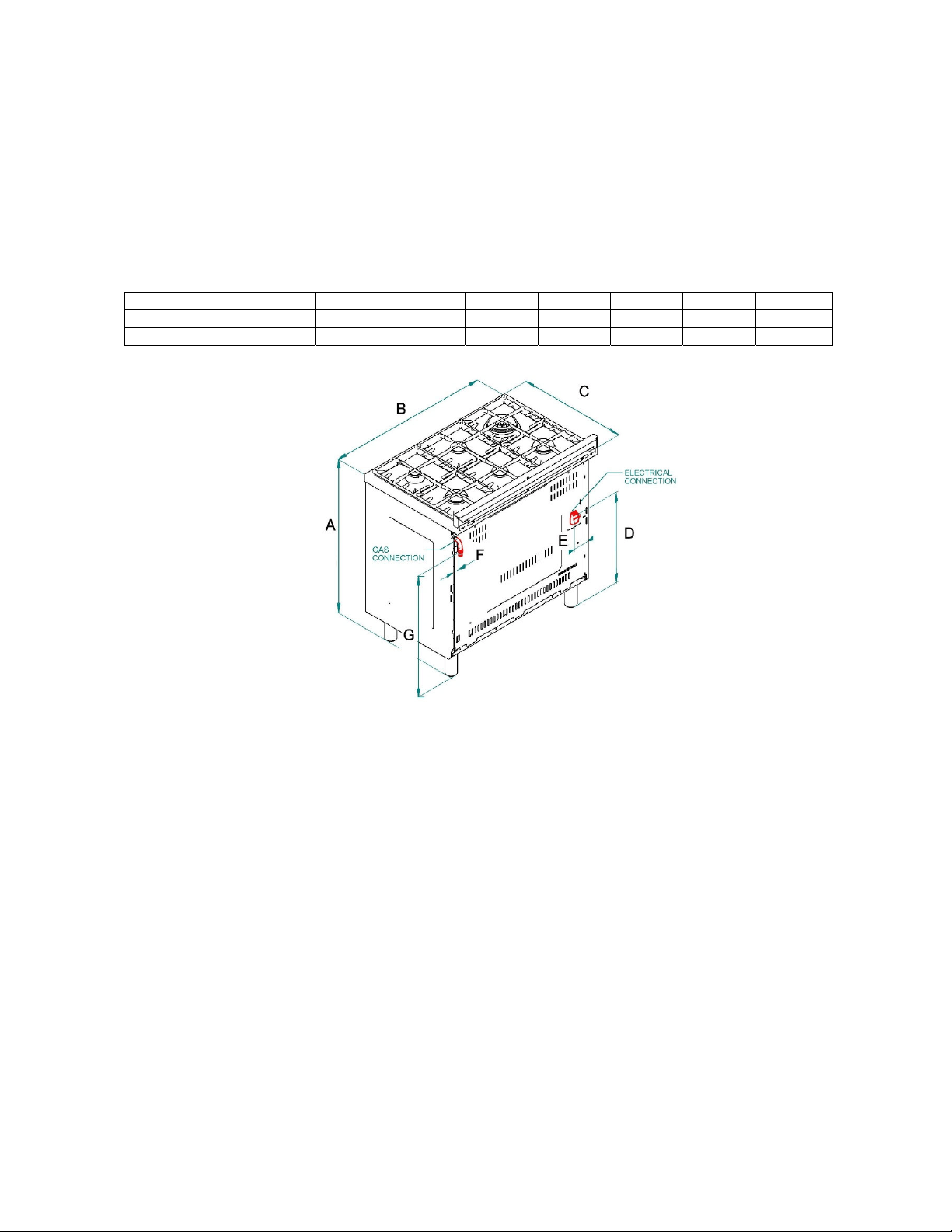
The dimensions of the appliance are listed below:
Cooker model A
(
mm
)
B
(
mm
)
C
(
mm
)
D
(
mm
)
E
(
mm
)
F
(
mm
)
G
(
mm
)
90 sin
g
le oven 892-917 895 600 188-213 333 35 681-706
120 twin oven 892-917 1195 600 188-213 63 35 681-706
7
APPLIANCE SERVICING
IMPORTANT!
ALL SERVICING AND MAINTENANCE ARE TO BE COMPLETED BY THE MANUFACTURER’S
AUTHORISED PERSONNEL ONLY.
Before carrying any servicing operation disconnect the appliance from gas and electric supply and extra
appliance from final installation place in order to have access to the appliance for proper servicing
intervention.
STEP 1: PRESSURE REGULATOR.
For NG or ULPG installation ref. to fig. 7 and chapter ‘Appliance gas connection’ 7
STEP 2: SURFACE BURNERS
For surface burners conversion ref to table 1 chapter ‘Adaption to various types
of gas’ and chapter ‘Conversion to different types of gas’
STEP 3: VISUAL CHECKS
The following visual check must be performed to ensure that the conversion has
been carried out properly and without damage to other components of the range.
Verify that the flame of the oven burner be completely blue and with regular aspect
as shown below.
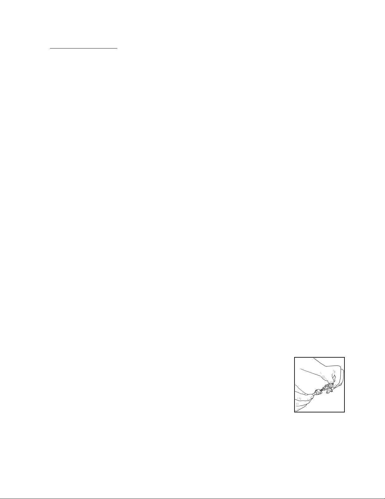
CONNECTION OF THERMOCOUPLE TO THERMOSTAT
The thermocouple for oven burner is connected to the magnet. Tight gently the connection.
The tip of the spark plug or thermocouple must fully overlap at least the first gas emission hole of the burner.
After performing all these visual checks, reinstall the bottom panel of the oven compartment and proceed
to setting the minimum for each burner.
STEP 4: MINIMUM FLAME ADJUSTMENT
WARNING!
These adjustments should be made only for use of the appliance with Natural gas.
For use with ULPG, the bypass screw must be fully turned in a clockwise direction.
Surface burners
Light one burner at a time and set the knob to the MINIMUM position (small
flame). Remove the knob.
The range is equipped with a safety valve. Using a small-size slotted screwdriver,
locate the choke valve on the valve body and turn the choke screw to the right or
left until the burner flame is adjusted to desired minimum.
Make sure that the flame does not go out when switching quickly from the
MAXIMUM to the MINIMUM position.
Greasing the valves
If it becomes difficult to operate the valve, it should be greased immediately by
following the instructions listed below:
1) Disassemble the valve body by loosening the two screws located on
the body of valve.
2) Extract and clean the seal cone and its housing with a cloth.
3) Lightly grease the cone with special grease.
4) Insert the cone, moving it several times, remove it again, remove the
excess grease and make sure that the gas passage ways are
unobstructed.
5) Replace all the pieces by reversing the order in which they were
disassembled and check that the valve operates correctly.
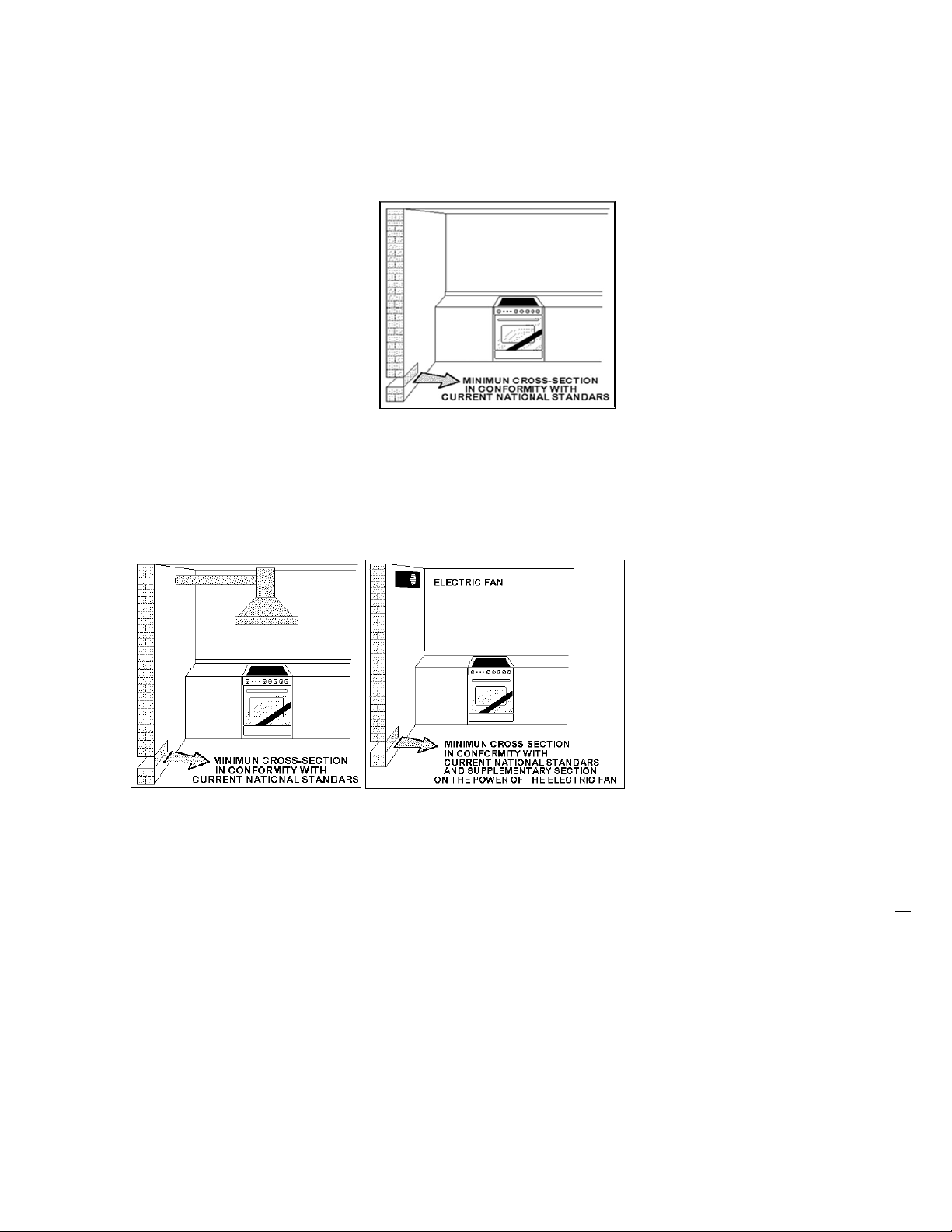
Room Ventilation
To ensure that the appliance operates correctly, the room where it is installed must
be continuously ventilated. The room volume should not be less than 25m3 and the
quantity of air should be based on the regular combustion of gas and on the
ventilation of the room. Natural air will flow through permanent openings in the
8
walls of the room to be ventilated. These openings will be connected with the
outside environment and should have a minimum cross-section defined by current
national standards regarding room ventilation (Fig. 04).
These openings should be built so that they cannot be clogged.
Indirect ventilation is also permitted by taking air from the rooms adjacent to the one
to be ventilated.
Fig.04
Location and Aeration
Gas cooking appliances must always evacuate the combustion products by means
of hoods connected to chimneys, flues or directly outside (Fig. 05). If a hood cannot
be installed It is possible to use a fan installed on a window or directly facing
outdoors, to be operated together with the appliance ( Fig. 06), provided that there is
strict compliance with the ventilation regulations.
Fig. 05 Fig. 06
9
APPLIANCE GAS CONNECTION
IMPORTANT: This appliance must be installed by an authorised person.
WARNING: DO NOT MODIFY THIS APPLIANCE
If the appliance cannot be adjusted to perform correctly, contact the service department.
This appliance utilises a threaded 1/2" gas male fitting.
To connect the appliance to the gas network with a flexible hose, a supplemental hose nipple fitting is
needed which is supplied with the appliance. (Fig. 07)
Gas inlet (mm) Nat gas Gas inlet (mm) LPG
From RH rear side: 35 mm From RH rear side: 35mm
Up from floor: 596 mm (model 90 and 120) Up from floor: 681 mm (model 90 and 120)
Up from floor: 617 mm (model 100 and 110) Up from floor: 702 mm (model 100 and 110)
Fig. 07
Gas Regulator
The gas connection is via 1/2" tapered thread. Connect the cooker to the gas supply and test for leaks.
NEVER use a naked flame to check for gas leaks.
Natural Gas: Gas regulator supplied with the appliance must be installed. ULPG: Test point adaptor to be
fitted and checked at time of installation.
Using a flexible connection
This appliance is approved for connection with a flexible hose, which complies with the AS/NZS 1869 (AGA
Approved), 10mm ID, class B or D, between 1-1.2m long. Connection shall be in compliance with AS/NZS
5601.
When installing the hose restraint device, the appliance anchor point is the rear panel.
Using a Copper Pipe connection
We recommend that the isolation valve be fitted prior to the cooker to enable isolation of the cooker from
the gas supply. The valve must be easily accessible at all times.
To find out the gas type factory settings, see label on the rear of the appliance.
Adaption to various types of gas
Burners Gas type Pressure (kPa) Injector
(
mm
)
Mj/hr By-pass size (mm)
Small Natural 1.00 0.92 4.20 0.34 re
g
ulated
Small ULPG 2.75 0.56 4.00 0.34
Medium Natural 1.00 1.17 6.60 0.36 re
g
ulated
Medium ULPG 2.75 0.73 6.90 0.36
Lar
g
e Natural 1.00 1.55 11.50 0.52 re
g
ulated
Lar
g
e ULPG 2.75 0.98 12.30 0.52
Wok 2way Natural 1.00
Ex. 2 x 1.14
int.0.80
15.60
Ext. 0.65 reg. int.
0.34 re
g
.
Wok 2way ULPG 2.75
Ex. 2 x 0,73
int. 0.50
17.00
Ext. 0.65
int. 0.34 re
g
.
10
Test the operation of the cooker before leaving
Note: These burners have no aeration adjustment.
Check correct operation of the ignitions system and operation of the regulator and operation of the burners
individually and in combination. Burner flames should be clear blue, with no yellow tipping. If the burners
show any abnormality check that the burners are correctly located. If satisfactory performance cannot be
obtained, contact Bertazzoni Group service.
Important
Before leaving instruct the owner in the use of the cooker it should be expressly noted that we cannot
accept any liability for direct or indirect damage caused by wrong connection or improper installation. When
being repaired, the appliance must always be disconnected from the mains supply; if required, notify our
customer service.
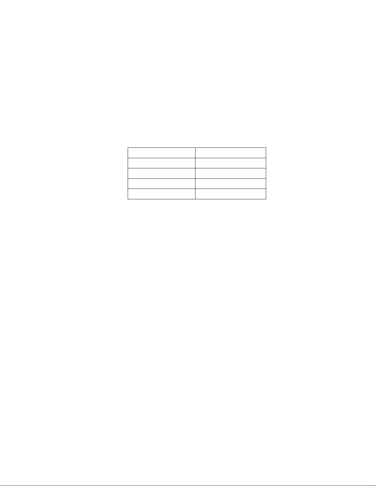
GAS BURNER DIMENSION
Burner Dimension (mm)
Auxiliary Ø 50
Semi-rapid Ø 70
Rapid Ø 95
Wok 2 ways Ø 135
11
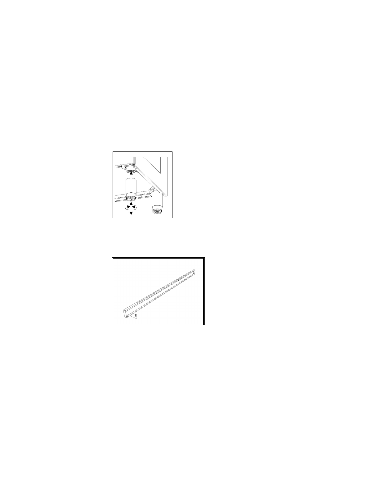
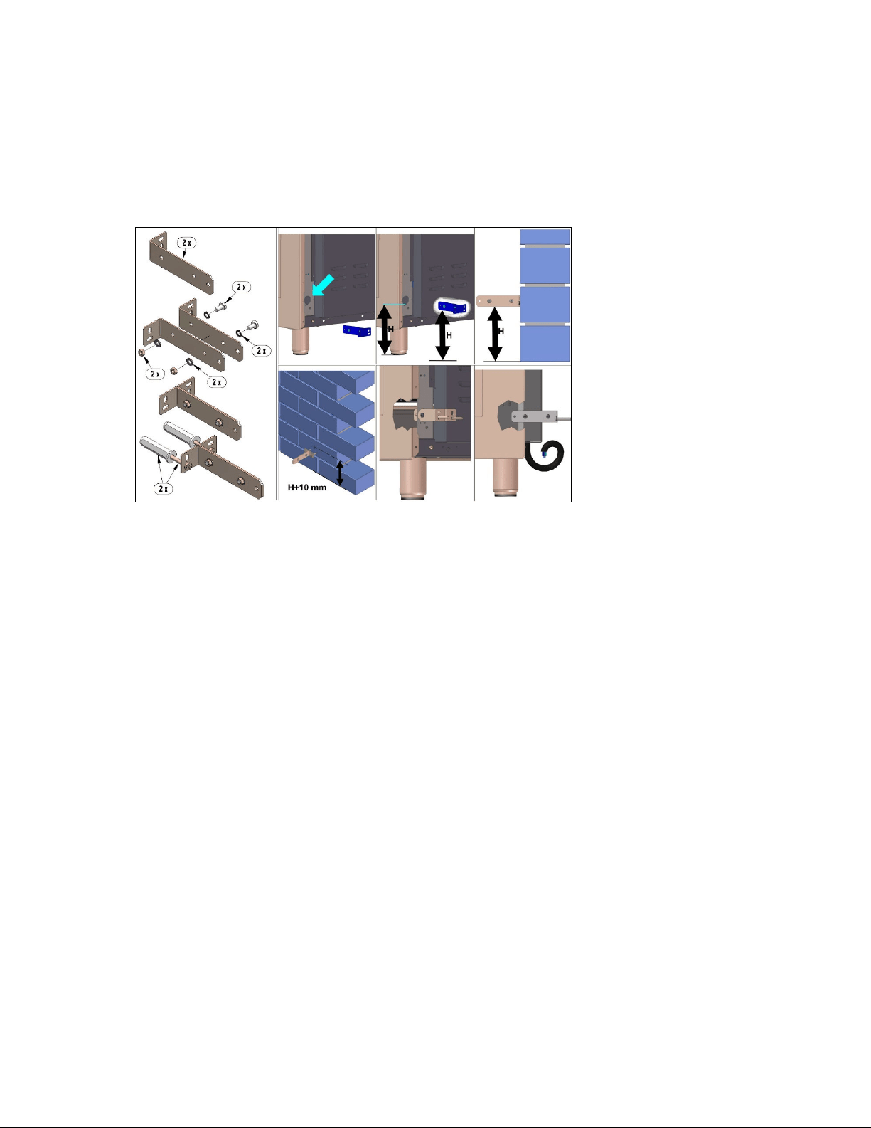
SUPPORT LEGS AND BACKGUARD INSTALLATION
The cookers are supplied with four transit supports (one for each corner).
Four support legs are supplied separately and are fitted on location to the four corners of the lower support
frame. Each support leg is pushed over the relevant transit support until flush with the support frame.
Each leg is adjusted by screwing the lowe r section in or out as required for fitting to a 900mm bench
height. For lower bench tops adjust the height of the legs to 180mm so the hob is located 10mm above
the horizontal combustible surface, ref. AS/NZS 5601.
cooker to keep undue strain from the legs. It is recommended to use a lifting device
instead of tilting the unit.
Transit supports are left in situ. Each leg is firmly pushed over one of the transit
supports. If the legs are not used and the cooker is mounted onto a plinth, leave transit
legs in position to allow for clearance.
Fig 8
Up-stand Installation The up-stand is packaged at the bottom rear of the cooker. The up-stand is fixed
along the rear of the cooker hob. Screw fixing points for locating the up-stand are at
either end.
1. Place the up-stand on the rear of the hob, line up locating holes and secure with
the screws supplied.
Fig 9
12
ANTI-TILT DEVICE AND STRAIN RELIEF FLEXIBLE HOSE DEVICE
ANTI-TILTING CHAIN/HOSE RESTRAINING CHAIN
A chain must be fitted by the installer within 50mm of the hose connection point to
prevent strain on the hose when the cooker is pulled forward. The chain should restrict
the appliance movement to no more than 80% of the hose length. After the chain is
installed, check that there is no strain on the hose or gas connections when the cooker
is pulled as far forward as the chain allows.
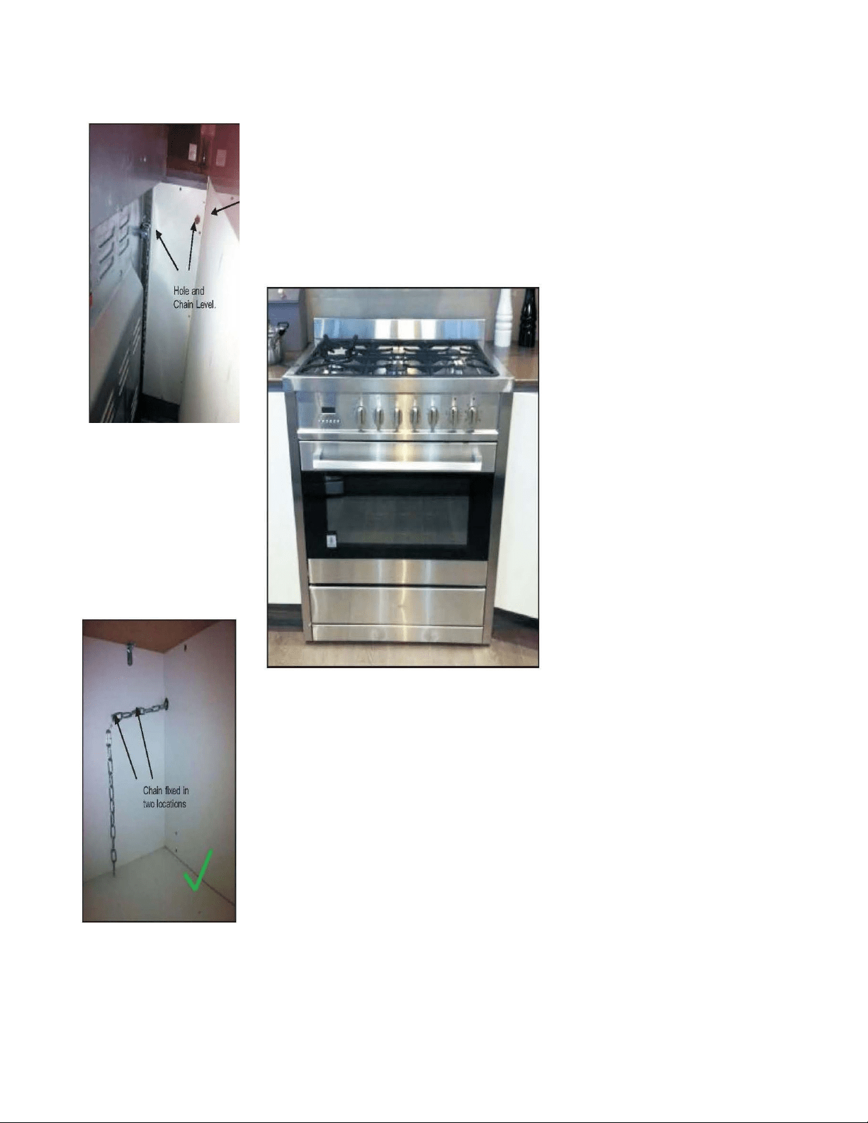
The cooker is also supplied with two chains which are connected to the rear left and
right of the appliance.
The chains should be connected to the wall directly behind the chains as low as
possible to prevent the appliance from tilting forward. If the appliance is installed
between two cupboards, drill a hole on each side of the cupboards, pass the chains
through the holes and anchor the chains within each cupboard. Ensure the chain
connections are strong enough to support the weight of the appliance and taught to
prevent it from tilting forward.
WARNING! In order to prevent accidental tipping of the appliance, for example a child
climbing onto the open oven door, the stabilising means must be installed. Ensure the
chains are correctly anchored to prevent the appliance from tilting forward and to
prevent strain on the hose when the cooker is pulled forward.
MAKE SURE THE ANTI-TILTING CHAINS ARE TAUGHT WHEN ANCHORED AND
ANTI TILT RESTRAINT IS INSTALLED TO PREVENT THE APPLIANCE TILTING
Please refer to the next two pages for examples of incorrect and correct chain
installation.
Accidental tipping
Chains are provided as a
preventative measure against
accidental tipping.
These chains must be fitted as part
of the installers compliance. Failure
for your installer to fit chains in
accordance with the relevant
installation code will make the
installation of your upright cooker
non-compliant and class an illegal
installation.
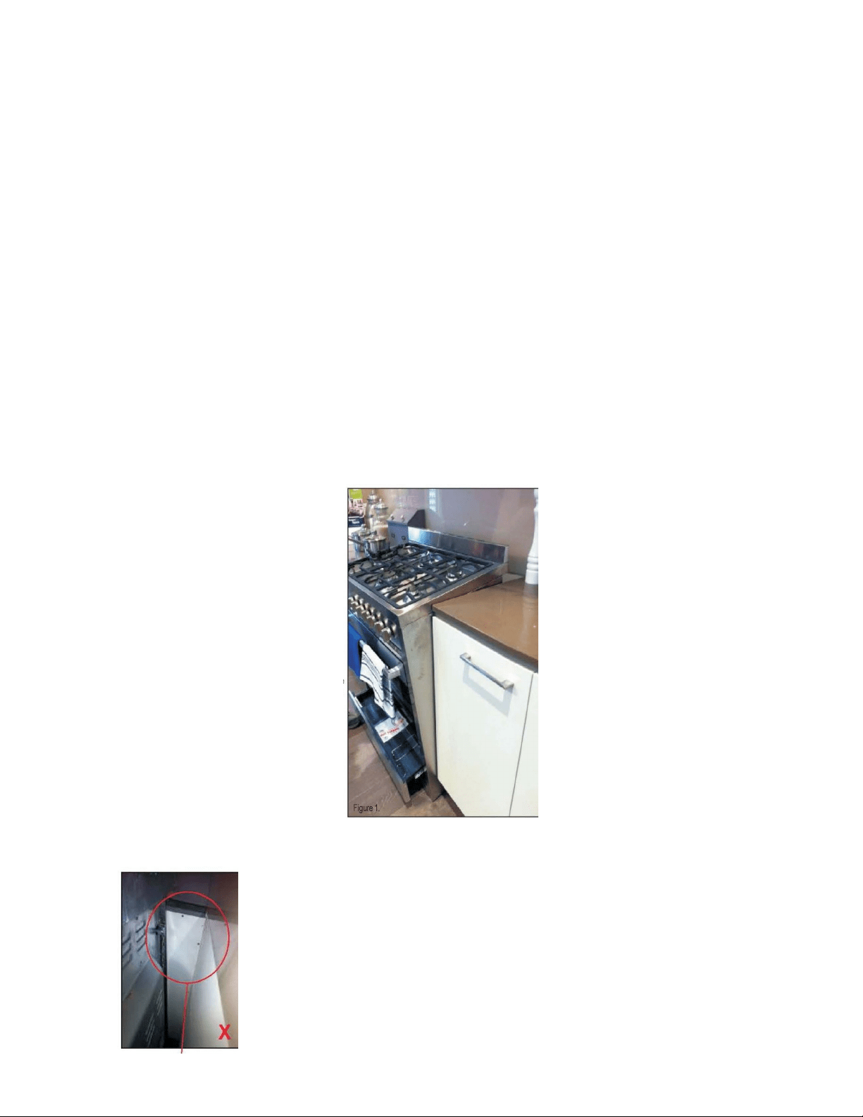
Incorrect installation
The photographs on this page are of
one single kind of incorrect
installation (although there are
many)which does not have the
chains sufficiently secured, figure 1.
Shows an example of how far
forward an oven can tip when not
secured properly. Note: Correct
installation is part of the installer
compliance.
Left Side of oven,
chain not attached
Unfortunately the example on this page is the way many installers are
installing uprights. This may believe that they are using the correct
method by putting the chain through a hole into the adjacent cabinet
and screwing the chain to the back wall but it will not work if not
properly.
Putting the chain into the adjacent cabinet is the preferred method,
provided there is no slackness in the chain.
Some installations only have a single chain affixed. Both chains must
be fixed as part of the installers compliance. Failure to fix both chains
will make the installation non compliant
13
Left Side
In order to prevent the oven from tipping forward as shown on the previous
page, we need to make sure both chains provided with the oven are used.
On the left side of the oven a 16mm drill bit was used to drill through the
cabinetry into the adjacent cabinet, as you can see the hole has not been
drilled hard up against the wall because there is a 16 mm board at the rear
of the cabinet. The heigt of the hole from the floor is level with where the
chain attaches to the oven.
The right side has been drilled much the same, a new hole has been
drilled below the gas and power supply hole
Once the holes have been drilled the chains can be fed trough and the
upright can be fitted into position.
The chains then need to be pulled as tight as possible from inside the
cabinet using a self drilling wood screw. It is better to have the screw fixed
closer to the hole for better support. The left and right side examples shown
have two extra screws attached to the chain which makes the installation
neater by keeping the chain off the shelf away from the gas and electricity
supply, they will also provide added support.
At this point the oven will be secured in location and will not move forward
at all, it is recommended that all upright oven chains be fitted in this way.
Installation forms part of the installer compliance and that in line with AGA
regulations chains are designed to be installed to prevent cooker from
tilting. They are not designed to replace parental supervision when the
cooker is in use.
14
WARNING: In order to prevent accidental tipping of the appliance, for example a child climbing onto the
open oven door, the stabilising means must be installed. Ensure the chains are correctly anchored to prevent
the appliance from tilting forward and to prevent strain on the hose when the cooker is pulled forward.
MAKE SURE THE ANTI-TILTING CHAINS ARE TAUGHT WHEN ANCHORED TO PREVENT THE
APPLIANCE TILTING.
FIG 15
15
CONVERSION TO DIFFERENT TYPES OF GAS
Before performing any maintenance operation, disconnect the appliance from the
gas supply and electricity network.
REPLACING THE NOZZLES TO OPERATE WITH ANOTHER TYPE OF GAS
When converting to ULPG remove the NG gas regulator (if fitted) and fit ULPG test
point adaptor.
If converting to Natural Gas, fit gas regulator
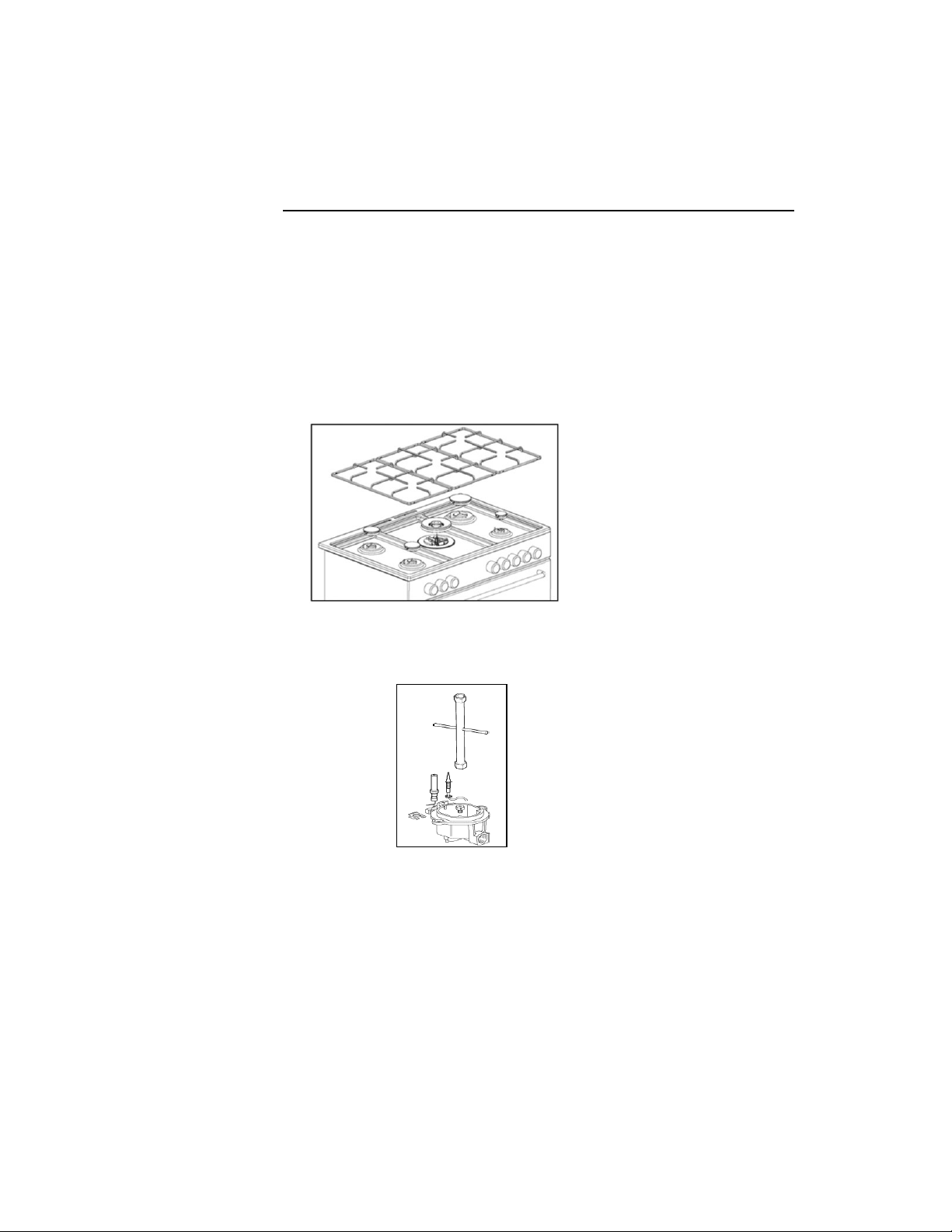
Follow the instructions below to change the burner nozzles on the work surface:
1) Pull out the plug from the electric outlet to avoid any type of electric contact.
2) Remove the grids from the work surface.
3) Remove the burners.
FIG 16
4) Unscrew the nozzles using a 7 mm spanner, and replace them with those needed
for the new type of gas according to what is indicated in the Energy Consumption
Table.
FIG 17
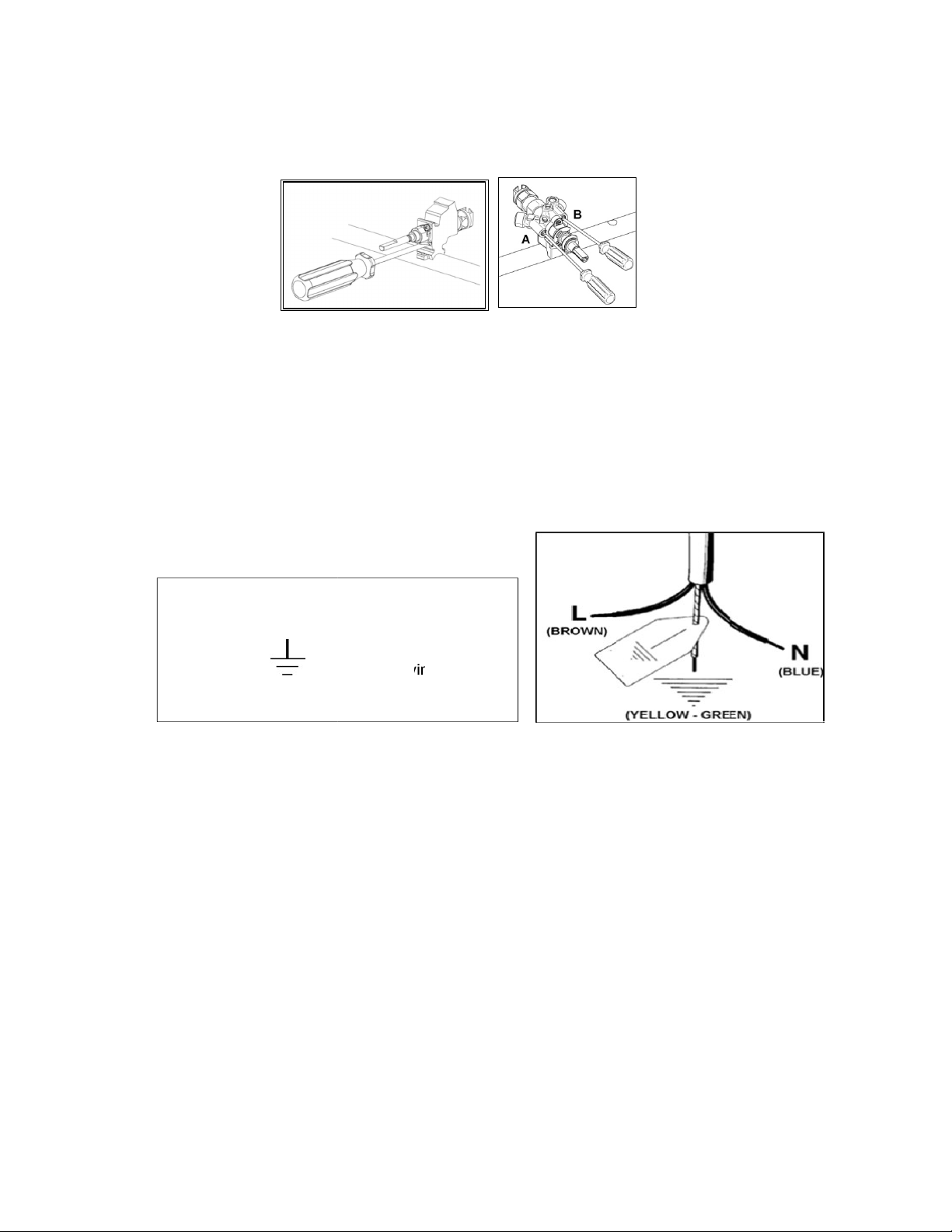
5) Burner "MINIMUM" adjustment:
Work surface burner adjustment: follow the instructions below to adjust the work
surface burner minimum:
Light the burner and set the knob to the MINIMUM position (small flame).
Remove the knob of the valve that is press fit on the rod of that valve.
For all burners except for the wok burner, insert a small slotted screwdriver
into the hole on the valve rod and turn the choke screw to the right or left until the
burner flame is adjusted to minimum.
The wok burner has 2 adjustment screws on either side of the body of the
valve. Screw A is for the outer ring and screw B is for the inner ring. Turn the choke
screw to the right or left until the burner flam e is adjusted to minimum.
Ensure sure that the flame does not go out when s witching quickly from the
MAXIMUM to the MINIMUM position.
16
WARNING: The above-mentioned adjustment should be made only with
natural gas burners, while for those operating with liquid gas the screw must
be locked at the end in a clockwise direction.
APPLIANCE ELECTRICAL CONNECTION
The electric connection must comply with the current legal standards and regulations.
Before making the connection, check that:
•
The system electrical rating and the current outlet are adequate for the maximum
power output of the appliance (see the label applied to the bottom of the casing).
•
The outlet or the system is equipped with an efficient ground connection in
accordance with the current legal standards and regulations. The manufacturer will
not be responsible for the non-compliance with these instructions.
•
The power cord must be positioned so that a temperature of 75°C will not be
reached at any point.
•
Do not use reductions, adapters or splitters since they might cause false contacts
and lead to dangerous overheating.
When the connection is made directly to the electric network:
•
Use a device that ensures disconnection from the mains in which the contacts are
opened to a distance that permits complete disconnection according to the
conditions for over-voltage category III.
•
The ground wire must not be interrupted by the circuit-breaker.
•
As an alternative, the electric connection can also be protected by a high-sensitivity
residual current circuit- breaker but this may be subject to nuisance tripping due to
residual humidity in heating elements.
•
It is highly recommended to attach the special green-yellow ground wire to an
efficient ground system.
WARNING: If the power cord is replaced, the ground wire (yellow-green)
connected to the terminal, should be longer than the other wires by about
2cm.
WARNING: if the supply cord is damaged, it must be replaced by the
manufacturer or its service agent or similarly qualified person in order to avoid
a hazard.
Letter L (phase) =brown wire
Letter N (neutral) = blue wire
Ground symbol =green-yellow wire
17
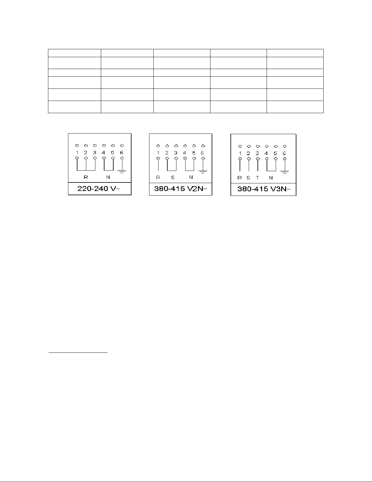
TYPES OF POWER CORDS
Cooker model Type 220-240 V~ 380-415 V2N~ 380-415 V3N~
**90 cm single oven Gas hob top H05RR-F or H05VV-F
3X1,5 mm²
- -
*90 cm single oven Induction hob top H07RN-F 3X4 mm² H07RN-F 4X2,5 mm² H07RN-F 5X1,5 mm²
100 cm XG (3 oven
compartments)
Gas hob top H07RN-F 3X4 mm² H07RN-F 4X2,5 mm² H07RN-F 5X1,5 mm²
*100 cm XG (3 oven
compartments)
Induction hob top H07RN-F 3X6 mm² H07RN-F 4X4 mm² H07RN-F 5X2,5 mm²
120cm twin oven Gas hob top +
griddle
H07RN-F 3X4 mm² H07RN-F 4X1,5 mm² H07RN-F 5X1,5 mm²
* With diversity factor applied
** Supplied with power cord with moulded Australian 3-pin grounded plug rated 15A
The appliance conforms to the regulation AS/NZS 5263.1.1 regarding gas appliance for domestic use and
AS/NZS60335.2.6 regarding safety and CSPR 14 regarding electromagnetic compatibility.
INSTALLATION CHECKLIST
1. Is the range mounted on its legs?
2. Is the backguard securely connected?
3. Has the anti-tip device been properly installed?
4. Does the clearance from the side cabinets comply with the manufacturers directions?
5. Is the electricity properly grounded?
6. Is the gas service line connected following the directions of the manufacturer?
7. Have all the proper valves, stoppers and gasket been installed between the range and the service line?
8. Has the gas connection been checked for leaks?
9. Has the range been set for the type of gas available in the household?
10. Is the ignition of all oven burners functioning properly?
11. Does the flame appear sharp blue, with no yellow tipping, sooting or flame lifting?
12. Has the minimum setting for all burners been adjusted?
13. Does the oven light work properly?
FINAL PREPARATION
Before using the oven, remove any protective wrap from the stainless steel.
All stainless steel body parts should be wiped with hot, soapy water and with a liquid
stainless steel cleanser.
If buildup occurs, do not use steel wool, abrasive cloths, cleaners, or powders! If it is
necessary to scrape stainless steel to remove encrusted materials, soak with hot,
wet cloths to loosen the material, then use a wood or nylon scraper. Do not use a
metal knife, spatula, or any other metal tool to scrape stainless steel! Scratches are
almost impossible to remove.
Before using the oven for food preparation, wash the cavity thoroughly with a warm
soap and water solution to remove film residues and any dust or debris from
installation, then rinse and wiped dry.
18
APPLIANCE USE AND MAINTENANCE
ATTENTION: Important Warnings.
• For cookers resting on base
ATTENTION: if the cooker rest on a base, take the measures necessary to prevent the cooker from sliding
along the support base.
• For cookers with electric ovens
ATTENTION: The unit becomes hot during use. Do not touch the heating elements inside the oven.
ATTENTION: The accessible parts can become hot during use. Keep children away from the appliance.
• For glass doors
ATTENTION: Do not use harsh abrasive cleaning products or metal spatulas with sharp edges to clean the
oven door’s glass since this could scratch the surface and the glass could break.
• For gas cooktops
ATTENTION: Clean burner tops and trivets at least once a week, or after any spillage. Gas inlet pipes
should be checked periodically for leakages (see section on leak testing), at intervals not exceeding 12
months. Lubrication of valves should only be performed by an authorised person, and is required if the
gas control knobs become stiff and difficult to turn.
Do not use steam cleaner to clean the appliance.
WARNING: DO NOT MODIFY THIS APPLIANCE Please maintain your appliance regularly.
REPLACING PARTS
Before performing any maintenance operations, disconnect the appliance from the g
a s supply and electricity network.
To replace parts such as knobs and burners, just remove them from the seats without
dis assembling any part of the cooker.
To replace parts such as nozzle supports, valves and electric components follow the
procedure described in the burner adjustment paragraph. To replace the valve or the
gas thermostat, it is also necessary to disassemble the two rear gas train brackets,
loosening the 4 screws (2 per bracket) that attach it to the rest of the cooker and,
unscrew the nuts that attach the front burner valves to the control support, after
removing all the knobs. To replace the gas or electric thermostat, also disassemble
the rear cooker guard, loosening the relative screws, to be able to pull down and
reposition the thermostat bulb.
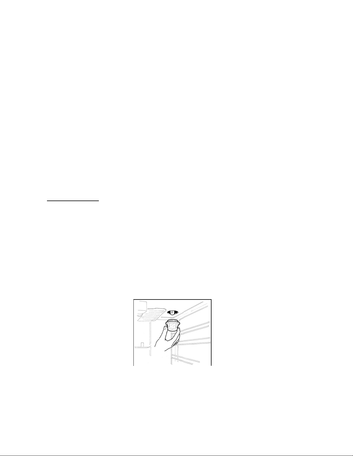
To replace the oven bulb, just unscrew the protection cap that projects out inside the
oven (Fig.22)
Fig.22
WARNING: Ensure that the appliance is switched off before replacing the lamp to avoid the
possibility of electric shock.
WARNING: The power cord supplied with the appliance is connected to the appliance with an X type
connection (in compliance with standards AS/NZS 60335-1, AS/NZS 60335-2-6 and subsequent
amendments) for which it can be installed without the use of special tools, with the same type of cord as
the one installed.
If the power cord becomes worn or damaged, replace it based on the information reported in table 2. To
replace the power cable, lift the terminal board’s cover and replace the cable.

19
GAS HOB
Using the gas hob As the following points:
- To light a burner, press in the control knob (Fig.23-24) and turn it anti-clockwise,
to the large flame position.
- Continue to hold the knob In until the burner lights. Adjust the flame as required,
continue to hold the knob in for 5 to 10 seconds before releasing
- The Griddle (optional) is powered by the gas burners.
- See next page for usage instructions.
Fig 23 Fig 24
The dual wok burner The central burner of the dual wok burner can be used independently of
the outer
burner to give further flexibility.
- To light the central burner, press in the control knob (Fig.25-26) and turn it
anti-
clockwise to the bold single ring position
-
Continue to hold the knob in until the burner lights. Adjust the flame as required
The minimum setting is the lighter single ring position.
- To light the outer burner as well as the central burner. turn the knob to the bold
double ring. Adjust the flame as required
The minimum setting for the central and outer burner is the lighter double ring
position.
Fig 25 Fig 26
Lighting the burners The symbol above each knob indicates which burner that knob controls.
- A flame failure (thermocouple) device on each burner acts as a safety gas cut-off
in case the flame is accidentally blown out.
- A thermocouple detects the absence of a flame and stops the supply of gas.
- The thermocouple must be heated for a few seconds when the burner is ignited
before the knob is released.
To light a burner:
1 Push and turn the control knob anti-clockwise to the large flame
position. The ignition candle will spark and ignite the gas.
2 Keep the control knob pressed In for 5-10 seconds to activate the flame failure
device,
then release the knob. Adjust the flame between the large and small
flame symbols as required.
In the event of a power failure the burners can be lit with a match or gas lighter The
flame failure devices will continue to function normally.
GAS BURNER DIMENSION
Burner Diam (mm) Utilization
Auxiliary Ø 50 mm Use with smaller pans for boiling and simmering and the preparation
of sauces.
Semi-rapid (and
Griddle)
Ø 70 mm Use for normal frying and boiling in medium and small pans.
Rapid Ø 95 mm Use with large and medium pans of water for frying and rapid boiling.
Dual inner/outer Ø 43/140 mm Use with woks,griddles and frying pans or for large pans and rapid
boiling.
20
THE GRIDDLE
Using the Griddle The Griddle is manufactured from 5mm thick stainless steel designed for a high
heat retention across the plate. The very high cooking temperature makes the Griddle
ideal for searing meats and vegetables and for oriental style recipes. Some suggested
uses include: steaks, burgers, chicken, fish and other meats, vegetables such as
peppers, mushrooms and aubergines, stir
fries,
kebabs, toasted sandwiches, naan
and pitta breads, fried and scrambled eggs, griddle cakes, crumpets, English muffins
and drop scones.
To assemble the Griddle:
1 Remove the pan supports that cover the 2 central burners.
2 Screw the feet to the underside of the Griddle. The two longest feet go to the rear
and the two shortest go to the front (towards the drip tray).
3 Carefully position the Griddle onto the hob, ensuring that it is seated correctly and
resting on the stainless hob.
Care must be taken when handling the Griddle. It’s heavy!
Please do not use over dual wok burner
To use the Griddle:
For instructions on how to season the Griddle, see next section. The Griddle can
smoke during use so always turn your extractor hood on before you start cooking.
1 To light the burner. push in and turn the control knob to the large flame position.
Hold the control knob in far 5-10 seconds after the flame has lit to activate the flame
failure device, before releasing.
If the flame extinguishes wait one minute before
attempting to re-ignite.
2 Pre-heat on full power for 5 minutes.
3 Add a small amount of oil and then the food.
4 Adjust the front and back flames as required.
The Griddle is hottest in the central front and back areas and cooler at the outer edges.
You can control the cooking temperature by moving the food to the outer edges after
the initial searing, similar to the way you would use a barbecue. To avoid excess
spitting use the minimum amount of oil when cooking on the Griddle.
Use a spatula for turning and serving food. You can also remove any food residues at
the end of
cooking using a spatula. The high temperature of the Griddle makes plastic
tools unsuitable for use with it. Do not be tempted to move or turn the food too quickly
or often. Wait until the food sears and is released from the cooking surface before
turning.
The following table gives a guide to cooking temperatures and times:
-
These times are purely advisory and will depend on the size and cut of the
food
- Always ensure that food (poultry and fish in particular) is cooked through before
serving.
Food Flame Cookin
g
Fried egg Low 3 minutes
Aubergine, onions and courgettes (sliced 5mm thick) Medium 10 minutes
Whole prawns (shell on) Medium 5 minutes
Chicken breast Low 17 minutes
Fish (200g) Low 15 minutes
Steak (2,5cm thick) High
High
High
Rare 2 minutes per side
Medium 4 minutes per side
Well done 6 minutes per side
Sauté potatoes Medium 5-7 minutes
Burgers, beef, lamb and vegetables Medium 10 minutes

21
Using the electric griddle Seasoning the griddle (and Griddle)
(120cm models only) Before using the griddle for the first time. It must be seasoned.
If the griddle has not been used for a period of time, it should be re-seasoned.
1 Clean the griddle thoroughly with hot. soapy water to remove any protective
coating.
2 Rinse with a mixture 1 litre of water and 1 cup white vinegar .Dry thoroughly.
3 Pour 1 tsp vegetable oil into the centre of the griddle. Rub the oil aver the entire
surface of the griddle using a heavy cloth.
4 Turn the control knob to a maximum setting. Turn the heat off when the oil begins
to smoke. Allow the griddle to cool.
5 Repeat step 3. Be sure to cover the entire surface with the oil.
6 Repeat step 4. Allow the griddle to cool. Wipe the entire surface of the griddle
using a heavy cloth. Apply a very thin layer of vegetable oil. The griddle is now
ready to use.
Using the electric griddle
- Press and turn the knob (Fig.27) anti-clockwise to the selected position.
- Pre-heat at the maximum temperature for 15 minutes, then place the food on the
griddle and cook to the desired temperature.
- The activation of the griddle is shown by the indicator light which is also found on
the front panel of the appliance.
-
Fig 27
Griddle cooking recommendations
Food knob position Setting
Eggs 5 – 6 150°C to 160°C
Bacon; Breakfast Sausage 6 177°C to 190°C
Toasted Sandwiches 5 – 6 160°C to 177°C
Boneless Chicken Breasts 6 177°C to 190°C
Boneless Pork Chops (15mm thick) 6 177°C to 190°C
Ham Slices (15mm thick) 6 177°C to 190°C
Pancakes; French Toast 6 177°C to 190°C
Potatoes; Hash Browns 7 190°C to 205°C
Cast iron griddle A griddle is available as an optional accessory.
To use a griddle:
1 Place the griddle on top of the pan support.
2 Pre-heat the griddle on full power tor 4-5 minutes before adding the food. Most foods
(eggs in particular) will require a small amount of oil to help prevent sticking. Turn the
food half-way through the cooking time to sear both sides. The more the griddle is
used, the better the cast iron will absorb oils, giving it a natural non-stick finish.
22
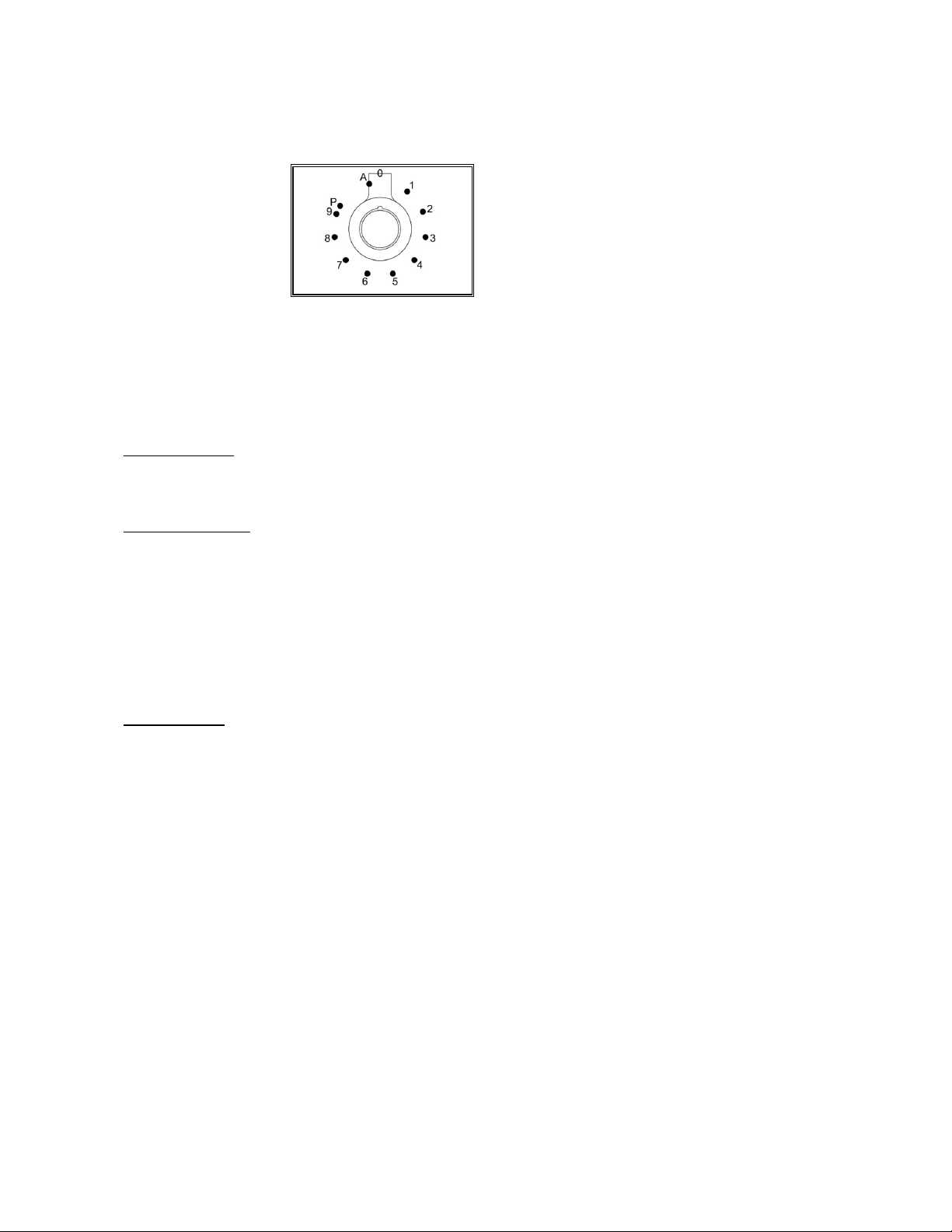
INDUCTION
Fig 28
Functions
1…9 : Power Level
P : Booster
A : Heating Accelerator
Hob control knob These knobs provide control of the ceramic hob's cooking zones.
The zone it controls is shown above each knob. Turn the knob to the right to set the
zone's operating power; the settings range from a minimum of 1 to a maximum of 9.
The working power is shown by a display on the hob.
Heating accelerator Each cooking zone is equipped with a heating accelerator.
This system allows the zone to be operated at peak power for a time proportional to
the heating power selected.
To start the heating accelerator, turn the knob to the left, select setting "A" and then
release. The letter "A" will appear on the display on the hob.
You now have 3 seconds to select the heating setting of your choice. Once a setting
between 1 and 9 has been selected, "A" and the chosen setting will flash in
alternation on the display. '
While the heating accelerator is in operation, the heating level can be increased at
any time. The "full power" time will be modified accordingly. If the power is reduced
by turning the knob anticlockwise, option "A" is automatically deactivated.
Power Function The power function allows the user to operate each heating zone continuously at the
maximum power for a time of no more than 10 minutes. This function can be used,
for example, to bring a large amount of water to the boil in a hurry, or to turn up the
heat under meat.
Turn the knob clockwise and set heating level 9, then use the knob to set the "P"
position and release it. "P" appears on the corresponding zone display.
After 10 minutes, the power is reduced automatically, the knob returns to the 9 setting
and the "P" disappears.
However, the power function can be turned ott at any time by reducing the heating
level. .
When the power function is selected for one heating zone (e.g. the left front zone),
the power absorbed by the second zone (Ieft rear zone) might be reduced to supply
the maximum available energy to the first zone.
Consequently, the power function takes priority over the heating accelerator.
If a pan is removed from the cooking zone while the power function is on, the function
is switched off.
23
HOB
ATTENTION:
Metal items such as cutlery or lids must never be placed on the surface of the hob since they may become
hot.
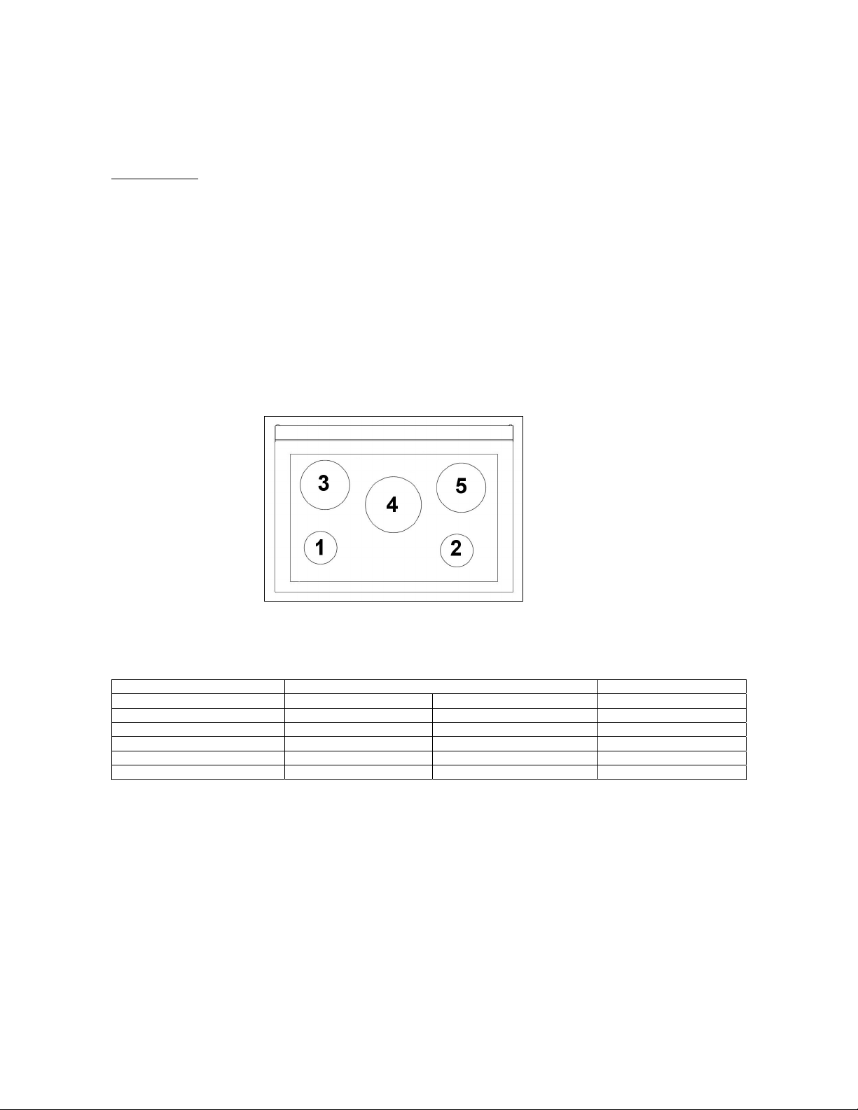
Cooking zones The appliance is equipped with 5 cooking zones having different diameters and
powers. Their positions are clearly marked by rings, while the heating power is only
released in the area shown on the ceramic hob. The 5 cooking zones are of HIGH-
LlGHT type and start to heat up a few seconds after they are switched on. The heat
level of each zone can be regulated from the minimum to the maximum setting using
the knobs on the front panel.
Underneath each cooking zone there is a coil called an inductor, supplied with power
by an electronic system, which generates a variable magnetic field. When a pan is
placed inside this magnetic field, the highfrequency currents concentrate directly on
the bottom of the pan and produce the heat needed to cook the foods.
The 5 lights between the cooking zones come on when the temperature of one or
more cooking zones exceeds 60° C.. The lights go out when the temperature drops
to below about 60° C.
FIG. 29
90x60 model
Power rating (5 zones model)
Zone number: Power absorption Diameter
Normal operation: With power function:
1 1100 W 1400 W 160 mm
2 1100 W 1400 W 160 mm
3 1400 W 2000 W 200 mm
4 2300 W 3000 W 250 mm
5 2300 W 3000 W 200 mm
When the hob is used for the first time, it should be heated to its maximum temperature
for long enough to bum off any oily residues left by the manufacturing process, which
might contaminate foods with unpleasant smells.
24
Types of pans This type of appliance can only operate with pans of special kinds.
The bottom of the pan must be iron or steel/iron to generate the magnetic field
necessary for the heating process.
Vessels made from the following materials are not suitable:
glass;
porcelain;
pottery;
steel, aluminium or copper without magnetic bottom;
To check that a pan is suitable, simply place a magnet close to its bottom:
if the magnet is attracted, the pan is suitable for induction cooking. If no magnet is to
hand, put a little water in the pan, place it on a cooking zone and switch it on. If the
symbol appears on the display instead of the power, the pan is not suitable.
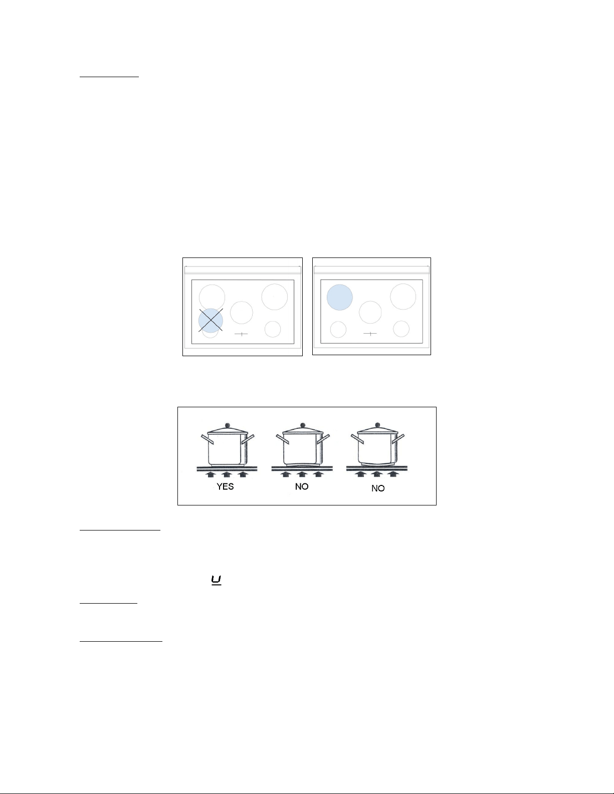
The pans used for cooking must have certain minimum diameters to ensure
satisfactory operation.
Pans larger than the cooking zones can also be used, but it is important to ensure that
the bottom of the pan does not touch other cooking zones, and that it is always centred
over the perimeter of the cooking zone (Fig.30-31).
Fig 30 Fig 31
Use only vessels specially designed for induction cooking, with thick, completely flat
bottom; if these are not available, the pans used must not have crowned (concave or
convex) bottom (Fig.32).
Fig 32
Pan present device Each cooking zone is equipped with a "pan present" device, which ensures that
cooking cannot start unless a suitable pan is present on the cooking zone and properly
positioned.
If the user attempts to switch on the cooking zone with the pan not positioned properly
or with a pan which is not of suitable material, a few seconds after the zone is switched
on the symbol will appear to warn the user that an error has been made.
Residual heat Each cooking zone is equipped with a device which warns of residual heat. After any
cooking zone is switched off, a flashing ‘H’ may appear on the display. This warns that
the cooking zone concerned is stili very hot.
Locking-out the hob When not in use, the hob can be "locked out" to prevent children from accidentally
switching it on.
With the cooking zones off, turn the knobs of zones 1 and 2 to the left simultaneously
until ‘’L’’ appear on the power
display and then release the knobs.
To deactivate it, repeat the same procedure: the cooking zone displays will stop
displaying the ‘’L’’, indicating that the cooking zone lock-out function has been
deactivated.

25
Attention:
Take care not to spill sugar or sweet mixtures onto the hob during cooking, or to place
materials or substances which might melt (plastic or aluminium foil) on it; if this should
occur, to avoid damage to the surface, turn the heating off immediately and clean with
the scraper supplied while the cooking zone is still warm. If the ceramic hob is not
cleaned immediately, residues may form which cannot be removed once the hob has
cooled.
Important!
Keep a close eye on children because they are unlikely to see the residual heat
warming lights. The cooking zones are still very hot for some time after use, even if
they are switched off. Make sure that children never touch them.
WARNING: Under no circumstance use aluminium foil or plastic containers to hold
the food while cooking on a glass-ceramic hob.
WARNING: Do not touch the cooking area as long as the light indicating residual heat
on the glass-ceramic hob, is “on”; this indicates that the temperature in the relative
area is still high.
WARNING: Never place pan with bottoms which are not perfectly flat and smooth on
the hob
WARNING: If you notice a crack in the ceramic hob, disconnect the appliance from
the elettricity supply and contact a service centre
WARNING: Your glass-ceramic hob is thermal shock resistant and resistant to both
heat and cold.
If you drop a heavy pot on your hob it will not break.
On the contrary, if a hard object, such as the salt shaker or the spice bottle strikes the
edge or the corner of the hob, the hob may break.
WARNING: never use the glass-ceramic hob as support surface.
26
SEPARATE GRILL COMPARTMENT (triple oven cavity models only)
The powerful 2.4kW grill can be used for short periods of time (e.g. toast/muffins) with the door open, however
for better efficiency it is recommended that the door is closed. A cooling fan situated behind the control panel
switches on to keep the control knobs at a comfortable temperature when the grill is in use.
The grill pan assembly The grill compartment is fitted with telescopic runners to make it easier to access
your food. To fix the grill pan onto the runners, simply extend both runners, then
lower the grill pan into place, ensuring the back corners of the grill pan rest against
the vertical pins. The wire trivet that fits into the grill pan is reversible to provide two
grilling heights.
To use the grill:
1 Use the reversible trivet to select the correct height for the food you wish to grill.
Using the trivet at the lowest height will help to slow down the cooking process.
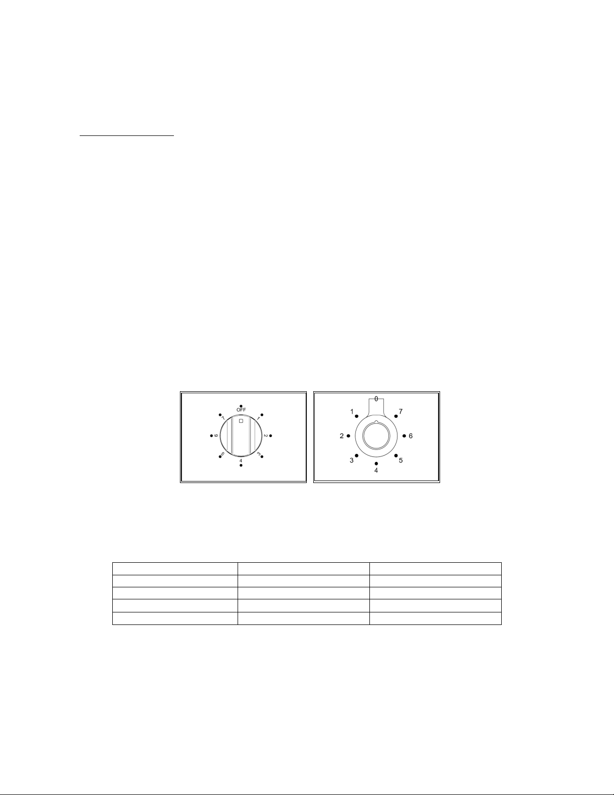
2 Turn the grill control knob (Fig.33-34) clockwise to the maximum setting 7. The
adjacent red thermostat light will illuminate. For best results you should preheat the
grill for 3-5 minutes.
3 Once preheated, adjust the grill control knob clockwise to the desired setting 1 to 7.
4 To turn off the grill, turn the control knob anti-clockwise to the "O" position.
At the end of cooking remove the grill pan for cleaning. If high fat content foods have
been prepared with the door closed, leave the grill turned on at maximum temperature
for 5 minutes. This will burn off any fatty residue on the elements.
Always use oven gloves when handling the grill pan and turning food. Do not line the
grill pan with aluminium foil, this can cause damage to the enamel coating and the
grill elements.
It is recommended to use fan assisted grilling at 200°C
with the door closed in the
main oven for foods that need grilling for longer than 10 minutes (e.g. meat, fish). See
page 30 for more info.
Fig 33 Fig 34
Most foods such as bread products and bacon are grilled on the higher settings For
thicker cuts of meat, chicken pieces etc. you should use fan assisted grilling in the
main oven. See page 30.
Suggested cooking times
(turn the food halfway through the cooking time):
Food Grill setting Cooking time
Bacon High 7 4 – 6 minutes
Toasted bread or muffins High 7 4 – 6 minutes
Crème brulèe High 7 3 – 5 minutes
Crumpets High 7 4 – 6 minutes
27
OVEN
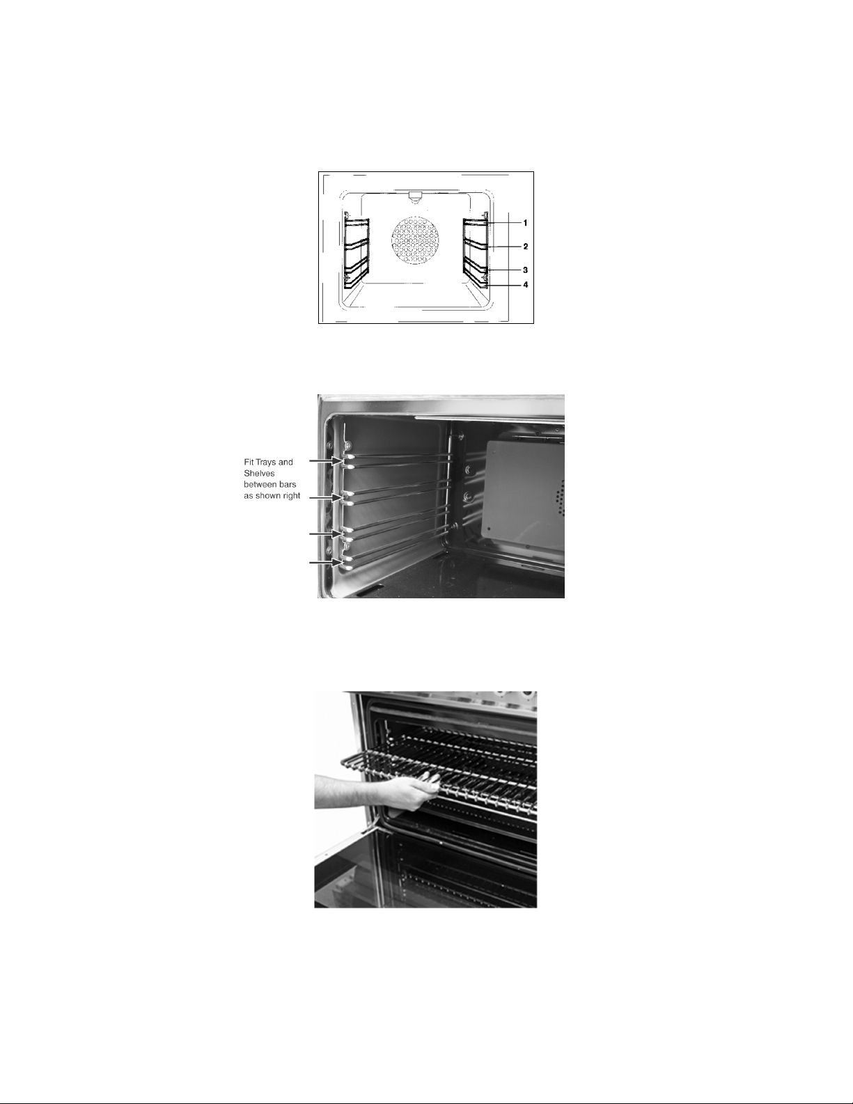
POSITIONING THE OVEN TRAYS & SHELVES
The Grill Tray or Oven Shelf can be located in any of the four height positions in the oven (see image below).
Refer to the ‘Oven Cooking Tables’ for the recommended shelf position. When fitting the trays or shelves, ensure they
are fitted between the two wires that are closest together (see image below).
Oven Shelves have a stop so that they are not fully withdrawn by accident. To fully remove the Oven Shelves, lift the
front of the shelf slightly and withdraw fully from the oven. (see image below) Note that the Grill Tray does not have a
stop position and can be fully withdrawn without interruption, so be careful not to accidentally fully withdraw the tray.
28
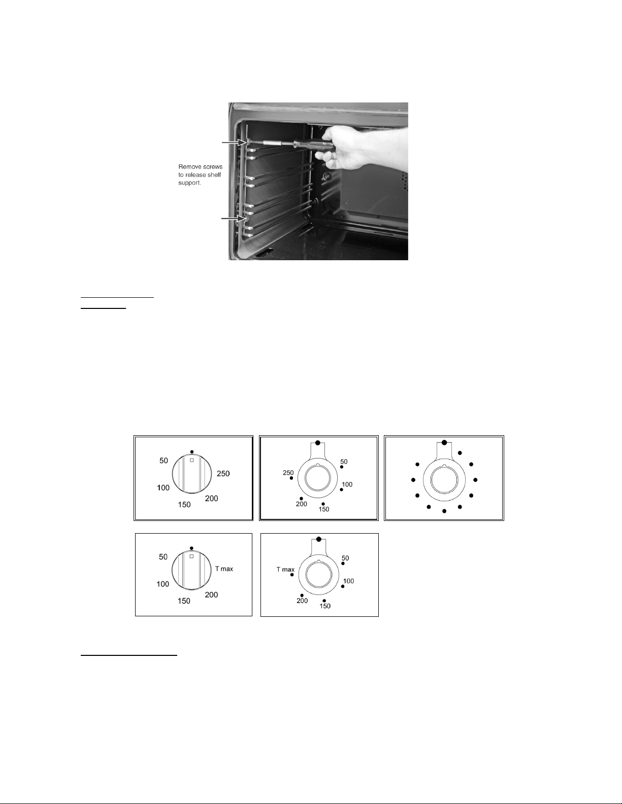
To remove the Oven Shelf Support, remove the top and bottom screws shown below and then pull the support from the
holes in the rear oven wall. Repeat for opposite side. Replace in reverse procedure.
OVENS
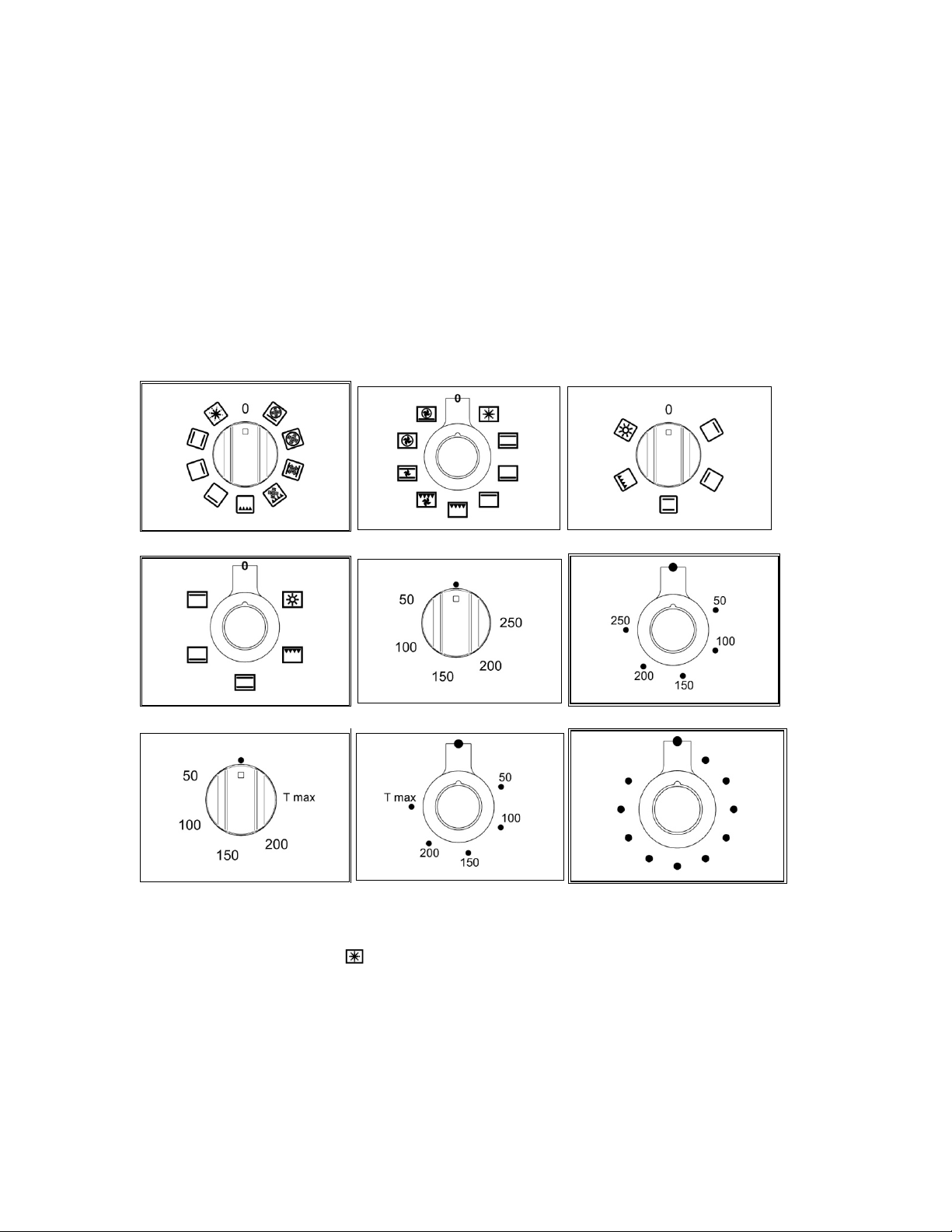
Using the electric The maximum oven temperature can vary according to the tolerances of the different
thermostat materials and installation conditions between 220-250°C.
The thermostat supplied with the relative models maintains a constant temperature
inside the oven at a specific temperature setting ranging from 50°C to 250°C (Fig.
39-40 and Fig.41 for pro t version only ) or 50°C to T max°C for hybrid version
only (Fig.42-43). Turn the knob clockwise and align the selected temperature
indicated on the ring with the index etched on the control panel. Thermostat operation
is indicated by an orange light which will turn off when the temperature inside the oven
is 10°C greater than the temperature setting, and will turn on when the oven is 10°C
less than the temperature setting. The thermostat can control the oven elements only
if the relative switch is in one of the possible oven element operating modes: if the
switch is in position 0, the thermostat has not effect on the oven elements, which
remain off.
Fig 39 Fig 40 Fig 41
Fig.42 Fig.43
Using the electric oven Before using the ovens for the first time:
- Remove all packaging and accessories from inside the ovens.
- Heat the ovens to 200°C for
½ hour to burn off
manufacturing residues.
- The automatic programmer must be set to Manual mode for ordinary cooking.
- The oven will not function when set in Automatic mode. See page 32.
To use the ovens:
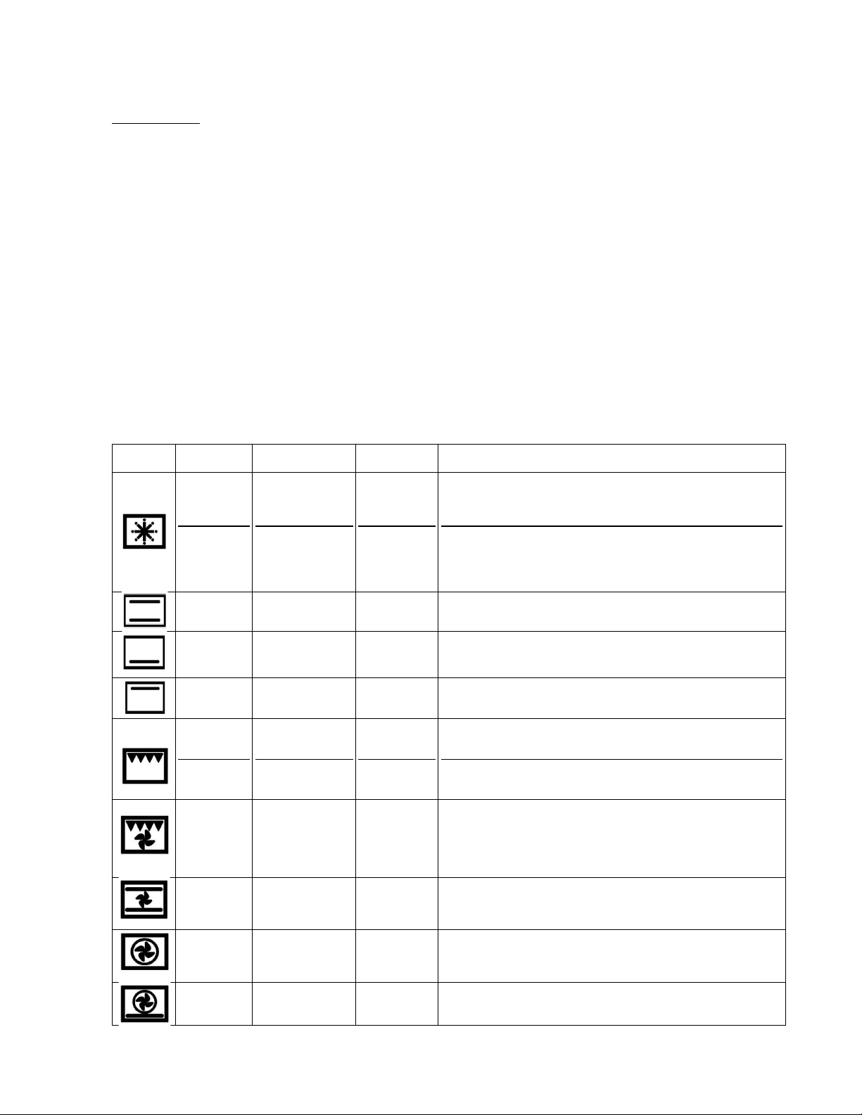
1
Turn the function selector knob (Fig.44 -45 and Fig.46-47) clockwise to the desired
function.
The orange light will illuminate, indicating that the element is on.
29
2
Turn the temperature selector knob (Fig.48-49 and Fig.52 for PRO T version
Only or Fig.50 -51 for hybrid version only)
clockwise to the desired temperature.
The orange light will go out once the
oven has reached temperature and is ready for use. It is normal for this light to go
on and off during cooking as the elements maintain the temperature (The operation
of the oven is indicated by the display of the programmer for PRO T version only).
3
To turn the oven off
,
turn the function selector and temperature knobs anti-
clockwise back to •.
Steam may be generated when cooking. As a precaution, always open the door in
two stages. First, partially open the door by 100mm for a few seconds to allow the
steam to escape, then open the door fully. Keep your face and head away from the
door when opening.
Never line the oven interior with foil as this can cause overheating and damage the
enamel. Never cook on the oven base. Always place dishes and trays onto an oven
shelf. Do not leave the grill pan or other dishes on the oven base as damage to
the oven may occur.
Fig 44 Fig 45 Fig 46
Fig 47 Fig 48 Fig 49
Fig 50 Fig 51 Fig 52
Preheating the oven:
' Fast preheat' provides the most efficient and fastest way to preheat the main oven
(left hand oven). It will also ensure your oven cooks evenly. Use ‘ Fast preheat’ as
follows ( ):
1
Select ' Fast preheat ' (using the oven function selector) and the required cooking
temperature (using the temperature selector). Allow the orange thermostat light to
come on and off several times. This allows the temperature to stabilize before
introducing food (The operation of the oven is indicated by the display of the
programmer for PRO T version only).
2 Select the preferred cooking function and place the food in the oven.
3 When preparing heat sensitive foods such as cakes or meringues using the 'True
Fan' function, allow the orange light to come on and off
again several times to allow
the top element to cool slightly.
‘ Fast preheat’ is unsuitable for use as a cooking function It is a quick pre-heat
30
system.
Oven functions When using any of the functions in the multifunction oven (except grilling and
defrosting) it is always recommended that you pre-heat the oven using the
‘Fast preheat’ function, before switching over to your desired cooking function.
When using the Fan Assisted or True Fan oven function, it is advisable to reduce the
oven temperature by 20°C if following a recipe written for a conventional oven.
Check the food often through the latter stages of cooking until you are used to the
cooking times and temperatures.
The ovens have a range of cooking functions providing different heat zones
.
The 'True
Fan' function for instance, is most suitable for cakes
,
desserts and batch baking. The
'
Fan Assisted
'
function gives more browning so is more suitable for roasting meats
and vegetables or frozen potato products.
Example: To cook a turkey:
When cooking a turkey, the grill pan can be used as a roasting
tin
Line the pan with
a double layer of extra wide foil, allowing enough foil to wrap the turkey loosely. It
is
important to allow enough space around the sides and top of the oven for the hot air
to circulate. Make sure that the foil is not touching the sides or top of the oven. In a
60cm oven a turkey of
9
to 11 kg can be cooked. In a 40cm oven a turkey of 6 – 9
kg can be cooked.
The oven light operates on selection of any oven function
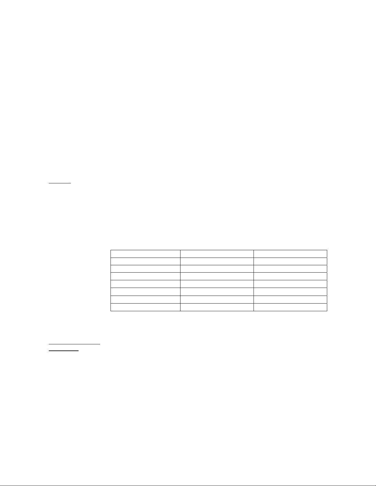
The oven and grill functions are both contained within the one oven compartment and can be used in
conventional mode or with the fan for fan assisted mode. The functions are as follow :
Symbol Function Ovens found in Elements
used
What to use it for
Fast preheat
Defrost
60cm and 90cm
60cm and 90cm
Top plus fan
None
It is recommended that the oven is always pre-heated before use,
whatever the cooking temperature. Fast preheat is not suitable for
cooking - once the oven has reached temperature, switch to one of
the oven functions below.
Place small frozen items on an oven tray at the lowest shelf
position, and set the temperature selector knob to O°C. Never use
heat to defrost as this can pose a health risk. Larger items such as
joints, or a whole chicken or turkey, should be defrosted in the
refri
g
erator.
Conventional
oven
All ovens Top and
bottom
Ideal for roasting and for baking items such as bread or rich fruit
cakes on a single shelf.
Lower
element
All ovens bottom Use at low temperatures for slow-cooking casseroles, custard
or for warming plates. Use at high temperatures for cooking sweet
and savoury pastry tarts.
Upper
element
All ovens Top Use for browning and reheating dishes such as lasagne, moussaka
and cauliflower cheese.
Conventional
grill
Rotisserie
All ovens
30cm and 40cm
Grill
Grill
Ideal for crumpets, muffins and Welsh rarebit. Use when grilling for
less than 15mins. For foods needing a longer time use fan assisted
grilling.
The rotisserie motor rotates food under the grill for succulent
results. Suitable for poultry, game birds and rolled and tied joints of
pork or lamb.
Fan assisted
grill
60cm and 90cm Grill plus fan The fan circulates hot air around the food helping to cook it all the
way through. Ideal for cooking meat such as sausages and chicken
portions. Cooking high water content foods such as bacon and
chops with this function helps to reduce condensation.
(Recommended: Door closed 200°C, 2nd from top shelf, turn the
food over halfway through.
Fan assisted
oven
60cm and 90cm Top and
bottom plus
fan
The fan circulates the hot air around the oven for uniform cooking of
larger quantities of food. Use for roasting vegetables, meat and
poultry, or baked fish. This function is the best one for cooking
frozen potato products and breaded/battered chicken or fish.
True fan
oven
60cm and 90cm Circular fan
element only
This function is suitable for most recipes and is an efficient way to
cook. The temperature is kept uniform throughout the oven and is
particularly suitable for baking on several shelves or for batch
cookin
g
.
Pizza 60cm and 90cm Bottom plus
others
Use for cooking pizza
,
pastry or flat breads to get a
perfectly cooked base.
31
Using the grill
The grill pan consists of a wire trivet and enamel tray. Place food on the wire trivet. A
lower shelf position can be used to slow cooking down, or the temperature can be
reduced. A detachable grill pan handle is supplied for removing the hot tray.
Both the Fan Assisted Grill and Conventional Grill functions are designed to be used
with the oven door closed. This ensures efficient preheating and even cooking. Use
conventional grill at 150°C max setting and or fan forced grill at 175°C max setting.
When grilling, always pre-heat the grill element for 5 minutes before introducing food.
It is recommended that the grill pan is always removed from the oven when not in use,
as air flow around the oven can be impaired. The grill should be used with the oven
door closed. Use the Fan Assisted Grill function for thicker pieces of meat and when
cooking high water content foods to reduce condensation.
Always use oven gloves when handling the grill pan and turning food. Do not line the
grill pan with aluminium foil, this can cause damage to the enamel coating and the
grill elements.
At the end of
cooking remove the grill pan for cleaning. If high fat content foods have
been prepared, leave the grill turned on at a maximum temperature for 5 minutes to
clean the grill element.
Grill Pan The grill pan should be removed from the oven when not required. If left in the oven
it will block the flow of hot air. This can cause hot spots and could damage the grill
pan and the oven interior. When using in 60cm and 90cm ovens the grill pan can
be used in the top two shelf positions for grilling, or in the bottom two shelf positions
for roasting. When using the grill pan for roasting, the 'True Fan' function should be
used.
When using in 30cm or 40cm ovens the grill pan should only be used in conjunction
with the grill (in the top two shelf positions) or for the rotisserie (in the bottom shelf
position).
Fan assisted grilling
Food Grill setting Cooking time
Chicken places 175°C 30 minutes
Burgers 175°C 18 minutes
Fish fillets 175°C 10-15 minutes
Lamb chops 175°C 15 minutes
Gammon steaks 175°C 15 minutes
Chicken breasta 175°C 30 minutes
Pork chops 175°C 25 minutes
These times are purely advisory and will depend on the size and cut of the food.
Please ensure foods are cooked through before serving (pork, fish and chicken in
particular).
Using the grill or fan For even grilling it is important to preheat the grill before introducing the food. This
grill functions will
ensure good sealing and even browning of the food. It is recommended that the
door remain closed for safety and efficiency when using this function. The separate
grill compartment can be used with the door open if preferred, for short grilling
periods (e.g. up to 15 minutes).
Aluminium foil should not be used to line the oven cavity or grill pan. This can cause
overheating, buckling and cracking of the enamel surfaces.
32
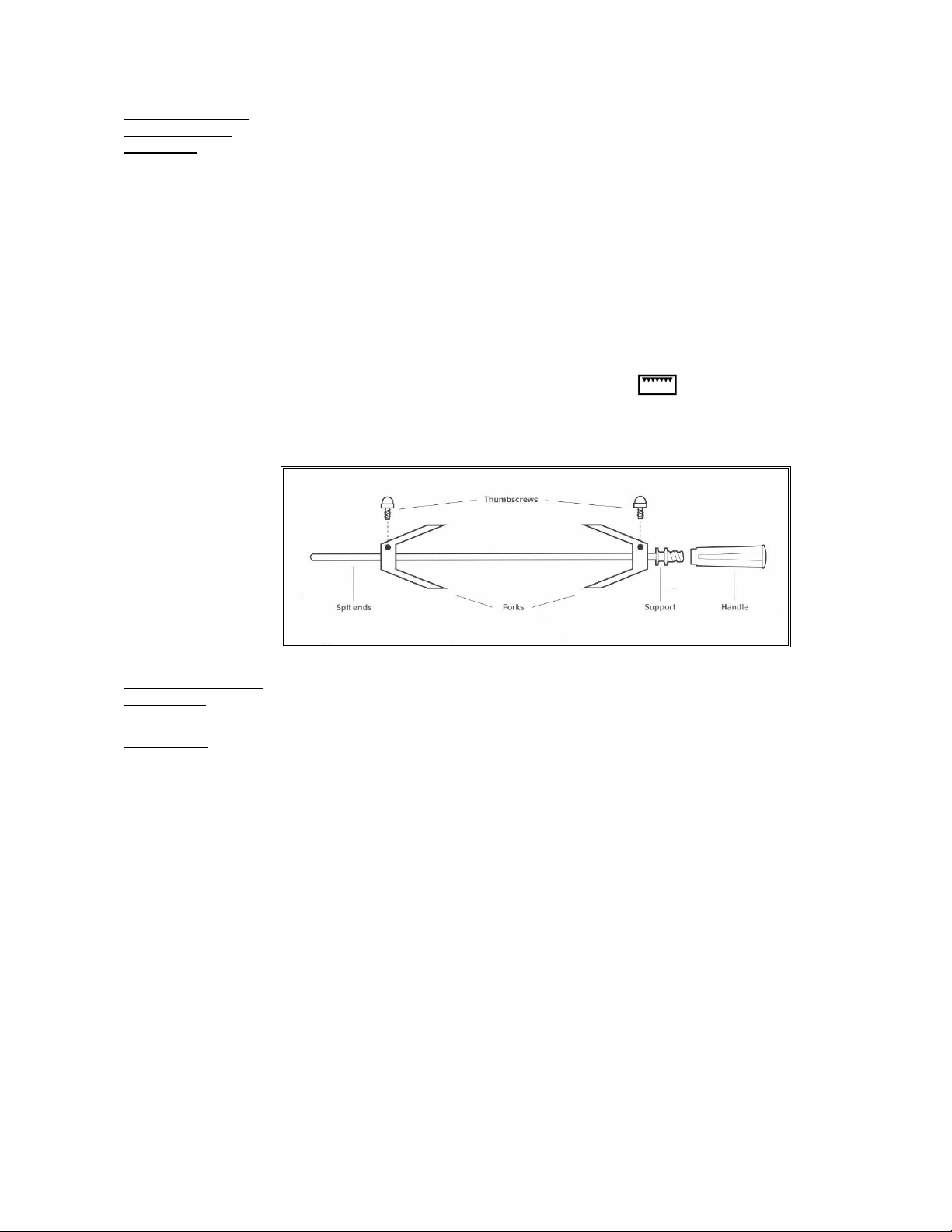
Using the rotisserie Warning: The maximum weight for the rotisserie is 3.5 kg.
(secondary oven 1 Place the grill pan in the bottom shelf position to catch any drips.
TOP model) 2 Place the wire support shelf into the oven so that it sits level with the hole at the
back of the oven.
3 Pre-heat the oven. A temperature of 220
0
C is recommended.
4 Place one of the forks onto the spit and tighten the thumbscrew.
5 Skewer the meat with the spit, ensuring that the fork firmly pierces and holds the
meat. When cooking poultry, aim for the bone area under the breast.
6 Fit the second fork, again ensuring that the meat is firmly pierced. For poultry, the
fork should enter just below the thighs. Tighten the thumbscrew into place. Ensure
that the food is well balanced to avoid stress on the motor drive. The maximum weight
bearing of the spit is 3.5kg.
7 Turn off the oven. Fit the handle to the spit assembly, then place the spit over the
wire support shelf and place the spit end into the hole In the rear oven wall. Locate
the spit support onto the wire shelf. Remove the handle (the handle is used solely for
moving the spit) and close the oven door.
8 Turn the oven back on to the rotisserie/grill function ( ).
As a guide, most meats will require about 15 minutes per 450g at 220°C. Always
check that food is thoroughly cooked and that the juices of poultry run clear when
pierced.
Operating the oven Turn the function selector control knob to switch the light on. The light will remain on
light in the 60cm and while the oven is in use. In the 30cm and 40cm ovens, turn the function control to
90cm ovens the light icon. The light will also operate once a function has been selected for
cooking.
Cooling fan The range cooker is fitted with a thermostatically controlled cooling fan designed to
prevent the control panel and knobs from overheating. The fan will operate when a
certain temperature is reached. It will turn off when the temperature decreases.

33
USING THE AUTOMATIC PROGRAMMER (PRO T model only)
The programmer with touch controls allows to program the cooking cycle with the following cooking tools:
- Delay;
- Cooking time;
- Probe
- Clock or Time
Icons legend
Remove selection or leave menu
Confirm selection
Scroll left/right and up/down (keep press the button to increase
the speed)
Settings menu
System Settings
Timer
Delay
Cooking time
Food probe
Level indicator of temperature
Home screen - To active timer/set up menu touch control zones.
- In this screen the temperature knob is not active.
- To switch directly to the functions cooking selection screen turn the function knob
and the icon of the selected function will appear on the display.
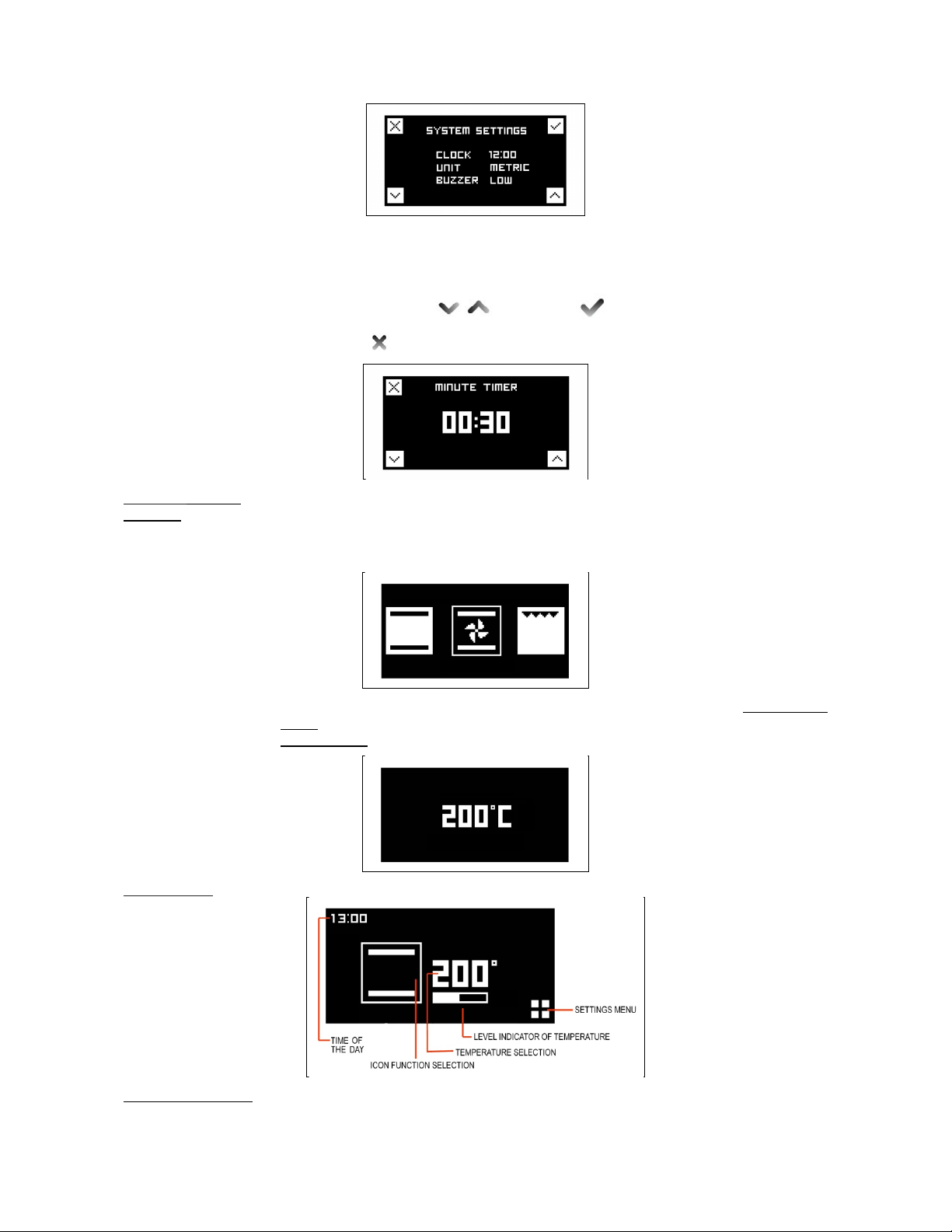
Timer/set up menù To advance to the system settings select the set-up icon.
In this screen it is possible to set the time (12 or 24h), the type of degrees (metric °C
or imperial °F) and the intensity of the buzzer.
Set up
Select field with and confirm
Set the desired values and confirm
Leave menù .
34
Timer
This function is simply a minute minder: the timer can be used independently from
cooking and it will not turn off the oven at the end of the set time. To shut off
automatically the oven, select COOKING TIME (see below).
Set the desired values and confirm
Leave menù .
Functions cooking The display will show the desired function icon turning the function knob
selection In this setting the touch controls are not active.
N.B. the function knob has the priority and the display will always show the choice of
the function.
Choose the desired temperature turning thermostat knob to move to the cooking tools
menu. Wait to 3/4 seconds confirm the selected value and the display will show the
status screen.
Status screen
Cooking tools menu If not selected any cooking instrument after inactivity of 3/5 seconds the screen
returns to the initial state or to status screen in case the oven is in operation.
35
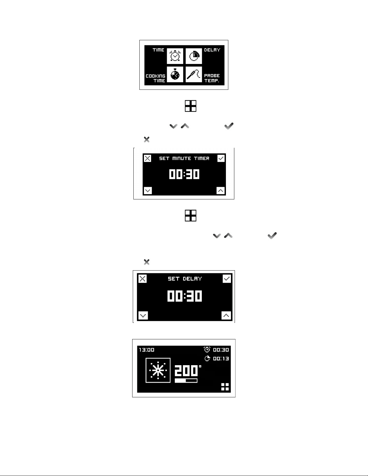
Time
Press the touch zone next to (settings menu) to enter the cooking tools menu
screen and select time touching the corresponding touch control zone.
Set the desired values and confirm
Leave menù .
Delay
Press the touch zone next to (settings menu) to enter the cooking tools menu
screen and select delay touching the corresponding touch control zone.
Set desired time before oven will turn on and confirm
The oven will turn on at the set time and it will be confirmed with a repeating tone.
Touch any touch control area to stop tone.
Leave menù .
After 3/5 seconds of inactivity the screen returns to the status screen.
36
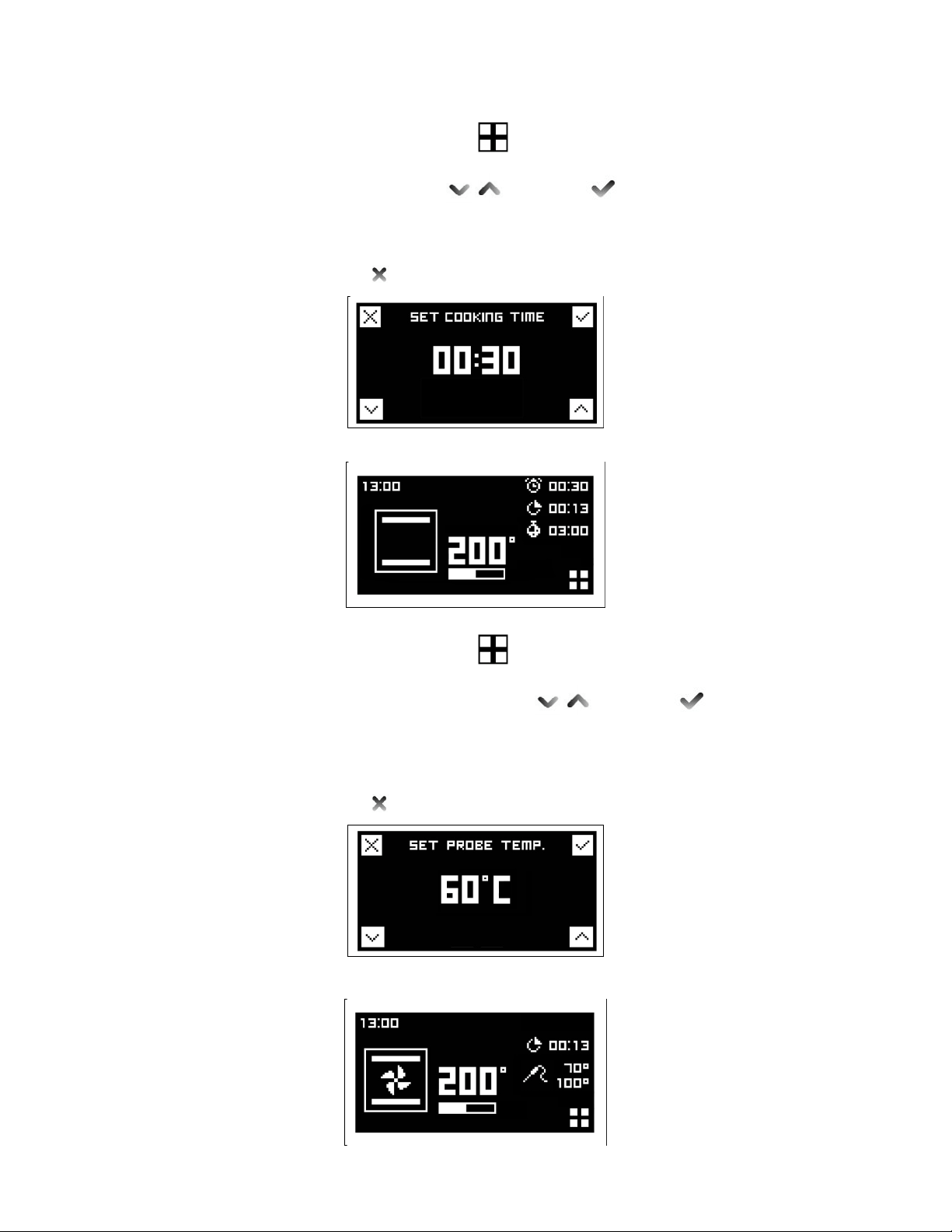
Cooking time
Press the touch zone next to (settings menu) to enter the cooking tools menu
screen and select cooking time touching the corresponding touch control zone.
Set the desired duration and confirm
The display will show the countdown.
The oven will turn off at the end of the countdown and it will be confirmed with a
repeating tone. Touch any touch control area to stop tone.
Leave menù .
After 3/5 seconds of inactivity the screen returns to the status screen.
Probe (PRO T model only)
Press the touch zone next to (settings menu) to enter the cooking tools menu
screen and select probe touching the corresponding touch control zone.
Set the desired food temperature with and confirm .
The display will show the set temperature and the actual temperature measured by
the probe. The oven will turn off when the desired food temperature is reached. End
of cooking will be confirmed with a tone. To stop tone touch any touch control area.
Leave menù .
After 3/5 seconds of inactivity the screen returns to the status screen.

37
The probe works by measuring the temperature inside a joint of meat. There are no
set cooking times as the cooking time depends on how long it takes far the internal
temperature of the meat to reach the set care temperature. This can vary depending
on the weight and type of meat. For this reason it is not recommended that the probe
is used with the automatic timer.
The meat is ready when the temperature set on the right hand side of the clock fascia
is reached and the oven then switches off.
Foods suitable for use with the probe are large joints of boneless meat or joints that
have been deboned & stuffed eg. topside of beef, pork fillet. deboned leg of lamb/pork.
It is important that:
- Meat should be as close to room temperature as possible.
- The probe
is
inserted into the centre of the joint
of meat to give accurate results.
Once in the centre of the meat it is cooked to the temperature selected on the clock
fascia panel.
If the probe is not fully inserted to the centre of the meat, the desired cooking
temperature may not be reached.
To use:
1
Remove the probe part cover on the left hand side of the oven and insert the short
metal end of the probe.
2 Then place the meat in the roasting tin on the 2nd shelf from the base of the oven
and insert the long end of the probe into the thickest part of the meat towards the
centre. Make sure the rubber probe cable is not trapped in the door, or touching the
oven shelf as this could affect the results. Any slack in the cable should rest in the
roasting tin.
3
When both temperatures on the display reach the temperature set, the oven will
switch off.
Below there is a chart to be used as a guideline. Meat cooked this way must not
exceed 2.5kg in weight and should be left at room temperature for a couple of hours
before cooking.
The probe is best used for red meats and pork, as suggested by the guideline
temperatures below. It is not recommended to cook poultry using the probe.
Cut of meat Preferred result Suggested core temp
Topside of beef Medium rare 63°C
Topside of beef Medium 70°C
Deboned leg of lamb Medium pink 69°C
Deboned leg of pork Cooked through not pink 85°C minimum temp
- The meat does not need to rest before carving as it is cooked at a lower
temperature than roasting.
Important
DO NOT LEAVE THE PROBE IN THE OVEN CAVITY WHEN NOT IN USE.
Reset
To reset the cooking tools (delay / cooking time and probe) bring both knobs on the
zero position “0”.
OVEN TEMPERATURE GUIDE
Selecting the correct cooking temperature
The centre of each number should be In line with the central dot icon on the fascia. When using the 'True Fan'
or the 'Pizza' function, select a temperature 20°C lower than your recipe states. Most recipes are written for
the conventional, but, more recently, magazines, food packaging and cook books have started to add the
required Fan temperature, usually in brackets. There are 4 shelf positions – 1 is the lowest and 4 is the highest
near to the grill.
If cooking one dish use shelf position 2, if cooking more than one tray depending on the height of the tray or
food it is suggested to cook on shelf positions 1 & 3.
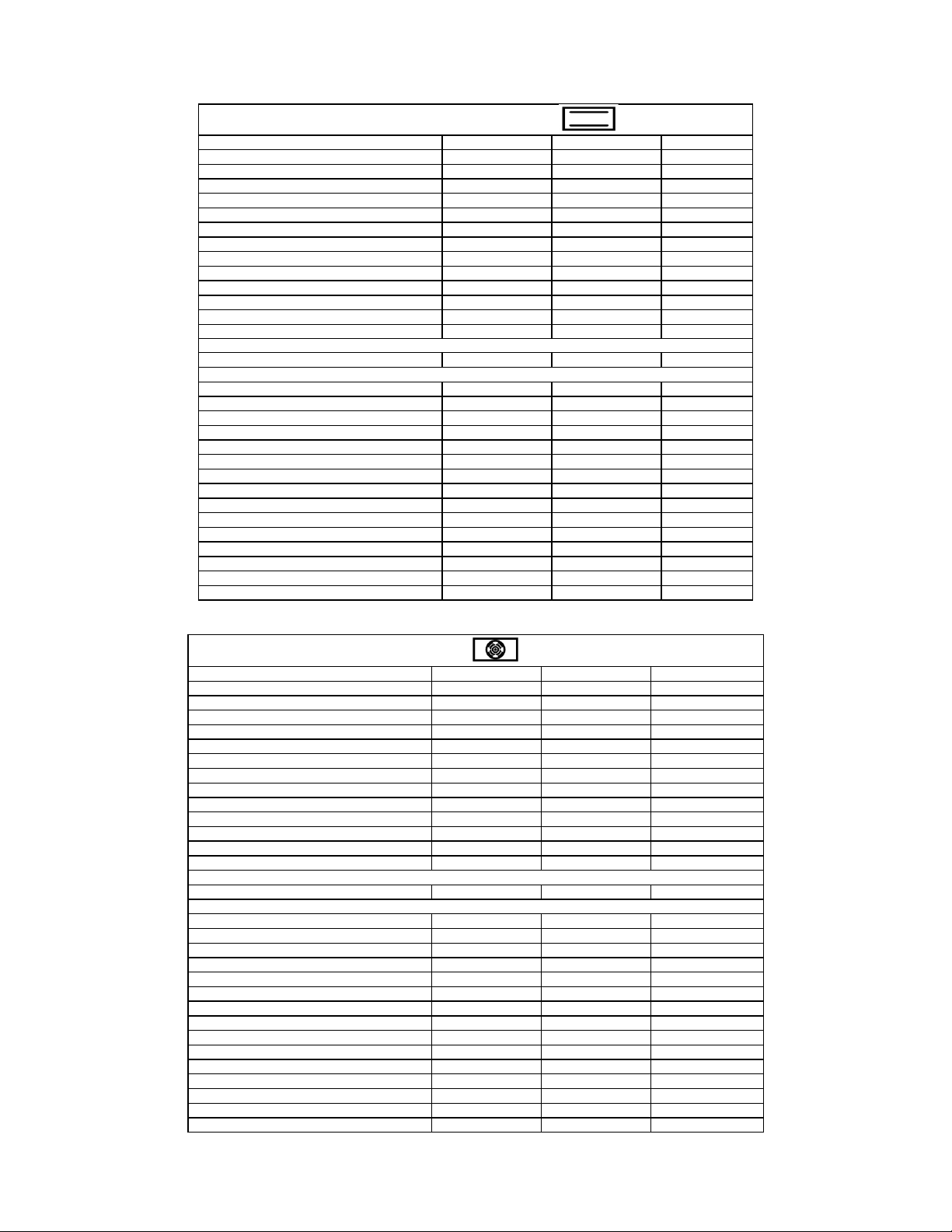
38
NATURAL CONVENTIONAL ELECTRIC OVEN COOKING TABLE
TEMP °C HEIGHT MINUTES
MEAT
PORK ROAST 225 3/4 60-80
BEEF ROAST
(
YOUNG STEER
)
225 3/4 60-80
BEEF ROAST 250 3/4 50-60
VEAL ROAST 225 3/4 60-80
LAMB ROAST 225 3 40-50
ROAST BEEF 230 3/4 50-60
ROAST HARE 250 3/4 40-50
ROAST RABBIT 250 3 60-80
ROAST TURKEY 250 3 50-60
ROAST GOOSE 225 3 60-70
ROAST DUCK 250 3/4 45-60
ROAST CHICKEN 250 3/4 40-45
FISH 200-225 2 15-25
PASTRY
FRUIT PIE 225 2 35-40
TEA CAKE 175-200 2 50-55
BRIOCHES 175-200 2 25-30
SPONGE CAKE 220-250 2 20-30
RING CAKE 180-200 2 30-40
SWEET PUFF PASTRIES 200-220 2 15-20
RAISIN LOAF 250 2 25-35
STRUDEL 180 2 20-30
SAVOIA COOKIES 180-200 2 40-50
APPLE FRITTERS 200-220 2 15-20
SAZOIARDI SANDWICH 200-220 2 20-30
TOAST SANDWICH 250 3 5
BREAD 220 3 30
PIZZA 220 2 20
VENTILATED ELECTRIC OVEN COOKING TABLE
TEMP °C HEIGHT MINUTES
MEAT
PORK ROAST 160-170 2 70-100
BEEF ROAST (YOUNG STEER) 170-180 2 65-90
BEEF ROAST 170-190 2 40-60
VEAL ROAST 160-180 2 65-90
LAMB ROAST 140-160 2 100-130
ROAST BEEF 180-190 2 40-45
ROAST HARE 170-180 2 30-50
ROAST RABBIT 160-170 3 80-100
ROAST TURKEY 160-170 3 160-240
ROAST GOOSE 160-180 3 120-160
ROAST DUCK 170-180 2 100-160
ROAST CHICKEN 180 2 70-90
FISH 160-180 2-3
PASTRY
FRUIT PIE 180-200 2 40-50
TEA CAKE 200-220 2 40-45
BRIOCHES 170-180 2 40-60
SPONGE CAKE 200-230 2 25-35
RING CAKE 160-180 2 35-45
SWEET PUFF PASTRIES 180-200 2 20-30
RAISIN LOAF 230-250 2 30-40
STRUDEL 160 2 25-35
SAVOIA COOKIES 150-180 2 50-60
APPLE FRITTERS 180-200 2 18-25
SAZOIARDI SANDWICH 170-180 2 30-40
TOAST SANDWICH 230-250 3 7
BREAD 200-220 3 40
PIZZA 200-220 2 20
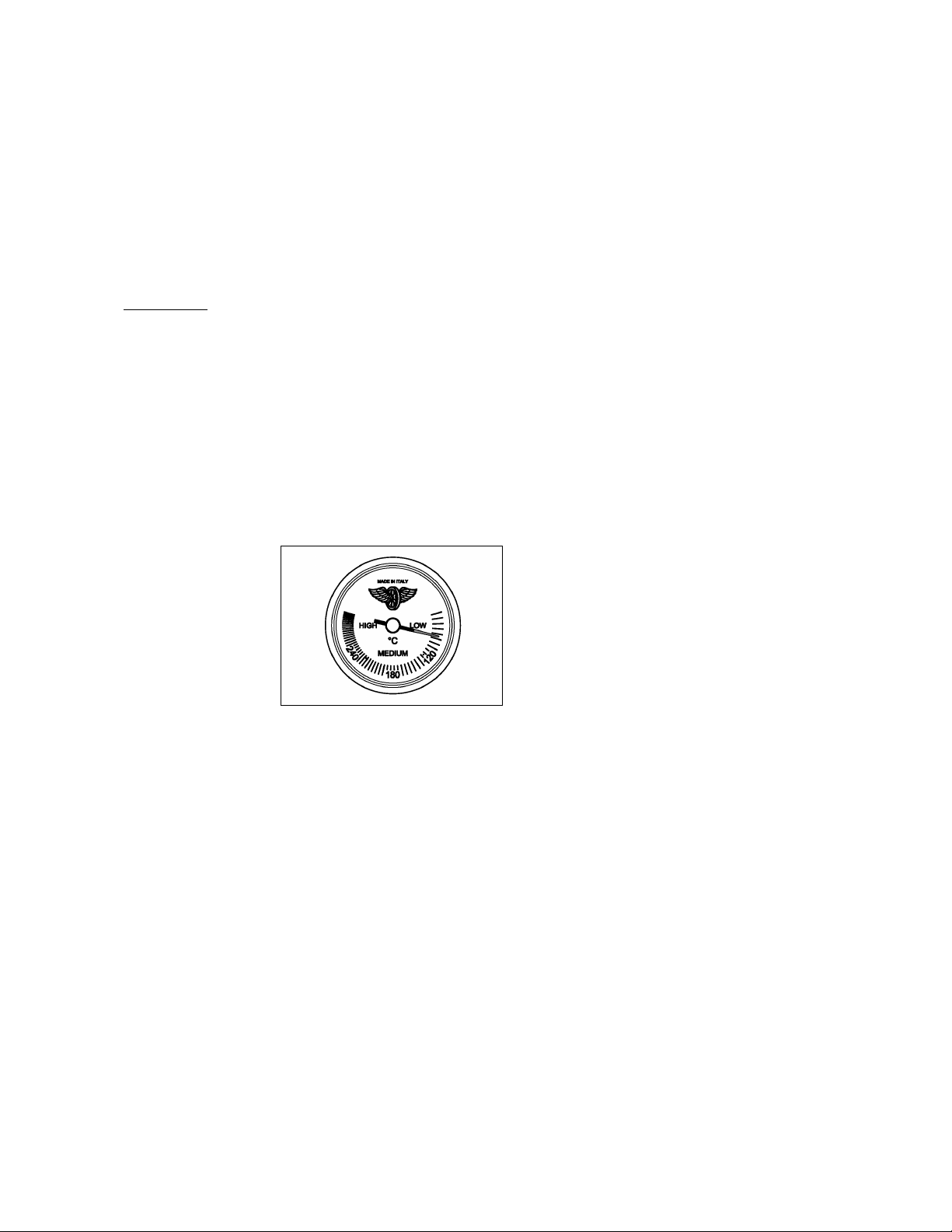
39
When cooking a Dundee cake or rich fruit cake, always wrap 2 layers of brown paper around the sides and
check after each hour.
A piece of brown paper may need to be put over the top. Always ensure foods are cooked through before
serving, pork, poultry and fish in particular .* See page 28 for more information on cooking a turkey.
USING THE THERMOMETER
The cooker is fitted with a device to measure the temperature in the middle of the oven.
This lets you check the temperature inside the oven and adjust food cooking temperatures more accurately.
Electric oven When you turn on the oven, the orange light comes on to indicate that the heating
elements are working: The thermometer dial will start to move towards the set
temperature.
The orange light will keep going on and off, indicating that the heating elements are
working to maintain the temperature inside the oven.
The light may go off for a few minutes before the thermometer has reached the
temperature required. This is normal, because operation of the heating elements is
regulated so that heat is distributed properly inside the oven.
Heat is optimally distributed inside the oven when the thermometer dial has stopped.
If the oven temperature drops or goes up, the thermometer dial will follow these
variations in the same way.
When the oven is turned off, the temperature on the thermometer will slowly drop until
it reaches room temperature.

40
CLEANING YOUR COOKER
A false reading of the temperature may be caused by heavy food soiling, residual oven cleaner on the
thermostat and/or the roof elements, or a dislodged thermostat phial. Cleaning should be carried out regularly
and with care. Always disconnect the electricity supply to the appliance before any cleaning takes place. Never
allow fat or oil to build up on any surface, particularly on oven bases and oven trays, as this can lead to
permanent staining or the risk of fat fires.
Cleaning your gas hob Stainless steel hob
- Do not use any abrasive cleaners on the stainless steel hotplate.
- Wipe with a soft cloth using warm water and washing-up liquid. Whilst still damp
polish dry with an microfibre cloth.
- For stubborn cooked-on stains use a non-abrasive stainless steel cleaner.
- Always work in the same direction as the grain of the stainless
steel,
rinse well
and polish dry.
Pan supports
Pan supports and burner caps are made from cast iron with a protective coating of
acid resistant enamel, and must not be put in a dishwasher.
- Always allow pan supports and burner caps to cool completely before immersing
in water.
- Wipe with a soft cloth using warm water and washing-up liquid.
- For stubborn marks use a cream cleaner applied with a nylon scourer. Rinse
well and dry, before replacing on the hotplate.
- When placing the pan supports on the hotplate, the widest edge of the cast iron
faces to the outside left or right.
Burner rings
- Use a cream cleaner and a nylon scourer. Rinse well and dry.
- After cleaning, ensure that the burner slots are dry and not blocked.
Alloy burner bases
- Never put the alloy bases in a dishwasher as the salt may damage the alloy.
- Always ensure that no other metals are in the same water as the alloy bases as
electrolysis may occur, blackening the alloy. Wipe clean with a soft cloth, warm
water and washing-up liquid.
- For stubborn marks use a cream cleaner on a soft damp cloth.
- Rinse and dry before replacing on the hotplate.
When re-assembling the burners, always ensure that the notches on the burner ring
are seated firmly into the base for the gas to ignite and the flame to be stable. (See
burner assembly instructions
Assembly of the burners (Fig.32)
The circular burners have two notches, which fit around the thermocouple and the
ignition candle (on the dual wok burner these notches are located on the inner ring).
Once the burner is securely in place, the black burner cap(s) should sit on top.
The burner caps must be in the correct position for operation.
Fig 32

41
Griddle
- As the Griddle is heavy we recommend that you clean it on the hob without
moving it.
- After cooking, allow the Griddle to cool until just warm.
- Use a spatula to remove any cooking residue.
- Wipe away any fat in the drip tray with kitchen towel.
- Clean the whole surface with warm water and washing-up liquid, using a
stainless steel scourer. Always work with the grain of the stainless steel.
- Some foods with a high salt content (such as bacon) may leave white rnarks.
For these and other stubborn marks use a cream cleaner suitable for stainless
steel surfaces.
Cast iron griddle
-
The cast iron griddle will absorb oils as it is used. Over time it will develop a
natural non-stick finish.
- After cooking, scour the griddle whilst still warm with warm water, and dry
Immediately.
- Rub a little olive oil into the cooking surface to protect the cast iron while not in
use.
- Avoid using detergents as this will remove the natural non-stick coating. Do not
clean in a dishwasher.
Cleaning your Allow the hotplate to cool down until the residual heat indicator is extinguished
induction hob before commencing any cleaning. Never use scouring powders or paste, metal
scourers, oven cleaners or any abrasive cleaning products on the hotplate. It is
important that any spillage is cleaned from the hotplate before it is used again.
- For light soiling, wipe with a soft cloth, warm water and washing-up liquid. For a
streak free finish, polish dry with an microfibre cloth.
- For more stubborn marks and to condition the surface, use a good quality hob
cleaner/conditioner, following the manufacturer's instructions.
- For spillages with a high sugar content (such as jam) or the accidental melting of
plastic or alloy materials, turn off the hotplate and remove the spillage
immediately. Take care as the hotplate and the spillage will be very hot.
Fascia, controls and external surfaces
Do not use strong or abrasive cleaning agents or materials on the controls. fascia
panel or coloured cooker surfaces This can cause damage to the calibrations and
icons and permanently scratch the surfaces.
Coloured surfaces:
Clean with a sott cloth, warm water and washing-up liquid Whilst still damp, polish dry
with an microfibre cloth.
Stainless steel:
For stubborn marks use a reputable non-abrasive stainless steel cleaner. Always work
with the grain of the stainless steel, rinse well and polish dry with an microfibre cloth.
Glass:
Clean with a soft cloth, warm water and washing-up liquid. Difficult marks on the glass
can be removed using a cream cleaner. Never use sharp implements to remove marks
as this could scratch the glass.
Ovens:
Always allow the oven interior to cool before cleaning.
Interior oven door enamel and glass
Never use sharp implements to remove stains as this could scratch the surface. The
door enamel and glass surfaces can be cleaned with a soft cloth, warm water and
washing-up liquid. Polish dry with an microfibre cloth. For more stubborn marks and
to protect the glass surface use a good quality glass cleaner/conditioner, following
the manufacturer's instructions.
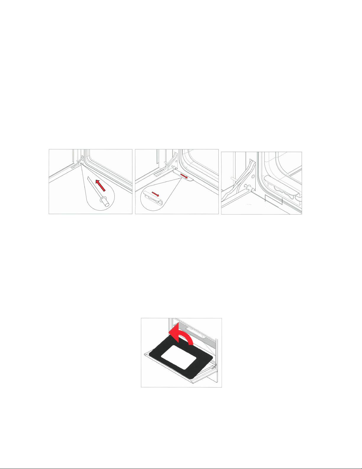
42
Please do not use steam cleaners on the oven interiors as this may damage
electronic parts.
Ensure the cooker is cold before cleaning.
Removal of the oven door (without soft close hinges)
To allow full access to the inside of the oven for thorough cleaning, the oven door can
be removed.
- Fully open the door and insert the pins supplied into each hinge.
- While closing the door to an angle of about 30°, lift and pull so that the door
leaves the mounting. Leave pins in place.
The rivet needs to be put into the hinge before you can remove the door.
Removal of the oven door (with soft close hinges )
- Close the door to an angle of about 30°
- Lift, than close the door to an angle of about 70°
- Pull so that the door leaves the mounting.
The rivet needs to be put into the hinge before you can remove the door.
Removal of the inner glass door panes
To assist with cleaning, the inner glass door panes are removable.
- Open the door fully and insert the pms supplied into each hinge to secure the
door in an open
position.
-
Locate the stainless steel clips at the base of the door.
- Slide the clips towards the centre of the door.
- Holding the glass, lift slightly and pull towards the oven, the glass pane will
release.
- The central glass pane is revealed. This can be cleaned in situ or removed.
- To remove the central pane, remove the 4 screws and brackets.
- It is important to remember when replacing the central pane that the rubber
spacing must be replaced first.
- When replacing the inner pane, ensure the glass is print side up and the widest
border is nearest the cooker.
It is not necessary to remove the door in order to clean the glass panes.
Oven interior
To tell whether your oven has stay clean liners look at the oven walls. If the surface is
grey in colour and rough in texture then this is a stay clean liner.
If the surface is
smooth and black, this is
an enamelled surface.
Fitting the stay clean liners
If you have purchased stay clean liners as an accessory, they are easy to fit.

43
Sideliners
- Remove all shelving from the oven
- Remove side shelf runners by pulling away using the centre of the bottom
runner .
- Place the holes in the side of the liner over the holes in the side of the oven.
- Insert the side shelf runner into the holes starting with the top first, and then
pushing in the bottom.
Back liners (60cm and 90cm ovens only)
- Place hole in centre, bottom of the liner over the hole below the fan at the
Back of
the oven.
- Screw into position.
Cleaning stay clean We recommend that side shelf runners, telescopic runners and shelves are
liners removed prior to cleaning, the stay clean liners and the door and floor are cleaned
by hand.
- After cooking (especially after roasting) remove all trays and shelves.
Heat the oven to maximum temperature for 15 - 20 minutes to allow the stains to
catalyse (true fan or fan assisted functions).
- If the oven is heavily soiled, allow the oven to cool before cleaning the splashes
with a damp sponge. Then heat the oven for two hours at maximum
temperature.
- Repeat the cycle if difficult marks have not been removed.
- Periodically, the side panels can be removed from the oven and washed with
lukewarm soapy water before drying with a soft cloth. Before refitting the
panels, clean the enamel interior.
Enamelled surfaces
Do not allow vinegar, wine, coffee, milk, salt water or fruit juices to remain in contact
with enamelled surfaces for prolonged periods as they may stain or discolour the
surface.
For light soiling wipe with a soft cloth, using warm water and washing up liquid. For
heavier soiling use a cream cleaner and a nylon scourer.
Oven cleaning products can be used according to the manufacturer's directions but
care should be taken that they do not come in contact with any stainless steel, chrome,
coloured or alloy parts of the cooker or the door seals and elements.
Side shelf
runners, shelves,
telescopic runners
If lightly soiled, wipe with a soft cloth, warm water and washing up liquid. For more
stubborn marks soak in warm water and washing up liquid and clean with a nylon
scourer.
The side shelf runners and shelves can be cleaned In a dishwasher.
This is not advisable with the telescopic runners as the detergent may remove the
lubrication on the runners.
Removing and refitting the telescopic runners
- The telescopic runners fit any shelf level, and work with both the grill tray and
wire shelves.
- Locate the two spring clips at the front and back of the runners.
- Gently pull down the front spring clip.
- Pull the runner away from the oven side - be careful not to strain the clip.
- Repeat steps 2 - 3 on rear spring clip to remove runner.
- To replace, hold runner level with front section of side support and clip in place.
Repeat with rear section.
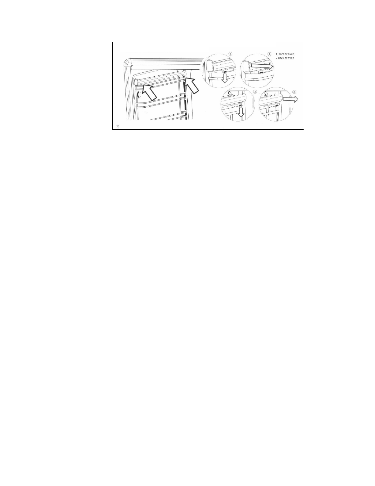
44
Removal of roof tray
The roof tray above the grill element can be removed for cleaning.
- Support the grill element with one hand while removing the 2 wing nuts that hold
the element in place.
- The element position will drop slightly allowing removal of the top liner.
- Once cleaned and dried, the top liner can be placed back into position, above
the element, and re-secured with the two wing nuts.
- The liner will only fit into one position so care must be taken to locate it on the
rear lugs and the front large lip must be facing downwards.
- Do not use the oven unless the liner is fitted and the element has been re-
secured with the wing
nuts.
Removal of the
soft
close drawer
- Pull the drawer forward. -
- Locate the grey clips behind the runners at the front of the drawer.
- Push in the clips and the drawer will release.
Replacing the
soft
close drawer
- Replace the drawer on to runners and close.
ACCESSORIES
Plinth kits
The three-sided plinth can be screwed to the underside of your cooker to conceal the
adjustable legs. The plinth is 9,3cm in height (cannot be used with extra high legs,
and is not suitable for 100X60 triple oven).
Griddle
Half flat, half ribbed griddle is perfect for searing meat, chicken and fish. Rests on pan
supports of all cookers.
Stay clean liners
These liners are easily fitted into the back and sides of all ovens (sides only in 30cm
and 40cm ovens). They are treated with a special material that absorbs grease
splashes during cooking. By heating the oven periodically to maximum temperature,
the splashes are burnt off to keep the oven interior like new..
Telescopic sliding shelves
Even when fully extended the telescopic system offers a safe and convenient way to
grill, baste and check food without removing the trays or dishes from the oven. One
set is included in the main oven of T version. Fits all ovens and works with the grill
tray and shelves.
Cast iron wok support
This accessory is placed over the pan support to use with round-bottomed woks and
balti pans
Extra high adjustable legs
These stainless steel legs increase the height of your cooker to accommodate kitchen
units 91cm - 94.5cm high. (not suitable for 100X60 triple oven)

45
TROUBLESHOOTING
The oven will not operate
- Is there power to the cooker?
- Is the automatic programmer set to manual?
- The main oven will not operate manually if the programmer is set to automatic
mode. (See page 32)
- Confirm that power is on by checking that the clock is functioning
- Check the switch fuse or circuit breaker.
The burners will not ignite
- Is there power to the cooker?
- Are the ignition candles or burner holes blocked? Are the burner rings and
burner caps seated firmly?
- Confirm that power IS on by checking that the clock is functioning.
- Check the switch fuse or circuit breaker.
- Check that the ignition candle is clean and the burner slots are dry and free of
debris.
- The burner rings should engage in the burner support. (See page 39)
The burner ignites but goes out when the knob is released
- The burners have flame failure devices fitted as
standard. Therefore, after
lighting the burner, keep the knob pressed in for 5-10 seconds to activate the
flame failure device.
The ignition candles are sparking continuously
- Is the hob wet from cleaning or a boil over?
- Turn off the
electricity
supply and thoroughly dry the burner components and
ignition candles.
The control knob are getting too hot
- Are you cooking with the oven door open?
- Keep the oven door shut when not in use or when grilling (the 100X60 triple oven
separate grill
compartment can be used for open door grilling for short periods only - max 15
min).
A control knob is loose on its shaft
- The knob retaining spring clip may have come out.
- Call our service and spares department for advice and a replacement if
necessary.
Food is cooking too quickly
- Are you using a fan function?
- Are you using the Fast preheat function?
- When using a fan function you should reduce the cooking temperature by 20°C
when compared to conventional cooking. Please see the cooking charts on
page 37 for temperatures.
‘Fast preheat’ is not suitable as a cooking function; it is only for pre-heating the oven.
Once the oven has reached temperature you should change over to your required
cooking function. Fast preheat should not be operated for long time.
Food is not cooking evenly
- Are you cooking large volumes of food or using large trays?
- Air needs to circulate through the oven for even cooking. Remove the grill pan
from the oven when not in use and always allow a gap on all four sides of dishes.
If cooking large quantities you may need to turn your trays during the cooking
time. Oversized baking sheets, roasting pans and cake tins will act as a baffle and
prevent hot air from travelling around the oven.
- Choose cooking equipment that allows a minimum of 2cm space on all sides to
allow the free movement of hot air.

46
The grill in the oven is slow
- Have you selected the correct function?
- Check that you have selected the grill function and not the top element. See
page 30.
The main oven takes a long time to preheat
- Have you tried using the Fast preheat function?
- Pre-heat with the Fast preheat function until the temperature has been reached,
then switch to your required cooking function.
- ‘Fast preheat’ should not be operated for long time.
- To order spare parts or accessories, please call our service & spares department.
The fan continues after the oven is turned off
- The cooling fan will run on and off intermittently for approximately 30 minutes
after the oven is switched off to keep the controls cool, this is normal.
Condensation forms in the oven
- Have you pre-heated the oven?
- Condensation is less likely to form when the oven or grill is pre-heated before
use.
Smoke is generated in the oven
- Have you selected the right cooking temperature?
- Are you cooking high fat content foods? Do you rarely use the grill?
- Have you cooked fatty foods under the grill? Does the oven interior, stay clean
liners or roof tray need to be cleaned?
- Remember to reduce the oven temperature by 20°C if using a fan function with
a recipe designed for conventional cooking.
- Use high sided dishes to contain fats and splashes.
- Clean the oven interior if necessary.
- Remember to remove and clean the grill pan after use.
- Leave the grill on far a few minutes after grilling or roasting to burn off fatty
deposits from the oven roof.
- Oven surfaces should be cleaned regularly to prevent build-up of cooking
residues. See page 41.
The door seal has
split
or perished
- Are you leaving the grill pan or foil at the bottom of the oven?
- Have you used caustic oven cleaners on or near the door seal?
- Always remove the grill pan when not in use as it can restrict airflow around the
oven.
- Caustic cleaners should not be used near the door seal area. Contact our
service & spares department for advice and a replacement seal if necessary
USEFUL TIPS
Cookshop thermometers
- These are often slow to react and they should only
be
used as a guide. You
should also keep in mind that oven temperatures can fluctuate between 10% and 15%
during any cooking period. This is normal on any oven and is caused by the elements
'cycling' on and off.
Correct cooking time
- In most
cases,
the cooking times stated in recipes should be used. However, the
cooking period should be reduced for dishes that require very long cooking time (such
as rich fruit cakes). As a guide, reduce the cooking time by 10 minutes for each hour
after the first hour of cooking, or after three quarters of the way through the cooking
period This also applies to very large joints of meat or turkey where a meat
thermometer
is
recommended. Always check that the food is hot and cooked before
serving.
Using foil
- Foil can be used to cover food in the oven but this should not come into close
proximity with the oven elements. Foil should not be used to line the oven cavity
or grill pan This can cause overheating, buckling and cracking of the enamel
surfaces.

47
- Silicon oven mats (sometimes used to reduce cleaning) must not be placed on
the floor of the oven when the base element
IS
in use (e.g. when using Bottom
Element only or Conventional Cooking. The silicon oven mats will damage the enamel
interior.
Doors and door seals
- The fit and general state of the oven doors and seals can affect temperatures in
the oven. Clean the oven seals regularly and check them for splits and tears Do not
leave oven cleaning materials in prolonged contact with the seals as this will shorten
their life span.
- Doors and their handles should not be used to move the cooker. This can pull
the door and its hinges out of
position
and cause heat loss or uneven heating of the
ovens.
Induction cookers
The induction hob uses a sophisticated zone management system which controls
the level of power available to each of the zones to prevent over loading of the
circuits and the power supply to the appliance.
The system automatically reduces the maximum power available to any one zone
when the other zones are being used at the same time at a high power setting If the
power level ls reduced on one zone. the power can be increased on other zones.
If several zones are used on maximum power at the same time, it is possible that
another zone may not operate. This can be managed by reducing the power level on
one of the other zones.
As an example. Using the front left and back left zones on level 9, would not allow the
middle zone to operate; this would register as an inactive zone with a line in the middle
of the display. Turning the back left zone down to level 8 would allow the middle zone
to operate up to level 7.
100x60 triple oven levelling feet
The cooker is equipped with 4 leveling feet that can be adjusted up or down using the
Allen key supplied through the centre of the toot.
To level the cooker
Start by adjusting the rear left foot to the height of the worktop (or the final required
height of the cooker) as this foot is not accessible from the front of the appliance.
Place the cooker in position. The other 3 legs are accessible from the front of the
appliance. Remove the front plinth and storage drawer to access the 3 adjustable
legs; use the Allen key tool through the middle of the leg to make the required
height and leveling adjustments.
ABNORMAL OPERATION
Any of the following are considered to be abnormal operation and may require servicing:
- Yellow tipping of the burner flame.
- Burners failing to remain alight.
- Sooting up of cooking utensils.
- Burners extinguished by cupboard doors.
- Burners not igniting properly.
- Gas valves, which are difficult to turn.
In case the appliance fails to operate correctly, contact Bertazzoni.
AFTER-SALES TECHNICAL SERVICE AND SPARE PARTS
TECHNICAL SERVICE AND SPARE PARTS
Before leaving the factory, this appliance was tested and adjusted by specialist skilled staff to give the best
operating results. Any subsequent necessary repairs or adjustments must be carried out with the greatest
care and attention by authorised personnel. For this reason, we strongly advise you contact the Bertazzoni
Service Centre, specifying the nature of the problem, the model of the equipment and the serial number. This
data is provided on the data label adhered to the base of the appliance and on the duplicate data label.
Always use original Bertazzoni spare parts.

48
ALL SERVICES MUST BE CARRIED OUT BY BERTAZZONI’S AUTHORISED PERSONNEL ONLY.
BERTAZZONI AUSTRALIA Pty Ltd
ABN 91 623 588 027
PO Box 5317 South Melbourne, Victoria 3205
Contact number 1800 65 42 65
Email: [email protected]
APPLY WIRING DIAGRAM LABELS