INSTRUCTION MANUAL
MANUAL DE INSTRUCCIONES
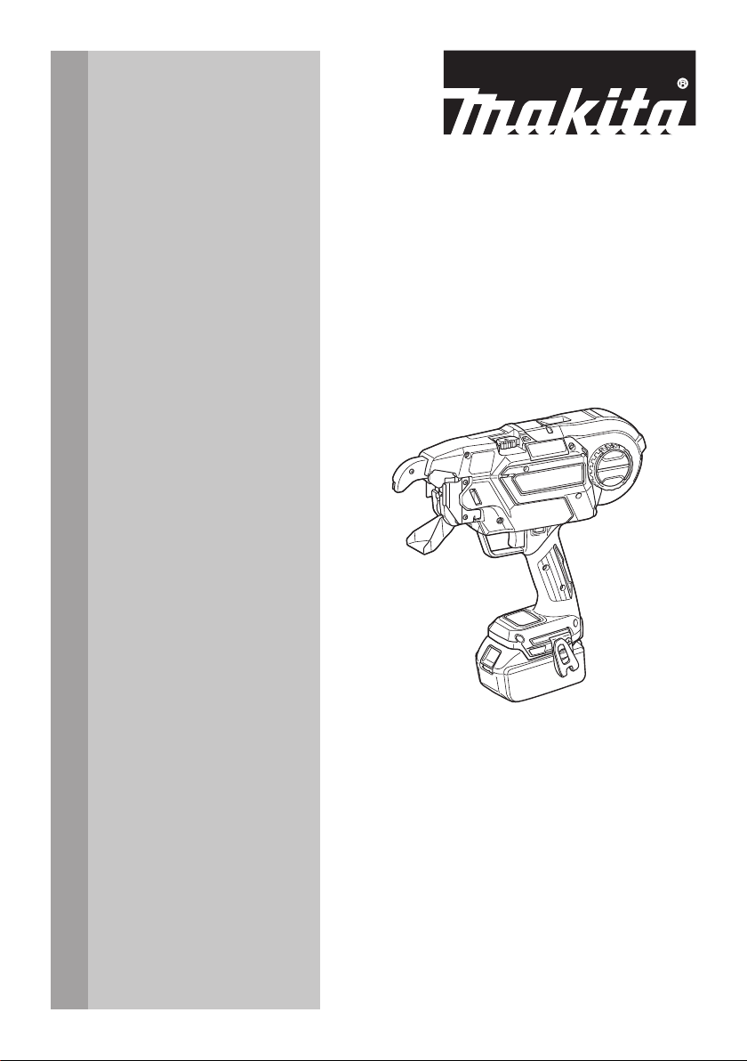
Cordless Rebar Tying Tool
Amarradora Inalámbrica de Varilla
XRT02
IMPORTANT: Read Before Using.
IMPORTANTE: Lea antes de usar.
2 ENGLISH
ENGLISH (Original instructions)
SPECIFICATIONS
Model: XRT02
Tie wire (Optional accessory) Annealing iron tie wire ø0.8 mm (21GA)
Poly coated tie wire ø0.9 mm (20GA)
Galvanized tie wire
*1
ø0.8 mm (21GA)
Approximate number of ties
per reel
Annealing iron tie wire Approximately 75 ties
Poly coated tie wire Approximately 65 ties
Galvanized tie wire
*1
Approximately 75 ties
Overall length 317 mm (12-1/2″)
Rated voltage D.C. 18 V
Net weight 2.4 - 2.7 kg (5.3 - 6.0 lbs)
*1
Available only when an optional wire guide B complete (EG) is installed in the arm.
• Due to our continuing program of research and development, the specications herein are subject to change
without notice.
• Specications and battery cartridge may dier from country to country.
• The weight may dier depending on the attachment(s), including the battery cartridge. The lightest and heavi-
est combinations, according to EPTA-Procedure 01/2014, are shown in the table.
Applicable battery cartridge and charger
Battery cartridge
BL1815N / BL1820B / BL1830 / BL1830B / BL1840B / BL1850B / BL1860B
Charger
DC18RC / DC18RD / DC18RE / DC18SD / DC18SE / DC18SF / DC18SH
• Some of the battery cartridges and chargers listed above may not be available depending on your region of
residence.
WARNING: Only use the battery cartridges and chargers listed above. Use of any other battery cartridges
and chargers may cause injury and/or re.
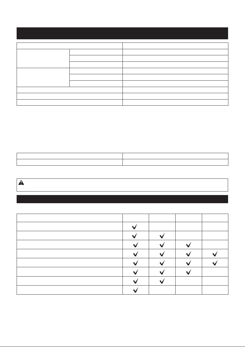
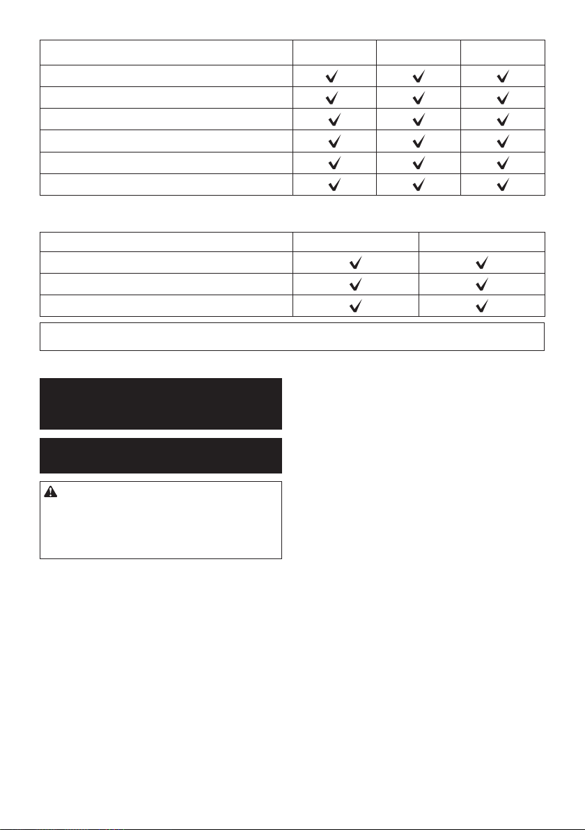
Combination of rebars that can be tied
Combination of 2 rebars
#4 (13 mm) #5 (16 mm) #6 (19 mm) #7 (22 mm)
#4 (13 mm)
*
- - -
#5 (16 mm)
*
- -
#6 (19 mm)
-
#7 (22 mm)
#8 (25 mm)
#9 (29 mm) -
#10 (32 mm)
- -
#11 (35 mm)
- - -
* The combination is not designed for high tying strength.
3 ENGLISH
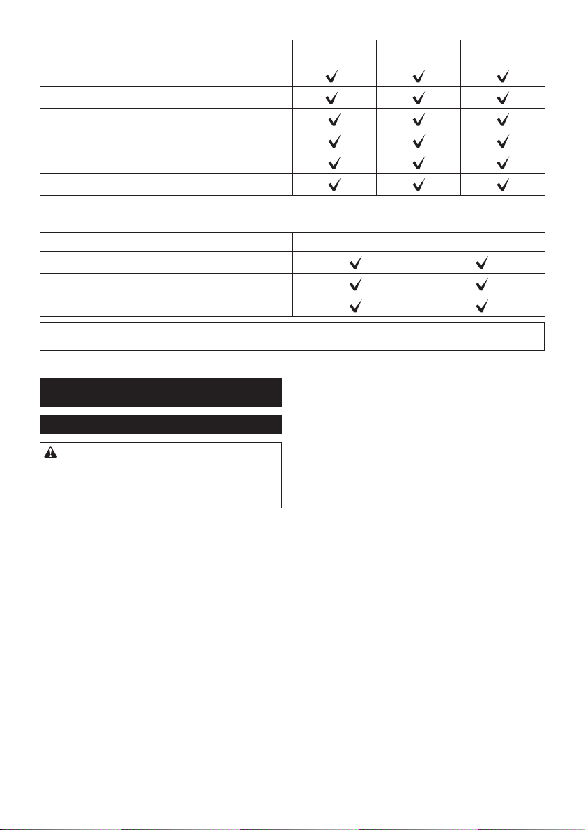
Combination of 3 rebars
#3 x #3
(10 mm x 10 mm)
#4 x #4
(13 mm x 13 mm)
#5 x #5
(16 mm x 16 mm)
#3 (10 mm)
*
#4 (13 mm)
*
#5 (16 mm)
#6 (19 mm)
#7 (22 mm)
#8 (25 mm)
* The combination is not designed for high tying strength.
Combination of 4 rebars
#3 x #3 (10 mm x 10 mm) #4 x #4 (13 mm x 13 mm)
#3 x #3 (10 mm x 10 mm)
#4 x #4 (13 mm x 13 mm)
#5 x #5 (16 mm x 16 mm)
NOTICE: If there is a gap between rebars or if the tool is used at an incorrect orientation, the rebars may not be
able to be tied.
SAFETY WARNINGS
General power tool safety warnings
WARNING: Read all safety warnings, instruc-
tions, illustrations and specications provided
with this power tool. Failure to follow all instructions
listed below may result in electric shock, re and/or
serious injury.
Save all warnings and instruc-
tions for future reference.
The term "power tool" in the warnings refers to your
mains-operated (corded) power tool or battery-operated
(cordless) power tool.
Work area safety
1. Keep work area clean and well lit. Cluttered or
dark areas invite accidents.
2. Do not operate power tools in explosive atmo-
spheres, such as in the presence of ammable
liquids, gases or dust. Power tools create sparks
which may ignite the dust or fumes.
3. Keep children and bystanders away while
operating a power tool. Distractions can cause
you to lose control.
Electrical Safety
1. Power tool plugs must match the outlet. Never
modify the plug in any way. Do not use any
adapter plugs with earthed (grounded) power
tools. Unmodied plugs and matching outlets will
reduce risk of electric shock.
2. Avoid body contact with earthed or grounded
surfaces, such as pipes, radiators, ranges and
refrigerators. There is an increased risk of elec-
tric shock if your body is earthed or grounded.
3. Do not expose power tools to rain or wet con-
ditions. Water entering a power tool will increase
the risk of electric shock.
4. Do not abuse the cord. Never use the cord for
carrying, pulling or unplugging the power tool.
Keep cord away from heat, oil, sharp edges
or moving parts. Damaged or entangled cords
increase the risk of electric shock.
5. When operating a power tool outdoors, use an
extension cord suitable for outdoor use. Use of
a cord suitable for outdoor use reduces the risk of
electric shock.
6. If operating a power tool in a damp location is
unavoidable, use a ground fault circuit inter-
rupter (GFCI) protected supply. Use of a GFCI
reduces the risk of electric shock.
7. Power tools can produce electromagnetic
elds (EMF) that are not harmful to the user.
However, users of pacemakers and other similar
medical devices should contact the maker of their
device and/or doctor for advice before operating
this power tool.
Personal Safety
1. Stay alert, watch what you are doing and use
common sense when operating a power tool.
Do not use a power tool while you are tired or
under the inuence of drugs, alcohol or med-
ication. A moment of inattention while operating
power tools may result in serious personal injury.

4 ENGLISH
2. Use personal protective equipment. Always
wear eye protection. Protective equipment such
as dust mask, non-skid safety shoes, hard hat, or
hearing protection used for appropriate conditions
will reduce personal injuries.
3. Prevent unintentional starting. Ensure the
switch is in the o-position before connecting
to power source and/or battery pack, picking
up or carrying the tool. Carrying power tools with
your nger on the switch or energising power tools
that have the switch on invites accidents.
4. Remove any adjusting key or wrench before
turning the power tool on. A wrench or a key left
attached to a rotating part of the power tool may
result in personal injury.
5. Do not overreach. Keep proper footing and
balance at all times. This enables better control
of the power tool in unexpected situations.
6. Dress properly. Do not wear loose clothing or
jewellery. Keep your hair, clothing and gloves
away from moving parts. Loose clothes, jewel-
lery or long hair can be caught in moving parts.
7. If devices are provided for the connection of
dust extraction and collection facilities, ensure
these are connected and properly used. Use of
dust collection can reduce dust-related hazards.
8.
Do not let familiarity gained from frequent use of
tools allow you to become complacent and ignore
tool safety principles. A careless action can cause
severe injury within a fraction of a second.
9. Always wear protective goggles to protect
your eyes from injury when using power tools.
The goggles must comply with ANSI Z87.1 in
the USA.
It is an employer's responsibility to enforce the
use of appropriate safety protective equipment
by the tool operators and by other persons in
the immediate working area.
Power tool use and care
1. Do not force the power tool. Use the correct
power tool for your application. The correct
power tool will do the job better and safer at the
rate for which it was designed.
2. Do not use the power tool if the switch does
not turn it on and o. Any power tool that cannot
be controlled with the switch is dangerous and
must be repaired.
3. Disconnect the plug from the power source
and/or remove the battery pack, if detachable,
from the power tool before making any adjust-
ments, changing accessories, or storing power
tools. Such preventive safety measures reduce
the risk of starting the power tool accidentally.
4. Store idle power tools out of the reach of chil-
dren and do not allow persons unfamiliar with
the power tool or these instructions to operate
the power tool. Power tools are dangerous in the
hands of untrained users.
5. Maintain power tools and accessories. Check
for misalignment or binding of moving parts,
breakage of parts and any other condition that
may aect the power tool’s operation. If dam-
aged, have the power tool repaired before use.
Many accidents are caused by poorly maintained
power tools.
6. Keep cutting tools sharp and clean. Properly
maintained cutting tools with sharp cutting edges
are less likely to bind and are easier to control.
7. Use the power tool, accessories and tool bits
etc. in accordance with these instructions, tak-
ing into account the working conditions and
the work to be performed. Use of the power tool
for operations dierent from those intended could
result in a hazardous situation.
8. Keep handles and grasping surfaces dry,
clean and free from oil and grease. Slippery
handles and grasping surfaces do not allow for
safe handling and control of the tool in unexpected
situations.
9. When using the tool, do not wear cloth work
gloves which may be entangled. The entangle-
ment of cloth work gloves in the moving parts may
result in personal injury.
Battery tool use and care
1. Recharge only with the charger specied by
the manufacturer. A charger that is suitable for
one type of battery pack may create a risk of re
when used with another battery pack.
2. Use power tools only with specically desig-
nated battery packs. Use of any other battery
packs may create a risk of injury and re.
3. When battery pack is not in use, keep it away
from other metal objects, like paper clips,
coins, keys, nails, screws or other small metal
objects, that can make a connection from one
terminal to another. Shorting the battery termi-
nals together may cause burns or a re.
4. Under abusive conditions, liquid may be
ejected from the battery; avoid contact. If con-
tact accidentally occurs, ush with water. If
liquid contacts eyes, additionally seek medical
help. Liquid ejected from the battery may cause
irritation or burns.
5. Do not use a battery pack or tool that is dam-
aged or modied. Damaged or modied batteries
may exhibit unpredictable behaviour resulting in
re, explosion or risk of injury.
6. Do not expose a battery pack or tool to re or
excessive temperature. Exposure to re or tem-
perature above 130 °C may cause explosion.
7. Follow all charging instructions and do not
charge the battery pack or tool outside the
temperature range specied in the instruc-
tions. Charging improperly or at temperatures
outside the specied range may damage the
battery and increase the risk of re.
Service
1. Have your power tool serviced by a qualied
repair person using only identical replacement
parts. This will ensure that the safety of the power
tool is maintained.
2. Never service damaged battery packs. Service
of battery packs should only be performed by the
manufacturer or authorized service providers.
3. Follow instruction for lubricating and chang-
ing accessories.
4. Do not modify or attempt to repair the appli-
ance or the battery pack except as indicated in
the instructions for use and care.

5 ENGLISH
Cordless rebar tying tool safety
warnings
1. Never point the tool toward a person. Never
put your hands or feet close to the tool tip.
If you accidentally operate the tool while it is
touching someone, it will lead to an unexpected
accident.
2. Do not load wire while the power to the tool is
turned on. Otherwise, you may get caught in the
wire and injured.
3. Do not use the tool without closing the reel
cover. Otherwise, the wire reel may come o and
cause an accident.
4. Be sure to check that the diameters of rebars
to be tied are within the tool capacity before
beginning work.
5. Wear clothes that have close-tting hemlines
and sleeves. Do not work with a towel or other
object wrapped around your neck. Otherwise,
they may get caught in the rotating part and cause
an accident.
6. Be sure to inspect the following points before
using the tool.
• Check that no parts are damaged
• Check that no bolts are loose
• Check that safety devices operate
normally
7. If any abnormalities are found, stop using the
tool immediately. Do not repair the tool by
yourself. Ask your local Makita Service Center
for repairs. If the tool is used in an incomplete
state, an accident may occur.
8. When installing the battery cartridge, be sure
to lock the trigger and do not place your nger
on the trigger. Incorrect operation may cause an
accident.
9. When tying rebars, exercise care not to move
them. If rebars move due to tying, you may be
injured.
10. Do not touch the wires during the wire tying
process. Otherwise, you may get caught in the
wire and injured.
11. Do not bring your hands close to the tying
point during the wire tying process. Otherwise,
you may get caught in the wire and injured.
12. Hold the grip of the tool rmly during the wire
tying process. Otherwise, your wrist may be
twisted or your body may be pulled, which may
result in an injury.
13. Do not move to the next tying point until the
current wire tying process is completed.
Otherwise, you may be injured.
14. Pay attention to the end of the wire during the
wire tying process. Otherwise, your hand may
be caught by the end of the wire, and you may be
injured.
15. Do not touch the contact plate during the wire
tying process. If you need to touch the contact
plate, be sure to lock the trigger, or turn the
power switch o and remove the battery car-
tridge. Otherwise, you may be injured.
16. When you have completed the wire tying pro-
cess, pull the tool up vertically. Otherwise, the
arm may be caught on rebars, which may cause
an accident.
17. Be careful not to drop, bump, or hit the tool.
If a strong impact is applied prior to the tool
being used, make sure that the tool is not dam-
aged or cracked, and that the safety devices
operate normally. Otherwise, an accident may
occur.
18. If any of the following phenomena occur, lock
the trigger, turn the power switch o, and
remove the battery cartridge from the tool.
If the tool operates incorrectly, an accident may
occur.
• If an operating sound is heard as soon as
the battery cartridge is mounted.
• If overheating or abnormal smells or
noises are detected.
• When you are taking measures in
response to the error display. (Ask your
local Makita Service Center for repairs.)
• When loading or unloading a wire reel.
• When you move while holding the tool
during work.
• When you do not use the tool.
• When you inspect or adjust the tool.
• When you remove a stranded wire.
19. When working on scaolding, always stabilize
it and work using a posture that will ensure
you maintain your balance. If scaolding is
unstable, an accident may occur.
20. When working on a roof or similar locations,
move in a forward direction while working so
that you can see where you are going. If you
move in a backward direction while working, you
may lose your footing and cause an accident.
21. If you are working in a highly elevated loca-
tion, ensure that no one is below you, and pay
attention to ensure you do not drop any tools
while working. Dropping the tool may cause an
accident.
22. Do not use the tool for any work other than
wire tying. Otherwise, an accident may occur.
23. Always use Makita's genuine wires. If wires are
not used for a long period of time, they may
rust. Do not use rusted wires. Otherwise, they
may cause an accident.
24. After tying, check for wire breakage due to
excessive twisting. If any wires are broken,
tying strength will be lost. Adjust the tying
strength, and tie the rebars again.
25. Securely place the arm against the rebars. If
it is not securely positioned, a clearance will be
created between the rebars, and tying strength will
be compromised.
6 ENGLISH
Symbols
The followings show the symbols used for tool.
volts
direct current
Keep hands away from the tool tip.
Important safety instructions for
battery cartridge
1.
Before using battery cartridge, read all instruc-
tions and cautionary markings on (1) battery
charger, (2) battery, and (3) product using battery.
2.
Do not disassemble or tamper with the battery car-
tridge. It may result in a re, excessive heat, or explosion.
3. If operating time has become excessively
shorter, stop operating immediately. It may
result in a risk of overheating, possible burns
and even an explosion.
4.
If electrolyte gets into your eyes, rinse them out
with clear water and seek medical attention right
away. It may result in loss of your eyesight.
5. Do not short the battery cartridge:
(1) Do not touch the terminals with any con-
ductive material.
(2) Avoid storing battery cartridge in a con-
tainer with other metal objects such as
nails, coins, etc.
(3) Do not expose battery cartridge to water
or rain.
A battery short can cause a large current ow, over-
heating, possible burns and even a breakdown.
6. Do not store and use the tool and battery car-
tridge in locations where the temperature may
reach or exceed 50 °C (122 °F).
7. Do not incinerate the battery cartridge even if
it is severely damaged or is completely worn
out. The battery cartridge can explode in a re.
8. Do not nail, cut, crush, throw, drop the battery
cartridge, or hit against a hard object to the
battery cartridge. Such conduct may result in a
re, excessive heat, or explosion.
9. Do not use a damaged battery.
10.
The contained lithium-ion batteries are subject to
the Dangerous Goods Legislation requirements.
For commercial transports e.g. by third parties,
forwarding agents, special requirement on pack-
aging and labeling must be observed.
For preparation of the item being shipped, consulting an
expert for hazardous material is required. Please also
observe possibly more detailed national regulations.
Tape or mask o open contacts and pack up the
battery in such a manner that it cannot move
around in the packaging.
11. When disposing the battery cartridge, remove
it from the tool and dispose of it in a safe
place. Follow your local regulations relating to
disposal of battery.
12. Use the batteries only with the products
specied by Makita. Installing the batteries to
non-compliant products may result in a re, exces-
sive heat, explosion, or leak of electrolyte.
13. If the tool is not used for a long period of time,
the battery must be removed from the tool.
14. During and after use, the battery cartridge may
take on heat which can cause burns or low
temperature burns. Pay attention to the han-
dling of hot battery cartridges.
15. Do not touch the terminal of the tool imme-
diately after use as it may get hot enough to
cause burns.
16. Do not allow chips, dust, or soil stuck into the
terminals, holes, and grooves of the battery
cartridge. It may cause heating, catching re,
burst and malfunction of the tool or battery car-
tridge, resulting in burns or personal injury.
17. Unless the tool supports the use near
high-voltage electrical power lines, do not use
the battery cartridge near high-voltage electri-
cal power lines. It may result in a malfunction or
breakdown of the tool or battery cartridge.
18. Keep the battery away from children.
SAVE THESE INSTRUCTIONS.
CAUTION: Only use genuine Makita batteries.
Use of non-genuine Makita batteries, or batteries that
have been altered, may result in the battery bursting
causing res, personal injury and damage. It will
also void the Makita warranty for the Makita tool and
charger.
Tips for maintaining maximum
battery life
1. Charge the battery cartridge before completely
discharged. Always stop tool operation and
charge the battery cartridge when you notice
less tool power.
2. Never recharge a fully charged battery car-
tridge. Overcharging shortens the battery
service life.
3. Charge the battery cartridge with room tem-
perature at 10 °C - 40 °C (50 °F - 104 °F). Let
a hot battery cartridge cool down before
charging it.
4. When not using the battery cartridge, remove
it from the tool or the charger.
5. Charge the battery cartridge if you do not use
it for a long period (more than six months).
7 ENGLISH
FUNCTIONAL
DESCRIPTION
CAUTION: Always be sure that the tool is
switched o and the battery cartridge is removed
before adjusting or checking function on the tool.
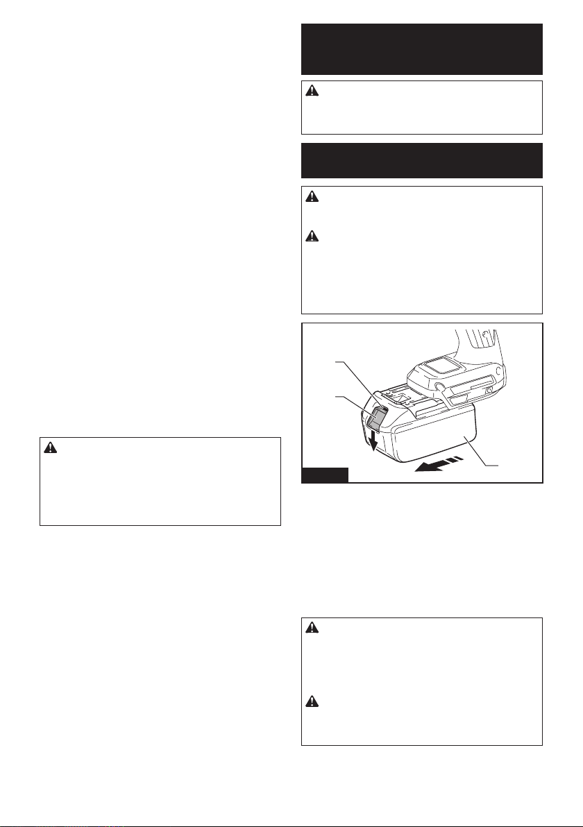
Installing or removing battery
cartridge
CAUTION: Always switch o the tool before
installing or removing of the battery cartridge.
CAUTION: Hold the tool and the battery car-
tridge rmly when installing or removing battery
cartridge. Failure to hold the tool and the battery
cartridge rmly may cause them to slip o your hands
and result in damage to the tool and battery cartridge
and a personal injury.
1
2
3
Fig.1
► 1. Red indicator 2. Button 3. Battery cartridge
To remove the battery cartridge, slide it from the tool
while sliding the button on the front of the cartridge.
To install the battery cartridge, align the tongue on the
battery cartridge with the groove in the housing and slip
it into place. Insert it all the way until it locks in place
with a little click. If you can see the red indicator as
shown in the gure, it is not locked completely.
CAUTION: Always install the battery cartridge
fully until the red indicator cannot be seen. If not,
it may accidentally fall out of the tool, causing injury to
you or someone around you.
CAUTION: Do not install the battery cartridge
forcibly. If the cartridge does not slide in easily, it is
not being inserted correctly.
Indicating the remaining battery capacity
Only for battery cartridges with the indicator
1
2
Fig.2
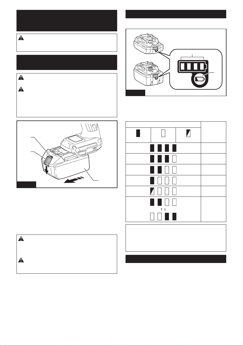
► 1. Indicator lamps 2. Check button
Press the check button on the battery cartridge to indi-
cate the remaining battery capacity. The indicator lamps
light up for a few seconds.
Indicator lamps Remaining
capacity
Lighted O Blinking
75% to 100%
50% to 75%
25% to 50%
0% to 25%
Charge the
battery.
The battery
may have
malfunctioned.
NOTE: Depending on the conditions of use and the
ambient temperature, the indication may dier slightly
from the actual capacity.
NOTE: The rst (far left) indicator lamp will blink when
the battery protection system works.
Tool / battery protection system
The tool is equipped with a tool/battery protection sys-
tem. This system automatically cuts o power to the
motor to extend tool and battery life. The tool will auto-
matically stop during operation if the tool or battery is
placed under one of the following conditions:
Overload protection
When the tool or battery is operated in a manner that
causes it to draw an abnormally high current, the tool
automatically stops and the corresponding error number
is displayed on the display panel. In this situation, turn
the tool o and stop the application that caused the tool
to become overloaded. Then turn the tool on to restart.
8 ENGLISH
Overheat protection
When the tool or battery is overheated, the tool stops
automatically and the corresponding error number is
displayed on the display panel. In this case, let the tool
and battery cool before turning the tool on again.
Overdischarge protection
When the battery capacity is not enough, the tool stops
automatically and the corresponding error number is
displayed on the display panel. In this case, remove the
battery from the tool and charge the battery.
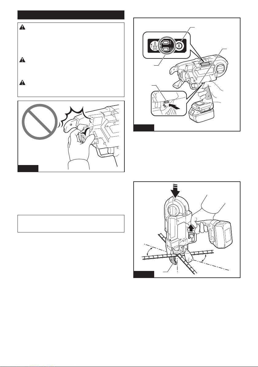
Main power switch
CAUTION: When you turn the power on, never
bring your limbs or face close to the binding or
rotating parts of the tool tip. Otherwise, you may
be injured.
CAUTION: When the power is turned on,
never touch the binding or rotating parts of the
tool tip. Otherwise, you may be injured.
CAUTION: Before inserting the battery car-
tridge, be sure to release your ngers from the
switch trigger and lock the trigger. If you insert
the battery cartridge while the switch trigger is being
pulled, it may cause an accident if the wire tying
process is accidentally carried out.
Fig.3
When you press the power button, the power turns
on and the tying mode lamp lights up. In order for the
tool to adjust its initial position, it operates temporarily.
When adjustment has completed, the tool stops auto-
matically. When you press the power button again, the
power turns o and the tying mode lamp goes out.
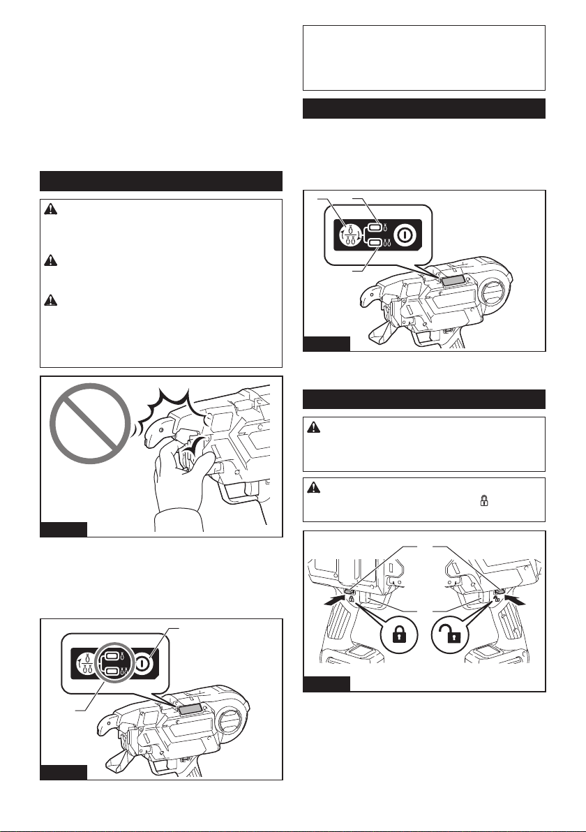
1
2
Fig.4
► 1. Tying mode lamp 2. Power button
NOTE: The tool has an auto power-o function. If the
switch trigger is not pulled for 10 minutes, the tool
is automatically turned o to reduce battery power
consumption.
NOTE: To restart the tool, turn the power on again.
Mode switching button
When the power is turned on and the tying mode lamp
is lit, you can select the single actuation mode or the
continuous actuation mode via the mode switching but-
ton. When you turn the power on again, the tool starts in
the mode that was most recently selected.
2
3
1
Fig.5
► 1. Mode switching button 2. Single actuation mode
3. Continuous actuation mode
Switch action
WARNING: Before installing the battery car-
tridge into the tool, always check to see that the
switch trigger actuates properly and returns to
the "OFF" position when released.
CAUTION: When not operating the tool,
depress the trigger-lock button from
side to
lock the switch trigger in the OFF position.
2
1
AB
Fig.6
► 1. Switch trigger 2. Trigger-lock button
To prevent the switch trigger from accidentally pulled,
the trigger-lock button is provided. To start the tool,
depress the trigger-lock button from A side and pull the
switch trigger. Release the switch trigger to stop. After
use, press in the trigger-lock button from B side.

9 ENGLISH
When you pull the switch trigger, the tool performs the next
sequential operations as follows, and the tool stops automatically.
1. Feed the wire.
2. Cut the wire.
3. The hook holds and twists the wire.
4. The hook returns to the original position.
Tying strength setting
CAUTION: Be sure to lock the trigger before
starting the adjustment. When you turn the power
on, never bring your limbs or face close to the
binding or rotating parts of the tool tip. Otherwise,
you may be injured.
Fig.7
You can set the tying strength by adjusting the tying strength
adjusting button. Tying strength is shown on the display panel.
2
1
Fig.8
► 1. Tying strength adjusting button 2. Display panel
If the wire is broken o, tying strength will be lost. After
tying, check the twisted portion for breakage.
If the wire is broken o, adjust the tying strength using the
tying strength adjusting button, and tie the rebars again.
Remaining battery notication
When the battery voltage drops below the required level,
the tool will stop operating, an error tone will sound, and
the number "4" will appear on the display panel. The error
tone will continue to sound until the power is turned o.
NOTE: If the ambient temperature is extremely low,
the error tone may sound even when the battery
contains sucient power.
ASSEMBLY
CAUTION: Always be sure that the tool is
switched o and the battery cartridge is removed
before carrying out any work on the tool.
Loading the tie wire (wire reel)
CAUTION: Before mounting or dismounting
tie wires and accessories, be sure to turn the
power o, lock the trigger, and remove the battery
cartridge. Failure to do so may cause an accident.
NOTICE: Using wires other than Makita's genu-
ine tie wires may cause the tool to malfunction.
1. Push the release lever, and lock it with the lock
lever.
1
2
Fig.9
► 1. Release lever 2. Lock lever
When you push the release lever, a gap is created
between the left and right feed gears.
1
2
3
Fig.10
► 1. Release lever 2. Lock lever 3. Feed gears

10 ENGLISH
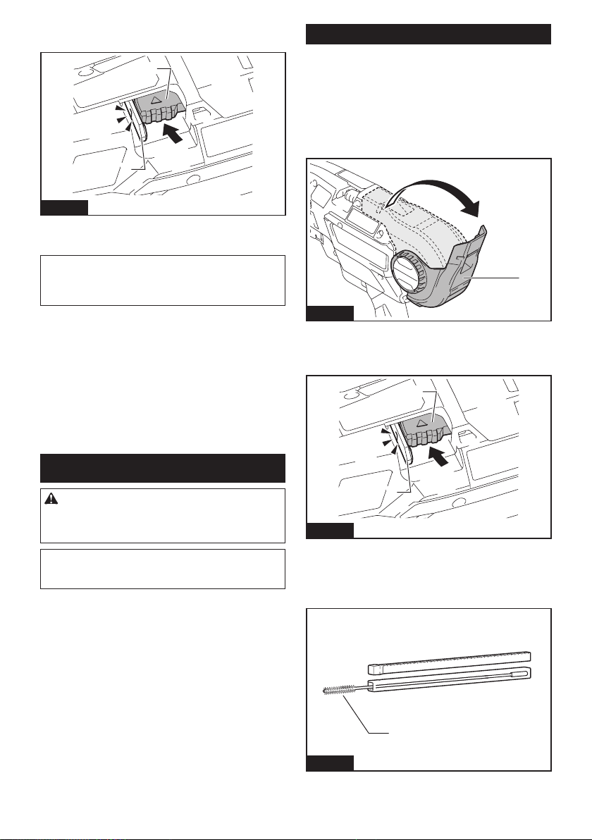
2. Open the reel cover.
1
Fig.11
► 1. Reel cover
3. Mount the wire reel on the tool in the orientation
shown in the gure.
1
Fig.12
► 1. Wire reel
NOTICE: Be sure to mount the wire reel in the
orientation shown in the gure. If it is mounted the
other way around, the wire will be released and may
be twisted.
4. Unhook the wire tip from the hook of reel.
1
Fig.13
► 1. Hook
5. Make the tip of the wire straight, and pass the wire
through the guide.
1
Fig.14
► 1. Guide
NOTE: If the tip of the wire is bent when it is passed
through the guide, the wire may become jammed in
the tool.
NOTE: If you force the wire when trying to pass it
through the guide, the wire may become jammed.
6. Pull the wire out approximately 10 mm from the tip
of the arm.
1
2
Fig.15
► 1. Arm 2. Approximately 10 mm
NOTICE: If the length of the pulled-out wire is
insucient, the wire may be broken o when tied,
or tying strength may be compromised due to
insucient wraps.

11 ENGLISH
7. Rewind the wire to eliminate its slack.
Fig.16
8. Release the lock lever. The release lever returns,
and the wire is held by the left and right gears.
2
1
Fig.17
► 1. Lock lever 2. Release lever
1
23
Fig.18
► 1. Gear 2. Path of the wire 3. Wire
NOTICE: When the lock lever is released and
when the left and right gears mesh with each
other, the grooves in the gears form a space. This
space becomes the path for the wire. Make sure
that the wire is passed through this path.
9. Close the reel cover.
1
Fig.19
► 1. Reel cover
12 ENGLISH
Replacing wire guide B
Optional accessory
The wire guide B (in silver color) in the arm can be
replaced with an optional wire guide B (EG) (in black
color) according to the type of tying wire to use.
Find the right combination in the following table. Then
replace the standard equipped wire guide B with an
optional wire guide B (EG) if necessary.
Standard
equipped wire
guide B complete
(silver)
Optional wire
guide B complete
(black)
Annealing iron tie wire
Poly coated tie wire -
Galvanized tie wire -
— : The combination is not valid.
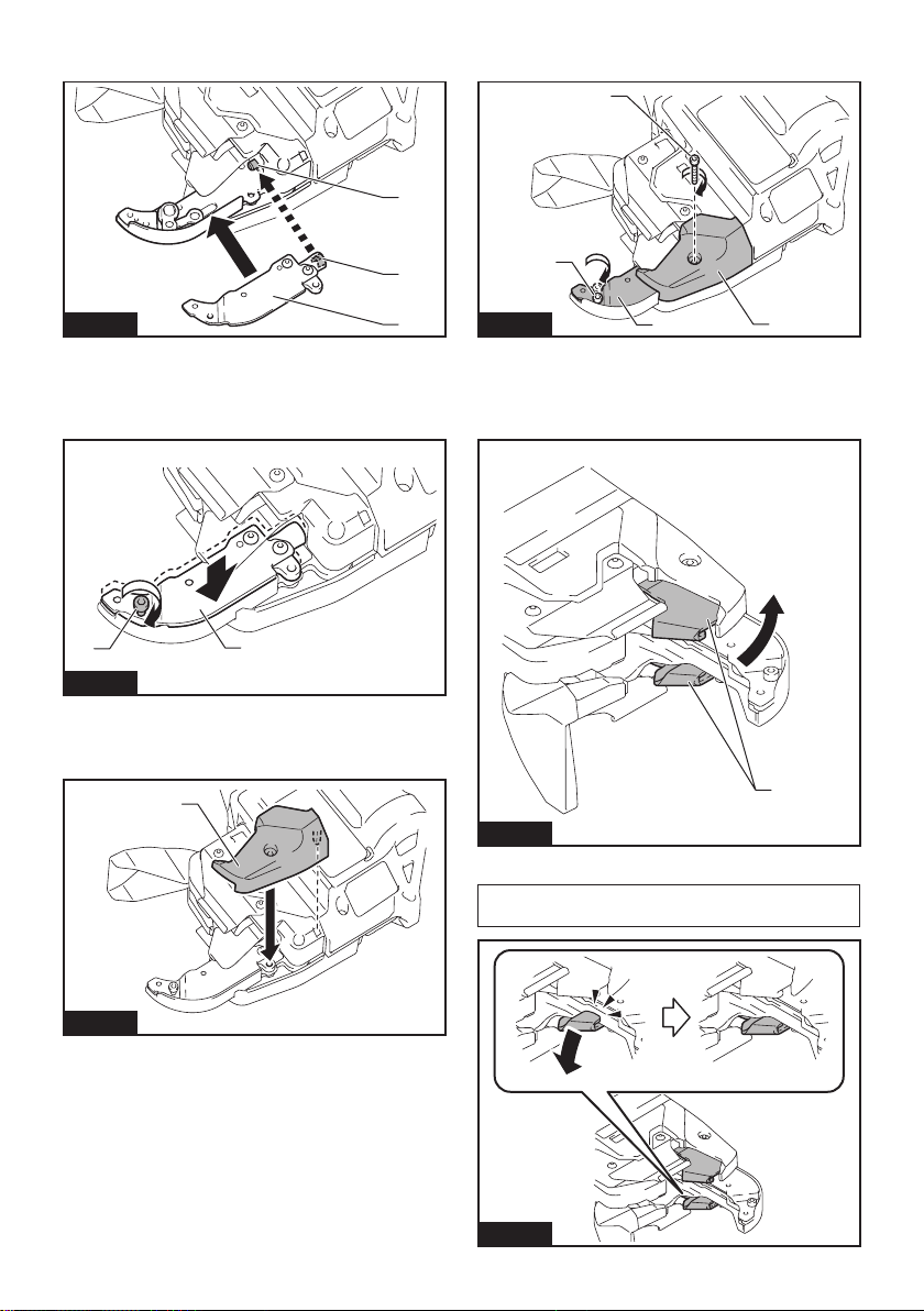
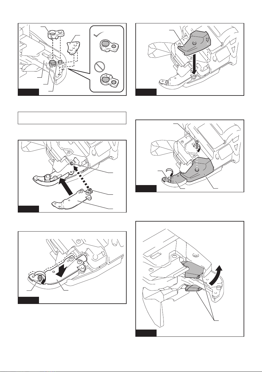
1. Loosen bolts A and B using the hex wrench
included in the tool package.
1
Fig.20
► 1. Hex wrench
1
2
3
4
Fig.21
► 1. Bolt A 2. Bolt B 3. Contact plate cover 4. Standard
equipped wire guide B (silver)
NOTICE: Do not forcibly remove any bolts that
cannot be removed using the hex wrench.
2.
Pull the contact plate cover up in the direction of the
arrow and remove it. Bolt B will be removed at the same time.
1
2
Fig.22
► 1. Contact plate cover 2. Bolt B
3. Remove bolt A, and remove the standard
equipped wire guide B (silver).
1
2
Fig.23
► 1. Bolt A 2. Standard equipped wire guide B (silver)
4.
Replace the standard equipped wire guide B (in silver
color) with an optional wire guide B (EG) (in black color).
1
Fig.24
► 1. Optional wire guide B (EG) (in black color).
13 ENGLISH
5. Align the pipe of the tool with the groove inside the
optional wire guide B (EG) (black), and assemble them.
1
2
3
Fig.25
► 1. Pipe 2. Groove 3. Optional wire guide B (EG)
(black).
6. Fix the optional wire guide B (EG) (black) by tem-
porarily tightening bolt A.
1
2
Fig.26
► 1. Bolt A 2. Optional wire guide B (EG) (black).
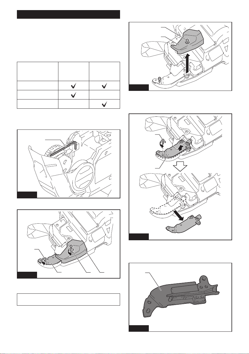
7. Install the contact plate cover in the direction of
the arrow.
1
Fig.27
► 1. Contact plate cover
8. Fix the optional wire guide B (EG) (black) and con-
tact plate cover securely by tightening bolt A and bolt B.
1
2
3
4
Fig.28
► 1. Optional wire guide B (EG) (black). 2. Contact
plate cover 3. Bolt A 4. Bolt B
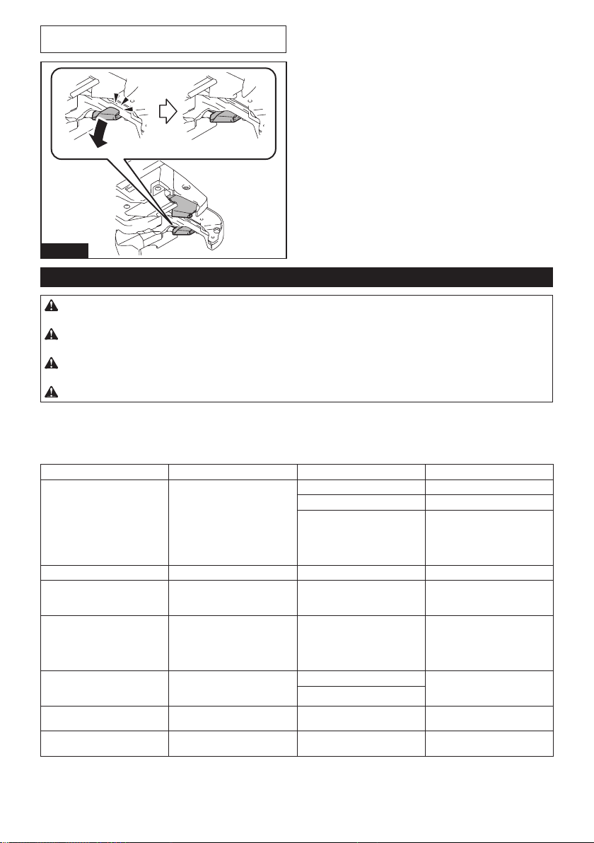
9. After assembling, conrm that the contact plate
can move as shown in the gure.
1
Fig.29
► 1. Contact plate
NOTE: If the contact plate is caught, press it as
shown in the gure.
Fig.30

14 ENGLISH
OPERATION
Checking before work
CAUTION: If the tool has a safety mecha-
nism-related problem, do not use it. If you continue
to use it, an accident may occur.
Before using the tool, make sure that the safety mecha-
nism operates normally. If the tool operates without the
safety mechanism operating, stop using the tool imme-
diately. Ask your local Makita Service Center for repairs.
Checking the trigger-lock
The tool has the trigger-lock to prevent the tool from
operating when you do not intend to use it. Lock the trig-
ger and conrm that the switch trigger cannot be pulled.
Checking the curl guide
To prevent the operator from touching the binding or
rotating parts of the tool tip by mistake, the tool will not
operate even if the switch trigger is pulled while the
curl guide is opened. When the operator releases their
nger from the switch trigger and closes the curl guide,
the tool can operate.
1
Fig.31
► 1. Curl guide
Checkout for curl guide open/close
detection
Remove the tie wire, check the tool operation according
to the following steps, and make sure that the tool does
not start if the curl guide is open.
1. Turn the power o, and leave the curl guide open.
2. Turn the power on.
If the tool will not operate and if the value "2" is shown
on the display panel, the state of the tool is normal. Turn
the power o, and close the curl guide.
If the tool operates and if no error is shown on the dis-
play panel, the state of the tool is abnormal. Stop using
the tool immediately, and ask your local Makita Service
Center for repairs.
CAUTION: If you open the curl guide and turn
the power on to check the interlock, hold the curl
guide as shown in the gure. Never bring your
limbs or face close to the binding or rotating parts
of the tool tip. Otherwise, you may be injured.
Fig.32
15 ENGLISH
Tying work
CAUTION: Before inserting the battery car-
tridge, be sure to release your ngers from the
switch trigger and lock the trigger. If you insert
the battery cartridge while the switch trigger is being
pulled, it may cause an accident if the wire tying
process is accidentally carried out.
CAUTION: When you turn the power on, never
bring your limbs or face close to the binding or
rotating parts of the tool tip. Otherwise, you may
be injured.
CAUTION: When the power is turned on,
never touch the binding or rotating parts of the
tool tip. Otherwise, you may be injured.
Fig.33
Preparation before work
1. Make sure that the battery cartridge is removed
and the trigger is locked.
2. Insert the battery cartridge into the tool, and turn
the power on. When you turn the power on, the wire is
cut automatically.
NOTICE: Make sure that the tying mode lamp
lights up when the power is turned on. If it does
not light up, recharge the battery.
3. Release the trigger lock.
1
2
3
4
Fig.34
► 1. Trigger-lock button 2. Switch trigger 3. Power
button 4. Tying mode lamp
Single actuation mode
1. Push the arm rmly against the tying point. Make
sure to place the tool vertically over the rebars and
press the arm on the tying point at a 45° angle against
the crossed rebars.
45°
45°
1
Fig.35
► 1. Arm
2. Pull the switch trigger once.
3. The wire is fed and cut automatically.
4. The hook holds and twists the wire, then returns to
the original position after the wires have been tied.
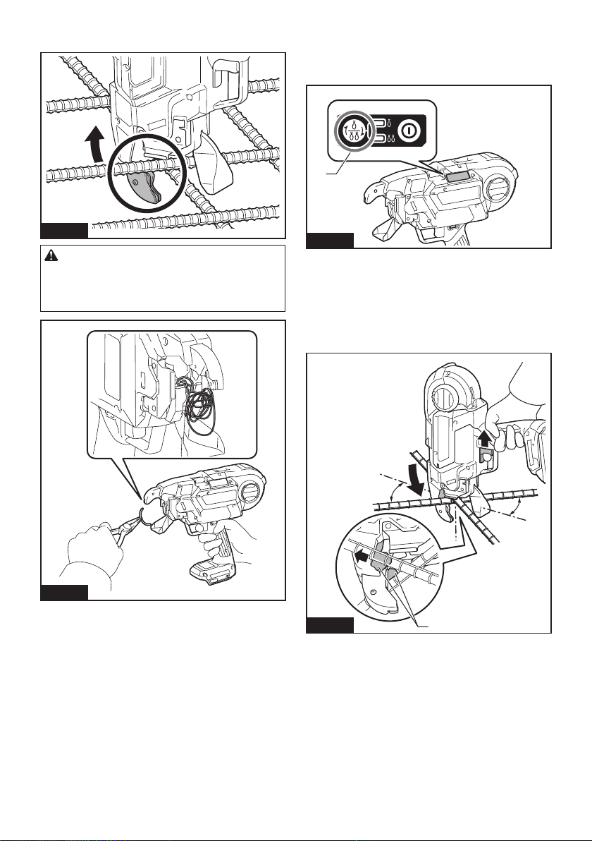
16 ENGLISH
5. After tying, be careful not to hook the arm on the
rebars, and then pull the tool up.
Fig.36
CAUTION: If the wire has clung to the binding
part of the tool tip, turn the power of the tool o.
Lock the trigger, remove the battery cartridge,
and remove the wire using tools such as nippers
or pliers.
Fig.37
Continuous actuation mode
1. Switch the tool mode from the single actuation
mode to the continuous actuation mode using the mode
switching button.
1
Fig.38
► 1. Mode switching button
2. Release the trigger lock.
3. While pulling the switch trigger, push the tool
vertically against the rebars, and press the arm against
the point where the rebars cross at a 45-degree angle.
Press the contact plate rmly against the tying point.
The wire will be tied.
45°
45°
1
Fig.39
► 1. Contact plate
17 ENGLISH
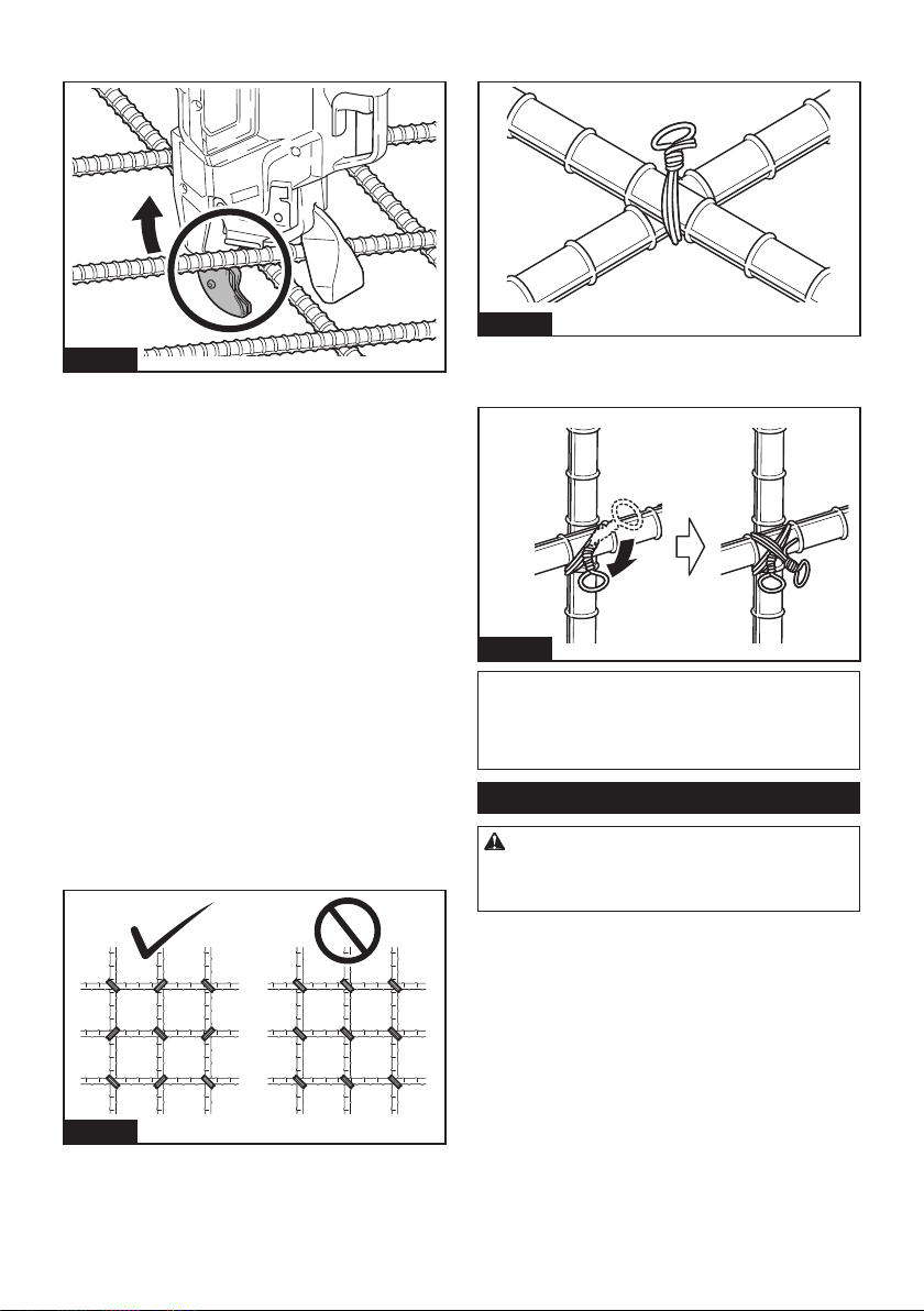
4. After tying, be careful not to hook the arm on the
rebars, and then pull the tool up.
Fig.40
Cautions on working
• If you move the arm from the tying position during
the wire tying process, the wire will get stuck on
the hook, which may lead to incorrect tying.
• Keep pressing the tool against the rebars until the
wire tying process is completed.
• Do not move to the next tying point until the cur-
rent wire tying process is completed.
• The tool tip rotating part (hook) twists the wire
during the wire tying process. Hold the grip rmly
so that your body is not pulled by the tool.
• Do not touch the wires during the wire tying
process.
• If you are repeating the wire tying processes in
the single actuation mode, fully release your nger
from the switch trigger. Then, continue to operate
the switch trigger.
• If you pull the switch trigger when there is no tie
wire left, an error is displayed. Replace with a new
tie wire and restart the tool.
Tying tips
• Tilt the tool at a 45° angle against the crossed
rebars, and tie the wire in alternate orientations as
shown in the gure.
Fig.41
• Tie the wire onto the at (with no unevenness)
sections of crossed rebars.
Fig.42
• If tying strength is insucient, change the tying
orientation and perform tying twice so that tying
strength increases.
Fig.43
NOTICE: When you make the second tie, bend
the tail of the rst tie before making the second
tie. Otherwise, the wire may be repelled a second
time. It may cling to the tool tip, and the hook may be
damaged.
Replacing the tie wires
CAUTION: When you replace the wire, be sure
to turn the power o, lock the trigger, and remove
the battery cartridge. Failure to do so may cause an
accident.
1. When wire has been used up, an error tone will
sound and error "1" will be displayed.
2. Lock the trigger, turn the power o, and remove
the battery cartridge.
18 ENGLISH
3. Push the release lever, and lock it with the lock
lever.
1
2
Fig.44
► 1. Release lever 2. Lock lever
4. Remove the wire reel from the tool.
NOTE: When wire has been used up normally,
approximately 20 cm of the wire remains wound on
the reel. In this state, replace the wire reel with a new
one.
If it is dicult to remove the wire reel from the tool,
follow the steps below.
1. Insert the battery cartridge into the tool, and
turn the power on. The tool feeds the wire and cuts it
automatically.
2. Lock the trigger, turn the power o, and remove
the battery cartridge.
3. Remove the wire breaks using tools such as nip-
pers or pliers.
MAINTENANCE
CAUTION: Always be sure that the tool is
switched o and the battery cartridge is removed
before attempting to perform inspection or
maintenance.
NOTICE: Never use gasoline, benzine, thinner,
alcohol or the like. Discoloration, deformation or
cracks may result.
To maintain product SAFETY and RELIABILITY,
repairs, any other maintenance or adjustment should
be performed by Makita Authorized or Factory Service
Centers, always using Makita replacement parts.
Cleaning the cutter section
When the tool is used, dust and wire particles may
become adhered to the cutter section. In such a case,
clean the cutter section according to the following pro-
cedure. The cleaning should be done each time you use
up a box of reel. (50 pcs.)
Using the wire brush
1. Open the reel cover.
1
Fig.45
► 1. Reel cover
2. Push the release lever, and lock it with the lock
lever.
1
2
Fig.46
► 1. Release lever 2. Lock lever
3. Pass the wire brush through the guide.
When inserting the wire brush, hold it short and push it
into the guide little by little.
1
Fig.47
► 1. Wire brush

19 ENGLISH
1
2
3
Fig.48
► 1. Gear 2. Guide 3. Wire brush
4. Push in the wire brush until its top end comes out
from the tip of the arm. And then pull out the wire brush.
This action is enough with one time.
1
2
Fig.49
► 1. Arm 2. Wire brush
5. Close the reel cover.
1
Fig.50
► 1. Reel cover
Using the air duster gun
Open the reel cover, push the release lever, and lock it
with the lock lever. Then bring the air duster gun close
to the guide and blow the air. Make sure the air comes
from the tip of the arm.
1
2
Fig.51
► 1. Air duster gun 2. Guide
Cleaning with disassembly
If the cutter section is clogged or a wire is caught in it,
disassemble the parts and clean them.
Disassembling and cleaning
1. Loosen bolts A and B using the hex wrench
included in the tool package.
1
Fig.52
► 1. Hex wrench

20 ENGLISH
1
2
3
4
Fig.53
►
1. Bolt A 2. Bolt B 3. Contact plate cover 4. Wire guide B
NOTICE: Do not forcibly remove any bolts that
cannot be removed using the hex wrench.
2.
Pull the contact plate cover up in the direction of the
arrow and remove it. Bolt B will be removed at the same time.
1
2
Fig.54
► 1. Contact plate cover 2. Bolt B
3. Remove bolt A, and remove wire guide B.
1
2
Fig.55
► 1. Bolt A 2. Wire guide B
4. Turn wire guide B over and clean its inside.
Fig.56
5. Remove top plate, cutter B, link arm A and cutter A
from arm plate A. Then, clean them.
1
2
3
4
5
Fig.57
► 1. Top plate 2. Cutter B 3. Link arm A 4. Cutter A
5. Arm plate A
Assembling
When cleaning is nished, assemble the parts accord-
ing to the following procedure.
1. Install cutter A and link arm A to t the shape of
arm plate A.
1
2
3
Fig.58
► 1. Cutter A 2. Link arm A 3. Arm plate A
21 ENGLISH
2. Install cutter B and the top plate onto arm plate A.
(Install cutter B on cutter A and link arm A.)
1
2
4
3
5
Fig.59
► 1. Cutter B 2. Top plate 3. Arm plate A 4. Cutter A
5. Link arm A
NOTICE: Face the projection of cutter B down-
ward, and install the cutter as shown in the gure.
3. Align the pipe of the tool with the groove inside the
wire guide B, and assemble them.
1
2
3
Fig.60
► 1. Pipe 2. Groove 3. Wire guide B
4. Fix wire guide B by temporarily tightening bolt A.
1
2
Fig.61
► 1. Bolt A 2. Wire guide B
5. Install the contact plate cover in the direction of
the arrow.
1
Fig.62
► 1. Contact plate cover
6. Fix wire guide B and contact plate cover securely
by tightening bolt A and bolt B.
1
2
3
4
Fig.63
► 1. Wire guide B 2. Contact plate cover 3. Bolt A
4. Bolt B
7. After assembling, conrm that the contact plate
can move as shown in the gure.
1
Fig.64
► 1. Contact plate
22 ENGLISH
NOTE: If the contact plate is caught, press it as
shown in the gure.
Fig.65
Error display and error tone
CAUTION: During inspection, be sure to lock the trigger, turn the power o, and remove the battery
cartridge. Failure to do so may cause an accident.
CAUTION: When you turn the power on, never bring your limbs or face close to the binding or rotating
parts of the tool tip. Otherwise, you may be injured.
CAUTION: When the power is turned on, never touch the binding or rotating parts of the tool tip.
Otherwise, you may be injured.
CAUTION: If an error tone sounds, or if the tool malfunctions, immediately stop using the tool.
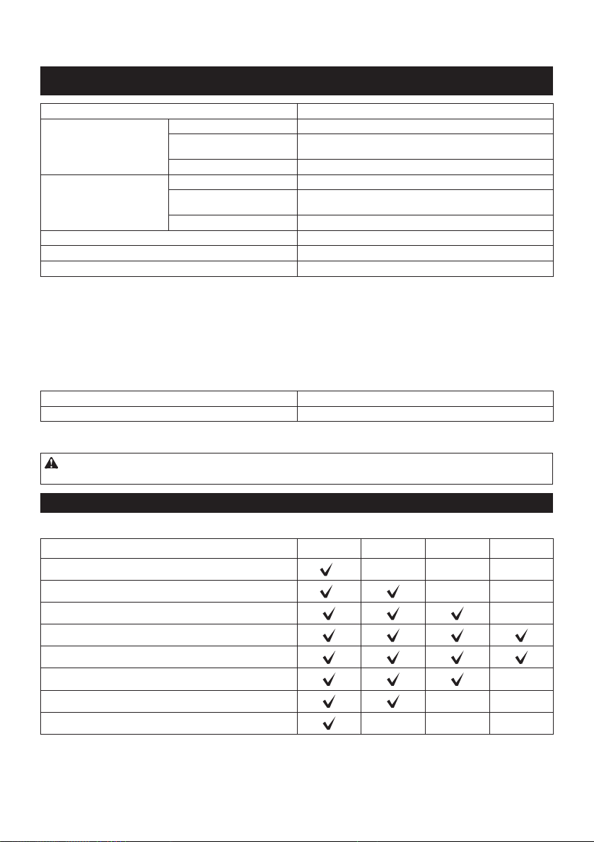
Error tone and display
If an error occurs, an error tone will sound, and an error number will be shown on the display panel. Refer to the
following table and take appropriate actions. If the error persists, ask Makita Authorized Service Centers for repairs.
Display Symptom Possible cause Solution
1 The tool stops operating. The wire has been used up. Load new tie wire.
Tie wire is not loaded. Load tie wire.
Wire feeding has failed. Check the orientation of the
tie wire.
Unload the tie wire, and load
it again.
Clean the path of wire.
2 The tool stops operating. The curl guide is open. Close the curl guide.
3 The tool does not perform the
tying process in continuous
actuation mode.
The contact plate is caught. Release the contact plate from
being caught.
4 The tool does not start.
The tool stops operating.
The battery has been
discharged.
The temperature of the battery
cartridge is abnormally high.
Recharge the battery.
Cool the battery cartridge
down.
Replace the battery cartridge
with a recharged one.
5 The tool stops operating. The motor is overloaded. Determine the cause of the
obstruction of the motor rotation
and solve the problem.
Motor failure
6 The tool stops operating. The temperature of the tool is
abnormally high.
Cool the tool down.
7 The tool does not start.
The tool stops operating.
Tool failure Ask Makita Authorized Service
Centers for repairs.

23
OPTIONAL
ACCESSORIES
CAUTION: These accessories or attachments
are recommended for use with your Makita tool
specied in this manual. The use of any other
accessories or attachments might present a risk of
injury to persons. Only use accessory or attachment
for its stated purpose.
If you need any assistance for more details regard-
ing these accessories, ask your local Makita Service
Center.
• Tie wire
• Wire guide B complete (EG)
• Wire brush
• Extension handle
• Makita genuine battery and charger
NOTE: Some items in the list may be included in the
tool package as standard accessories. They may
dier from country to country.
MAKITA LIMITED WARRANTY
Please refer to the annexed warranty sheet for the
most current warranty terms applicable to this product.
If annexed warranty sheet is not available, refer to the
warranty details set forth at below website for your
respective country.
United States of America: www.makitatools.com
Canada: www.makita.ca
Other countries: www.makita.com
ENGLISH
24 ESPAÑOL
ESPAÑOL (Instrucciones originales)
ESPECIFICACIONES
Modelo: XRT02
Alambre de amarre
(accesorio opcional)
Alambre de amarre de hierro recocido
ø0,8 mm (21GA)
Alambre de amarre recubierto
con resina de poliéster
ø0,9 mm (20GA)
Alambre de amarre galvanizado
*1
ø0,8 mm (21GA)
Número aproximado de ama-
rres por carrete
Alambre de amarre de hierro recocido
Aproximadamente 75 amarres
Alambre de amarre recubierto
con resina de poliéster
Aproximadamente 65 amarres
Alambre de amarre galvanizado
*1
Aproximadamente 75 amarres
Longitud total 317 mm (12-1/2″)
Tensión nominal 18 V c.c.
Peso neto 2,4 kg - 2,7 kg (5,3 lbs - 6,0 lbs)
*1
Disponible solo cuando se instala una guía de alambre B completa (EG) opcional en el brazo de la herramienta.
• Debido a nuestro continuo programa de investigación y desarrollo, las especicaciones aquí incluidas están
sujetas a cambio sin previo aviso.
• Las especicaciones y el cartucho de batería pueden variar de país a país.
• El peso puede variar en función de los accesorios, incluido el cartucho de batería. En la tabla se muestra la
combinación de peso más ligero y más pesado conforme al procedimiento 01/2014 de EPTA.
Cartucho de batería y cargador aplicables
Cartucho de batería
BL1815N / BL1820B / BL1830 / BL1830B / BL1840B / BL1850B / BL1860B
Cargador
DC18RC / DC18RD / DC18RE / DC18SD / DC18SE / DC18SF / DC18SH
• Algunos de los cartuchos de batería y cargadores enumerados arriba podrían no estar disponibles depen-
diendo de su área de residencia.
ADVERTENCIA: Use únicamente los cartuchos de batería y los cargadores indicados arriba. El uso de
cualquier otro cartucho de batería y cargador podría ocasionar una lesión y/o un incendio.
Combinación de varillas que pueden amarrarse
Combinación de 2 varillas
#4 (13 mm) #5 (16 mm) #6 (19 mm) #7 (22 mm)
#4 (13 mm)
*
- - -
#5 (16 mm)
*
- -
#6 (19 mm)
-
#7 (22 mm)
#8 (25 mm)
#9 (29 mm) -
#10 (32 mm)
- -
#11 (35 mm)
- - -
* La combinación no está diseñada para una fuerza de amarre elevada.
25 ESPAÑOL
Combinación de 3 varillas
#3 x #3
(10 mm x 10 mm)
#4 x #4
(13 mm x 13 mm)
#5 x #5
(16 mm x 16 mm)
#3 (10 mm)
*
#4 (13 mm)
*
#5 (16 mm)
#6 (19 mm)
#7 (22 mm)
#8 (25 mm)
* La combinación no está diseñada para una fuerza de amarre elevada.
Combinación de 4 varillas
#3 x #3 (10 mm x 10 mm) #4 x #4 (13 mm x 13 mm)
#3 x #3 (10 mm x 10 mm)
#4 x #4 (13 mm x 13 mm)
#5 x #5 (16 mm x 16 mm)
AVISO: Si hay un espacio entre las varillas o si la herramienta se utiliza en una orientación incorrecta, es posible
que las varillas no puedan amarrarse.
ADVERTENCIAS DE
SEGURIDAD
Advertencias generales de seguridad
para herramientas eléctricas
ADVERTENCIA: Lea todas las advertencias
de seguridad, instrucciones, ilustraciones y espe-
cicaciones suministradas con esta herramienta
eléctrica. El no seguir todas las instrucciones indi-
cadas a continuación podría ocasionar una descarga
eléctrica, incendio y/o lesiones graves.
Conserve todas las advertencias
e instrucciones como referencia
en el futuro.
En las advertencias, el término “herramienta eléctrica”
se reere a su herramienta eléctrica de funcionamiento
con conexión a la red eléctrica (con cableado eléctrico)
o herramienta eléctrica de funcionamiento a batería
(inalámbrica).
Seguridad en el área de trabajo
1. Mantenga el área de trabajo limpia y bien ilu-
minada. Las áreas oscuras o desordenadas son
propensas a accidentes.
2. No utilice las herramientas eléctricas en
atmósferas explosivas, tal como en la presen-
cia de líquidos, gases o polvo inamables. Las
herramientas eléctricas crean chispas que pueden
prender fuego al polvo o los humos.
3. Mantenga a los niños y curiosos alejados
mientras utiliza una herramienta eléctrica. Las
distracciones le pueden hacer perder el control.
Seguridad eléctrica
1. Las clavijas de conexión de las herramientas
eléctricas deberán encajar perfectamente en la
toma de corriente. No modique nunca la cla-
vija de conexión de ninguna forma. No utilice
ninguna clavija adaptadora con herramientas
eléctricas que tengan conexión a tierra (puesta
a tierra). La utilización de clavijas no modica-
das y que encajen perfectamente en la toma de
corriente reducirá el riesgo de que se produzca
una descarga eléctrica.
2.
Evite tocar con el cuerpo supercies conectadas
a tierra o puestas a tierra tales como tubos, radia-
dores, cocinas y refrigeradores. Si su cuerpo es
puesto a tierra o conectado a tierra existirá un mayor
riesgo de que sufra una descarga eléctrica.
3. No exponga las herramientas eléctricas a la
lluvia ni a condiciones húmedas. La entrada de
agua en una herramienta eléctrica aumentará el
riesgo de que se produzca una descarga eléctrica.
4. No maltrate el cable. Nunca utilice el cable
para transportar, jalar o desconectar la herra-
mienta eléctrica. Mantenga el cable alejado del
calor, aceite, objetos cortantes o piezas móvi-
les. Los cables dañados o enredados aumentan
el riesgo de sufrir una descarga eléctrica.
5. Cuando utilice una herramienta eléctrica en
exteriores, utilice un cable de extensión apro-
piado para uso en exteriores. La utilización de
un cable apropiado para uso en exteriores redu-
cirá el riesgo de que se produzca una descarga
eléctrica.

26 ESPAÑOL
6. Si no es posible evitar usar una herramienta
eléctrica en condiciones húmedas, utilice un
alimentador protegido con interruptor de cir-
cuito de falla a tierra (ICFT). El uso de un ICFT
reduce el riesgo de descarga eléctrica.
7. Las herramientas eléctricas pueden producir
campos electromagnéticos (CEM) que no son
dañinos para el usuario. Sin embargo, si los
usuarios tienen marcapasos y otros dispositivos
médicos similares, deberán consultar al fabricante
de su dispositivo y/o a su médico antes de operar
esta herramienta eléctrica.
Seguridad personal
1. Manténgase alerta, preste atención a lo que
está haciendo y utilice su sentido común
cuando opere una herramienta eléctrica. No
utilice una herramienta eléctrica cuando esté
cansado o bajo la inuencia de drogas, alco-
hol o medicamentos. Un momento de distracción
mientras opera las herramientas eléctricas puede
terminar en una lesión grave.
2. Use equipo de protección personal. Póngase
siempre protección para los ojos. El equipo
protector tal como máscara contra el polvo, zapa-
tos de seguridad antiderrapantes, casco rígido y
protección para oídos utilizado en las condiciones
apropiadas reducirá el riesgo de lesiones.
3. Impida el encendido accidental. Asegúrese
de que el interruptor esté en la posición de
apagado antes de conectar a la alimentación
eléctrica y/o de colocar el cartucho de batería,
así como al levantar o cargar la herramienta.
Cargar las herramientas eléctricas con su dedo
en el interruptor o enchufarlas con el interrup-
tor encendido hace que los accidentes sean
comunes.
4. Retire cualquier llave de ajuste o llave de
apriete antes de encender la herramienta. Una
llave de ajuste o llave de apriete que haya sido
dejada puesta en una parte giratoria de la herra-
mienta eléctrica puede ocasionar alguna lesión.
5. No utilice la herramienta donde no alcance.
Mantenga los pies sobre suelo rme y el equi-
librio en todo momento. Esto permite un mejor
control de la herramienta eléctrica en situaciones
inesperadas.
6. Use una vestimenta apropiada. No use ropa
suelta ni alhajas. Mantenga el cabello, la ropa
y los guantes alejados de las piezas móviles.
Las prendas de vestir holgadas, las alhajas y
el cabello largo suelto podrían engancharse en
estas piezas móviles.
7. Si dispone de dispositivos para la conexión
de equipos de extracción y recolección de
polvo, asegúrese de conectarlos y utilizarlos
debidamente. Hacer uso de la recolección de
polvo puede reducir los riesgos relacionados con
el polvo.
8. No permita que la familiaridad adquirida
debido al uso frecuente de las herramientas
haga que se sienta conado e ignore los prin-
cipios de seguridad de las herramientas. Un
descuido podría ocasionar una lesión grave en
una fracción de segundo.
9. Utilice siempre gafas protectoras para prote-
ger sus ojos de lesiones al usar herramientas
eléctricas. Las gafas deben cumplir con la
Norma ANSI Z87.1 en EUA.
Es responsabilidad del empleador imponer
el uso de equipos protectores de seguridad
apropiados a los operadores de la herramienta
y demás personas cerca del área de trabajo.
Mantenimiento y uso de la herramienta eléctrica
1. No fuerce la herramienta eléctrica. Utilice la
herramienta eléctrica correcta para su aplica-
ción. La herramienta eléctrica adecuada hará un
mejor trabajo y de forma más segura a la veloci-
dad para la que ha sido fabricada.
2. No utilice la herramienta eléctrica si el inte-
rruptor no la enciende y apaga. Cualquier
herramienta eléctrica que no pueda ser contro-
lada con el interruptor es peligrosa y debe ser
reemplazada.
3. Desconecte la clavija de la fuente de alimen-
tación y/o retire la batería de la herramienta
eléctrica, en caso de ser removible, antes de
realizar ajustes, cambiar accesorios o almace-
nar las herramientas eléctricas. Tales medidas
de seguridad preventivas reducirán el riesgo
de poner en marcha la herramienta eléctrica de
forma accidental.
4. Guarde la herramienta eléctrica que no use
fuera del alcance de los niños y no permita
que las personas que no están familiarizadas
con ella o con las instrucciones la operen. Las
herramientas eléctricas son peligrosas en manos
de personas que no saben operarlas.
5. Dé mantenimiento a las herramientas eléctri-
cas y los accesorios. Compruebe que no haya
piezas móviles desalineadas o estancadas,
piezas rotas y cualquier otra condición que
pueda afectar al funcionamiento de la herra-
mienta eléctrica. Si la herramienta eléctrica
está dañada, haga que la reparen antes de
utilizarla. Muchos de los accidentes son ocasio-
nados por no dar un mantenimiento adecuado a
las herramientas eléctricas.
6. Mantenga las herramientas de corte limpias
y losas. Si recibe un mantenimiento adecuado
y tiene los bordes alados, es probable que la
herramienta se atasque menos y sea más fácil
controlarla.
7.
Utilice la herramienta eléctrica, los accesorios y
las brocas de acuerdo con estas instrucciones,
considerando las condiciones laborales y el
trabajo a realizar. Si utiliza la herramienta eléctrica
para realizar operaciones distintas de las indicadas,
podrá presentarse una situación peligrosa.
8. Mantenga los mangos y supercies de asi-
miento secos, limpios y libres de aceite o
grasa. Los mangos y supercies de asimiento
resbalosos no permiten una manipulación segura
ni el control de la herramienta en situaciones
inesperadas.
9. Cuando vaya a utilizar esta herramienta, evite
usar guantes de trabajo de tela ya que éstos
podrían atorarse. Si los guantes de trabajo de
tela llegaran a atorarse en las piezas móviles,
esto podría ocasionar lesiones personales.

27 ESPAÑOL
Uso y cuidado de la herramienta a batería
1. Recargue sólo con el cargador especicado
por el fabricante. Un cargador que es adecuado
para un solo tipo de batería puede generar riesgo
de incendio al ser utilizado con otra batería.
2. Utilice las herramientas eléctricas solamente
con las baterías designadas especícamente
para ellas. La utilización de cualquier otra batería
puede crear un riesgo de lesiones o incendio.
3.
Cuando no se esté usando la batería, manténgala
alejada de otros objetos metálicos, como sujetapa-
peles (clips), monedas, llaves, clavos, tornillos u
otros objetos pequeños de metal los cuales pueden
actuar creando una conexión entre las terminales
de la batería. Originar un cortocircuito en las terminales
puede causar quemaduras o incendios.
4. En condiciones abusivas, podrá escapar
líquido de la batería; evite tocarlo. Si lo toca
accidentalmente, enjuague con agua. Si hay
contacto del líquido con los ojos, busque asis-
tencia médica. Puede que el líquido expulsado
de la batería cause irritación o quemaduras.
5. No utilice una herramienta ni una batería que
estén dañadas o hayan sido modicadas. Las
baterías dañadas o modicadas podrían oca-
sionar una situación inesperada provocando un
incendio, explosión o riesgo de lesiones.
6. No exponga la herramienta ni la batería al
fuego ni a una temperatura excesiva. La expo-
sición al fuego o a una temperatura superior a los
130 °C podría causar una explosión.
7.
Siga todas las instrucciones para la carga y evite cargar
la herramienta o la batería fuera del rango de tempera-
tura especicado en las instrucciones. Una carga inade-
cuada o a una temperatura fuera del rango especicado
podría dañar la batería e incrementar el riesgo de incendio.
Servicio
1. Haga que una persona calicada repare la
herramienta eléctrica utilizando sólo piezas de
repuesto idénticas. Esto asegura que se man-
tenga la seguridad de la herramienta eléctrica.
2.
Nunca dé servicio a baterías que estén dañadas. El
servicio a las baterías solamente deberá ser efectuado
por el fabricante o un agente de servicio autorizado.
3. Siga las instrucciones para la lubricación y
cambio de accesorios.
4. No modique ni intente reparar el aparato ni el
paquete de baterías salvo como se indique en
las instrucciones para el uso y cuidado.
Advertencias de seguridad para la
amarradora inalámbrica de varilla
1.
Nunca apunte la herramienta hacia una persona.
Nunca coloque las manos o los pies cerca de
la punta de la herramienta. Si la herramienta se
acciona involuntariamente mientras está en contacto
con una persona, ocurrirá un accidente.
2. No hay que cargar alambre cuando la herra-
mienta esté encendida. De lo contrario, podría
enredarse con el alambre y sufrir una lesión.
3. No utilice la herramienta sin cerrar la cubierta
del carrete. De lo contrario, el carrete de alambre
podría soltarse y causar un accidente.
4. Antes de empezar el trabajo, asegúrese de que
los diámetros de las varillas que desea ama-
rrar están dentro de los límites especicados
de la herramienta.
5. Use ropa con mangas y bajos ajustados. No
trabaje con una toalla o alguna otra prenda
colocada alrededor del cuello. De lo contrario,
podrían dar lugar a un accidente si se enganchan
con la pieza giratoria.
6. Asegúrese de inspeccionar los siguientes
elementos antes de usar la herramienta.
• Verique que no haya piezas dañadas
• Verique que no haya pernos sueltos
• Verique que los dispositivos de seguri-
dad funcionan normalmente
7. Si detecta anomalías, deje de usar la herra-
mienta inmediatamente. No intente reparar la
herramienta por su cuenta. Solicite la repara-
ción en el centro de servicio Makita de su loca-
lidad. Si la herramienta se utiliza en un estado
imcompleto, pueden producirse accidentes.
8. Al instalar el cartucho de batería, asegúrese
de bloquear el gatillo y no ponga el dedo en el
gatillo. Un manejo incorrecto de la herramienta
puede causar un accidente.
9. Al amarrar varillas, tenga cuidado de no
moverlas. Si las varillas se mueven al amarrarlas,
el usuario puede sufrir lesiones.
10. No toque los alambres durante el proceso de
amarre. De lo contrario, podría enredarse con el
alambre y sufrir una lesión.
11. No acerque las manos al punto de amarre
durante el proceso de amarre del alambre. De
lo contrario, podría enredarse con el alambre y
sufrir una lesión.
12. Sujete la empuñadura de la herramienta con
rmeza durante el proceso de amarre. De
lo contrario, la herramienta podría torcerle la
muñeca o jalarle y causarle una lesión.
13. No pase al siguiente punto de amarre hasta
que se haya completado el proceso de amarre
en curso. De lo contrario, podría sufrir una lesión.
14. Preste atención al extremo del alambre
durante el proceso de amarre. De lo contrario,
el extremo del alambre podría pillarle la mano y
causarle una lesión.
15. No toque la placa de contacto durante el pro-
ceso de amarre. Si necesita tocar la placa de
contacto, asegúrese de bloquear el gatillo o
de apagar el interruptor de alimentación, y de
extraer el cartucho de batería. De lo contrario,
podría sufrir una lesión.
16. Cuando haya completado el proceso de ama-
rre del alambre, jale de la herramienta hacia
arriba. De lo contrario, el brazo de la herramienta
puede quedar pillado en las varillas, lo que podría
causar un accidente.
17. Tenga cuidado de no dejar caer ni chocar ni
golpear la herramienta. Si la herramienta sufre
un fuerte impacto antes de su uso, asegúrese
de que no haya resultado dañada o agrietada,
y que los dispositivos de seguridad funcionan
normalmente. De lo contrario, podría ocurrir un
accidente.

28 ESPAÑOL
18. Si se da alguno de los siguientes fenómenos,
bloquee el gatillo, apague el interruptor de
alimentación, y extraiga el cartucho de batería
de la herramienta. Si la herramienta funciona
incorrectamente, puede ocurrir un accidente.
• Si se emite un sonido operativo en
cuanto se monta el cartucho de batería.
• Si se detectan olores o ruidos anormales
o recalentamiento.
•
Cuando esté tomando medidas en respuesta a
la indicación de error. (Solicite la reparación en
el centro de servicio Makita de su localidad).
• Cuando cargue o descargue un carrete de
alambre.
• Cuando se desplace mientras está suje-
tando la herramienta durante el trabajo.
• Cuando no use la herramienta.
•
Cuando inspeccione o ajuste la herramienta.
• Cuando retire un alambre atascado.
19. Cuando trabaje en un andamio, estabilícelo
siempre, y trabaje en una postura que le
asegure el mantenimiento del equilibrio. Si el
andamio es inestable, puede ocurrir un accidente.
20.
Cuando trabaje en tejados o ubicaciones similares,
camine hacia adelante mientras trabaje, de manera
que pueda ver hacia dónde va. Si camina hacia atrás
mientras trabaja, puede perder pie y sufrir un accidente.
21.
Si trabaja en una ubicación a gran altura, asegúrese
de que no hay nadie debajo, y tenga cuidado de no
dejar caer ninguna herramienta mientras trabaja. Si
se cae alguna herramienta, puede ocurrir un accidente.
22. No utilice la herramienta para ningún otro
trabajo que no sea el amarre de alambre. De lo
contrario, podría ocurrir un accidente.
23.
Utilice siempre alambres auténticos de Makita.
Si los alambres no se utilizan durante un periodo
prolongado, pueden oxidarse. No utilice alambres
oxidados. De lo contrario, pueden causar un accidente.
24. Después del amarre, verique que no haya
alambres rotos debido a un retorcimiento
excesivo. Si algún alambre está roto, se per-
derá fuerza de amarre. Ajuste la fuerza de
amarre, y amarre las varillas de nuevo.
25.
Coloque rmemente el brazo de la herramienta contra
las varillas. Si no se coloca rmemente, quedará un espa-
cio entre las varillas, y la fuerza de amarre se verá afectada.
Símbolos
A continuación se muestran los símbolos utilizados
para la herramienta.
volts o voltios
corriente directa o continua
Mantenga las manos alejadas de la punta
de la herramienta.
Instrucciones importantes de
seguridad para el cartucho de
batería
1. Antes de utilizar el cartucho de batería, lea
todas las instrucciones e indicaciones de
precaución en el (1) el cargador de batería, (2)
la batería, y (3) el producto con el que se utiliza
la batería.
2. No desarme ni modique el cartucho de bate-
ría. Podría ocurrir un incendio, calor excesivo o
una explosión.
3. Si el tiempo de operación se ha acortado en
exceso, deje de operar de inmediato. Podría
correrse el riesgo de sobrecalentamiento,
posibles quemaduras e incluso explosión.
4. En caso de que ingresen electrolitos en sus
ojos, enjuáguelos bien con agua limpia y con-
sulte de inmediato a un médico. Esto podría
ocasionar pérdida de visión.
5. Evite cortocircuitar el cartucho de batería:
(1) No toque las terminales con ningún mate-
rial conductor.
(2) Evite guardar el cartucho de batería en un
cajón junto con otros objetos metálicos,
tales como clavos, monedas, etc.
(3) No exponga el cartucho de batería al
agua o la lluvia.
Un cortocircuito en la batería puede causar
un ujo grande de corriente, sobrecalenta-
miento, posibles quemaduras e incluso una
descompostura.
6.
No guarde ni utilice la herramienta y el cartucho
de batería en lugares donde la temperatura
pueda alcanzar o exceder los 50 °C (122 °F).
7. Nunca incinere el cartucho de batería incluso
en el caso de que esté dañado seriamente o
ya no sirva en absoluto. El cartucho de batería
puede explotar si se tira al fuego.
8. No clave, corte, aplaste, lance o deje caer el
cartucho de batería, ni golpee un objeto sólido
contra el cartucho de batería. Dicha acción
podría resultar en un incendio, calor excesivo o en
una explosión.
9. No use una batería dañada.
10. Las baterías de ión de litio están sujetas a los
requisitos reglamentarios en materia de bie-
nes peligrosos.
Para el trasporte comercial, por ej., mediante
terceros o agentes de transporte, se deben tomar
en cuenta los requisitos especiales relativos al
empaque y el etiquetado.
Para efectuar los preparativos del artículo que se
va a enviar, se requiere consultar a un experto
en materiales peligrosos. Si es posible, consulte
además otras regulaciones nacionales más deta-
lladas.
Pegue o cubra con cinta adhesiva los contactos
abiertos y empaque la batería de manera que ésta
no pueda moverse dentro del paquete.
11. Para deshacerse del cartucho de batería,
sáquelo de la herramienta y deséchelo en un
lugar seguro. Siga las regulaciones locales
relacionadas al desecho de las baterías.
29 ESPAÑOL
12. Utilice las baterías únicamente con los pro-
ductos especicados por Makita. Instalar las
baterías en productos que no cumplan con los
requisitos podría ocasionar un incendio, un calen-
tamiento excesivo, una explosión o una fuga de
electrolito.
13. Si no se utiliza la herramienta por un
período largo, debe extraerse la batería de la
herramienta.
14. El cartucho de batería podría absorber calor
durante y después de su uso, lo que ocasiona-
ría quemaduras o quemaduras a baja tempe-
ratura. Tenga cuidado con la manipulación de
los cartuchos de batería que estén calientes.
15. No toque el terminal de la herramienta inme-
diatamente después de su uso, ya que el
mismo podría estar lo sucientemente caliente
como para provocarle quemaduras.
16. No permita que las rebabas, el polvo o la tierra
queden atrapados en los terminales, oricios
y ranuras del cartucho de batería. Podría pro-
vocar calentamiento, incendio, explosión y mal
funcionamiento de la herramienta o del cartucho
de batería, lo que resultaría en quemaduras o
lesiones personales.
17. No utilice el cartucho de batería cerca de
cables eléctricos de alto voltaje, a menos que
la herramienta sea compatible con el uso cer-
cano a estos cables eléctricos de alto voltaje.
Esto podría ocasionar una avería o descompos-
tura de la herramienta o del cartucho de batería.
18. Mantenga la batería alejada de los niños.
GUARDE ESTAS
INSTRUCCIONES.
PRECAUCIÓN: Utilice únicamente baterías
originales de Makita. El uso de baterías no origina-
les de Makita, o de baterías alteradas, puede ocasio-
nar que las baterías exploten causando un incendio,
lesiones personales y daños. Asimismo, esto inva-
lidará la garantía de Makita para la herramienta y el
cargador Makita.
Consejos para alargar al máximo
la vida útil de la batería
1. Cargue el cartucho de batería antes de que
se descargue completamente. Pare siem-
pre la operación y cargue el cartucho de
batería cuando note menos potencia en la
herramienta.
2. No cargue nunca un cartucho de batería que
esté completamente cargado. La sobrecarga
acortará la vida de servicio de la batería.
3. Cargue el cartucho de batería a una tempera-
tura ambiente de 10 °C - 40 °C (50 °F - 104 °F).
Si un cartucho de batería está caliente, déjelo
enfriar antes de cargarlo.
4. Cuando no utilice el cartucho de batería,
sáquelo de la herramienta o del cargador.
5. Cargue el cartucho de batería si no va a utili-
zarlo durante un período prolongado (más de
seis meses).
DESCRIPCIÓN DEL
FUNCIONAMIENTO
PRECAUCIÓN: Asegúrese siempre de que la
herramienta esté apagada y el cartucho de batería
haya sido extraído antes de realizar cualquier
ajuste o comprobación en la herramienta.
Instalación o extracción del
cartucho de batería
PRECAUCIÓN: Apague siempre la herra-
mienta antes de colocar o quitar el cartucho de
batería.
PRECAUCIÓN: Sujete la herramienta y el car-
tucho de la batería con rmeza al colocar o quitar
el cartucho de batería. Si no se sujeta con rmeza la
herramienta y el cartucho de batería, puede ocasio-
nar que se resbalen de sus manos causando daños
a la herramienta y al cartucho de batería, así como
lesiones a la persona.
1
2
3
Fig.1
► 1. Indicador rojo 2. Botón 3. Cartucho de batería
Para quitar el cartucho de batería, deslícelo de la herra-
mienta mientras desliza el botón sobre la parte delan-
tera del cartucho.
Para instalar el cartucho de batería, alinee la lengüeta
sobre el cartucho de batería con la ranura en la carcasa
y deslícela hasta su lugar. Insértelo por completo hasta
que se je en su lugar con un pequeño clic. Si puede
ver el indicador rojo como se muestra en la ilustración,
este no ha quedado asegurado por completo.
PRECAUCIÓN: Introduzca siempre com-
pletamente el cartucho de batería hasta que
el indicador rojo no pueda verse. Si no, podría
accidentalmente salirse de la herramienta y caer al
suelo causando una lesión a usted o alguien a su
alrededor.
PRECAUCIÓN: No instale el cartucho de
batería a la fuerza. Si el cartucho no se desliza al
interior fácilmente, se debe a que no está siendo
insertado correctamente.

30 ESPAÑOL
Indicación de la capacidad restante
de la batería
Únicamente para cartuchos de batería con el
indicador
1
2
Fig.2
► 1. Luces indicadoras 2. Botón de vericación
Oprima el botón de vericación en el cartucho de la
batería para que indique la capacidad restante de la
batería. Las luces indicadoras se iluminarán por algu-
nos segundos.
Luces indicadoras Capacidad
restante
Iluminadas Apagadas Parpadeando
75% a 100%
50% a 75%
25% a 50%
0% a 25%
Cargar la
batería.
La batería
pudo haber
funcionado
mal.
NOTA: Dependiendo de las condiciones de uso y
la temperatura ambiente, la indicación podrá diferir
ligeramente de la capacidad real.
NOTA: La primera luz indicadora (extrema izquierda)
parpadeará cuando el sistema de protección de
batería esté en funcionamiento.
Sistema de protección para la
herramienta/batería
La herramienta está equipada con un sistema de pro-
tección de la herramienta/batería. Este sistema corta
en forma automática el suministro de energía al motor
para prolongar la vida útil de la herramienta y la batería.
La herramienta se detendrá automáticamente durante
la operación si la herramienta o la batería se someten a
una de las siguientes condiciones:
Protección contra sobrecarga
Cuando la herramienta o batería sean utilizadas de una
manera que consuma una cantidad anormalmente alta
de corriente, la herramienta se detendrá automática-
mente y el número de error correspondiente se visuali-
zará en el panel indicador. En esta situación, apague la
herramienta y detenga la aplicación que haya causado
que la herramienta se sobrecargara. Luego encienda la
herramienta para volver a arrancarla.
Protección contra
sobrecalentamiento
Cuando la herramienta o la batería se sobrecalienten,
la herramienta se detendrá automáticamente y el
número de error correspondiente se visualizará en el
panel indicador. En este caso, permita que la herra-
mienta y la batería se enfríen antes de volver a encen-
der la herramienta.
Protección en caso de
sobredescarga
Cuando la capacidad de la batería no sea suciente, la
herramienta se detendrá automáticamente y el número
de error correspondiente se visualizará en el panel
indicador. En este caso, extraiga la batería de la herra-
mienta y cargue la batería.
Interruptor de alimentación principal
PRECAUCIÓN: Al conectar la alimentación,
nunca acerque las extremidades o la cara a las
piezas giratorias o de amarre de la punta de la
herramienta. De lo contrario, podría sufrir una lesión.
PRECAUCIÓN: Al conectar la alimentación,
nunca toque las piezas giratorias o de amarre de
la punta de la herramienta. De lo contrario, podría
sufrir una lesión.
PRECAUCIÓN: Antes de insertar el cartu-
cho de batería, asegúrese de apartar los dedos
del gatillo interruptor y de bloquear el gatillo.
Si inserta el cartucho de batería mientras se está
jalando el gatillo interruptor, se podría causar un
accidente si se acciona accidentalmente el proceso
de amarre del alambre.
Fig.3
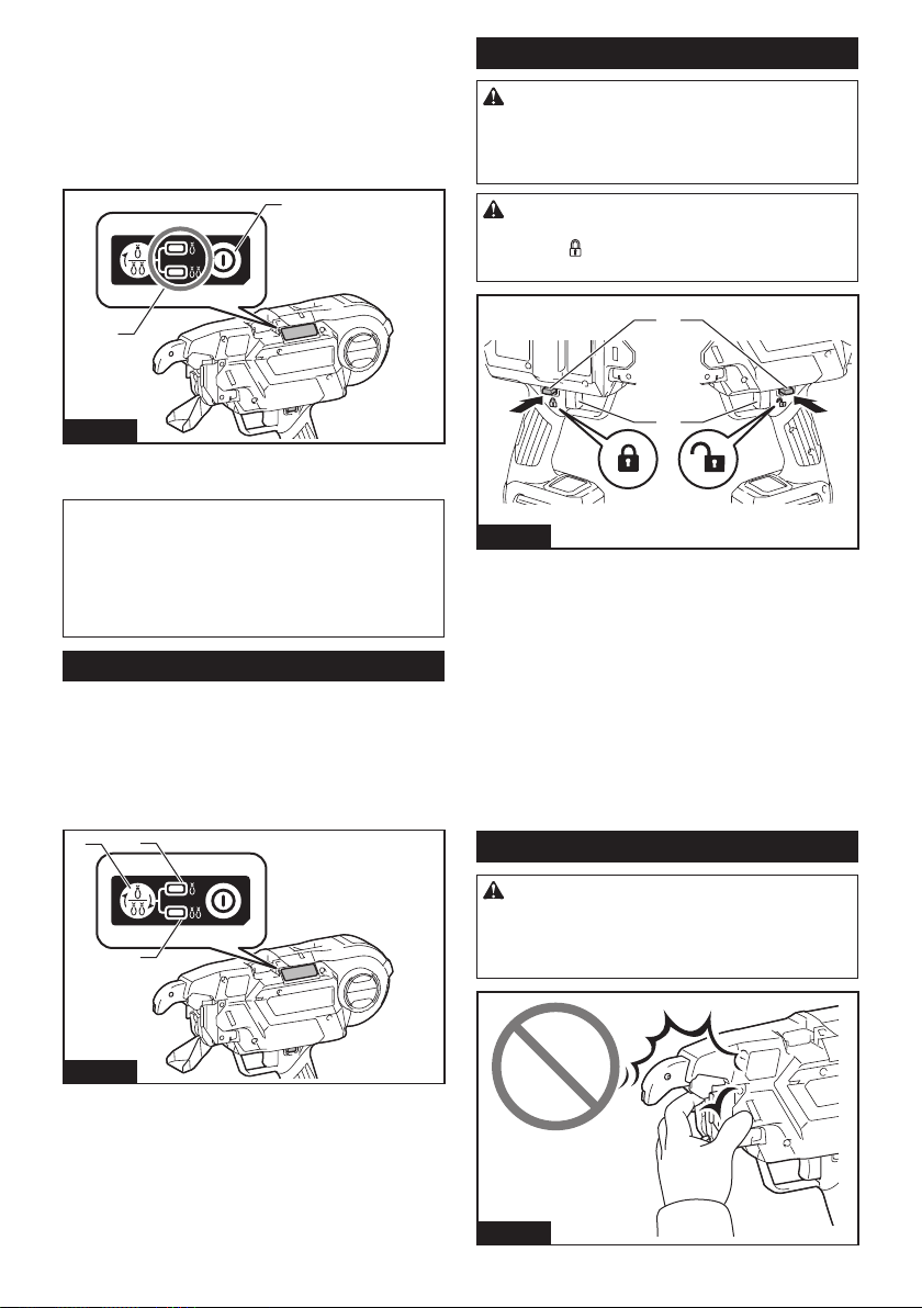
31 ESPAÑOL
Al presionar el botón de encendido/apagado, la herra-
mienta se enciende y la luz indicadora de modo de
amarre se ilumina. A n de ajustar su posición inicial,
la herramienta se activa temporalmente. Una vez com-
pletado el ajuste, la herramienta se detiene automáti-
camente. Al presionar de nuevo el botón de encendido/
apagado, la herramienta se apaga y la luz indicadora
de modo de amarre también.
1
2
Fig.4
► 1. Luz indicadora de modo de amarre 2. Botón de
encendido/apagado
NOTA: La herramienta dispone de una función de
apagado automático. Si el gatillo interruptor no se
acciona durante 10 minutos, la herramienta se apaga
automáticamente para reducir el consumo de energía
de la batería.
NOTA: Para volver a arrancar la herramienta,
conecte de nuevo la alimentación.
Botón de conmutación de modo
Cuando la herramienta se enciende y la luz indicadora
de modo de amarre se ilumina, puede seleccionar el
modo de accionamiento simple o el modo de accio-
namiento continuo mediante el botón de conmutación
de modo. Al conectar de nuevo la alimentación, la
herramienta se enciende en el modo seleccionado la
vez anterior.
2
3
1
Fig.5
► 1. Botón de conmutación de modo 2. Modo de
accionamiento simple 3. Modo de accionamiento
continuo
Accionamiento del interruptor
ADVERTENCIA: Antes de insertar el car-
tucho de batería en la herramienta, compruebe
siempre y cerciórese de que el gatillo interruptor
se acciona debidamente y que vuelve a la posi-
ción “OFF” (apagado) cuando lo suelta.
PRECAUCIÓN: Cuando no vaya a utilizar la
herramienta, oprima el botón de bloqueo del gati-
llo del lado
para bloquear el gatillo interruptor
en la posición de apagado.
2
1
AB
Fig.6
► 1. Gatillo interruptor 2. Botón de bloqueo del gatillo
Para evitar jalar accidentalmente el gatillo interruptor, se suminis-
tra el botón de bloqueo del gatillo. Para arrancar la herramienta,
oprima el botón de bloqueo del gatillo del lado A y jale el gatillo
interruptor. Para detenerla, suelte el gatillo interruptor. Cuando ter-
mine de usarla, oprima el botón de bloqueo del gatillo del lado B.
Cuando se acciona el gatillo interruptor, la herramienta
ejecuta las siguientes operaciones secuenciales como
sigue, y la herramienta se detiene automáticamente.
1. Alimenta el alambre.
2. Corta el alambre.
3. El gancho sujeta y retuerce el alambre.
4. El gancho regresa a su posición original.
Ajuste de la fuerza de amarre
PRECAUCIÓN:
Asegúrese de bloquear el gati-
llo antes de iniciar el ajuste. Al conectar la alimen-
tación, nunca acerque las extremidades o la cara a
las piezas giratorias o de amarre de la punta de la
herramienta. De lo contrario, podría sufrir una lesión.
Fig.7
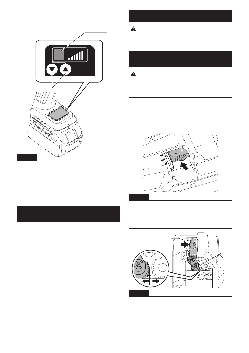
32 ESPAÑOL
Puede regular la fuerza de amarre ajustando el botón
de ajuste de la fuerza de amarre. La fuerza de amarre
se muestra en el panel indicador.
2
1
Fig.8
► 1. Botón de ajuste de la fuerza de amarre 2. Panel
indicador
Si el alambre se rompe, se perderá fuerza de amarre.
Después del amarre, verique que la porción trenzada
no se ha roto.
Si el alambre se ha roto, ajuste la fuerza de amarre
mediante el botón de ajuste de la fuerza de amarre, y
vuelva a amarrar las varillas.
Noticación de la capacidad
restante de la batería
Cuando el voltaje de la batería cae por debajo del nivel
requerido, la herramienta dejará de funcionar, emitirá
un tono de error, y en el panel indicador se visualizará
el número “4”. El tono de error seguirá sonando hasta
que se desconecte la alimentación.
NOTA: Si la temperatura ambiente es extremada-
mente baja, el tono de error puede sonar incluso
cuando la batería contiene suciente energía.
MONTAJE
PRECAUCIÓN: Asegúrese siempre de que la
herramienta esté apagada y el cartucho de batería
haya sido extraído antes de realizar cualquier
trabajo en la misma.
Carga del alambre de amarre
(carrete de alambre)
PRECAUCIÓN: Antes de montar o desmontar
los alambres de amarre y los accesorios, asegú-
rese de desconectar la alimentación, bloquear el
gatillo y extraer el cartucho de batería. De lo con-
trario, se podría ocasionar un accidente.
AVISO: Si se usan alambres que no sean los
auténticos alambres de amarre de Makita, la
herramienta puede funcionar mal.
1. Presione la palanca de liberación y bloquéela con
la palanca de bloqueo.
1
2
Fig.9
► 1. Palanca de liberación 2. Palanca de bloqueo
Cuando se presiona la palanca de liberación, se abre
un espacio entre los engranajes de alimentación
izquierdo y derecho.
1
2
3
Fig.10
► 1. Palanca de liberación 2. Palanca de bloqueo
3. Engranajes de alimentación

33 ESPAÑOL
2. Abra la cubierta del carrete.
1
Fig.11
► 1. Cubierta del carrete
3. Monte el carrete de alambre en la herramienta
según la orientación que se muestra en la gura.
1
Fig.12
► 1. Carrete de alambre
AVISO: Asegúrese de montar el carrete de alam-
bre según la orientación que se muestra en la
gura. Si se monta al revés, el alambre se soltará y
podría quedar retorcido.
4. Desenganche la punta del alambre del gancho del
carrete.
1
Fig.13
► 1. Gancho
5. Enderece la punta del alambre y pase el alambre
por la guía.
1
Fig.14
► 1. Guía
NOTA: Si la punta del alambre está doblada al pasar
por la guía, el alambre se atascará en la herramienta.
NOTA: Si fuerza en exceso el alambre al tratar de
pasarlo por la guía, el alambre se atascará.
6. Tire del alambre aproximadamente 10 mm desde
la punta del brazo de la herramienta.
1
2
Fig.15
► 1. Brazo de la herramienta 2. Aproximadamente
10 mm
AVISO: Si la longitud del alambre jalado es
insuciente, el alambre podría romperse al ama-
rrarlo, o la fuerza de amarre podría verse afectada
debido al número insuciente de envolturas.
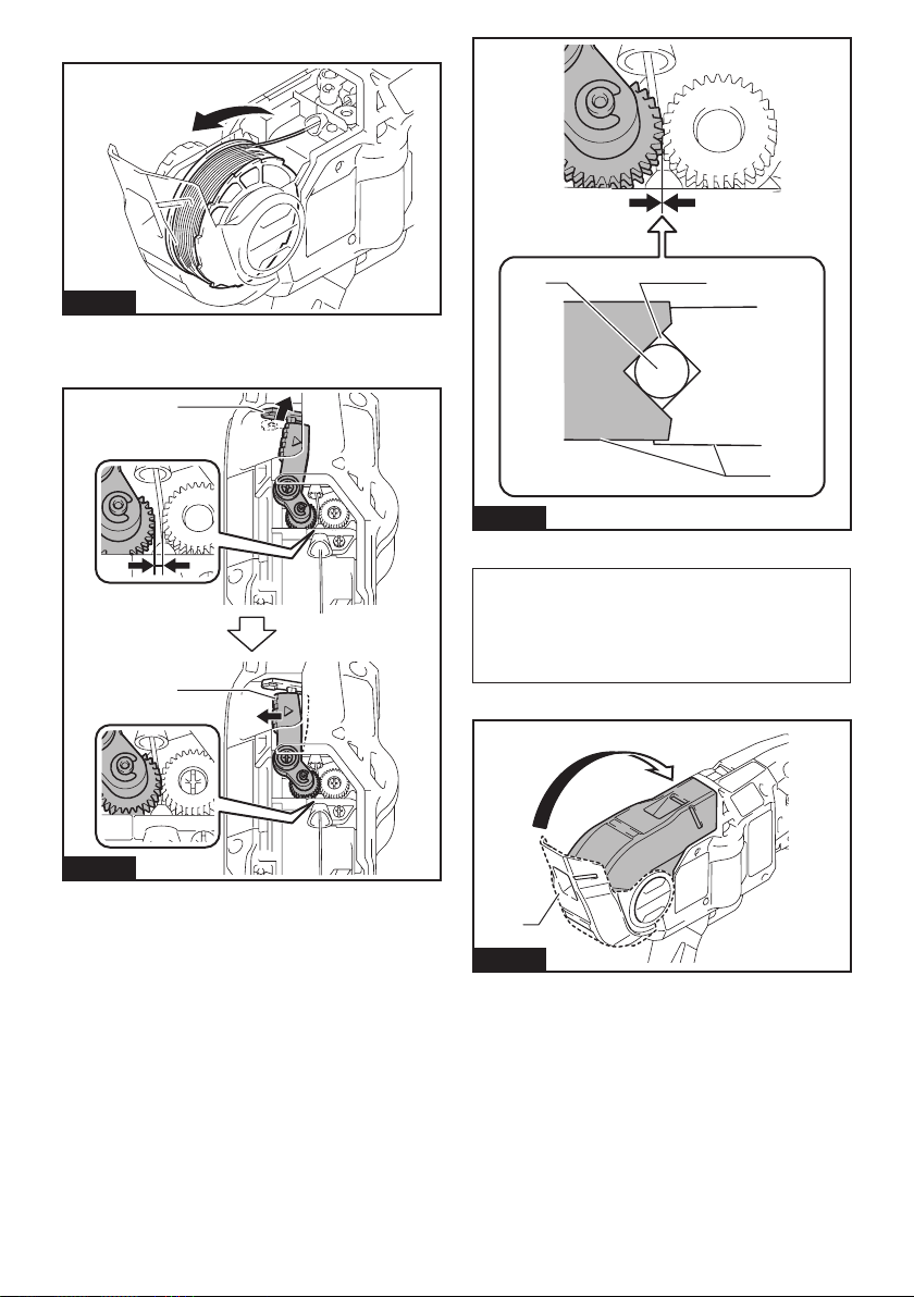
34 ESPAÑOL
7. Rebobine el alambre para tensarlo.
Fig.16
8. Libere la palanca de bloqueo. La palanca de
liberación regresa a su posición, y el alambre queda
sujetado por los engranajes izquierdo y derecho.
2
1
Fig.17
► 1. Palanca de bloqueo 2. Palanca de liberación
1
23
Fig.18
► 1. Engranaje 2. Ruta del alambre 3. Alambre
AVISO: Cuando se suelta la palanca de bloqueo
y los engranajes izquierdo y derecho se engranan
mutuamente, las cavidades de los engranajes
forman un espacio. Este espacio conforma la
ruta del alambre. Asegúrese de que el alambre ha
pasado por esta ruta.
9. Cierre la cubierta del carrete.
1
Fig.19
► 1. Cubierta del carrete
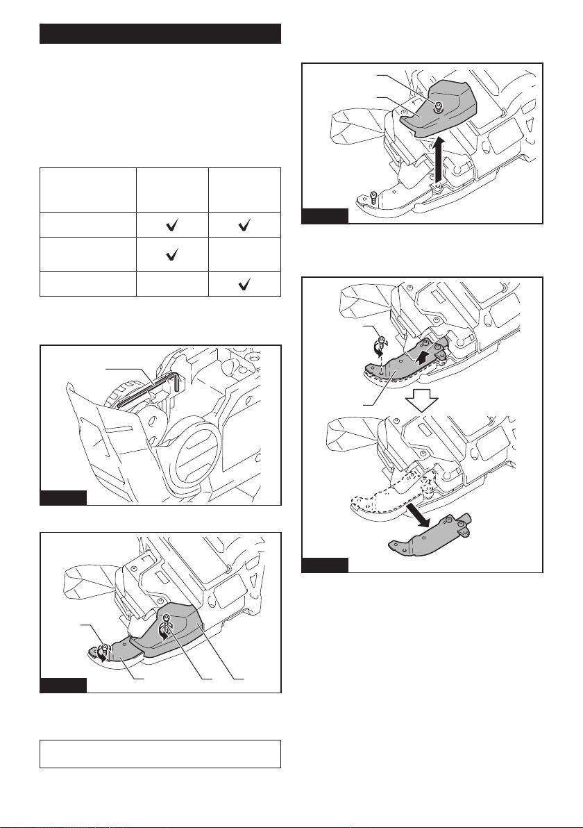
35 ESPAÑOL
Reemplazo de la guía de alambre B
Accesorio opcional
La guía de alambre B (en color plata) en el brazo de
la herramienta se puede reemplazar con una guía de
alambre B opcional (EG) (en color negro) según el tipo
de alambre de amarre a utilizar.
Encuentre la combinación correcta en la tabla a conti-
nuación. Luego, reemplace la guía de alambre B equi-
pada de serie con una guía de alambre B opcional (EG)
si es necesario.
Guía de alambre
B equipada de
serie completa
(plata)
Guía de alambre
B opcional com-
pleta (negro)
Alambre de amarre de
hierro recocido
Alambre de amarre
recubierto con resina
de poliéster
-
Alambre de amarre
galvanizado
-
— : La combinación no es válida.
1. Aoje los pernos A y B con la llave hexagonal
incluida en el paquete de la herramienta.
1
Fig.20
► 1. Llave hexagonal
1
2
3
4
Fig.21
► 1. Perno A 2. Perno B 3. Cubierta de la placa de
contacto 4. Guía de alambre B equipada de serie
(plata)
AVISO: No extraiga a la fuerza ningún perno que
no pueda extraerse con la llave hexagonal.
2. Jale de la cubierta de la placa de contacto hacia
arriba en la dirección de la echa y retírela. El perno B
se extraerá al mismo tiempo.
1
2
Fig.22
► 1. Cubierta de la placa de contacto 2. Perno B
3. Retire el perno A y retire la guía de alambre B
equipada de serie (plata).
1
2
Fig.23
► 1. Perno A 2. Guía de alambre B equipada de serie
(plata)
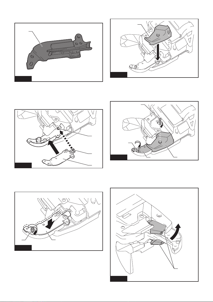
36 ESPAÑOL
4. Reemplace la guía de alambre B equipada de
serie (en color plata) con una guía de alambre B opcio-
nal (EG) (en color negro).
1
Fig.24
► 1. Guía de alambre B opcional (EG) (en color
negro).
5. Alinee el tubo de la herramienta con la ranura del
interior de la guía de alambre B opcional (EG) (en color
negro), y proceda a su ensamblado.
1
2
3
Fig.25
► 1. Tubo 2. Ranura 3. Guía de alambre B opcional
(EG) (negro).
6. Fije la guía de alambre B opcional (EG) (negro)
apretando temporalmente el perno A.
1
2
Fig.26
► 1. Perno A 2. Guía de alambre B opcional (EG)
(negro).
7. Instale la cubierta de la placa de contacto en la
dirección de la echa.
1
Fig.27
► 1. Cubierta de la placa de contacto
8. Fije la guía de alambre B opcional (EG) (negro)
y la cubierta de la placa de contacto rmemente apre-
tando el perno A y el perno B.
1
2
3
4
Fig.28
► 1. Guía de alambre B opcional (EG) (negro).
2. Cubierta de la placa de contacto 3. Perno A
4. Perno B
9.
Después del montaje, verique que la placa de
contacto puede moverse tal como se muestra en la gura.
1
Fig.29
► 1. Placa de contacto
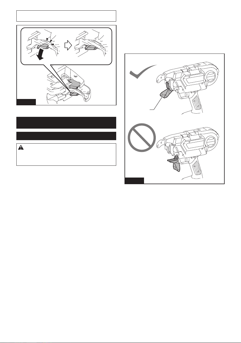
37 ESPAÑOL
NOTA: Si la placa de contacto ha quedado pillada,
presiónela como se muestra en la gura.
Fig.30
OPERACIÓN
Vericación antes del trabajo
PRECAUCIÓN: Si la herramienta tiene algún
problema relacionado con el mecanismo de segu-
ridad, no la use. Si continúa usándola, puede ocurrir
un accidente.
Antes de usar la herramienta, asegúrese de que el
mecanismo de seguridad funciona normalmente. Si la
herramienta se pone en marcha sin el mecanismo de
seguridad en funcionamiento, deje de usar la herra-
mienta inmediatamente. Solicite la reparación en el
centro de servicio Makita de su localidad.
Vericación del seguro del gatillo
La herramienta tiene un seguro de gatillo para impedir
que la herramienta se accione cuando no se pretende
usarla. Bloquee el gatillo y verique que el gatillo inte-
rruptor no puede accionarse.
Vericación de la guía de volutas
Para impedir que el operador toque las piezas girato-
rias o de amarre de la punta de la herramienta por error,
la herramienta no se pondrá en marcha aunque se
accione el gatillo interruptor mientras la guía de volutas
esté abierta. Cuando el operador quita el dedo del gati-
llo interruptor y cierra la guía de volutas, la herramienta
puede funcionar.
1
Fig.31
► 1. Guía de volutas
Vericación de la detección de apertura/
cierre de la guía de volutas
Retire el alambre de amarre, verique la operación
de la herramienta conforme a los pasos siguientes, y
asegúrese de que la herramienta no funciona si la guía
de volutas está abierta.
1. Desconecte la alimentación y deje la guía de
volutas abierta.
2. Conecte la alimentación.
Si la herramienta no funciona y se visualiza el número
“2” en el panel indicador, el estado de la herramienta
es normal. Desconecte la alimentación y cierre la guía
de volutas.
Si la herramienta funciona y no se visualiza ningún
error en el panel indicador, el estado de la herramienta
es anormal. Deje de utilizar la herramienta inmediata-
mente y solicite la reparación en el centro de servicio
de Makita de su localidad.

38 ESPAÑOL
PRECAUCIÓN:
Si abre la guía de volutas y
conecta la alimentación para comprobar el bloqueo de
seguridad, sujete la guía de volutas como se muestra
en la gura. Nunca acerque las extremidades o la cara
a las piezas giratorias o de amarre de la punta de la
herramienta. De lo contrario, podría sufrir una lesión.
Fig.32
Trabajo de amarre
PRECAUCIÓN:
Antes de insertar el cartucho de
batería, asegúrese de apartar los dedos del gatillo interruptor
y de bloquear el gatillo. Si inserta el cartucho de batería mientras
se está jalando el gatillo interruptor, se podría causar un accidente
si se acciona accidentalmente el proceso de amarre del alambre.
PRECAUCIÓN: Al conectar la alimentación,
nunca acerque las extremidades o la cara a las
piezas giratorias o de amarre de la punta de la
herramienta. De lo contrario, podría sufrir una lesión.
PRECAUCIÓN:
Al conectar la alimentación,
nunca toque las piezas giratorias o de amarre de la punta
de la herramienta. De lo contrario, podría sufrir una lesión.
Fig.33
Preparación antes del trabajo
1. Asegúrese de que el cartucho de batería haya
sido extraído y de que el gatillo está bloqueado.
2. Inserte el cartucho de batería en la herramienta y
conecte la alimentación. Al conectar la alimentación, el
alambre se corta automáticamente.
AVISO: Asegúrese de que se enciende la luz indi-
cadora de modo de amarre al conectar la alimen-
tación. Si no se enciende, recargue la batería.
3. Libere el seguro del gatillo.
1
2
3
4
Fig.34
►
1. Botón de seguro del gatillo 2. Gatillo interruptor 3. Botón de
encendido/apagado 4. Luz indicadora de modo de amarre
Modo de accionamiento simple
1. Empuje rmemente el brazo de la herramienta
contra el punto de amarre. Asegúrese de colocar la
herramienta verticalmente sobre las varillas, y presione
el brazo de la herramienta en el punto de amarre en un
ángulo de 45 ° contra las varillas cruzadas.
45°
45°
1
Fig.35
► 1. Brazo de la herramienta

39 ESPAÑOL
2. Jale el gatillo interruptor una vez.
3. El alambre se alimenta y se corta
automáticamente.
4. El gancho sujeta y retuerce el alambre, y luego
retorna a su posición original una vez que los alambres
han sido amarrados.
5. Después del amarre, tenga cuidado de no engan-
char el brazo de la herramienta en las varillas, y luego
jale de la herramienta hacia arriba.
Fig.36
PRECAUCIÓN: Si el alambre se ha adherido
a la pieza de amarre de la punta de la herramienta,
desconecte la alimentación de la herramienta.
Bloquee el gatillo, extraiga el cartucho de batería
y quite el alambre mediante unas tenazas o unas
pinzas.
Fig.37
Modo de accionamiento continuo
1. Conmute el modo de la herramienta desde el
modo de accionamiento simple al modo de acciona-
miento continuo mediante el botón de conmutación de
modo.
1
Fig.38
► 1. Botón de conmutación de modo
2. Libere el seguro del gatillo.
3. Mientras jala del gatillo interruptor, empuje la
herramienta verticalmente contra las varillas, y pre-
sione el brazo de la herramienta a un ángulo de 45
grados contra el punto en el que las varillas se cruzan.
Presione rmemente la placa de contacto contra el
punto de amarre. El alambre se amarrará.
45°
45°
1
Fig.39
► 1. Placa de contacto
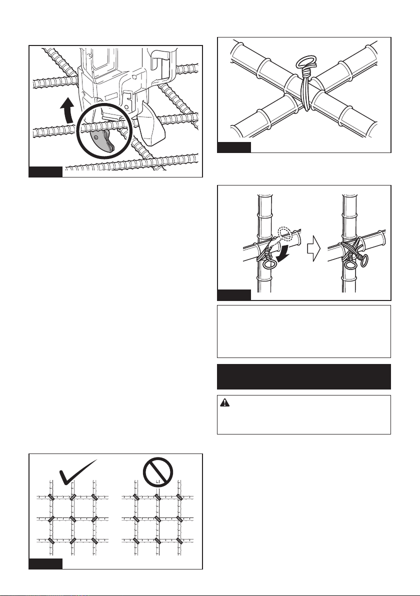
40 ESPAÑOL
4. Después del amarre, tenga cuidado de no engan-
char el brazo de la herramienta en las varillas, y luego
jale de la herramienta hacia arriba.
Fig.40
Precauciones en el trabajo
• Si mueve el brazo de la herramienta desde la
posición de amarre durante el proceso de amarre,
el alambre quedará atascado en el gancho, lo que
podría dar lugar a un amarre incorrecto.
•
Siga presionando la herramienta contra las varillas
hasta que se haya completado el proceso de amarre.
•
No pase al siguiente punto de amarre hasta que se
haya completado el proceso de amarre en curso.
• La pieza giratoria de la punta de la herramienta
(gancho) retuerce el alambre durante el proceso
de amarre. Sujete la empuñadura con rmeza de
manera que la herramienta no le jale el cuerpo.
• No toque los alambres durante el proceso de
amarre.
• Si está repitiendo los procesos de amarre del
alambre en el modo de accionamiento simple,
quite completamente el dedo del gatillo inte-
rruptor. Luego continúe accionando el gatillo
interruptor.
• Si jala el gatillo interruptor cuando ya no queda
alambre, se visualizará un error. Reemplácelo con
un alambre de amarre nuevo y vuelva a encender
la herramienta.
Consejos de amarre
• Incline la herramienta conforme a un ángulo de
45° contra las varillas cruzadas, y amarre el alam-
bre en orientaciones alternas según se muestra
en la gura.
Fig.41
• Ate el alambre sobre las secciones planas (sin
irregularidades) de las varillas cruzadas.
Fig.42
• Si la fuerza de amarre es insuciente, cambie la
orientación de amarre y ejecute el amarre dos
veces para aumentar la fuerza de amarre.
Fig.43
AVISO: Al hacer el segundo amarre, doble el
extremo nal del primer amarre antes de hacer
el segundo. De lo contrario, el alambre puede ser
repelido por segunda vez. Puede quedarse pegado a
la punta de la herramienta, y el gancho puede resul-
tar dañado.
Reemplazo de los alambres de
amarre
PRECAUCIÓN: Al reemplazar el alambre,
asegúrese de desconectar la alimentación, blo-
quear el gatillo y extraer el cartucho de batería.
De lo contrario, se podría ocasionar un accidente.
1. Cuando se haya acabado el alambre, se emitirá
un tono de error y se visualizará el error “1” en el panel
indicador.
2. Bloquee el gatillo, desconecte la alimentación y
extraiga el cartucho de batería.

41 ESPAÑOL
3. Presione la palanca de liberación y bloquéela con
la palanca de bloqueo.
1
2
Fig.44
► 1. Palanca de liberación 2. Palanca de bloqueo
4. Retire el carrete de alambre de la herramienta.
NOTA: Cuando el alambre se acaba en condiciones
normales, quedan enrollados en el carrete unos 20
cm de alambre. En este estado, reemplace el carrete
de alambre por uno nuevo.
Si resulta difícil retirar el carrete de alambre de la herra-
mienta, siga los pasos a continuación.
1. Inserte el cartucho de batería en la herramienta
y conecte la alimentación. El alambre se alimenta y se
corta automáticamente.
2. Bloquee el gatillo, desconecte la alimentación y
extraiga el cartucho de batería.
3. Quite las roturas de alambre mediante unas tena-
zas o unas pinzas.
MANTENIMIENTO
PRECAUCIÓN: Asegúrese siempre de que la
herramienta esté apagada y el cartucho de batería
extraído antes de intentar realizar una inspección
o mantenimiento.
AVISO: Nunca use gasolina, bencina, diluyente
(tíner), alcohol o sustancias similares. Puede que
esto ocasione grietas o descoloramiento.
Para mantener la SEGURIDAD y FIABILIDAD del pro-
ducto, las reparaciones, y cualquier otra tarea de man-
tenimiento o ajuste deberán ser realizadas en centros
de servicio autorizados o de fábrica Makita, empleando
siempre repuestos Makita.
Limpieza de la unidad cortadora
Cuando la herramienta se usa, pueden adherirse polvo
y partículas de alambre a la unidad cortadora. En tal
caso, limpie la unidad cortadora siguiendo el proce-
dimiento a continuación. La limpieza debe realizarse
cada vez que consuma una caja de carrete. (50 pzas.)
Uso del cepillo de alambre
1. Abra la cubierta del carrete.
1
Fig.45
► 1. Cubierta del carrete
2. Presione la palanca de liberación y bloquéela con
la palanca de bloqueo.
1
2
Fig.46
► 1. Palanca de liberación 2. Palanca de bloqueo
3. Pase el cepillo de alambre a través de la guía.
Cuando inserte el cepillo de alambre, sujételo a medio
recorrido y empújelo dentro la guía poco a poco.
1
Fig.47
► 1. Cepillo de alambre
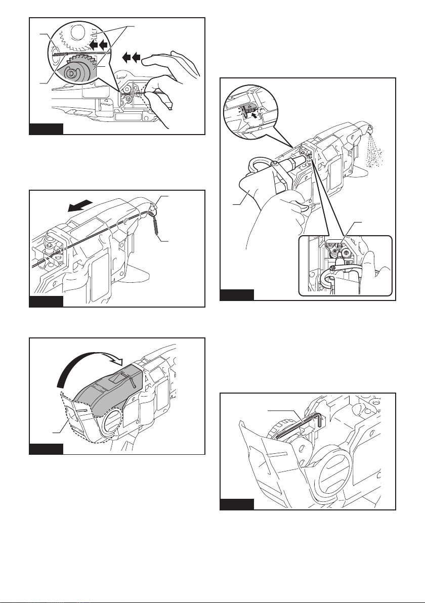
42 ESPAÑOL
1
2
3
Fig.48
► 1. Engranaje 2. Guía 3. Cepillo de alambre
4. Empuje el cepillo de alambre hasta que su
extremo superior sobresalga desde la punta del brazo
de la herramienta. Luego, saque el cepillo de alambre.
Bastará realizar esta acción una vez.
1
2
Fig.49
► 1. Brazo de la herramienta 2. Cepillo de alambre
5. Cierre la cubierta del carrete.
1
Fig.50
► 1. Cubierta del carrete
Uso de la pistola sacudidora de aire
Abra la cubierta del carrete, presione la palanca de libe-
ración y bloquéela con la palanca de bloqueo. Luego,
acerque la pistola sacudidora de aire a la guía y sople
aire. Asegúrese de que el aire salga por la punta del
brazo de la herramienta.
1
2
Fig.51
► 1. Pistola sacudidora de aire 2. Guía
Limpieza con el desmontaje
Si la unidad cortadora se obstruye o un alambre queda
atrapado dentro, desmonte las piezas y límpielas.
Desmontaje y limpieza
1. Aoje los pernos A y B con la llave hexagonal
incluida en el paquete de la herramienta.
1
Fig.52
► 1. Llave hexagonal
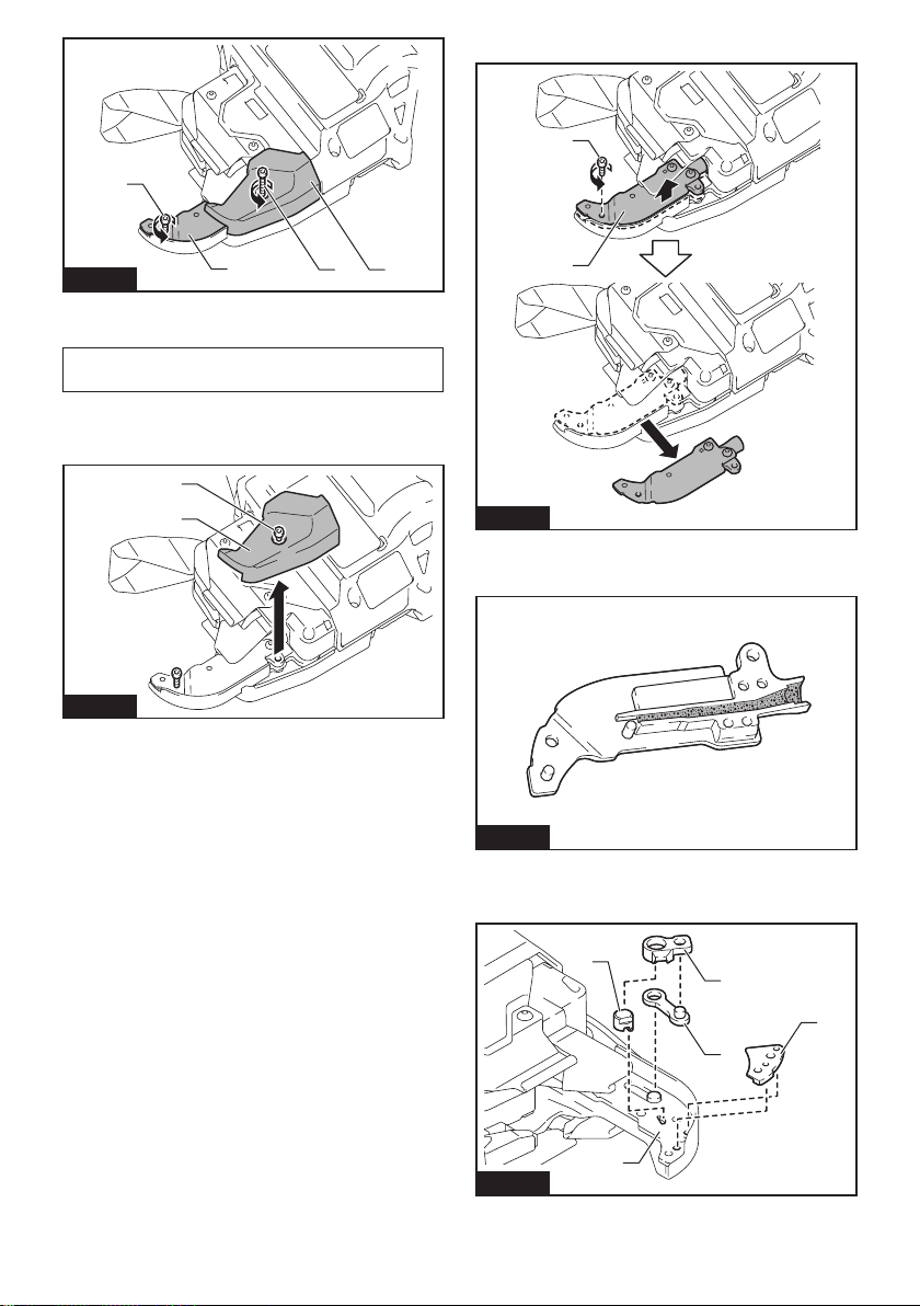
43 ESPAÑOL
1
2
3
4
Fig.53
► 1. Perno A 2. Perno B 3. Cubierta de la placa de
contacto 4. Guía de alambre B
AVISO: No extraiga a la fuerza ningún perno que
no pueda extraerse con la llave hexagonal.
2. Jale de la cubierta de la placa de contacto hacia
arriba en la dirección de la echa y retírela. El perno B
se extraerá al mismo tiempo.
1
2
Fig.54
► 1. Cubierta de la placa de contacto 2. Perno B
3. Retire el perno A y extraiga la guía de alambre B.
1
2
Fig.55
► 1. Perno A 2. Guía de alambre B
4.
Dele la vuelta a la guía de alambre B y limpie el interior.
Fig.56
5. Retire la placa superior, la cortadora B, el brazo
articulado A y la cortadora A de la placa de brazo A. Y
luego límpielos.
1
2
3
4
5
Fig.57
► 1. Placa superior 2. Cortadora B 3. Brazo articulado
A 4. Cortadora A 5. Placa de brazo A
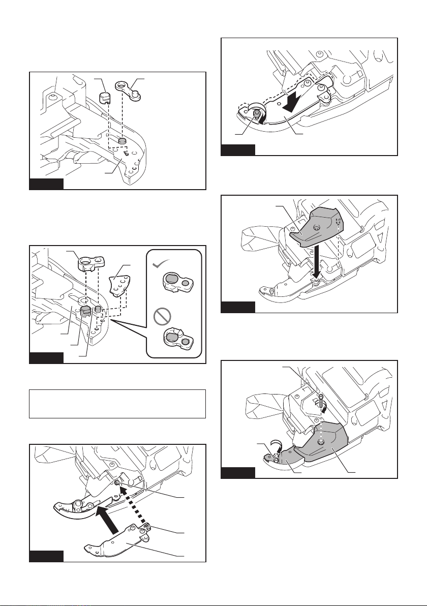
44 ESPAÑOL
Montaje
Una vez terminada la limpieza, monte las piezas
siguiendo el procedimiento a continuación.
1.
Instale la cortadora A y el brazo articulado A de
manera que se ajusten a la forma de la placa de brazo A.
1
2
3
Fig.58
►
1. Cortadora A 2. Brazo articulado A 3. Placa de brazo A
2. Instale la cortadora B y la placa superior sobre la
placa de brazo A.
(Instale la cortadora B sobre la cortadora A y el brazo
articulado A).
1
2
4
3
5
Fig.59
► 1. Cortadora B 2. Placa superior 3. Placa de brazo
A 4. Cortadora A 5. Brazo articulado A
AVISO: Oriente el saliente de la cortadora B
hacia abajo e instale la cortadora tal como se
muestra en la gura.
3. Alinee el tubo de la herramienta con la ranura del
interior de la guía de alambre B, y móntelos.
1
2
3
Fig.60
► 1. Tubo 2. Ranura 3. Guía de alambre B
4. Acople la guía de alambre B apretando temporal-
mente el perno A.
1
2
Fig.61
► 1. Perno A 2. Guía de alambre B
5. Instale la cubierta de la placa de contacto en la
dirección de la echa.
1
Fig.62
► 1. Cubierta de la placa de contacto
6. Acople rmemente la guía de alambre B y la
cubierta de la placa de contacto apretando el perno A y
el perno B.
1
2
3
4
Fig.63
► 1. Guía de alambre B 2. Cubierta de la placa de
contacto 3. Perno A 4. Perno B

45 ESPAÑOL
7. Después del montaje, verique que la placa de
contacto puede moverse tal como se muestra en la
gura.
1
Fig.64
► 1. Placa de contacto
NOTA: Si la placa de contacto ha quedado pillada,
presiónela como se muestra en la gura.
Fig.65
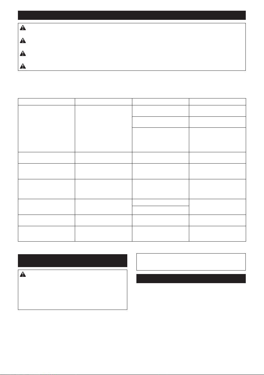
46 ESPAÑOL
Indicación de error y tono de error
PRECAUCIÓN: Durante la inspección, asegúrese de bloquear el gatillo, desconectar la alimentación y
extraer el cartucho de batería. De lo contrario, se podría ocasionar un accidente.
PRECAUCIÓN: Al conectar la alimentación, nunca acerque las extremidades o la cara a las piezas
giratorias o de amarre de la punta de la herramienta. De lo contrario, podría sufrir una lesión.
PRECAUCIÓN: Al conectar la alimentación, nunca toque las piezas giratorias o de amarre de la punta
de la herramienta. De lo contrario, podría sufrir una lesión.
PRECAUCIÓN:
Si suena un tono de error, o si la herramienta no funciona bien, deje de usarla inmediatamente.
Indicación y tono de error
Si se produce un error, sonará un tono de error y se visualizará un número de error en el panel indicador. Consulte la tabla
siguiente y tome las medidas apropiadas. Si el error persiste, pida a su centro de servicio autorizado de Makita que se lo repare.
Indicación Síntoma Causa posible Solución
1 La herramienta deja de
funcionar.
El alambre se ha acabado. Cargue más alambre de
amarre.
El alambre de amarre no se ha
cargado.
Cargue el alambre de amarre.
La alimentación de alambre
ha fallado.
Compruebe la orientación del
alambre de amarre.
Descargue el alambre de ama-
rre y vuélvalo a cargar.
Limpie la ruta del alambre.
2 La herramienta deja de
funcionar.
La guía de volutas está abierta. Cierre la guía de volutas.
3 La herramienta no ejecuta el
proceso de amarre en el modo
de accionamiento continuo.
La placa de contacto ha que-
dado pillada.
Libere la placa de contacto que
ha quedado pillada.
4 La herramienta no arranca.
La herramienta deja de
funcionar.
La batería se ha descargado.
La temperatura del cartucho de
batería es anormalmente alta.
Recargue la batería.
Enfríe el cartucho de batería.
Reemplace el cartucho de bate-
ría con uno que esté recargado.
5 La herramienta deja de
funcionar.
El motor está sobrecargado. Determine la causa de la
obstrucción de la rotación del
motor y solucione el problema.
Falla del motor
6 La herramienta deja de
funcionar.
La temperatura de la herra-
mienta es anormalmente alta.
Enfríe la herramienta.
7 La herramienta no arranca.
La herramienta deja de
funcionar.
Falla de la herramienta Solicite la reparación en un
centro de servicio autorizado
de Makita.
ACCESORIOS OPCIONALES
PRECAUCIÓN: Estos accesorios o aditamen-
tos están recomendados para utilizarse con su
herramienta Makita especicada en este manual.
El empleo de cualquier otro accesorio o aditamento
puede conllevar el riesgo de lesiones personales.
Utilice los accesorios o aditamentos solamente para
su n establecido.
Si necesita cualquier ayuda para más detalles en
relación con estos accesorios, pregunte a su centro de
servicio local Makita.
• Alambre de amarre
• Guía de alambre B completa (EG)
• Cepillo de alambre
• Mango de extensión
• Batería y cargador originales de Makita
NOTA: Algunos de los artículos en la lista pueden
incluirse en el paquete de la herramienta como acce-
sorios estándar. Éstos pueden variar de país a país.
GARANTÍA LIMITADA DE MAKITA
Ésta Garantía no aplica para México
Consulte la hoja de la garantía anexa para ver los
términos más vigentes de la garantía aplicable a este
producto. En caso de no disponer de esta hoja de
garantía anexa, consulte los detalles sobre la garantía
descritos en el sitio web de su país respectivo indicado
a continuación.
Estados Unidos de América: www.makitatools.com
Canadá: www.makita.ca
Otros países: www.makita.com

47

Some dust created by power sanding, sawing, grinding, drilling, and other
construction activities contains chemicals known to the State of California
to cause cancer, birth defects or other reproductive harm. Some examples
of these chemicals are:
• lead from lead-based paints,
• crystalline silica from bricks and cement and other masonry products, and
• arsenic and chromium from chemically-treated lumber.
Your risk from these exposures varies, depending on how often you do this
type of work. To reduce your exposure to these chemicals: work in a well
ventilated area, and work with approved safety equipment, such as those
dust masks that are specially designed to filter out microscopic particles.
WARNING
< USA only >
ADVERTENCIA
Algunos polvos creados por el lijado, aserrado, esmerilado, taladrado y
otras actividades de la construcción contienen sustancias químicas
reconocidas por el Estado de California como causantes de cáncer, defectos
de nacimiento y otros peligros de reproducción. Algunos ejemplos de estos
productos químicos son:
• plomo de pinturas a base de plomo,
• sílice cristalino de ladrillos y cemento y otros productos de albañilería, y
• arsénico y cromo de maderas tratadas químicamente.
El riesgo al que se expone varía, dependiendo de la frecuencia con la que
realice este tipo de trabajo. Para reducir la exposición a estos productos
químicos: trabaje en un área bien ventilada y póngase el equipo de seguridad
indicado, tal como las máscaras contra polvo que están especialmente
diseñadas para filtrar partículas microscópicas.
< Sólo en los Estados Unidos >
Makita Corporation
3-11-8, Sumiyoshi-cho,
Anjo, Aichi 446-8502 Japan
www.makita.com
885876-941
XRT02-1
EN, ESMX
20220308