Loading ...
Loading ...
Loading ...
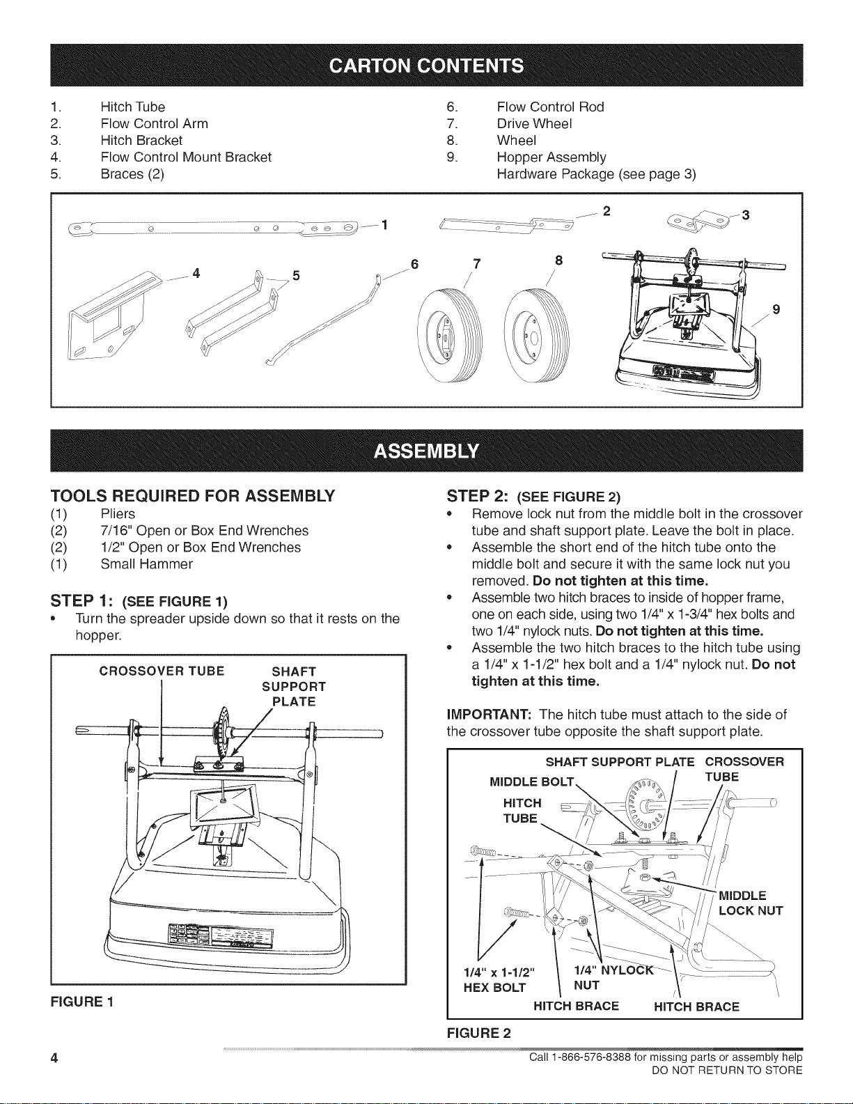
1. Hitch Tube 6. Flow Control Rod
2. Flow Control Arm 7. Drive Wheel
3. Hitch Bracket 8. Wheel
4. Flow Control Mount Bracket 9. Hopper Assembly
5. Braces (2) Hardware Package (see page 3)
j6 7 8
...........4 5if /J
/
TOOLS REQUIRED FOR ASSEMBLY
(!) Pliers
(2) 7/16" Open or Box End Wrenches
(2) 1/2" Open or Box End Wrenches
(1) Small Hammer
STEP 1: (SEE FIGURE 1)
*Turn the spreader upside down so that it rests on the
hopper.
CROSSOVER TUBE SHAFT
I SUPPORT
PLATE
FIGURE 1
STEP 2: (SEE FIGURE 2)
,Remove lock nut from the middle bolt in the crossover
tube and shaft support plate. Leave the bolt in place.
,Assemble the short end of the hitch tube onto the
middle bolt and secure it with the same lock nut you
removed. Do not tighten at this time.
,Assemble two hitch braces to inside of hopper frame,
one on each side, using two 1/4" x 1-3/4" hex bolts and
two 1/4" nylock nuts. Do not tighten at this time.
,Assemble the two hitch braces to the hitch tube using
a 1/4" x 1-1/2" hex bolt and a 1/4" nylock nut. Do not
tighten at this time.
iMPORTANT: The hitch tube must attach to the side of
the crossover tube opposite the shaft support plate.
SHAFT SUPPORTPLATE CROSSOVER
MIDDLE BOLT TUBE
HITCH
TUBE
"MIDDLE
LOCK NUT
1/4" × 1=1/2" 1/4"
HEX BOLT NUT
HITCH BRACE HITCH BRACE
4
FIGURE 2
Call 1-866-576-8388 for missing parts or assembly help
DO NOT RETURN TO STORE
Loading ...
Loading ...
Loading ...