
Villa Door Station
User’s Manual
V1.0
.0

I
Foreword
General
This manual introduces how to configure the villa door station (hereinafter referred to as "VTO") on
the web interface.
Safety Instructions
The following categorized signal words with defined meaning might appear in the Manual.
Signal Words Meaning
CAUTION
Indicates a potential risk which, if not avoided, could result in
property damage, data loss, lower performance, or unpredictable
result.
NOTE
Provides additional information as the emphasis and supplement to
the text.
Revision History
Version Revision Content Release Date
V1.0.0 First release. January 2021
About the Manual
The manual is for reference only. If there is inconsistency between the manual and the actual
product, the actual product shall prevail.
We are not liable for any loss caused by the operations that do not comply with the manual.
The manual would be updated according to the latest laws and regulations of related
jurisdictions. For detailed information, refer to the paper manual, CD-ROM, QR code or our
official website. If there is inconsistency between paper manual and the electronic version, the
electronic version shall prevail.
All the designs and software are subject to change without prior written notice. The product
updates might cause some differences between the actual product and the manual. Please
contact the customer service for the latest program and supplementary documentation.
There still might be deviation in technical data, functions and operations description, or errors
in print. If there is any doubt or dispute, we reserve the right of final explanation.
Upgrade the reader software or try other mainstream reader software if the manual (in PDF
format) cannot be opened.
All trademarks, registered trademarks and the company names in the manual are the properties
of their respective owners.
Please visit our website, contact the supplier or customer service if there is any problem
occurring when using the device.
If there is any uncertainty or controversy, we reserve the right of final explanation.

II
Important Safeguards and Warnings
The following description is the correct application method of the VTO. Read the manual carefully
before use, to prevent danger and property loss. Strictly conform to the manual during use and keep
it properly after reading.
Operating Requirements
Do not expose the device to direct sunlight or heat source.
Do not install the device in a humid or dusty environment.
Horizontally install the device at stable places to prevent it from falling.
Do not drip or splash liquids onto the device, or put on the device anything filled with liquids.
Install the device at well-ventilated places and do not block its ventilation opening.
Use the device only within rated input and output range.
Do not dismantle the device by yourself.
Transport, use and store the device within allowed humidity and temperature range.
Power Requirements
Use electric wires recommended in your area, and within its rated specification.
Use power supply that meets SELV (safety extra low voltage) requirements, and supply power
with rated voltage that conforms to Limited Power Source in IEC60950-1. For specific power
supply requirements, see the label on the device.
Appliance coupler is a disconnecting device. During normal use, keep an angle that facilitates
operation.

III
Table of Contents
Foreword ............................................................................................................................................................ I
Important Safeguards and Warnings .............................................................................................................. II
1 Initializing the VTO ........................................................................................................................................ 1
2 Login and Resetting Password ..................................................................................................................... 2
Login ............................................................................................................................................................................................... 2
Resetting Password ................................................................................................................................................................... 2
3 Main Interface ................................................................................................................................................ 4
4 Local Settings ................................................................................................................................................ 5
Basic ................................................................................................................................................................................................ 5
Video & Audio .............................................................................................................................................................................. 6
Access Control Settings ........................................................................................................................................................... 8
4.3.1 Local ................................................................................................................................................................................... 8
4.3.2 RS-485 ............................................................................................................................................................................... 9
4.3.3 Password Management .............................................................................................................................................. 9
System .......................................................................................................................................................................................... 10
Security ........................................................................................................................................................................................ 11
Wiegand ....................................................................................................................................................................................... 12
Onvif User .................................................................................................................................................................................... 13
Upload File .................................................................................................................................................................................. 13
5 Household Setting ....................................................................................................................................... 15
VTO No. Management ............................................................................................................................................................ 15
VTH Management .................................................................................................................................................................... 16
5.2.1 Adding Room Number .............................................................................................................................................. 16
5.2.2 Issuing Access Card .................................................................................................................................................... 17
5.2.3 Issuing Fingerprint ..................................................................................................................................................... 18
VTS Management ..................................................................................................................................................................... 19
IPC Setting .................................................................................................................................................................................. 20
Status ............................................................................................................................................................................................ 21
Publish Information ................................................................................................................................................................. 22
5.6.1 Send Info ........................................................................................................................................................................ 22
5.6.2 History Info .................................................................................................................................................................... 22
6 Network ........................................................................................................................................................ 24
Basic .............................................................................................................................................................................................. 24
6.1.1 TCP/IP .............................................................................................................................................................................. 24
6.1.2 Port ................................................................................................................................................................................... 24
6.1.3 P2P .................................................................................................................................................................................... 25
UPnP .............................................................................................................................................................................................. 25
6.2.1 Enabling UPnP Services ............................................................................................................................................ 25
6.2.2 Adding UPnP Services ............................................................................................................................................... 25
SIP Server .................................................................................................................................................................................... 26
Firewall ......................................................................................................................................................................................... 27
7 Log Management ........................................................................................................................................ 29
Cybersecurity Recommendations ............................................................................................. 30

1
1 Initializing the VTO
For first-time login or after resetting the VTO, you need to initialize it on the web interface.
Power on the VTO.
Go to the default IP address (192.168.1.108) of the VTO.
Make sure that the IP address of your PC is in the same network segment as the VTO.
Device initialization
Enter and confirm the password, and then click Next.
Enter an email address for resetting password.
Click Next, and then click OK.

2
2 Login and Resetting Password
Login
Before login, make sure that the PC is in the same network segment as the VTO.
Go to the IP address of the VTO in the browser.
For first-time login, enter the default IP (192.168.1.108). If you have multiple VTOs, we
recommend changing the default IP address (Network > Basic) to avoid conflict.
Enter "admin" as username and the password you set during initialization, and then click
Login.
Login
Resetting Password
On the login interface, click Forgot Password?, and then click Next.
Reset the password
Scan the QR code, and then you will get a string of numbers and letters.
Send the string to the email: support_gpwd@htmicrochip.com, and then the security code
will be sent to the email address configured during initialization.
Enter the security code in the input box, and then click Next.

3
If you did not set an email address during initialization, contact your supplier or
customer service for help.
The security code will be valid only for 24 hours upon receipt.
If you enter the wrong security code for 5 consecutive times, your account will be
locked for 5 minutes.
Enter and confirm the new password, and then click OK.

4
3 Main Interface
Main interface
Table 3-1 Main interface introduction
No. Function Description
1 General function
: Change the password and your email address.
: Go to the main interface.
: Log out, restart the VTO or restore the VTO to factory
settings.
If you restore the VTO to factory settings, all data except external
storage will be deleted. You can format the SD card to delete the
data in it.
2 VTO information
View the information of the VTO and the system.
3 System information
4
Configuration
manager
Export or import VTO configuration or user information.
5 Function
Configure parameters for different functions.
Interface and function might vary with models. The actual product
shall prevail.
5
4 Local Settings
This chapter introduces the detailed configuration of the VTO.
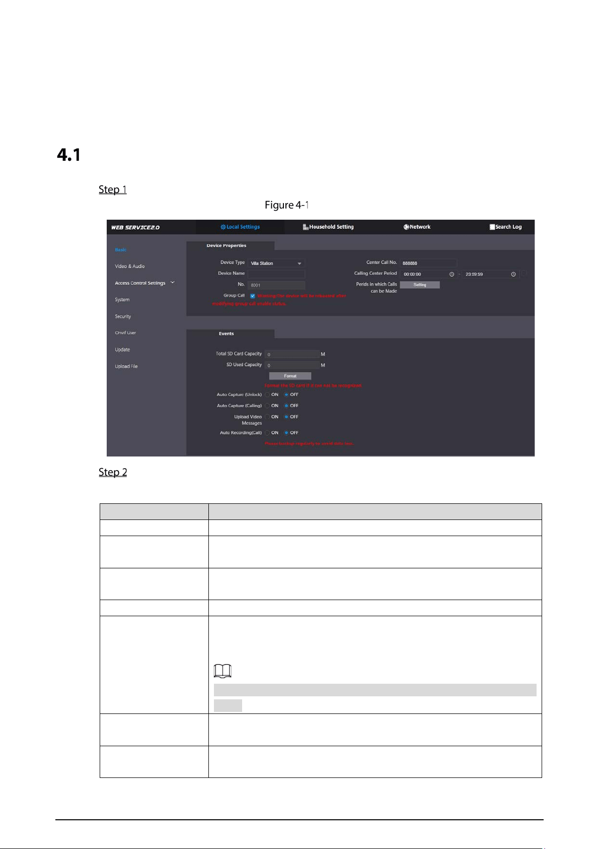
Basic
Select Local Settings > Basic.
Basic
Configure the parameters.
Table 4-1 Basic parameter description
Parameter Description
Device Type
Select Villa Station or Small Apartment as needed.
Center Call No.
The default phone number for the management center is 888888, and
you can set it to any number with up to 9 digits.
Device Name
When other devices are monitoring this VTO, the device name will appear
on the monitoring image.
Calling Center Period Time period in which the management center can be called.
No.
Used to differentiate each VTO, and we recommend setting it according
to unit or building number, and then you can add VTOs to the SIP server
by using their numbers.
You can change the number of the VTO when it is not working as the SIP
server.
Periods in which Calls
can be Made
Configure the time if you only want to receive calls during a specific
period.
Group Call
Enable it on the VTO that works as the SIP server, and when a main VTH
receives a call, all extension VTHs will also receive the call.

6
Parameter Description
Total SD Card
Capacity
Displays the total and used capacity of the SD card. You can click Format
to delete all the data in the SD card. SD Used Capacity
Format
Auto Capture
(Unlock)
When the door is unlocked, the VTO will take two snapshots and save
them to the SD card.
Auto Capture (Calling)
Take a snapshot and save it in the SD card of the VTO when the VTO is
calling.
Upload Video
Messages
When enabled:
If an SD card is inserted in both the VTH and VTO, the video message
will be saved both in the SD cards of the VTH and the VTO.
If an SD card is only inserted in the VTH or the VTO, the video
message will be saved only in the SD card of the VTH or the VTO.
If no SD card is inserted in the VTH or VTO, no video message will be
saved.
Auto Recording (Call)
Take recording when the VTO is in a call, and save the recording in the SD
card of the VTO.
Click Save.
Video & Audio
Configure the video format and quality, and audio of the VTO.
Select Local Settings > Video & Audio.
Video and audio
Configure the parameters, which will take effect upon change.

7
Table 4-2 Video parameter description
Parameter Description
Main/Sub
Stream
Video
Format
Select different resolution as needed:
1080P: 1920 × 1080.
720P: 1280 × 720.
WVGA: 800 × 480.
QVGA: 320 × 240.
D1: 720 × 480.
CIF: 352 × 288.
Frame Rate
The larger the value, the smoother the video, but it requires more
bandwidth.
Bitrate Rate
The larger the value, the better the video quality, but it requires more
bandwidth.
Status
Scene Mode
Select as needed according to the lighting condition. Auto is selected
by default.
Compensati
on Mode
BLC: Back light compensation. Improve the clarity of the target in
the image.
WDR: Wide dynamic range. Enhance the brightness of dark areas,
and reduce the brightness of bright areas to improve the image.
HLC: High light compensation.
Reduce the brightness of the
strong spots to improve the overall image.
Video
Standard
Select PAL or NTSC according to your area.
PAL is mostly used in China and Europe, and NTSC primarily in the
United States and Japan.
Image
Brightness The larger the value, the brighter the image.
Contrast Larger value for more contrast between bright and dark areas.
Hue
Make the color brighter or darker. The default value is made by the
light sensor, and we recommend keeping it default.
Saturation The larger the value, the thicker the color.
Gamma
Changes the picture brightness and improves the picture dynamic
range in a non-linear way. The larger the value, the brighter the image.
Gain
Adjustment
Amplify the video signal to increase image brightness. If the value is
too large, there will be more noise in the image.
Mirror Display the image with left and right side reversed.
Flip Display the image upside down.
Display Time Display the current time and date on the video image.
Audio
Control
— Turn on or off each type of sound.
Volume
Control
Microphone
Volume
Adjust the volume as needed.
Speaker
Volume
8
Access Control Settings
This section introduces how to configure the two locks connected to the lock port or the RS-485 port
of the VTO.
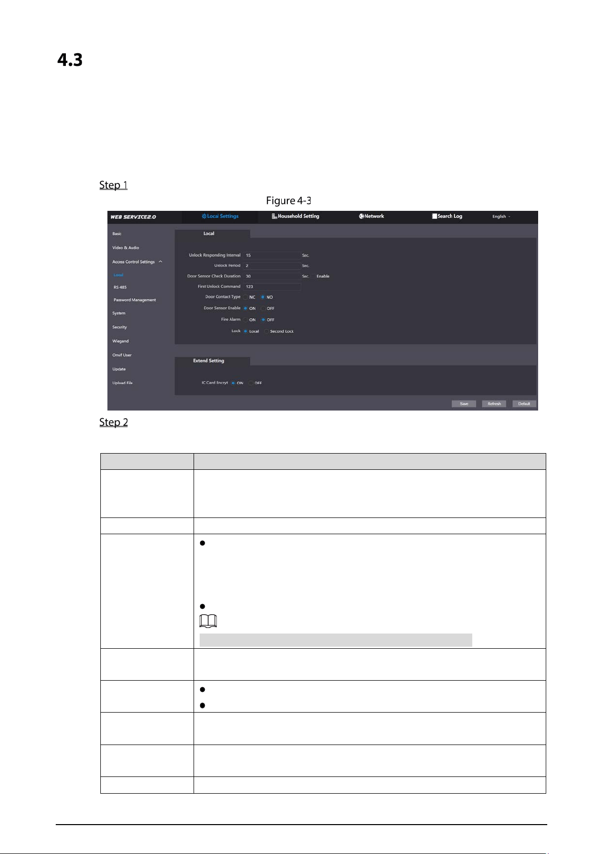
4.3.1 Local
Select Local Settings > Access Control Settings.
Local
Configure the parameters.
Table 4-3 Local access control parameter description
Parameter Description
Unlock
Responding
Interval
The door can only be unlocked again after the interval.
Unlock Period The time during which the lock stays unlocked.
Door Sensor
Check Duration
Enable it, and the door will not be locked until the door sensors contact
each other. If the door is unlocked longer than the Door Sensor Check
Duration, the door sensor alarm will be triggered, and the alarm will be
sent to the management center.
Disable it, and then the door will be locked after the Unlock Period.
You need to install a door contact to configure this parameter.
First/Second
Unlock Command
You can connect a third-party phone, such as a SIP phone, to the VTO, and
use the command to open the door remotely.
Door Contact
Type
NC: Normally closed.
NO: Normally open.
Door Sensor
Enable
Synchronize door sensor status to indoor monitors (VTHs).
Fire Alarm
If turned on, you can connect an alarm device to the port that is originally for
the door contact, but you cannot use the door contact function.
Lock Non-remote methods, such as password or card, will unlock the lock you
9
Parameter Description
select.
IC Card Encrypt Access cards issued by the VTO will be encrypted and unclonable.
Click Save.
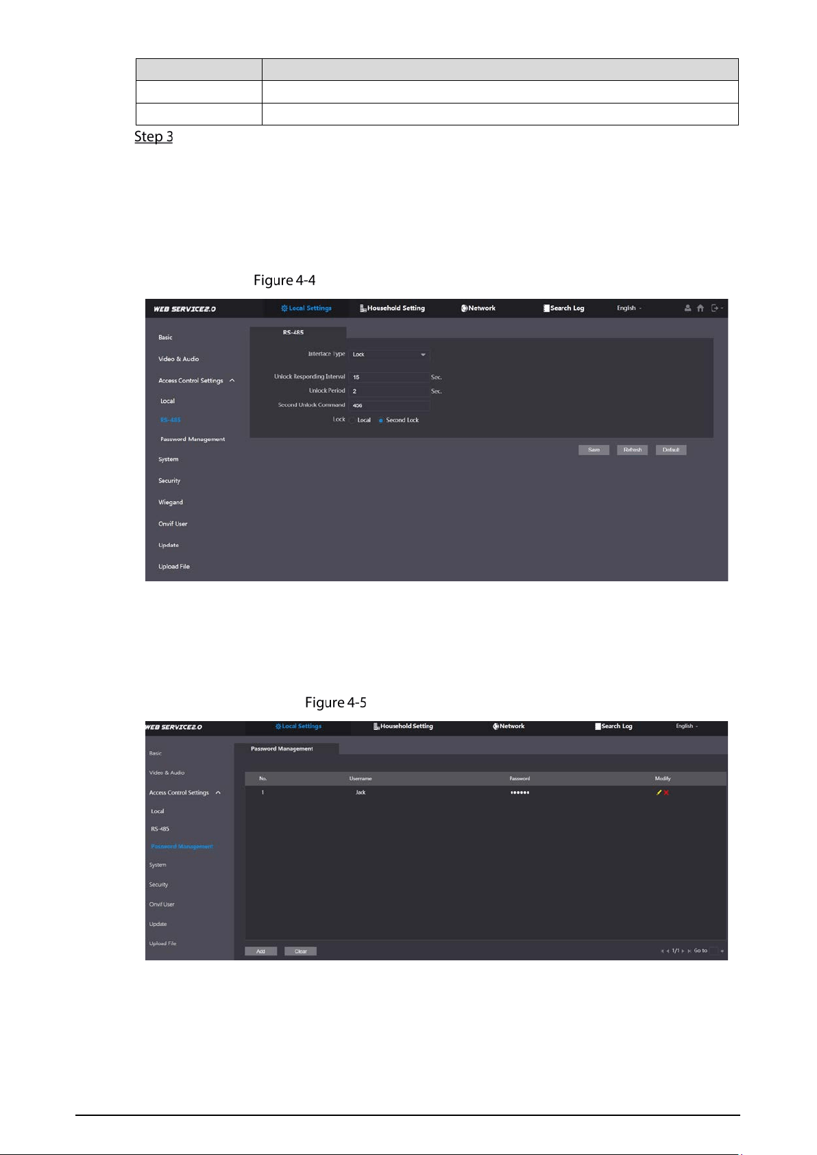
4.3.2 RS-485
Select Local Settings > Access Control Settings, and then configure the parameters of the lock
connected through the RS-485 port. See Table 4-3 for parameter description.
Lock connected through the RS-485 port
4.3.3 Password Management
Add a username and password used to unlock the door.
Password management
10
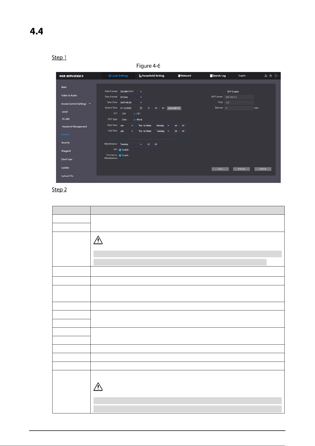
System
Configure time parameters, NTP server, and more.
Select Local Settings > System.
System
Configure the parameters.
Table 4-4 System parameter description
Parameter Description
Date Format
Select a format as needed.
Time Format
System Time
Changing system time might cause problems on video searching and information
publication. Turn off video recording and auto snapshot before changing it.
Time Zone
Configure the time zone as needed.
Sync with PC Synchronize the VTO system time with your PC.
DST
Daylight saving time. If it is applicable to your area, you need to enable it, and
then configure DST type, start time and end time.
DST Type
Select Date or Week as needed, and then configure the specific period.
Start Time
Configure the start time and end time of DST.
End Time
NTP Enable
Enable NTP and enter the IP address of the NTP server, and then the VTO will
syncronize time with the NTP server automatically.
NTP Server
Port NTP server port number.
Interval VTO time update cycle. 30 minutes at most.
Maintenance Define the time when the VTO will restrart automatically.
SSH
You can connect debugging devices to the VTO through SSH protocol.
We recommend turning it off, and turn on security mode and outbound service
information protection. See "4.5 Security". Otherwise, the VTO might be exposed
11
Parameter Description
to security risks and data leakage.
Emergency
Maintenance
Enable it for fault analysis and repair.
This function will occupy 8088 and 8087 ports.
Click Save.
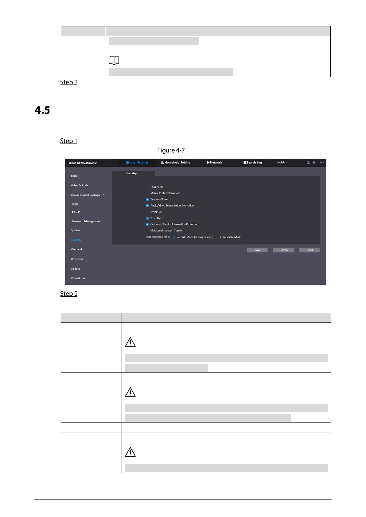
Security
Configure functions that involve device security.
Select Local Settings > Security.
Security
Configure the parameters.
Table 4-5 Security parameter description
Parameter Description
CGI Enable
Enable the use of CGI command.
We recommend turning it off. Otherwise, the VTO might be exposed to
security risks and data leakage.
Mobile Push
Notification
Send information to the app on the smartphone.
We recommend turning it off if you do not need this function. Otherwise,
the VTO might be exposed to security risks and data leakage.
Password Reset If turned off, you will not be able to reset password.
Audio/Video
Transmission
Encryption
Encrypt all data during voice or video call.
We recommend turning it on. Otherwise, the VTO might be exposed to
12
Parameter Description
security risks and data leakage.
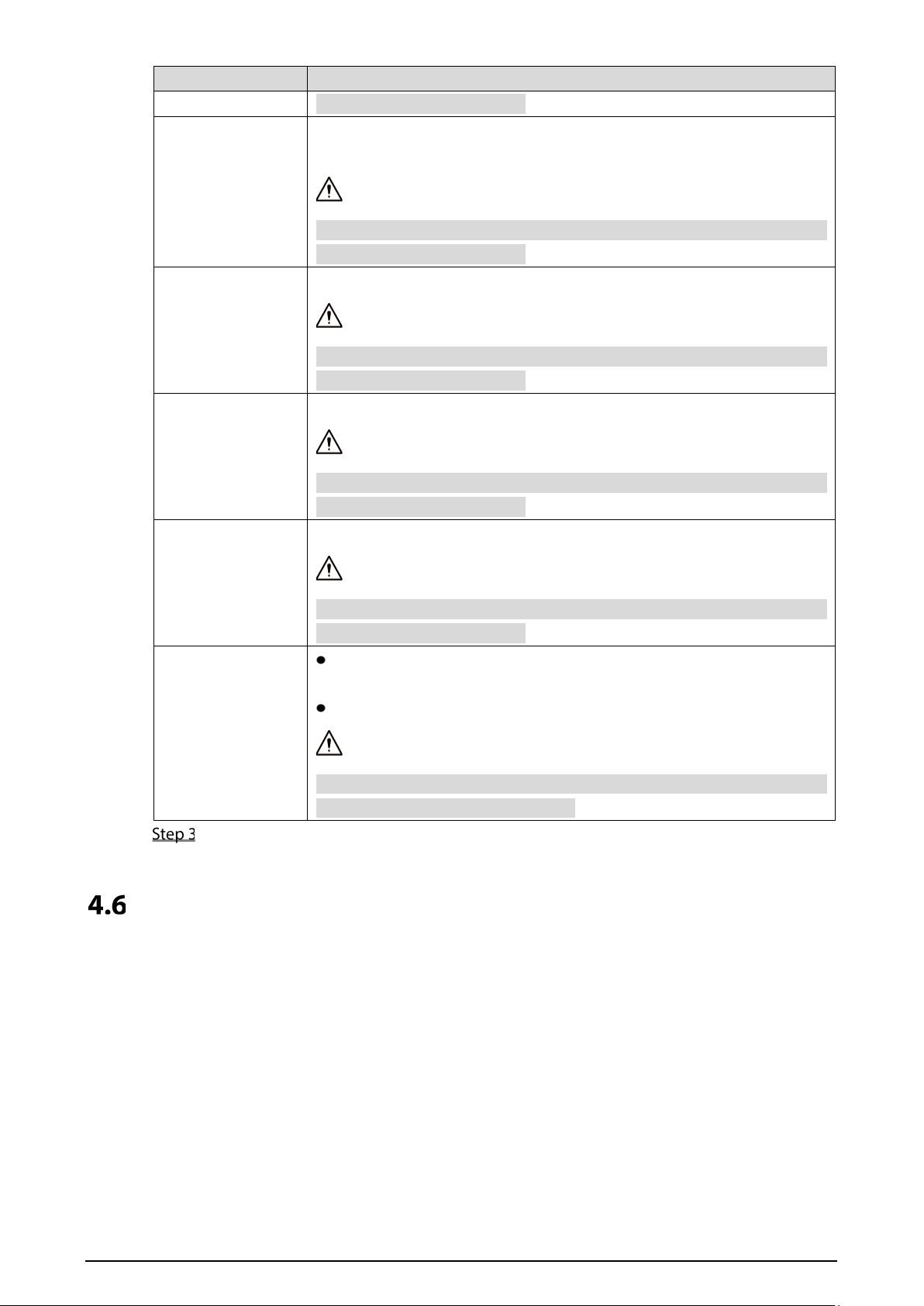
ONVIF On
Allow third-party to pull video stream of the VTO through the ONVIF
protocol.
We recommend turning it off. Otherwise, the VTO might be exposed to
security risks and data leakage.
RTSP Over TSL
Output encrypted bit stream through RTSP.
We recommend turning it on. Otherwise, the VTO might be exposed to
security risks and data leakage.
Outbound Service
Information
Protection
Protect your passwords.
We recommend turning it on. Otherwise, the VTO might be exposed to
security risks and data leakage.
Multicast/Broadcast
Search
Enable it and the VTO will be found by other devices.
We recommend turning it off. Otherwise, the VTO might be exposed to
security risks and data leakage.
Authentication
Mode
Security Mode (recommended):
Support logging in with Digest
authentication.
Compatible Mode: Use the old login method.
We recommend the security mode. Compatible mode might expose the
VTO to security risks and data leakage.
Click Save.
Wiegand
Configure the parameters as needed when connected to other devices, such as a card reader with a
Wiegand port.

13
Wiegand
Onvif User
Add accounts for devices to monitor the VTO through the ONVIF protocol.
If you delete an account, it cannot be undone.
Select Local Settings > Onvif User.
Click Add.
Add an ONVIF user
Enter the information, and then click Save.
ONVIF devices can now monitor the VTO by using the account. See the user’s manual of the
ONVIF device for details.
Upload File
Upload audio file to change the sound when calling, unlocking the door, and more.
Select Local Settings > Upload File.
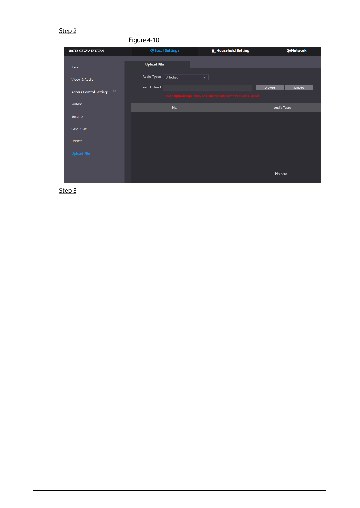
14
Select an audio type, and then click Browse to select the audio file as needed.
Change the sound prompt
Click Upload.
15
5 Household Setting
This chapter introduces how to add, modify, and delete VTO, VTH, VTS, and IPC, and how to send
messages from the SIP server to VTOs and VTHs when the VTO works as the SIP server. If you are
using other servers as the SIP server, see the corresponding manual for details.
To configure SIP server parameters, see "6.3 SIP Server" for details.
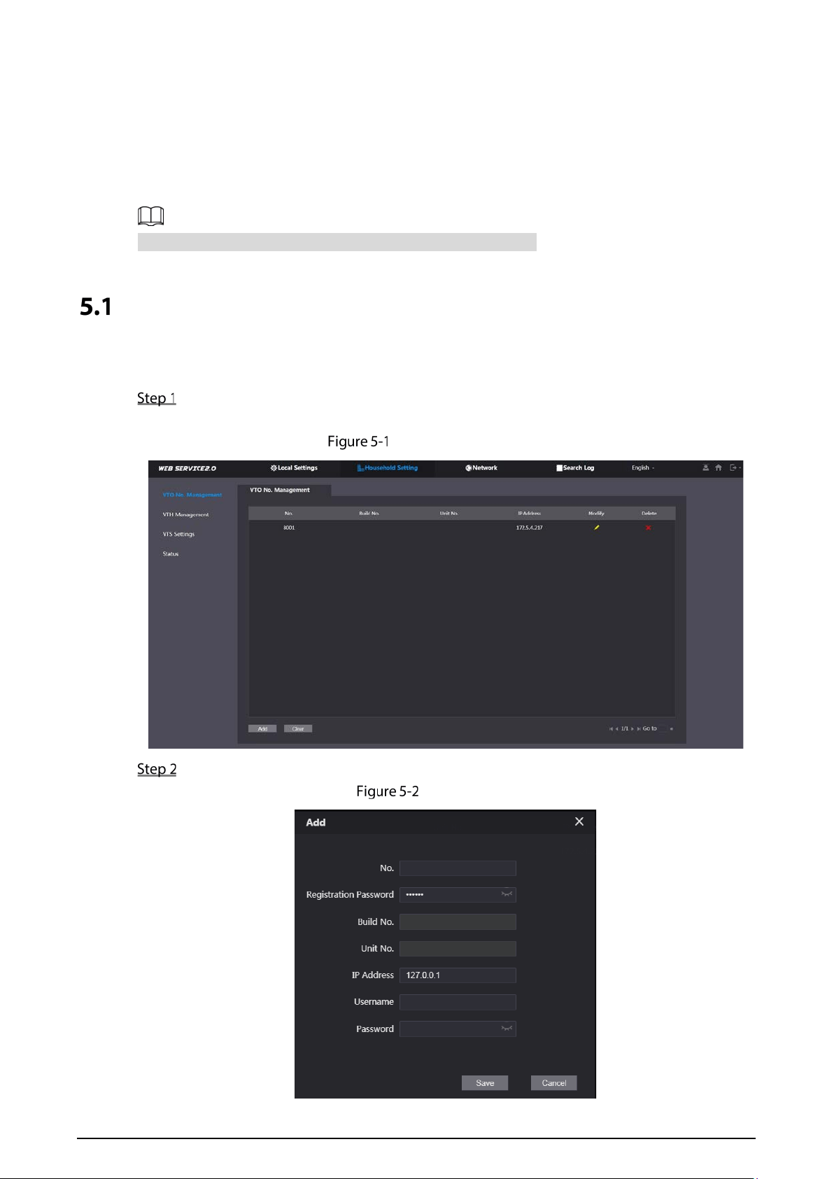
VTO No. Management
You can add VTOs to the SIP server, and all the VTOs connected to the same SIP server can call each
other.
Log in to the web interface of the VTO working as the SIP server, and then select Household
Setting > VTO No. Management.
VTO management
Click Add.
Add VTO
16
Configure the parameters.
The SIP server must be added.
Table 5-1 Add VTO configuration
Parameter Description
No. The VTO number you configured. See Table 4-1 for details.
Registeration
Password
Keep it default.
Build No.
Available only when other servers work as the SIP server.
Unit No.
IP Address IP address of the VTO.
Username
Web interface login username and password of the VTO.
Password
Click Save.
Click or to modify or delete a VTO, or Clear to delete all added VTOs, but the one
that you have logged in to cannot be modified or deleted.
VTH Management
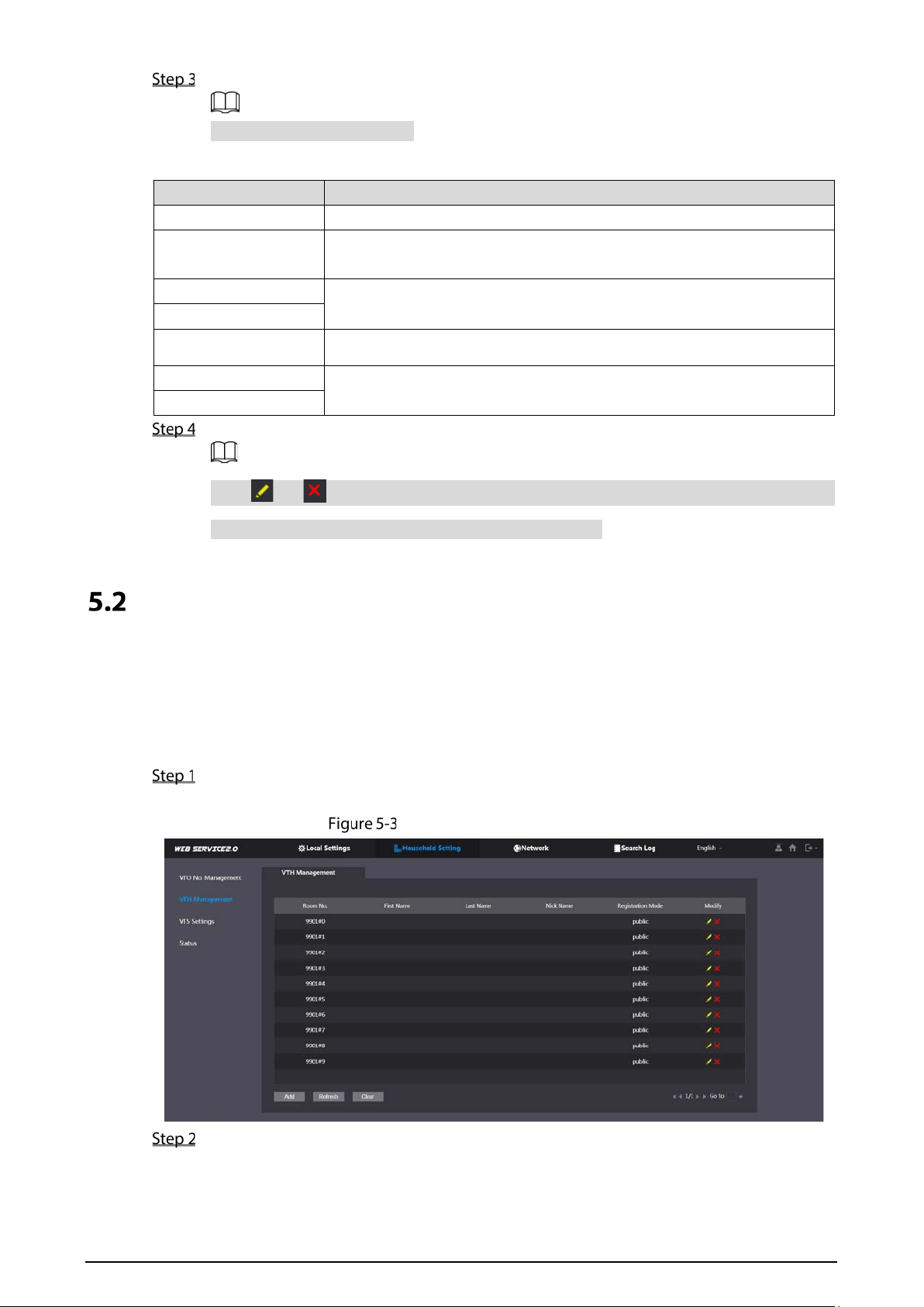
5.2.1 Adding Room Number
You can add room numbers to the SIP server, and then configure the room number on the VTHs to
connect them to the network.
Log in to the web interface of the SIP server, and then select Household Setting > VTH
Management.
Room number management
Click Add.
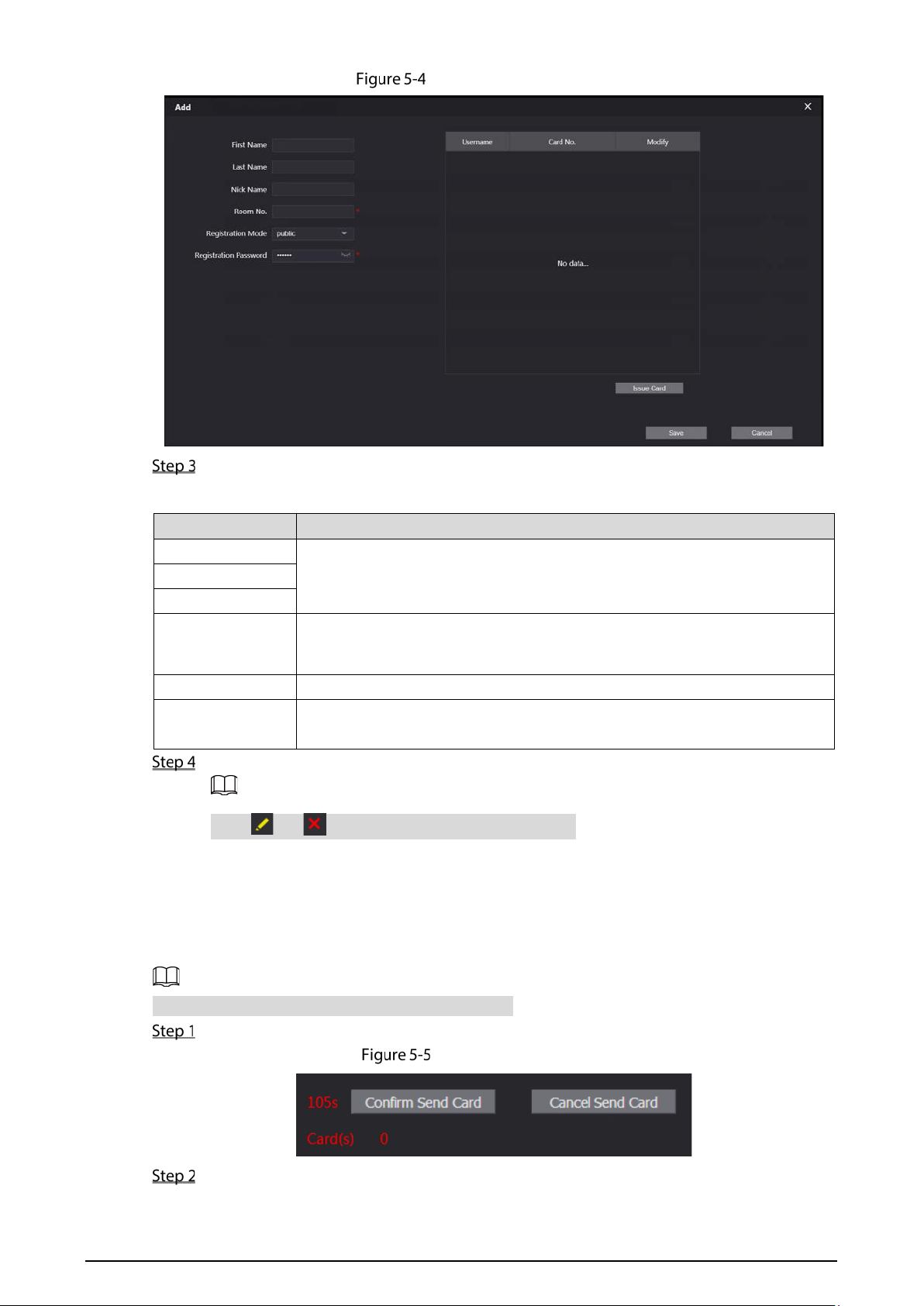
17
Add a room number
Configure the parameters.
Table 5-2 Room information
Parameter Description
First Name
Enter the information you need to differentiate each room.
Last Name
Nick Name
Room No.
Enter a room number, and then configure the number on a VTH to connect
to connect it to the network.
Registeration Type
Select public.
Registeration
Password
Keep it default.
Click Save.
Click or to modify or delete a room number.
5.2.2 Issuing Access Card
Issue an access card to unlock the door of a room.
To use this function, the VTO must have a card reader.
Select Household Setting > VTH Management, click Add, and then click Issue Card.
Countdown notice
Swipe the card on the VTO.

18
Issue card
Enter the username, click Save, and then click Confirm Send Card.
Issued access card
Other Operations
Click to set it as the main card, and then the icon changes to . The main card can be
used to issue access cards for this room on the VTO.
Click to set it to loss, and then the icon changes to . The lost card cannot be used to
open the door.
Click or to modify the username or delete the card.
5.2.3 Issuing Fingerprint
Issue fingerprints to unlock the door of a room.
To use this function, the VTO must have a fingerprint scanner.
Select Household Setting > VTH Management, click Add, and then click Issue
Fingerprint.
Issue fingerprint
Enter a username, assign unlock permission as needed, and then click Save.
19
Press your fingerprint on the scanner.
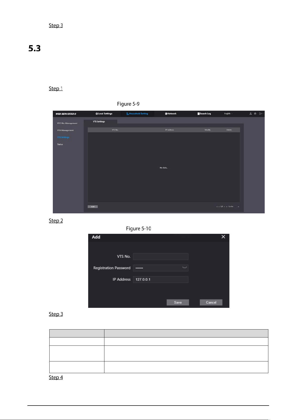
VTS Management
You can add a VTS to the SIP server, and then it can be used as the management center. It can also
manage, call, or receive calls from all the VTOs and VTHs in the network. See the corresponding user's
manual for details.
Log in to the web interface of the VTO working as the SIP server, and then select Household
Setting > VTS Settings.
VTS management
Click Add.
Add VTS
Configure the parameters.
Table 5-3 Add VTS configuration
Parameter Description
VTS No. The number of the VTS.
Registeration
Password
Keep it default.
IP Address VTS IP address.
Click Save.
20
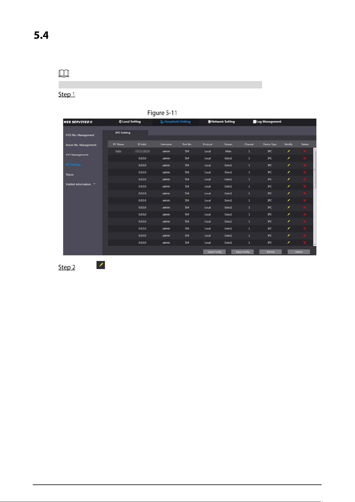
IPC Setting
You can add IPC and NVR to the VTO working as the SIP server, and then all the connected VTHs can
monitor them.
Interfaces might vary with different products. The actual interface shall prevail.
Log in to the web interface of the VTO working as the SIP server, and then select Household
Setting > IPC Setting.
IPC setting
Click .

21
Add IPC
Configure the parameters.
Table 5-4 Add IPC configuration
Parameter Description
IPC Name Enter the name that identifies the IPC.
IP Address IP address of the IPC.
Username
Web interface login username and password of the device.
Password
Port Keep it default.
Protocol
Select Local or Onvif.
Stream Type
Main: Better video quality but requires more bandwidth.
Extra1: Smoother video with poorer quality, but requires less bandwidth.
Channel The number of the channels that a device supports.
Device Type Select the one as needed.
MediaEncrypt
Select ON if the IPC to be added is encrypted.
Click Save.
Other Operations
Export Config: Export the device information to your PC.
Import Config: Import device information.
Status
You can view the online status and IP addresses of all the connected devices.
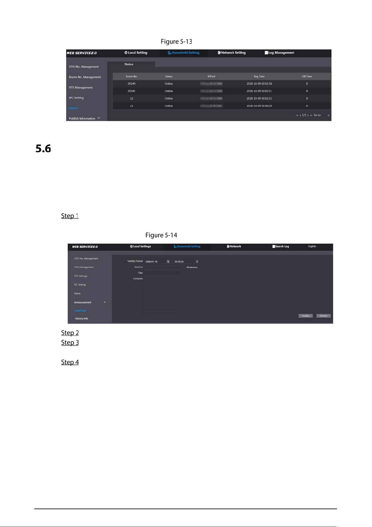
22
Log in to the web interface of the SIP server, and then select Household Setting > Status.
Status
Publish Information
You can send messages from the SIP server to VTH devices, and view message history.
5.6.1 Send Info
Log in to the web interface of the SIP server, and then select Household Setting > Publish
Information > Send Info.
Send information
Specify the Validity Period that the message will be valid.
Enter the VTO number or VTH number, or select All devices to send the message to all the
devices in the network, and then enter the title and content of your message.
Click Confirm.
5.6.2 History Info
You can view the information of sent messages.
Log in to the web interface of the SIP server, select Household Setting > Publish Information >
History Info.
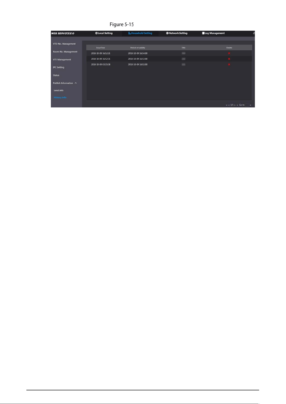
23
History information

24
6 Network
This chapter introduces how to configure the network parameters.
Basic
6.1.1 TCP/IP
You can modify the IP address, subnet mask, default gateway, and DNS of the VTO.
Select Network > Basic.
TCP/IP and port
Configure the parameters, and then click Save.
The VTO will restart, and you need to modify the IP address of your PC to the same network
segment as the VTO to log in again.
6.1.2 Port
Table 6-1 Parameter description
Parameter Description
Port
80 by default. If already used, choose any number from 1025 to 65535 as
needed. You can enter http://VTO IP address:Port to log in to the VTO.
HTTPS Port
Enable it and click Save. You can now enter https://VTO IP address:HTTPS Port to

25
Parameter Description
log in to the VTO.
TCP/UDP Port
Used for accessing the VTO with devices in other networks. See "6.2 UPnP" for
details.
Create Server
Certificate
The unique digital identification of VTO for the SSL protocol. For first time use
or after changing the IP address of the VTO, you need to go through this
process.
If you delete the certificate that has been created, it cannot be undone.
Download Root
CERT
If you are using a PC that has never logged in to the VTO,
you need to
download the root certificate, double-click to install it, and then you can use
the HTTPS function mentioned above.
If you delete the certificate that has been installed, it cannot be undone.
6.1.3 P2P
Enable the P2P function, and then you can scan the QR code with your phone to add the VTO to the
app on your smartphone. See the quick start guide for details.
UPnP
When the VTO works as the SIP server, you can configure the UPnP function to allow WAN devices to
log in to the VTO.
Preparation
Enable the UPnP function on the router, and then configure a WAN IP address for the router.
Connect the VTO to the LAN port of the router.
6.2.1 Enabling UPnP Services
Select Network > UPnP.
Enable the services listed as needed.
Select Enable.
Click Save.
6.2.2 Adding UPnP Services
Select Network > UPnP.
Click Add.
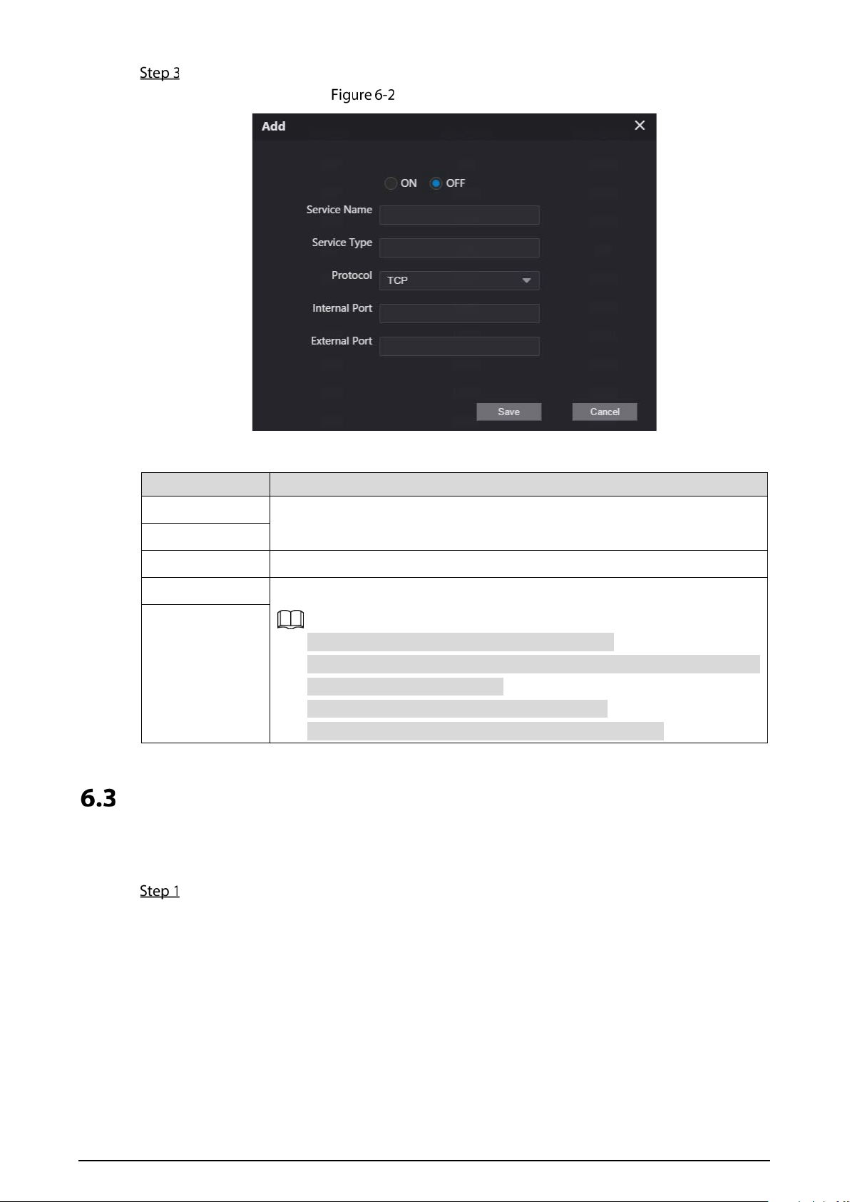
26
Configure the parameters as needed.
Add a UPnP service
Table 6-2 Parameter description
Parameter Description
Service Name
Enter the information as needed.
Service Type
Protocol
Select TCP or UDP as needed.
Internal Port Use port number from 1024 through 5000.
Do not use port number 1–1023 to avoid conflict.
If you need to configure this function for multiple devices, make sure
that the ports are not the same.
The port number you use must not be occupied.
The internal and external port number must be the same.
External Port
SIP Server
There must be a SIP server in the network for all connected VTOs and VTHs to call each other. You can
use a VTO or other servers as the SIP server.
Select Network > SIP Server.

27
SIP Server
Select a server type as needed.
The VTO you have logged in as the SIP server:
Enable SIP Server, and click Save, and then the VTO will restart. You can add VTOs and
VTHs to this VTO. See the details in "5 Household Setting".
If the VTO you have logged in does not SIP server, do not enable SIP Server; otherwise
the connection will fail.
If another VTO works as the SIP server:
Do not enable SIP server. Set Server Type to VTO, configure the parameters, and then
click Save.
Table 6-3 SIP server configuration
Parameter Description
IP Addr. VTO IP address.
Port
5060 by default when VTO work as SIP server.
5080 by default when the platform works as SIP server.
Username
Keep it default.
Password
SIP Domain VDP.
SIP Server Username
Web interface login username and password of the VTO.
SIP Server Password
If other servers work as the SIP server:
Select the Server Type as needed, and then see the corresponding manual for details.
Firewall
You can enable different firewall types to control network access to the VTO.
Select Network > Firewall.

28
Firewall
Select one or more firewall types, and then enable them.
Configure the parameters.
Table 6-4 Firewall type description
Type Description
Network Access
Select either Allowlist or Blocklist, and then add an IP address or segment
which is allowed or denied to access the VTO.
PING Prohibited The VTO will not response to ping to avoid ping attacks.
Anti-semijoin Protects the VTO performance by blocking excessive SYN packets.

29
7 Log Management
Select Search Log. You can search for different logs, and export them to your PC as needed.
If storage is full, the oldest records will be overwritten. Back up the records as needed.

30
Cybersecurity Recommendations
Cybersecurity is more than just a buzzword: it’s something that pertains to every device that is
connected to the internet. IP video surveillance is not immune to cyber risks, but taking basic steps
toward protecting and strengthening networks and networked appliances will make them less
susceptible to attacks. Below are some tips and recommendations on how to create a more secured
security system.
Mandatory actions to be taken for basic device network security:
1. Use Strong Passwords
Please refer to the following suggestions to set passwords:
The length should not be less than 8 characters;
Include at least two types of characters; character types include upper and lower case
letters, numbers and symbols;
Do not contain the account name or the account name in reverse order;
Do not use continuous characters, such as 123, abc, etc.;
Do not use overlapped characters, such as 111, aaa, etc.;
2. Update Firmware and Client Software in Time
According to the standard procedure in Tech-industry, we recommend to keep your device
(such as NVR, DVR, IP camera, etc.) firmware up-to-date to ensure the system is equipped
with the latest security patches and fixes. When the device is connected to the public
network, we recommend enabling the "auto-check for updates" function to obtain timely
information of firmware updates released by the manufacturer.
We suggest that you download and use the latest version of client software.
"Nice to have" recommendations to improve your device network security:
1. Physical Protection
We suggest that you perform physical protection to device, especially storage devices. For
example, place the device in a special computer room and cabinet, and implement well-done
access control permission and key management to prevent unauthorized personnel from
carrying out physical contacts such as damaging hardware, unauthorized connection of
removable device (such as USB flash disk, serial port), etc.
2. Change Passwords Regularly
We suggest that you change passwords regularly to reduce the risk of being guessed or cracked.
3. Set and Update Passwords Reset Information Timely
The device supports password reset function. Please set up related information for password
reset in time, including the end user’s mailbox and password protection questions. If the
information changes, please modify it in time. When setting password protection questions, it is
suggested not to use those that can be easily guessed.
4. Enable Account Lock
The account lock feature is enabled by default, and we recommend you to keep it on to
guarantee the account security. If an attacker attempts to log in with the wrong password
several times, the corresponding account and the source IP address will be locked.
5. Change Default HTTP and Other Service Ports
We suggest you to change default HTTP and other service ports into any set of numbers
between 1024~65535, reducing the risk of outsiders being able to guess which ports you are
using.

31
6. Enable HTTPS
We suggest you to enable HTTPS, so that you visit Web service through a secure communication
channel.
7. MAC Address Binding
We recommend you to bind the IP and MAC address of the gateway to the device, thus reducing
the risk of ARP spoofing.
8. Assign Accounts and Privileges Reasonably
According to business and management requirements, reasonably add users and assign a
minimum set of permissions to them.
9. Disable Unnecessary Services and Choose Secure Modes
If not needed, we recommend turning off some services such as SNMP, SMTP, UPnP, etc., to
reduce risks.
If necessary, it is highly recommended that you use safe modes, including but not limited to the
following services:
SNMP: Choose SNMP v3, and set up strong encryption passwords and authentication
passwords.
SMTP: Choose TLS to access mailbox server.
FTP: Choose SFTP, and set up strong passwords.
AP hotspot: Choose WPA2-PSK encryption mode, and set up strong passwords.
10. Audio and Video Encrypted Transmission
If your audio and video data contents are very important or sensitive, we recommend that you
use encrypted transmission function, to reduce the risk of audio and video data being stolen
during transmission.
Reminder: encrypted transmission will cause some loss in transmission efficiency.
11. Secure Auditing
Check online users: we suggest that you check online users regularly to see if the device is
logged in without authorization.
Check device log: By viewing the logs, you can know the IP addresses that were used to log
in to your devices and their key operations.
12. Network Log
Due to the limited storage capacity of the device, the stored log is limited. If you need to save
the log for a long time, it is recommended that you enable the network log function to ensure
that the critical logs are synchronized to the network log server for tracing.
13. Construct a Safe Network Environment
In order to better ensure the safety of device and reduce potential cyber risks, we recommend:
Disable the port mapping function of the router to avoid direct access to the intranet
devices from external network.
The network should be partitioned and isolated according to the actual network needs. If
there are no communication requirements between two sub networks, it is suggested to
use VLAN, network GAP and other technologies to partition the network, so as to achieve
the network isolation effect.
Establish the 802.1x access authentication system to reduce the risk of unauthorized access
to private networks.
Enable IP/MAC address filtering function to limit the range of hosts allowed to access the
device.