Loading ...
Loading ...
Loading ...

Cordless Chainsaw EN
14
ASSEMBLY
WARNING! Do not install the battery
pack before it has been completely
assembled.
Always use gloves when handling the chain.
CHAIN AND GUIDE BAR ASSEMBLY
1. Unpack all parts carefully.
2. Place the saw on a solid, level surface.
3. Use only genuine WORX chains or those
recommended for Guide Bar.
4. Slide the Chain (1) in the slot around the Guide
Bar (7). Ensure the Chain is in correct running
direction by comparing it to the chain icon on
the guide bar, or referring to the Chain Direction
Symbol (10) found on the saw body. Ensure the
Bar Tensioning Plate (27) is facing outward. (See
Fig. A)
5. Fit the Chain onto the Drive Sprocket (9), so
that the Fastening Bar Bolt (12) and the two Bar
Locating Tabs (11) on the Bar Pad (13) fit into the
keyway of the opening on the Guide Bar (7). (See
Fig. B1, B2)
6. Assure all parts are seated properly. Make
sure the drive links are fully seated in the drive
sprocket (See Fig. C1), avoiding a kink as shown
in Fig. C2. If kink occurs, pick up on the chain at
the guide bar just ahead of the kink and then pull
the kink out.
NOTE: Chain should rotate freely and be
free of kinks.
7. Fit the Chain Cover (3) and tighten the Chain
Cover by turning the Chain Tensioning Knob (2)
clockwise until it is tight. (See Fig. D)
WARNING: The chain is not yet
tensioned. Tensioning the chain applies
as described under “TENSIONING CHAIN”. The
chain now needs to be inspected to make sure
it is properly tensioned.
TENSIONING CHAIN (See Fig. E1, E2)
NOTE: New saw chains will stretch. Check the chain
tension frequently when first used and tighten when
the Chain (1) becomes loose around the Guide Bar
(7).
WARNING:
● Removing the battery pack before adjusting
saw chain tension.
● Cutting edges on chain are sharp. Use
protective gloves when handling chain.
● Maintain proper chain tension always.
A loose chain will increase the risk of
kickback. A loose chain may jump out of
guide bar groove. This may injure operator
and damage chain. A loose chain will cause
chain, bar, and sprocket to wear rapidly.
1. Place the saw on any suitable flat surface.
2. Turn the Chain Tensioning Knob (2) clockwise
until it is hand tight.
NOTE: The tension is automatically increased
while the Chain Tensioning Knob (2) is being
turned in a clockwise direction. The built-in ratchet
mechanism prevents the chain tension from
loosening.
3. Tilt the saw forward (See Fig. E1) where the
Guide Bar (7) tip is pushed in an upward
direction. This will remove slack from the chain.
4. Fully tighten the Chain Tensioning Knob (2) by
turning it clockwise.
5. Double check the tension set by the automatic
Chain Tensioning Knob. The correct chain tension
is reached when the Chain (1) can be raised
approx. half the drivelink depth from the Guide
Bar (7) in the center. This should be done by using
one hand to raise the chain against the weight of
the machine. (See Fig. E2)
NOTE: The Chain (1) is properly tensioned when
it can be lifted off of the Guide Bar (7) and the
drivelink is within the rail of the Guide Bar (7).
NOTE: The Chain (1) will stretch while cutting
and lose proper tension. When the chain becomes
loose, completely unscrew the Chain Tensioning
Knob (2) or turn the knob around three full turns
in a counter-clockwise direction, then retighten
the Chain Tensioning Knob (2) to properly reset
the chain tension by repeating Steps 1-4 listed
above.
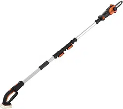
ASSEMBLING THE EXTENSION POLE TO THE
MACHINE (SEE FIG. F1)
Step 1: Loosen the pole saw assembly lever (17) as
shown in Fig F1. Align and insert the machine into
the extension pole.
Step 2: Press the pole saw assembly lever to tighten
the extension pole to the machine.
NOTE: Make sure the extension pole is locked
into position securely before operation.
REMOVING THE EXTENSION POLE (SEE FIG.
F2)
Step 1: Unlock the pole saw assembly lever (17) as
shown.
Step 2: Slide saw to disconnect the extension pole
with the saw while pressing both locking projections
(5) simultaneously.
ADJUSTING POLE LENGTH
The pole saw has a telescoping pole assembly that
will extend from 83 inch (fully retracted) to 110 inch
(fully extended).
Inner pole clamping level (18) is used to hold the
pole in position at any extended length.
1. To extend the pole, loosen the inner pole
clamping lever (18) as shown in Fig. G. Pole will
slide freely.
2. Pull inner pole section out to desired length of
extension.
NOTE: only extend pole to minimum length
required to reach limb that is being cut.
3. To lock pole in position, tighten clamping lever as
shown in Fig. G.
Loading ...
Loading ...
Loading ...