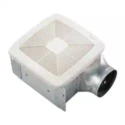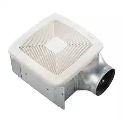
MODELS 770RLTK, 770RLTKC, 770RNLTK
Register this product at www.broan.com/register or www.nutone.com/reg-
ister. For Warranty Statement, or to order Service Parts: go to www.broan.
com and type the Model in the “Model Search” field at the top of the page.
Broan, 926 W. State Street, Hartford, WI 53027 800-558-1711 or
888-336-3948
1
Ventilation Fan with Decorative Light
READ AND SAVE THESE INSTRUCTIONS
WARNING
TO REDUCE THE RISK OF FIRE, ELECTRIC SHOCK, OR INJURY TO PER-
SONS, OBSERVE THE FOLLOWING:
1. Use this unit only in the manner intended by the manufacturer. If you
have questions, contact the manufacturer at the address or telephone
number listed in the warranty.
2. Before servicing or cleaning unit, switch power off at service panel
and lock the service disconnecting means to prevent power from be-
ing switched on accidentally. When the service disconnecting means
cannot be locked, securely fasten a prominent warning device, such
as a tag, to the service panel.
3. Installation work and electrical wiring must be done by a qualified
person(s) in accordance with all applicable codes and standards,
including fire-rated construction codes and standards.
4. Sufficient air is needed for proper combustion and exhausting of
gases through the flue (chimney) of fuel burning equipment to prevent
backdrafting. Follow the heating equipment manufacturer’s guideline
and safety standards such as those published by the National Fire
Protection Association (NFPA), and the American Society for Heating,
Refrigeration and Air Conditioning Engineers (ASHRAE), and the local
code authorities.
5. When cutting or drilling into wall or ceiling, do not damage electrical
wiring and other hidden utilities.
6. Ducted fans must always be vented to the outdoors.
7. Do not install in a bathtub or shower enclosure.
8. This unit must be grounded.
9. This unit is U.L. listed. Type I.C. inherently protected.
CAUTION
!
1. For general ventilating use only. Do not use to exhaust hazardous or
explosive materials and vapors.
2. This product is designed for installation in FLAT CEILINGS ONLY. Do
not mount this product in a wall.
3. The light fixture assembly must be mounted to the fan housing assembly
included with this product. Do not mount the light fixture assembly to
a wiring outlet box.
4. To avoid motor bearing damage and noisy and/or unbalanced impellers,
keep drywall spray, construction dust, etc. off power unit.
5. Please read specification label on product for further information and
requirements.
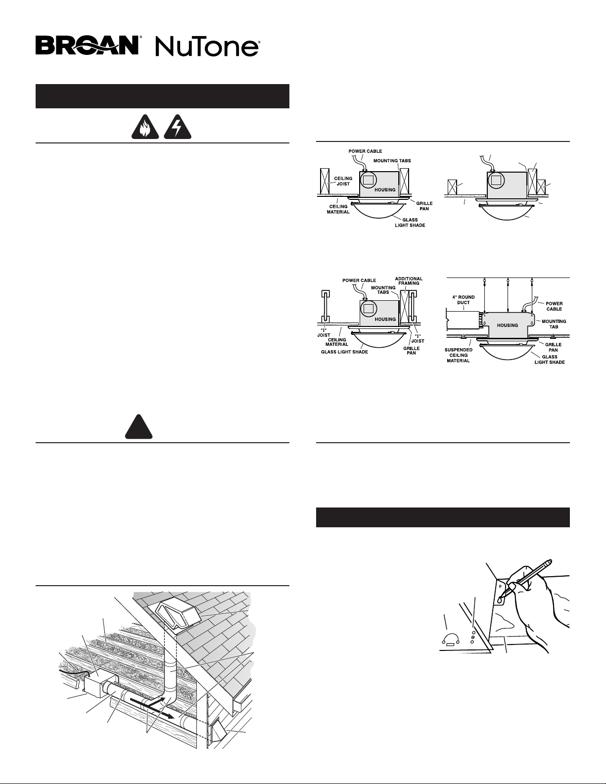
TYPICAL INSTALLATIONS
HOUSING MOUNTED
DIRECTLY TO JOIST
2x6 (or larger)
Discharge parallel to joists.
HOUSING
2 x 4
CEILING
JOIST or
TRUSS
MOUNTING
TABS
POWER CABLE
ADDITIONAL
FRAMING
2 x 4
CEILING
JOIST or
TRUSS
CEILING
MATERIAL
GRILLE
PAN
GLASS
LIGHT SHADE
HOUSING MOUNTED
TO 2x4 TRUSS
Requires additional framing
for mounting tabs.
Discharge parallel to joists.
HOUSING MOUNTED
TO “I” JOIST
Requires additional framing
for mounting tabs.
Discharge parallel to joists.
*
Additional framing must be a 2x6 (minimum height).
*
*
SUSPENDED CEILINGS
Housing hung with wires -
3-point mount.
PLAN THE INSTALLATION
ROOF CAP*
(with built-in
damper)
WALL CAP*
(with built-in
damper)
4-IN. ROUND
ELBOWS*
4-IN. ROUND
DUCT*
FAN
HOUSING
Seal gaps
around
housing.
Seal duct
joints with
tape.
Keep duct
runs short.
INSULATION
(Place around and
over fan housing.)
POWER
CABLE*
*Purchase
separately.
OR
INSTALL THE HOUSING
1. Choose the location for your fan in the ceiling. For best possible
performance, use the shortest possible duct run and a minimum
number of elbows.
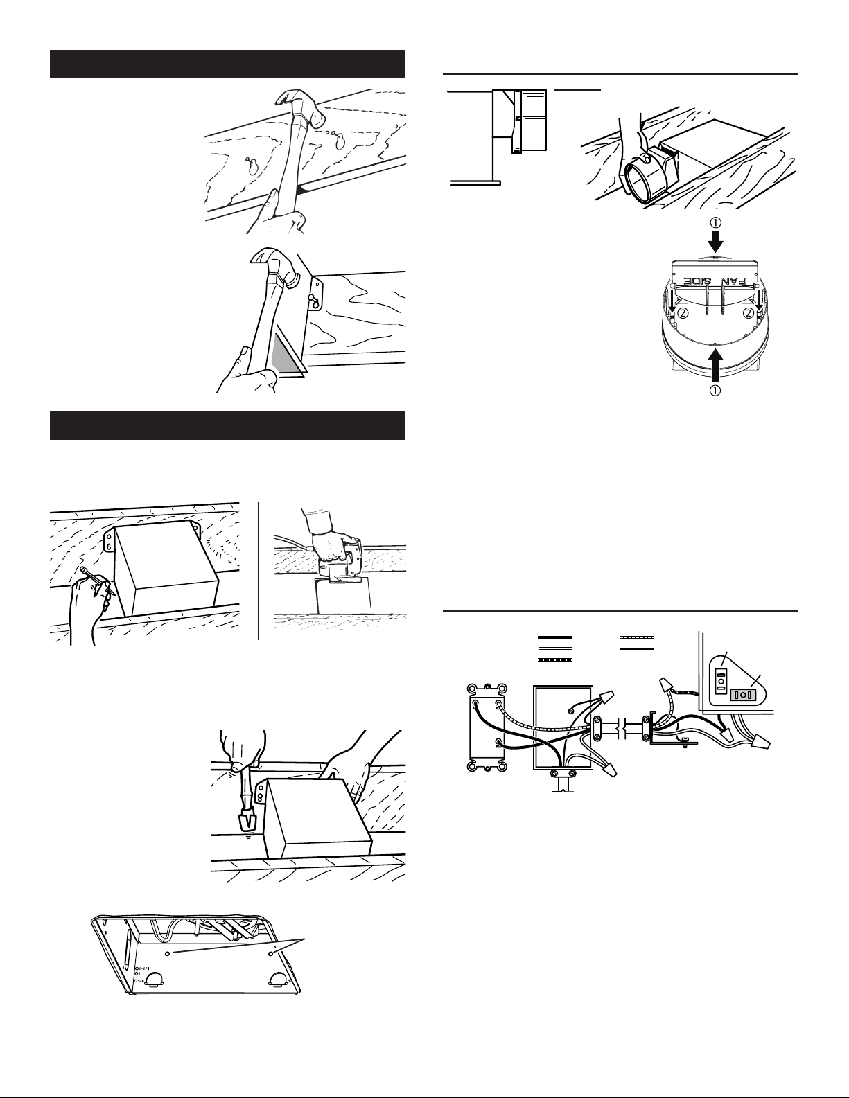
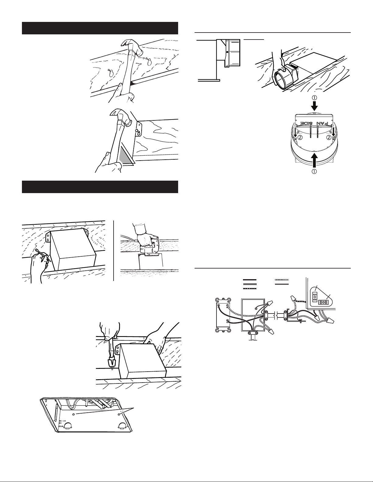
2. Position mounting brackets
against joist so that bottom
edge of housing will be flush
with finished ceiling.
Additional positioning
feature for 5/8”, 1”, &
1-1/4” thick ceiling material:
Holes in corners of housing
are labeled with various ceiling
material thicknesses. Position
housing so bottom edge of joist is visible through a matched
set of holes. The housing is now in the proper position for that
ceiling material thickness.
Additional positioning feature for 1/2” thick ceiling material:
Bend two tabs, on side of housing,
90
0
outward. Lift housing until
tabs contact underside of joist.
Mark the keyhole slot on both mounting brackets.
New Construction
5/8
1
1-1/4
TAB
HOLES
BOTTOM EDGE OF JOIST
- PLEASE NOTE -
THE FOLLOWING INSTALLATION ILLUSTRATIONS SHOW 2 X 6
JOISTS. IF YOU HAVE A TRUSS OR “I”-JOIST INSTALLATION, MOUNT
THE VENTILATOR TO THE ADDITIONAL FRAMING IN THE SAME MAN-
NER. (Additional framing must be a 2x6 (minimum height).
2
3. Set housing aside and
drive nails partially
into joist at the top of
both keyhole marks.
4. Hang housing from
nails and pound nails
tight. To ensure a
noise-free mount,
pound another nail
through the top hole of
each mounting tab.
Existing Construction
2. In attic, position mounting brackets against joist. Trace outline
of housing on ceiling material.
1. Choose the location for your fan/light in the ceiling. For best
possible performance, use the shortest possible duct run and a
minimum number of elbows.
3. Set housing aside and cut ceiling opening slightly larger than
marked.
4. Place housing in
opening so that its
bottom edge is flush
with finished ceiling.
Nail to joist through
keyhole on both
sides. To ensure a
noise-free installation,
drive another nail
through the top hole
of each mounting
bracket.
5. Additional mounting holes are provided for installations where
access from above is inconvenient or not possible. Nail or screw
housing directly to joists or framing.
ADDITIONAL
MOUNTING
HOLES
New Construction
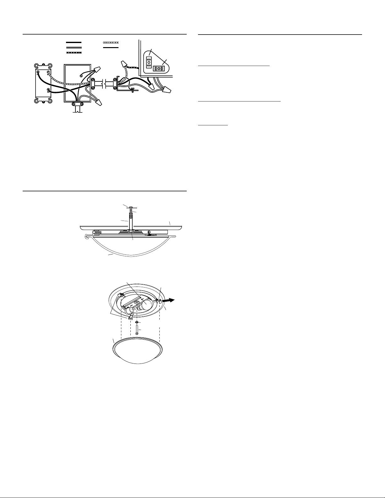
SWITCH BOX
LIGHT
FAN
DUAL CONTROL
(purchase separately)
WHITE
BLACK
RED
GROUND
(bare)
WIRING
PLATE
120 VAC
LINE IN
BLUE
BLACK
RECEPTACLE
(FAN)
WHITE
RECEPTACLE
(LIGHT)
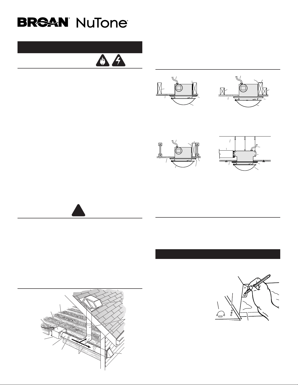
CONNECT THE WIRING
1. Wire unit following diagram above. Run electrical cable as direct
as possible to unit. Do not allow cable to touch sides or top of
unit after installation is complete.
INSTALL THE DUCTWORK
FLUSH
NOTE: The duct connector has a
counter-balanced damper flap. The
flap will be “open” approx. 1” when
duct connector is attached to hous-
ing. This design permits insulation
to be in direct contact with fan/
light housing per UL (Underwrit-
ers Laboratories) standards. The
slightest backdraft, however, will
close the damper flap, preventing air
from entering unit or finished space.
1. Snap the damper/duct connector onto housing. Make sure that
tabs on the connector lock into slots in housing. Top of damper/
duct connector should be flush with top of housing.
NOTE: Make sure damper flap is in place inside of duct connector.
If it is not:
Squeeze top and bottom of connector to
snap flap
back into place.
2. Connect 4” round duct to damper/duct connector and extend
duct to outside through a roof or wall cap. Check damper to make
sure that it opens freely. Tape all duct connections to make them
secure and air tight.

3
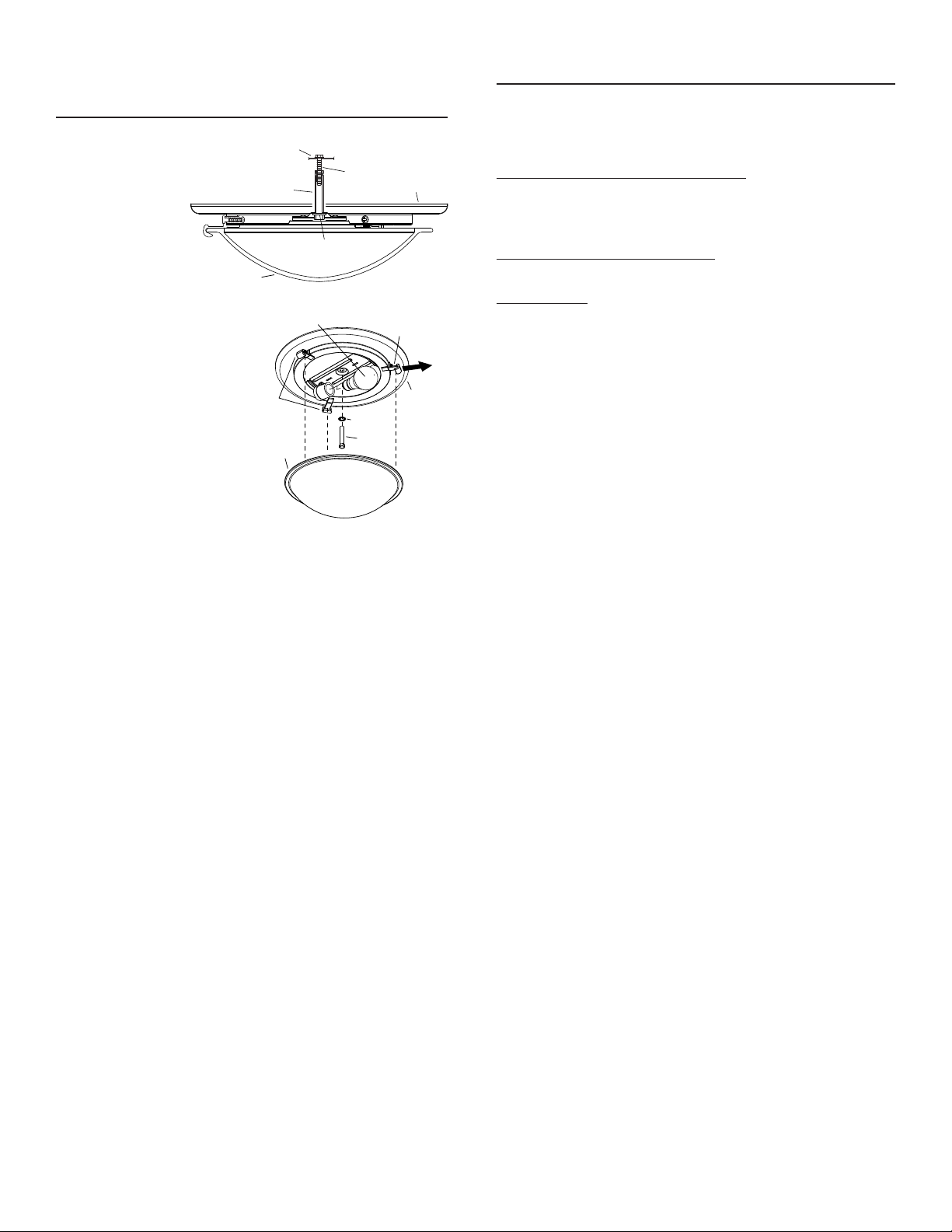
1. Locate the grille
pan over the
fan housing and
connect the wiring
harness plug into
white receptacle in
the fan housing.
2. Insert rod through
washer and
through center
hole of grille pan.
3. Thread rod onto grille
screw in housing,
until pan is tight
against ceiling. Do not
overtighten mounting
rod.
4. Install bulb. Use 60-watt
(maximum), E26 base
bulb.
5. Place rim of glass shade
into opening of two
stationary hooks. Pull
out the spring-loaded
hook and latch hook over
rim of glass shade.
6. Restore electrical power and check operation of the unit.
GRILLE
PAN
GRILLE
SCREW
WASHER
ROD
GLASS SHADE
MOTOR
MOUNTING
PLATE
GLASS
SHADE
GRILLE
PAN
ROD
WASHER
60 WATT MAX.
E26 BASE BULB
STATIONARY
HOOKS
SPRING-LOADED
HOOK
USE AND CARE
WARNING: DISCONNECT ELECTRICAL POWER SUPPLY AND LOCK OUT
SERVICE PANEL BEFORE CLEANING OR SERVICING THIS UNIT.
BULB REPLACEMENT
Remove glass shade. Replace bulbs as required. Replace glass shade.
Use 60-watt (maximum), E26 type, bulb or energy efficient equivalent.
MOTOR LUBRICATION
The motor is permanently lubricated. Do not oil or disassemble motor.
CLEANING
TO CLEAN GLASS SHADE AND GRILLE PAN:
Remove glass shade. Shade can be wiped clean with a mild detergent
solution or glass cleaner and dried with a soft cloth. Remove bulb. Grille
pan may be gently vacuumed and wiped clean with a soft cloth. Never
use abrasive cloth, steel wool pads or scouring powders on glass shade
or grille pan. METAL AND ELECTRICAL PARTS SHOULD NEVER BE IM-
MERSED IN WATER.
TO CLEAN FAN ASSEMBLY:
Remove grille pan and unplug fan assembly (black receptacle). Gently
vacuum fan, motor and interior of housing. METAL AND ELECTRICAL
PARTS SHOULD NEVER BE IMMERSED IN WATER.
1102078B
ATTACH THE GRILLE PAN
AND GLASS SHADE
MODÈLES 770RLTK, 770RLTKC, 770RNLTK
Pour enregistrer le produit, se rendre à fr.broan.ca/register.asp ou à
fr.nutone.ca/register.asp. Pour lire l’énoncé de garantie ou commander
des pièces, se rendre à fr.broan.ca et saisir le numéro de modèle dans le
champ Recherche d’un modèle au haut de la page.
Broan, 926 W. State Street, Hartford, WI 53027
800 558-1711 ou 888336-3948
4
Ventilateur luminaire décoratif
LIRE ET CONSERVER CES INSTRUCTIONS
AVERTISSEMENT
POUR RÉDUIRE LE RISQUE D’INCENDIE, D’ÉLECTROCUTION ET DE BLESSURE:
1. N’utiliser cet appareil que de la manière prévue par le fabricant. Pour
toute question, communiquer avec le fabricant à l’adresse ou au numéro
de téléphone indiqués dans la garantie.
2. Avant de procéder à l’entretien ou au nettoyage de l’appareil, couper le
courant au panneau d’alimentation et en verrouiller l’accès afin d’éviter
une remise en marche accidentelle. Si le panneau ne peut être verrouillé,
y fixer solidement un dispositif d’avertissement bien visible, p. ex. une
étiquette.
3. Les travaux d’installation et de raccordement électrique doivent être
effectués par une personne qualifiée, conformément aux codes et aux
normes de construction, y compris ceux concernant la protection contre
les incendies.
4. Un certain volume d’air est nécessaire aux appareils à combustible pour
assurer la bonne combustion et l’évacuation des gaz par le conduit
de fumée (cheminée) et ainsi éviter tout refoulement. Respecter les
recommandations du fabricant et les normes de sécurité, comme
celles publiées par la National Fire Protection Association (NFPA) et
l’American Society of Heating, Refrigerating and Air-Conditioning
Engineers (ASHRAE), ainsi que les codes applicables dans la région.
5. Lors de la découpe ou du perçage dans un mur ou un plafond,
prendre garde de ne pas endommager les fils électriques et les autres
installations qui pourraient être dissimulées.
6. Toujours évacuer à l’extérieur l’air des ventilateurs canalisés.
7. Ne pas installer au-dessus d’un bain ni au-dessus ou à l’intérieur d’une
douche.
8. Mettre à la terre cet appareil.
9. Cet appareil est homologué UL et de type IC à protection intrinsèque.
ATTENTION
!
1. Pour ventilation générale seulement. Ne pas utiliser pour évacuer des
matières ou des vapeurs dangereuses ou explosives.
2. N’installer que dans un PLAFOND PLAT. Ne pas installer au mur.
3. Fixer le luminaire sur le boîtier du ventilateur inclus et non sur une boîte
de sortie.
4. Pour éviter l’endommagement des paliers du moteur, la production de
bruits et le déséquilibre de la roue, tenir l’appareil à l’abri des poussières
de plâtre, de construction, etc.
5. Lire l’étiquette des caractéristiques sur le produit pour connaître d’autres
renseignements et exigences.
INSTALLATIONS TYPIQUES
CÂBLE D’ALIMENTATION
PLAQUES DE FIXATION
SOLIVE
BOÎTIER
REVÊTEMENT
DE PLAFOND
ABAT-JOUR
EN VERRE
CADRE DE
GRILLE
BOÎTIER FIXÉ À UNE SOLIVE
2 x 6 (ou plus grosse)
Évacuation parallèle aux
solives.
BOÎTIER
SOLIVE
OU
FERME
EN 2 x 4
PLAQUES DE
FIXATION
CÂBLE D’ALIMENTATION
CHARPENTE
ADDITIONNELLE
*
SOLIVE
OU
FERME
EN 2 x 4
REVÊTEMENT
DE PLAFOND
CADRE DE
GRILLE
ABAT-JOUR
EN VERRE
BOÎTIER FIXÉ À
UNE FERME EN 2 X 4
Charpente additionnelle nécessaire
pour les plaques de fixation.
Évacuation parallèle aux solives.
CÂBLE D’ALIMENTATION
PLAQUES DE
FIXATION
CHARPENTE
ADDITIONNELLE
*
CADRE DE
GRILLE
BOÎTIER
ABAT-JOUR EN VERRE
SOLIVE
EN I
SOLIVE
EN I
REVÊTEMENT
DE PLAFOND
BOÎTIER FIXÉ À
UNE SOLIVE EN I
Charpente additionnelle nécessaire
pour les plaques de fixation.
Évacuation parallèle aux solives.
*
La charpente additionnelle doit être en 2 x 6 (hauteur minimale).
PLAFOND SUSPENDU
Boîtier suspendu par trois
câbles.
REVÊTEMENT
DE PLAFOND
SUSPENDU
CÂBLE
D’ALIMENTATION
PLAQUE DE FIXATION
BOÎTIER
CONDUIT
ROND DE 4 po
ABAT-JOUR
EN VERRE
CADRE DE
GRILLE
PLANIFICATION DE
L’INSTALLATION
ÉVENT DE
TOITURE*
(avec clapet
intégré)
ÉVENT
MURAL*
(avec clapet
intégré)
COUDES
RONDS DE
4 po*
CONDUIT
ROND DE 4 po*
BOÎTIER DU
VENTILATEUR
Calfeutrer les
espaces autour
du boîtier.
Sceller
les joints
avec du
ruban.
Utiliser
autant que
possible un
tracé court.
ISOLANT
(Répartir autour et
au-dessus du boîtier
du ventilateur.)
CÂBLE
D’ALIMENTATION*
* Vendu séparément.
OU
INSTALLATION DU BOÎTIER
1. Choisir l’emplacement du ventilateur au plafond. Pour une
performance optimale, suivre le tracé de conduits le plus court
possible et utiliser un minimum de coudes.
2. Placer les plaques de
fixation contre la solive de
sorte que le bas du boîtier
soit affleurant avec le
revêtement de plafond.
Positionnement pour
revêtement de plafond
de 5/8, 1 et 11/4po
d’épaisseur:
Les coins du boîtier
comportent des trous
identifiés pour diverses épaisseurs de revêtement de plafond.
Positionner le boîtier de sorte que l’arête inférieure de la solive soit
visible dans les trous correspondant à l’épaisseur du revêtement.
Positionnement pour revêtement de plafond de 1/2po d’épaisseur:
Sur un côté du boîtier, plier les deux languettes à 90° vers l’extérieur.
Soulever le boîtier jusqu’à ce que les languettes touchent au bas de la
solive.
Marquer les encoches en trou de serrure des deux plaques de fixation.
Nouveau bâtiment
- IMPORTANT -
LES ILLUSTRATIONS QUI SUIVENT MONTRENT DES SOLIVES
EN 2X 6. POUR UNE INSTALLATION À UNE FERME OU À
UNE SOLIVE ENI, FIXER LE BOÎTIER DU VENTILATEUR À LA
CHARPENTE ADDITIONNELLE COMME SUR LES ILLUSTRATIONS.
(La charpente additionnelle doit être en 2 x 6 [hauteur minimale].)
5/8
1
1-1/4
LANGUETTE
TROUS
ARÊTE INFÉRIEURE DE LA SOLIVE
5
3. Mettre le boîtier
de côté et insérer
partiellement les
clous dans la solive
sur le haut des
deux marques des
encoches.
4. Accrocher le boîtier
aux clous, puis insérer
ceux-ci jusqu’au
bout. Insérer un clou
dans le trou du haut
des deux plaques de
fixation pour assurer
un fonctionnement
silencieux.
Bâtiment existant
2. Dans l’entretoit, placer les plaques de fixation contre la solive.
Tracer le contour du boîtier sur le revêtement de plafond.
1. Choisir l’emplacement du ventilateur luminaire au plafond. Pour
une performance optimale, suivre le tracé de conduits le plus
court possible et utiliser un minimum de coudes.
3. Mettre le boîtier de côté et couper une ouverture dans le
revêtement, légèrement plus grande que le contour tracé.
4. Placer le boîtier dans
l’ouverture de sorte que
le bas soit affleurant à
la surface inférieure du
revêtement de plafond.
Clouer le boîtier à la
solive par les deux
encoches en trou de
serrure. Insérer un clou
dans le trou du haut
des deux plaques de
fixation pour assurer
un fonctionnement
silencieux.
5. Le boîtier comporte des trous de fixation additionnels pour
les installations où l’accès par le dessus est difficile, voire
impossible. Clouer ou visser le boîtier directement à la solive
ou à la charpente.
TROUS DE
FIXATION
ADDITIONNELS
Nouveau bâtiment (suite)
BOÎTE DE COMMUTATION
LUMINAIRE
VENTILATEUR
COMMANDE DOUBLE
(vendue séparément)
BLANC
NOIR
ROUGE
MISE À LA
TERRE
(DÉNUDÉ)
PLAQUE DE
CÂBLAGE
LIGNE
120 V CA
BLEU
PRISE NOIRE
(VENTILATEUR)
PRISE
BLANCHE
(LUMINAIRE)
CONNEXION DU CÂBLAGE
1. Brancher les fils comme l’indique le schéma de câblage
ci-dessus. Passer le câble d’alimentation de l’appareil par le
tracé le plus court. S’assurer que les câbles ne touchent pas
les côtés ni le dessus de l’appareil après l’installation.
INSTALLATION DES CONDUITS
AFFLEURANT
N.B.: Le raccord de conduit est doté
d’un clapet à contrepoids qui s’ouvre
d’environ 2,5 cm lorsque le raccord
est fixé au boîtier. Cette configuration
permet à l’isolant d’être en contact
direct avec le boîtier du ventilateur
luminaire conformément aux
normes d’Underwriters Laboratories
(UL). Le moindre courant en sens
inverse ferme le clapet, empêchant
l’air d’entrer dans l’appareil ou dans
la pièce.
1. Installer le raccord de conduit avec clapet sur le boîtier. Vérifier
que les languettes du raccord sont bien fixées dans les fentes
du boîtier. Le dessus du raccord doit être affleurant à celui du
boîtier.
N.B.: Vérifier que le clapet est en place dans le raccord. Autrement,
1)appuyer sur le haut et le bas du raccord pour que 2)le clapet se
referme correctement.
2. Raccorder des conduits ronds de 4po au raccord jusqu’à
l’évent mural ou l’évent de toiture. Vérifier que le clapet s’ouvre
facilement. Appliquer du ruban adhésif sur toutes les jonctions
des conduits pour les fixer en place et assurer l’étanchéité.
6
1. Placer le cadre de
grille sur le boîtier
et brancher le
câble sur la prise
blanche du boîtier.
2. Insérer la tige
dans la rondelle
et dans le trou
central du cadre.
3. Visser la tige sur
la vis de la grille dans le
boîtier jusqu’à ce que le
cadre soit bien appuyé
au plafond. Ne pas trop
serrer.
4. Installer une ampoule à
culot E26 d’au plus 60W.
5. Placer l’abat-jour en verre
dans les deux crochets
fixes. Tirer sur le crochet
à ressort, insérer
l’abat-jour et relâcher le
crochet à ressort de sorte
que l’abat-jour tienne
bien en place.
6. Rétablir le courant et vérifier le fonctionnement de l’appareil.
CADRE DE
GRILLE
VIS DE LA
GRILLE
RONDELLE
TIGE
ABAT-JOUR
EN VERRE
PLAQUE DE
FIXATION
DU MOTEUR
ABAT-JOUR
EN VERRE
CADRE DE
GRILLE
TIGE
RONDELLE
AMPOULE À CULOT
E26 DE 60 W MAX.
CROCHETS
FIXES
CROCHET À
RESSORT
UTILISATION ET ENTRETIEN
AVERTISSEMENT : AVANT DE PROCÉDER À L’ENTRETIEN OU AU
NETTOYAGE DE L’APPAREIL, COUPER LE COURANT AU PANNEAU
D’ALIMENTATION ET EN VERROUILLER L’ACCÈS.
REMPLACEMENT DE L’AMPOULE
Retirer l’abat-jour en verre, remplacer l’ampoule et replacer l’abat-jour.
Utiliser une ampoule à culot E26 d’au plus 60 W ou l’équivalent en version
écoénergétique.
LUBRIFICATION DU MOTEUR
Le moteur est lubrifié à vie. Ne pas l’huiler ni le démonter.
NETTOYAGE
ABAT-JOUR EN VERRE ET CADRE DE GRILLE
Retirer l’abat-jour en verre et le nettoyer avec une solution de détergent
doux ou un nettoyant pour vitres et un linge doux. Retirer l’ampoule.
Passer doucement l’aspirateur sur le cadre de grille ou l’épousseter avec
un linge doux. Ne jamais utiliser de linge abrasif, de laines d’acier ou de
poudre à récurer sur l’abat-jour en verre ou le cadre de grille. NE JAMAIS
IMMERGER LES PIÈCES MÉTALLIQUES OU ÉLECTRIQUES DANS L’EAU.
VENTILATEUR
Retirer le cadre de grille et débrancher le ventilateur (prise noire). Passer
doucement l’aspirateur sur le ventilateur, sur le moteur et dans le boîtier.
NE JAMAIS IMMERGER LES PIÈCES MÉTALLIQUES OU ÉLECTRIQUES
DANS L’EAU.
1102078B
INSTALLATION DU CADRE DE
GRILLE ET DE L’ABAT-JOUR
7
Ventilador Decorativa con la luz
ADVERTENCIA
PARA REDUCIR EL RIESGO DE INCENDIO, DESCARGA ELÉCTRICA O LESIONES
PERSONALES, OBSERVE LO SIGUIENTE:
1. Utilice esta unidad solamente de acuerdo con las instrucciones del fabricante. Si
tiene preguntas comuníquese con el fabricante a la dirección o al número telefónico
que se indica en la garantía.
2. Antes de dar servicio o limpiar la unidad, interrumpa el suministro de energía
en el panel de servicio y bloquee los dispositivos de desconexión para evitar
la reinstalación accidental de la energía. Cuando no se puedan bloquear los
dispositivos de desconexión, fije seguramente en el panel de servicio un medio
de advertencia que sea visible, como por ejemplo una etiqueta.
3. Una persona o personas calificadas deben realizar el trabajo de instalación y el
cableado eléctrico, de acuerdo con todos los códigos y normas aplicables, inclusive
los códigos y normas de construcción para evitar incendios.
4. Se necesita suficiente aire para que se realice la combustión y la descarga de
gases adecuadas a través de la chimenea del equipo para quemar combustible a
fin de evitar las corrientes de inversión. Observe los lineamientos del fabricante
del equipo de calefacción y las normas de seguridad, como por ejemplo las
publicadas por la Asociación Nacional de Protección contra Incendios (National
Fire Protection Association: NFPA), y la Sociedad Americana de Ingenieros en
Calefacción, Refrigeración y Sistemas de Acondicionamiento de Aire (American
Society for Heating, Refrigeration and Air Conditioning Engineers: ASHRAE), y los
códigos locales.
5. Cuando corte o perfore la pared o el cielo raso, tenga cuidado de no dañar el
cableado eléctrico ni otras conexiones de servicios que se encuentren ocultas.
6. Los ventiladores con conductos siempre deben tener salida hacia el exterior.
7. No lo instale en un recinto de ducha o bañera.
8. Esta unidad se debe conectar a tierra.
9. Esta unidad está incluida en la lista de U.L. Tipo I.C. proteger inherente.
PRECAUCIÓN
!
1. Esta unidad debe usarse solamente para ventilación general. No la utilice para la
descarga de materiales ni vapores peligrosos o explosivos.
2. Este producto está diseñado SOLAMENTE PARA INSTALARSE EN EL CIELO RASO.
No monte este producto en la pared.
3. El conjunto de la luz se debe montar al montaje de la cubierta del ventilador incluido
con este producto. No monte el conjunto de la luz a una caja del enchufe del
cableado.
4. Para evitar causar daño a los cojinetes del motor y pistones impulsores ruidosos y/o
no balanceados, mantenga los aerosoles para pirca, el polvo de construcción, etc.
lejos del motor.
5. Por favor consulte la información y los requerimientos adicionales contenidos en la
etiqueta de especificaciones que se encuentra en el producto.
LEA Y CONSERVE ESTAS INSTRUCCIONES
INSTALACIONES TÍPICAS
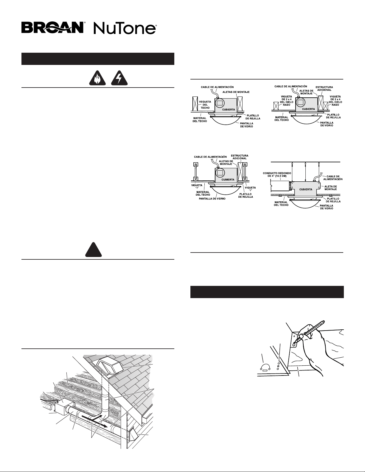
CUBIERTA MONTADA
DIRECTAMENTE EN LA VIGUETA
2x6 (o más grande).
Descarga paralela a las viguetas.
CUBIERTA MONTADA
EN UNA VIGA DE 2x4
Se requiere una estructura
adicional para las aletas de
montaje. Descarga paralela a
las viguetas.
*
La estructura adicional debe ser un tramo de 2x6 (altura mínima).
CUBIERTA MONTADA
EN UNA VIGUETA “I”
Se requiere una estructura
adicional para las aletas de
montaje. Descarga paralela a
las viguetas.
*
*
TECHOS SUSPENDIDOS
Cubierta montada con cables.
Montaje de tres puntos.
PLANIFICACIÓN DE LA INSTALACIÓN
TAPA DE
TECHO*
(con
amortiguador
integral)
TAPA DE
PARED*
(con amortiguador
integral)
CODO REDONDO
DE 4 PULG.*
CONDUCTO REDONDO
DE 4 PULG. *
CUBIERTA DE
VENTILADOR
Selle los
huecos alrededor
de la cubierta.
Sellar las juntas
con cinta.
Mantenga
corre
conducto
corto.
AISLAMIENTO
(Puede ser colocado
alrededor y sobre de la
cubierta del ventilador.)
*Se compran
por separado.
O
CABLE DE
ALIMENTACIÓN*
INSTALACIÓN DE LA CUBIERTA
Construcción nueva
5/8
1
1-1/4
ALETA
OROFICIOS
BORDE INFERIOR DE LA VIGUETA
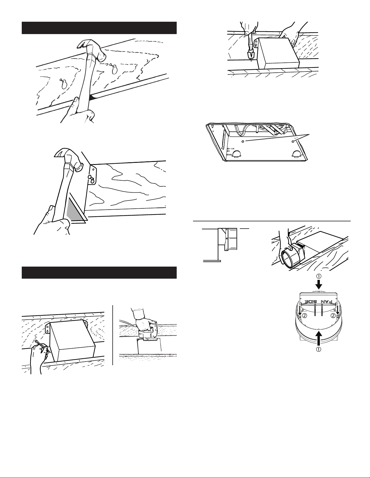
2. Coloque las abrazaderas
de montaje contra la
vigueta, de manera que
el borde inferior de la
cubierta quede al ras del
cielo raso terminado.
Característica adicional
para la colocación en
material de cielo raso de
5/8” (1.6 cm), 1” (2.5 cm)
y 1 ¼” (3.2 cm):
Los orificios que se
encuentran en las esquinas de la cubierta están marcados con varios
espesores del material del cielo raso. Coloque la cubierta de manera que
el borde inferior de la vigueta sea visible a través del conjunto de orificios
que coinciden. Ahora la cubierta se encuentra en la posición adecuada
para ese espesor del material del cielo raso.
Característica adicional para la colocación en material de cielo raso
de ½” (1.3 cm):
Doble a 90° y hacia afuera las dos aletas que se encuentran a los
costados de la cubierta. Levante la cubierta hasta que las aletas entren
en contacto con la cara inferior de la vigueta.
Marque el orificio con forma de cerradura de ambas abrazaderas de montaje.
- POR FAVOR NOTE -
LAS SIGUIENTES ILUSTRACIONES DE LA INSTALACIÓN MUESTRAN VIGUETAS
DE 2 X 6. SI LA INSTALACIÓN ES EN UNA VIGA O EN UNA VIGUETA EN “I”, MONTE
EL VENTILADOR EN LA ESTRUCTURA ADICIONAL DE LA MISMA MANERA. (La
estructura adicional debe ser un tramo de 2x6 (altura mínima).
1. Seleccione la ubicación del ventilador con lámpara en el cielo raso. Para
obtener el mejor rendimiento posible, utilice un tramo de conductos lo
más corto posible y un número mínimo de codos.
Registre este producto en www.broan.com/register o www.nutone.com/
register. Para Declaración de garantía, o para pedir piezas de servicio: vaya a
www.broan.com y escriba el modelo en el campo “Model Search” en la parte
superior de la página.
Broan, 926 W. State Street, Hartford, WI 53027 800-558-1711 o 888-336-3948
MODELOS 770RLTK, 770RLTKC, 770RNLTK
8
3. Coloque la cubierta a un lado e introduzca parcialmente los clavos en
la vigueta, en la parte superior de ambas marcas de los orificios en
forma de cerradura.
4. Suspenda la cubierta con los clavos e introduzca los clavos completa-
mente. Para asegurar un montaje sin ruido, coloque otro clavo en el
orificio superior de cada aleta de montaje.
Construcción nueva
Construcción existente
2. En el entretecho, coloque las abrazaderas de montaje contra la vigueta.
Trace el perímetro de la cubierta en el material del techo.
1. Seleccione la ubicación del ventilador con lámpara en el cielo raso. Para
obtener el mejor rendimiento posible, utilice un tramo de conductos lo
más corto posible y un número mínimo de codos.
3. Coloque la cubierta a un lado y haga una abertura en el techo ligeramente
más grande que el perímetro marcado.
4. Coloque la cubierta en la abertura de manera que su borde inferior quede
al ras del cielo raso terminado. Clave la cubierta en la vigueta a través
del orificio en forma de cerradura, en ambos lados. Para asegurar un
montaje sin ruido, coloque otro clavo en el orificio superior de cada
aleta de montaje.
5. En la cubierta se pueden encontrar orificios de montaje adicionales para
aquellas instalaciones en las que es inconveniente o imposible el acceso
desde arriba. Clave o atornille la cubierta directamente en las viguetas
o el armazón.
ORIFICIOS
DE MONTAJE
ADICIONALES
INSTALACIÓN DEL SISTEMA
DE CONDUCTOS
AL RAS
NOTA: El conector del conducto tiene una
aleta compensadora para el regulador de tiro
La aleta estará “abierta” aproximadamente 1”
(2.5 cm) cuando el conector del conducto se
sujete a la cubierta. Este diseño permite que
el material de aislamiento esté en contacto
directo con la cubierta del ventilador con
lámpara de acuerdo con las normas de UL
(Underwriters Laboratories). Sin embargo, la
más ligera corriente invertida cerrará la aleta
del regulador de tiro, evitando así la entrada de
aire a la unidad o al espacio terminado.
1. Conecte a presión el conector del regulador de tiro/conducto en la
cubierta. Asegúrese de que las aletas del conector queden fijas en las
ranuras de la cubierta. La parte superior del conector del regulador de
tiro/conducto debe quedar al ras de la parte superior de la cubierta.
NOTA: Asegúrese de que la tapa del regulador de tiro esté colocada
dentro del conector del conducto. Si no lo está:
Comprima la parte
superior e inferior del conector para
volver a colocar la tapa en su
lugar.
2. Conecte el conducto redondo de 4” (10.2 cm) en el conector del
regulador de tiro/conducto y extienda el conducto hasta el exterior
a través de una tapa de techo o de pared. Revise el regulador de tiro
para asegurarse de que abre libremente. Coloque cinta en todas las
conexiones de los conductos para asegurarlas y hacerlas herméticas.
9
CONEXIÓN ELÉCTRICA
CAJA DEL CONMUTADOR
LAMP.
VENT.
CONTROL DOBLE
(se vende por separado)
BLANCO
NEGRO
ROJO
TIERRA
(desnudo)
PLACA DE
CONEXIONES
LÍNEA DE ENTRADA
DE 120 VCA
AZUL
RECEPTÁCULO
BLANCO (LAMP.)
RECEPTÁCULO
NEGRO (VENT.)
ARME EL TACHO DE REJILLA
Y LA COTINILLA DE VIDRIO
1. Conecte la unidad de acuerdo con este diagrama. Extienda el cable
eléctrico a la unidad tan directamente como sea posible. No permita
que el cable toque los costados ni la parte superior de la unidad
después de que la instalación esté terminada.
1. Coloque la platillo
de la rejilla sobre la
caja del ventilador y
conecte el enchufe
del cableado
preformado en el
receptáculo blanco
de la caja del
ventilador.
2. Inserte la varilla a
través de la arandela
y a través del orificio
central del platillo de
la rejilla.
3. Enrosque la varilla en
el tornillo de la parrilla
de la caja, hasta que la
platillo quede ajustada
contra el cielo raso.
No apriete la varilla
demasiado.
4. Instale la bombilla.
Utilice una bombilla de
base E26 de 60 vatios
(máximo).
5. Coloque el borde de
la pantalla de vidrio
en la abertura de los
dos ganchos inmóviles. Saque el gancho por resorte y trabe el gancho
sobre el borde de la pantalla de vidrio.
6. Restaure la energía eléctrica y verifique la operación de la unidad.
PLACA DE
SUPPORTE
DEL MOTOR
PLATILLO
DE LA REJILLA
TORNILLO
DE LA
REJILLA
ARANDELA
PANTALLA
DE VIDRIO
VARILLA
GANCHOS
INMÓVILES
GANCHO
POR RESORTE
FOCO
DE BASE E26
60 WATTS MÁX.
VARILLA
PANTALLA
DE VIDRIO
PLATILLO DE
LA REJILLA
ARANDELA
USO Y CUIDADO
ADVERTENCIA: DESCONECTE LA CORRIENTE ELECTRICA Y BLOQUEE EL
TABLERO DE SERVICIO ANTES DE LIMPIAR OR REPARAR LA UNIDAD.
REEMPLAZO DEL FOCO
Quite la pantalla de vidrio. Reemplace los bulbos como necesarios.
Utilice el bulbo tipo de E26, 60 vatios máximo o de eficiencia energética
equivalente.
LUBRICACIÓN DEL MOTOR
El motor lleva lubricación permanente. No lo enaceite o desarme.
LIMPIEZA
PARA LIMPIAR EL LENTE Y LA REJILLA:
Saque la tuerca de remate y sombrerete y quite la pantalla. La pantalla puede
limpiarse con una ligera solución detergente o limpia vidrio y secarse con
un trapo suave. Saque el foco y desconecte el enchufe del portalámpara. El
tacho de rejilla puede limpiarse cuidadosamente con la aspiradora de polvo
y secarse con un trapo suave. Nunca unse telas abrasivas o estropajo de
acero o polvos para frejar cuando limpie la cortinilla o el tacho de rejilla. LAS
PIEZAS METALICAS Y ELECTRICAS NUNCA DEBEN SUMERGIRSE EN AGUA.
PARA LIMPIAR EL VENTILADOR:
Saque la placa de la rejilla y desenchufe el ventilador (receptáculo NEGRO).
Con la aspiradora limpie cuidadosamente el ventilador, motor, e interior de
la caja. LAS PIEZAS METALICAS Y ELECTRICAS NUNCA DEBEN SUMERGIR
EN AGUA.
1102078B

10

11

12
1102078B