Loading ...
Loading ...
Loading ...

4
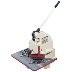
Specifications: HN-16T
Stock Number................................................................................................................................ 756016
Cutting Capacity ......................................................................................................................... 16 Gauge
Piercing Capacity........................................................................................................................ 18 Gauge
Maximum Notch .............................................................................................................................. 6” x 6”
Stroke.................................................................................................................................................. 3/4"
Overall Dimensions (LxWxH) ............................................................................................... 24” x 21” x 26”
Net Weight .................................................................................................................................... 165 lbs.
Uncrating and Clean-Up
1. Remove the HN-16T from the crate.
2. Carefully clean all rust protected surfaces
with a mild solvent or kerosene and a soft
rag. Do not use lacquer thinner, paint
thinner, or gasoline. These will damage
painted surfaces.
3. Lubricate all moving parts of the machine
with light grease, or heavy oil.
4. Carefully move the machine to a well lighted
area and attach to a solid, level work bench.
Notcher Setup
Use a machinist’s level and shims if the notcher
is not level. The notcher has been adjusted at
the factory for proper use of capacity material.
During shipment of this unit the machine may
have come out of alignment.
Blade Adjustment
The (#) in the text refers to the breakdown.
1. Remove the table (8-01) and position the
ram (3-01) to its lowest position.
2. Slightly loosen socket head cap screws (5-
03).
3. Use the set screw (7-02) to adjust the
positioning block (7-01). The blade gap
should be approximately 0.002”. As a
general rule the blade gap should be
approximately 6% of stock thickness.
4. Tighten screws (5-03).
Blades
The upper blades (4-01 & 4-02) are factory set
for “splay” cutting. This method provides that
the cut begins at the outside of the material.
The capacity at this setting is 16 gauge. The
notcher is also capable of piercing. To
accomplish this, interchange upper blades end
for end so that the cut begins at the apex or
corner of inside out. Align blades at the point
flush and tighten screws. In the piercing
capacity the notcher’s capacity is reduced to 18
gauge mild steel.
Depth of Cut
Adjust set screw (3-08) to stop the ram at a
desired depth and tighten hex nut (3-07).
Ram Brake
The set screw (3-04) acts as a drag on the ram
so that the blade does not free fall. The screw
should be checked and adjusted as needed.
Opening Throat
The notcher’s throat can be opened by removing
hex socket cap screw (1-08). This will allow
squaring, or shearing. Always replace screw
when notching.
Slitting
Remove the upper left blade (4-02) and mount
the right blade in the splay position, and open
the throat. Always replace screw (1-08) when
notching.
Ram Adjustment
Normal wear on the ram (3-01) may require
adjustment. Loosen set screws (3-04) and
evenly tighten the hex socket cap screws (3-03)
until the ram is snug. Tighten set screws from
side to side until the ram has a proper fit.
Lubricate the ways.
Lubrication
Lubricate the ways weekly, and lightly oil
machined surfaces to prevent rust. Lubricate
daily oil pinholes that are located on the
eccentric bushing (2-02), and top of the ram (3-
01).
Loading ...
Loading ...
Loading ...