

20V BRUSHLESS 125mm/115mm
ANGLE
GRINDER
98104
ORIGINAL LANGUAGE
These instructions accompanying the product are the original instructions. This document is part of the product,
keep it for the life of the product passing it on to any subsequent holder of the product. Read all these instructions
before assembling, operating or maintaining this product.
This manual has been compiled by Draper Tools describing the purpose for which the product has been designed,
and contains all the necessary information to ensure its correct and safe use. By following all the general safety
instructions contained in this manual, it will ensure both product and operator safety, together with longer life of the
product itself.
All photographs and drawings in this manual are supplied by Draper Tools to help illustrate the operation of the
product.
Whilst every effort has been made to ensure the accuracy of information contained in this manual, the Draper
Tools policy of continuous improvement determines the right to make modications without prior warning.
1. INTRODUCTION
1.1 SCOPE
This hand held power tool uses abrasive discs to grind/
cut metals or masonry.
As part of our core range it is suitable for enthusiasts
and tradespeople alike, any application other than that it
was intended for, is considered misuse.
This product is not a toy and must not be used by
children or any person with reduced physical, sensory or
mental capabilities or lack of experience and knowledge,
or people unfamiliar with these instructions.
Local regulations may restrict the age of the operator.
1.2 UNDERSTANDING THIS MANUALS
SAFETY CONTENT:
Warning! – Information that draws attention to the
risk of injury or death.
Caution! – Information that draws attention to the risk of
damage to the product or surroundings.
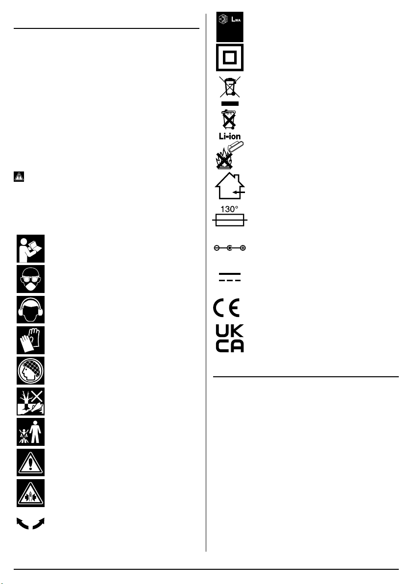
1.3 EXPLANATION OF SYMBOLS
Read the instruction manual.
Wear face mask and safety glasses.
Wear ear defenders.
Wear protective gloves.
Long hair must be tied back.
Do not abandon into the environment.
Keep out of the reach of children.
Warning!
Warning! Risk of crushing.
Direction of rotation.
dB
99
Continuous A-Weighted Sound
Pressure Level.
Class II construction
(Double insulated).
WEEE –
Waste Electrical & Electronic Equipment.
Do not dispose of Waste Electrical & Electronic
Equipment in with domestic rubbish.
Lithium-ion product.
Do not incinerate or throw
onto re.
For indoor use only.
Do not expose to rain.
Fuse protective device.
Polarity indication.
Rated voltage.
European conformity.
UK Conformity Assessed.
2. SPECIFICATION
2.1 SPECIFICATION
Stock No. .............................................................. 98104
Part No. .............................................................. D20AG
Rated voltage .............................................................20V
Revolutions per minute (no load): ................. 8,500r/min
Disc Diameter: ........................................ 125mm/115mm
Spindle thread: ......................................................... M14
Sound pressure level (LpA): .............................. 88dB(A)
Sound power level (LWA): .................................. 99dB(A)
Uncertainty (K): ................................................... 3dB(A)
Vibration level Main handle: .....AG=3.7m/s2, K=1.5m/s2
Weight (machine only):......................................... 1.46kg
–
2
–

–
3
–
3. HEALTH AND SAFETY
INFORMATION
3.1 GENERAL SAFETY
INSTRUCTIONS FOR POWER TOOL
USE
Warning! Read all safety warnings, instructions,
illustrations and specications provided with this
power tool. Failure to follow all instructions listed below
may result in electric shock, re and/or serious injury.
Save all warnings and instructions for future
reference.
The term “power tools” in the warnings refers to your
mains-operated (corded) power tool or battery-operated
(cordless) power tool.
1) Work area safety
a) Keep work area clean and well lit. Cluttered
or dark areas invite accidents.
b) Do not operate power tools in explosive
atmospheres, such as in the presence of
ammable liquids, gases or dust. Power
tools create sparks which may ignite the dust
or fumes.
c) Keep children and bystanders away while
operating a power tool. Distractions can
cause you to lose control.
2) Electrical safety
a) Power tool plugs must match the outlet.
Never modify the plug in any way. Do not
use any adapter plugs with earthed
(grounded) power tools. Unmodied plugs
and matching outlets will reduce risk of
electric shock.
b) Avoid body contact with earthed or
grounded surfaces, such as pipes,
radiators, ranges and refrigerators. There
is an increased risk of electric shock if your
body is earthed or grounded.
c) Do not expose power tools to rain or wet
conditions. Water entering a power tool will
increase the risk of electric shock.
d) Do not abuse the cord. Never use the cord
for carrying, pulling or unplugging the
power tool. Keep cord away from heat, oil,
sharp edges or moving parts. Damaged or
entangled cords increase the risk of electric
shock.
e) When operating a power tool outdoors,
use an extension cord suitable for outdoor
use. Use of a cord suitable for outdoor use
reduces the risk of electric shock.
f) If operating a power tool in a damp
location is unavoidable, use a residual
current device (RCD) protected supply.
Use of an RCD reduces the risk of electric
shock.
3) Personal safety
a) Stay alert, watch what you are doing and
use common sense when operating a
power tool. Do not use a power tool while
you are tired or under the inuence of
drugs, alcohol or medication. A moment of
inattention while operating power tools may
result in serious personal injury.
b) Use personal protective equipment Always
wear eye protection. Protective equipment
such as a dust mask, non-skid safety shoes,
hard hat or hearing protection use for
appropriate conditions will reduce personal
injuries.
c) Prevent unintentional starting. Ensure the
switch is in the off-position before
connecting to power source and/or battery
pack, picking up or carrying the tool.
Carrying power tools with your nger on the
switch or energising power tools that have the
switch on invites accidents.
d) Remove any adjusting key or wrench
before turning the power tool on. A wrench
or a key left attached to a rotating part of the
power tool may result in personal injury.
e) Do not overreach. Keep proper footing and
balance at all times. This enables better
control of the power tool in unexpected
situations.
f) Dress properly. Do not wear loose clothing
or jewellery. Keep your hair and clothing
away from moving parts. Loose clothes,
jewellery or long hair can be caught in moving
parts.
g) If devices are provided for the connection
of dust extraction and collection facilities,
ensure these are connected and properly
used. Use of dust collection can reduce
dust-related hazards.
h) Do not let familiarity gained from frequent
use of tools allow you to become
complacent and ignore tool safety
principles. A careless action can cause
severe injury within a fraction of a second.
4) Power tool use and care
a) Do not force the power tool. Use the
correct power tool for your application.
The correct power tool will do the job better
and safer at the rate for which it was
designed.
b) Do not use the power tool if the switch
does not turn it on and off. Any power tool
that cannot be controlled with the switch is
dangerous and must be repaired.
c) Disconnect the plug from the power
source and/or remove the battery pack, if
detachable, from the power tool before
making any adjustments, changing

–
4
–
accessories, or storing power tools. Such
preventive safety measures reduce the risk of
starting the power tool accidentally.
d) Store idle power tools out of the reach of
children and do not allow persons
unfamiliar with the power tool or these
instructions to operate the power tool.
Power tools are dangerous in the hands of
untrained users.
e) Maintain power tools and accessories.
Check for misalignment or binding of
moving parts, breakage of parts and any
other condition that may affect the power
tool’s operation. If damaged, have the
power tool repaired before use. Many
accidents are caused by poorly maintained
power tools.
f) Keep cutting tools sharp and clean.
Properly maintained cutting tools with sharp
cutting edges are less likely to bind and are
easier to control.
g) Use the power tool, accessories and tool
bits etc. in accordance with these
instructions, taking into account the
working conditions and the work to be
performed. Use of the power tool for
operations different from those intended could
result in a hazardous situation.
h) Keep handles and grasping surfaces dry,
clean and free from oil and grease. Slippery
handles and grasping surfaces do not allow
for safe handling and control of the tool in
unexpected situations.
5) Service
a) Have your power tool serviced by a
qualied repair person using only identical
replacements parts. This will ensure that the
safety of the power tool is maintained.
3.2 ADDITIONAL SAFETY
INSTRUCTIONS FOR GRINDERS
Warning!
Safety instructions for all operations
Safety warnings common for grinding:
a) This power tool is intended to function as
a grinder. Read all safety warnings,
instructions, illustrations and
specications provided with this power
tool. Failure to follow all instructions listed
below may result in electric shock, re and/or
serious injury.
b) Operations such as polishing, sanding,
wire brushing or cutting-off are not
recommended to be performed with this
power tool. Operations for which the power
tool was not designed may create a hazard
and cause personal injury.
c) Do not use accessories which are not
specically designed and recommended
by the tool manufacturer. Just because the
accessory can be attached to your power tool,
it does not assure safe operation.
d) The rated speed of the grinding
accessories must be at least equal to the
maximum speed marked on the power
tool. Grinding accessories running faster than
their rated speed can break and y apart.
e) The outside diameter and the thickness of
your accessory must be within the
capacity rating of your power tool.
Incorrectly sized accessories cannot be
adequately controlled.
f) Threaded mounting of accessories must
match the grinder spindle thread. For
accessories mounted by anges, the
arbour hole of the accessory must t the
locating diameter of the ange. Accessories
that do not match the mounting hardware of
the power tool will run out of balance, vibrate
excessively and may cause loss of control.
g) Do not use a damaged accessory. Before
each use inspect the accessory such as
abrasive wheels for chips and cracks,
sanding drum for cracks, tear or excess
wear, wire brush for loose or cracked
wires. If power tool or accessory is
dropped, inspect for damage or install an
undamaged accessory. After inspecting
and installing an accessory, position
yourself and bystanders away from the
plane of the rotating accessory and run the
power tool at maximum no-load speed for
one minute. Damaged accessories will
normally break apart during this test time.
h) Wear personal protective equipment.
Depending on application, use face shield,
safety goggles or safety glasses. As
appropriate, wear dust mask, hearing
protectors, gloves and workshop apron
capable of stopping small abrasive or
workpiece fragments. The eye protection
must be capable of stopping ying debris
generated by various operations. The dust
mask or respirator must be capable of ltrating
particles generated by your operation.
Prolonged exposure to high intensity noise
may cause hearing loss.
j) Hold the power tool by insulated gripping
surfaces only, when performing an
operation where the cutting accessory may
contact hidden wiring or its own cord.
Cutting accessory contacting a “live” wire may
make exposed metal parts of the power tool
“live” and could give the operator an electric
shock.

–
5
–
k) Keep bystanders a safe distance away from
work area. Anyone entering the work area
must wear personal protective equipment.
Fragments of workpiece or of a broken
accessory may y away and cause injury
beyond immediate area of operation.
l) Position the cord clear of the spinning
accessory. If you lose control, the cord may
be cut or snagged and your hand or arm may
be pulled into the spinning accessory.
m) Never lay the power tool down until the
accessory has come to a complete stop.
The spinning accessory may grab the surface
and pull the power tool out of your control.
n) Do not run the power tool while carrying it
at your side. Accidental contact with the
spinning accessory could snag your clothing,
pulling the accessory into your body.
o) Regularly clean the power tool’s air vents.
The motor’s fan will draw the dust inside the
housing and excessive accumulation of
powdered metal may cause electrical hazards.
p) Do not operate the power tool near
ammable materials. Sparks could ignite
these materials.
q) Do not use accessories that require liquid
coolants. Using water or other liquid coolants
may result in electrocution or shock.
Further safety instructions for all operations
Kickback and related warnings
Kickback is a sudden reaction to a pinched or snagged
rotating wheel, sanding band, brush or any other
accessory. Pinching or snagging causes rapid stalling of
the rotating accessory which in turn causes the
uncontrolled power tool to be forced in the direction
opposite of the accessory’s rotation.
For example, if an abrasive wheel is snagged or pinched
by the workpiece, the edge of the wheel that is entering
into the pinch point can dig into the surface of the
material causing the wheel to climb out or kick out. The
wheel may either jump toward or away from the operator,
depending on direction of the wheel’s movement at the
point of pinching. Abrasive wheels may also break under
these conditions.
Kickback is the result of power tool misuse and/or
incorrect operating procedures or conditions and can be
avoided by taking proper precautions as given below.
a) Maintain a rm grip on the power tool and
position your body and arm to allow you to
resist kickback forces. The operator can
control kickback forces, if proper precautions
are taken.
b) Use special care when working corners,
sharp edges etc. Avoid bouncing and
snagging the accessory. Corners, sharp
edges or bouncing have a tendency to snag
the rotating accessory and cause loss of
control or kickback.
c) Do not attach a toothed saw blade. Such
blades create frequent kickback and loss of
control.
d) Always feed the bit into the material in the
same direction as the cutting edge is
exiting from the material (which is the
same direction as the chips are thrown).
Feeding the tool in the wrong direction causes
the cutting edge of the bit to climb out of the
work and pull the tool in the direction of this
feed.
e) When using rotary les, cut-off wheels,
high-speed cutters or tungsten carbide
cutters, always have the work securely
clamped. These wheels will grab if they
become slightly canted in the groove, and can
kickback. When a cut-off wheel grabs, the
wheel itself usually breaks. When a rotary le,
high-speed cutter or tungsten carbide cutter
grabs, it may jump from the groove and you
could lose control of the tool.
Safety Warnings Specic for Grinding and Abrasive
Cutting-Off Operations:
a) Use only wheel types that are
recommended for your power tool and the
specic guard designed for the selected
when. Wheels for which the power tool was
not designed cannot be adequately guarded
and are unsafe
b) The grinding surface of centre depressed
wheels must be mounted below the plane
of the lip guard. An improperly mounted
when that projects through the plane of the
guard lip cannot be adequately protected.
c) The guard must be securely attached to
the power tool and positioned for
maximum safety, so the least amount of
wheel is exposed towards the operator.
The guard helps to protect the operator from
broken wheel fragments, accidental contact
with wheel and sparks that could ignite
clothing.
d) Wheels must be used only for
recommended applications. For example:
do not grind with the side of the cut-off
wheel. Abrasive cut-off wheels are intended
for peripheral grinding, side forces applied to
these wheels may cause them to shatter.
e) Always use undamaged wheel anges that
are of correct size and shape for your
selected wheel. Proper wheel anges
support the wheel thus reducing the possibility
of wheel breakage. Flanges for cut-off wheels
may be different from grinding wheel anges.
f) Do not use worn down wheels from larger

–
6
–
power tools. Wheels intended for larger
power tool is not suitable for the higher speed
of a smaller tool and may burst.
Additional Safety Warnings Specic for Abrasive
Cutting-Off Operations:
a) Do not “jam” the cut-off wheel or apply
excessive pressure. Do not attempt to
make and excessive depth of cut.
Overstressing the wheel increases the loading
and susceptibility to twisting or binding of the
wheel in the cut and possibility of kickback or
wheel breakage.
b) Do not position you body in line with and
behind the rotating wheel. When the wheel,
at the point of operation, is moving away from
your body, the possible kickback may propel
the spinning wheel and the power tool directly
at you.
c) When wheel is binding or when
interrupting a cut for any reason, switch
off the power tool and hold the power tool
motionless until the wheel comes to a
complete stop. Never attempt to remove
the cut-off wheel from the cut while the
wheel is in motion otherwise kickback may
occur. Investigate and take corrective action
to eliminate the cause of wheel binding.
d) Do not restart the cutting operation in the
workpiece. Let the wheel reach full speed
and carefully re-enter the cut. The wheel
may bind, walk up or kickback if the power
tool is restarted in the workpiece.
e) Support panels or any oversized
workpiece to minimize the risk of wheel
pinching and kickback. Large workpieces
tend to sag under their own weight. Supports
must be placed under the workpiece near the
line of cut and near the edge of the workpiece
on both sides of the wheel.
f) Use extra caution when making a “pocket
cut” into existing walls or other blind
areas. The protruding wheel may cut gas or
water pipes, electrical wiring or objects that
can cause kickback.
Additional safety instructions for wire brushing
operations
Safety Warnings Specic for Wire Brushing
Operations:
a) Be aware that wire bristles are thrown by
the brush even during ordinary operation.
Do not overstress the wires by applying
excessive load to the brush. The wire
bristles can easily penetrate light clothing and/
or skin.
b) If the use of a guard is recommended for
wire brushing, do not allow any
interference of the wire wheel or brush
with the guard. Wire wheel or brush may
expand in diameter due to work load and
centrifugal forces.
3.3 SAFETY INSTRUCTIONS FOR
MAINS POWERED CHARGERS &
BATTERY PACKS
Chargers
– The charger is for indoor use only.
– Prior to plugging the charger in to the supply, check
that the plug, cable and charger casing are in good
condition. If any are damaged, have the defective
part(s) replaced immediately by a suitably qualied
person.
– Only use a correctly rated mains outlet to provide
power, do not plug into site generators, attach to
engine generators or D.C. sources. Do not use a
mains socket outlet that is not switched.
– Use the correct Draper charger in conjunction with
it’s corresponding battery pack (consult the Draper
website for more information or to nd your local
stockist).
– Do not charge any other batteries with Draper
chargers. Any other application is considered
misuse.
– Do not attempt to charge battery packs that are too
hot (over 30°C) or too cold (under 5°C), if these
conditions apply set the battery pack aside to
“normalise” before proceeding with the charging
operation.
– Set up the charger and cable in a safe place where it
won’t be knocked, tripped over, stepped on, etc. and
where it is well ventilated. Make sure the ventilation
slots in the charger case are not obstructed.
– Inspect the battery pack for damage, if it is
undamaged, plug it into the charger, ensuring the
correct orientation.
– Switch the charger on and check that the correct
indicators illuminate, allow the battery pack to charge
(see the specic instructions for your charger). Once
charging is complete, switch the charger off,
disconnect from power supply, remove the battery
pack and store.
Battery packs
– Before charging, read the instructions.
– Do not expose to rain.
– Only use Draper D20 battery packs with this product.
Consult your Draper stockist for details.
– Do not charge any other batteries with Draper
chargers. Any other application is considered
misuse.
– The charger must be disconnected from the power
supply before removing the battery.
– The battery must be removed from the appliance
before it is recycled.
–
7
–
– The battery is to be disposed of in-line with local
authority procedures.
– Do not crush, open or burn the battery. Exposure to
potentially harmful materials may occur.
– In case of re use CO2 or dry chemical extinguisher.
– Do not expose to high temperatures >50°C. The
battery may degrade at high temperatures.
– Charge battery in conditions between 5°C to 30°C
with the designated charger for the battery.
– Do not use battery if it has been stored at 5°C or
less. Allow it to “normalise” at room temperature
before usage/charging.
Warning! – Leaking battery packs
– The electrolyte in battery packs is corrosive. Avoid
contact with the skin.
– If contact is made, ush the area with clean water,
pat dry and seek medical attention at the
earliest opportunity.
– Inform medical personnel that the contaminant is a
“high alkaline, corrosive liquid”.
– If electrolyte comes into contact with the eyes, ush
with copious amounts of water only.
Seek immediate medical attention, relaying the
information above.
3.4 CONNECTION TO THE POWER
SUPPLY (CHARGER)
Caution: Risk of electric shock. Do not open.
This appliance is supplied with an approved plug and
cable for your safety. The value of the fuse tted is
marked on the pin face of the plug. Should the fuse
need replacing, ensure the substitute is of the correct
rating, approved to BS1362 and ASTA
or BSI Kite
marked.
Ensure the fuse cover is replaced before attempting to
connect the plug to an electrical outlet. If the cover is
missing, a replacement must be obtained or the plug
replaced with a suitable type.
If a replacement plug is to be tted this must be carried
out by a qualied electrician.
Never use a damaged or incomplete plug.
This appliance is Class II
†
and is designed for
connection to a power supply matching that detailed on
the rating label and compatible with the plug tted.
Carefully select an extension lead. Some machines are
not suitable for use with extension leads. If the tool is
designed for use outdoors, only use an extension lead
suitable for that environment in conjunction with an RCD
adaptor. When using an extension lead, select one
capable of handling the current (amps) drawn by the
machine in use. Ensure the cable is fully unwound
regardless of the distance between the power supply
and the tool. Excess current (amps) and a coiled
extension lead will cause the cable to heat up and can
result in re.
Keep extension leads away from moving hazardous
parts to avoid damages to the cable which can lead to
contact with live parts. Position cable safely to avoid
tripping over.
†
Double insulated
: This product requires no earth
connection as supplementary insulation is applied to the
basic insulation to protect against electric shock in the
event of failure of the basic insulation.
Important! If using an extension lead, follow the
instructions that came with your lead regarding
maximum load while cable is wound. If in doubt, ensure
that the entire cable is unwound. Using a coiled
extension lead will generate heat which could melt the
lead and cause a re.
4. UNPACKING AND
CHECKING
4.1 PACKAGING
Carefully remove the product from the packaging and
examine it for any sign of damage. Check contents
against the parts shown in Fig A. If any part is damaged
or missing, please contact the Draper Help Line (see
back page). Do not attempt to use the product!
The packaging material should be retained during the
warranty period, in case the product needs to be
returned for repair.
Warning!
• Some of the packaging materials may be harmful to
children. Do not leave any of these materials in
reach of children.
• If any of the packaging is to be thrown away, make
sure they are disposed of correctly, according to local
regulations.
6. BASIC OPERATIONS
Note: For details of our full range of accessories, please
visit drapertools.com
6.1 ON/OFF SWITCH – FIG. 1
Warning! We strongly recommend that personal
protection equipment is worn.
Warning! Excessive start/stopping of this angle
grinder will result in the machine not functioning. In this
situation leave the grinder for a few minutes; it will then
reset and operate normally.
1
FIG.
1st
2nd
(4)
(5)
–
8
–
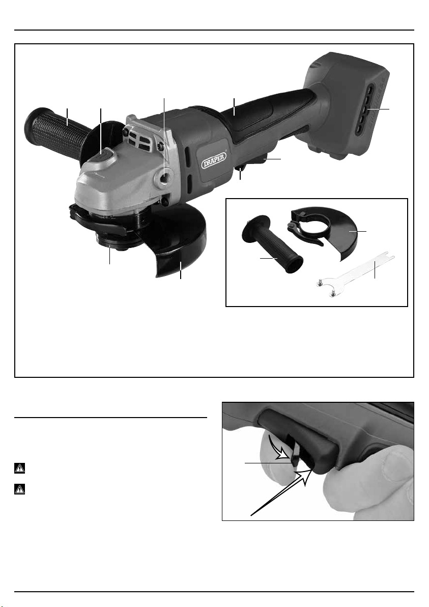
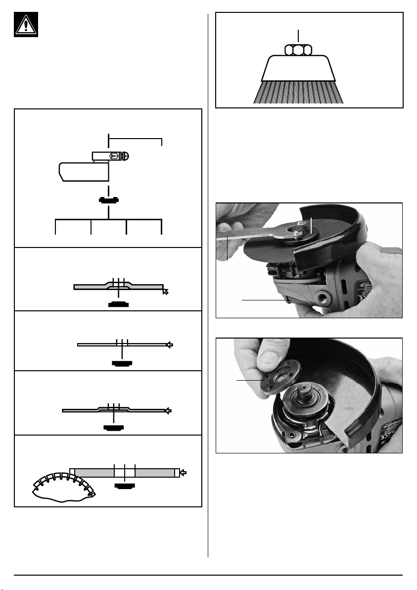
5. IDENTIFICATION – FIG.A
FIG.A
(1) Soft grip.
(2) Spindle lock.
(3) Locking ange.
(4) Safety trigger.
(5) Trigger.
(6) Adjustable disc guard
(Guard supplied is for grinding only).
(7) Auxiliary handle.
(8) Second xing point for auxiliary handle
(9) Disc changing spanner.
(10) Dust screen.
(1)
(2)
(7)
(3)
(8)
(6)
(4)
(5)
(10)
(9)
(6)
(7)
–
9
–
6.2 GRINDING
When performing grinding operations maintain an angle of
approximately 30° between the work surface and the disc
face.
Only use abrasives specically designed for this task.
Warning!
Important legal information:
– Cutting operations should only be attempted with the
“cutting” guard tted to this grinder.
– Please contact Draper Tools for further information on
how to purchase this optional accessory.
– This guard must be tted for your safety.
– When performing cutting-off operations do not incline
the machine as this can lead to the abrasive wheel
becoming jammed, damaged or excessively and
abnormally worn.
– Only use abrasives specically designed for this task.
Warning: As the abrasive wheel wears during use, its
diameter reduces. This reduces the peripheral speed and
the machine’s efciency. This results in increased load on
the grinding machine which if continued will damage the
motor. Ensure that the diameter of the wheel is within 25%
of its original size.
Important: Excessive pressure on the machine does not
result in a higher abrasive efciency. Excessive pressure
increases wear and tear on the accessory and will damage
the angle grinder which is not covered under the warranty.
6.3 FITTING THE GUARD - FIGS. 2–4
2
FIG.
(6)
3
FIG.
4
FIG.
To t:
Position the guard (6) onto the grinder collar with the
quick release lever open.
Rotate the guard until the spigot lines up with the cutout,
once located the guard can be rotated to the working
position and tightened.
To remove:
Open quick release lever, rotate the guard until the spigot
lines up with the cutout, and remove.
Warning!
Never attempt to operate this machine
without the guard securely tted and correctly positioned*.
* With the exception of wire cup brushes etc. which
negate the guards effectiveness.
6.4 FITTING/REPLACING
ACCESSORIES (sold separately)
– FIG. 5
Warning! Prior to mounting an abrasive wheel ensure
the expiry date has not expired, rendering it potentially
hazardous.
Warning! Selection of the correct accessory, suitable for
the intended application is vital. Seek guidance if
uncertain of selection.
Warning! The rated (no load) revolutions per minute of
the tool must not exceed the speed capacity of the
accessory. Please refer to the accessory manufacturers
instructions for information.
Visual Inspection:
– Prior to tting, abrasive/superabrasive wheels shall
be subject to a visual inspection.
Inspection:
– Each time after mounting, the abrasive/
superabrasive wheel shall be test run for a
reasonable time.
– The specied maximum operating speed of the
wheel shall not be exceeded.
– Damaged abrasives shall be destroyed.
– Always wear approved safety goggles.
–
10
–
Important information:
B, C, D :
For cutting applications, and to comply to current
legislation, it is necessary to replace the “grinding”
guard supplied with this machine with a “cutting”
guard (Please consult the Draper website or your
local stockist for details). High oscillation
frequency:
AB C
Grinder Spindle (M14)
E
D
A. Type 27:
Depressed Centre Grinding Wheel
B. Type 41:
Flat Cutting-off Wheel
C. Type 42:
Depressed Centre Cutting-off Wheel
D. Superabrasive Wheel
(Diamond/CBN Abrasive)
E. Wire Cup Brush
5
FIG.
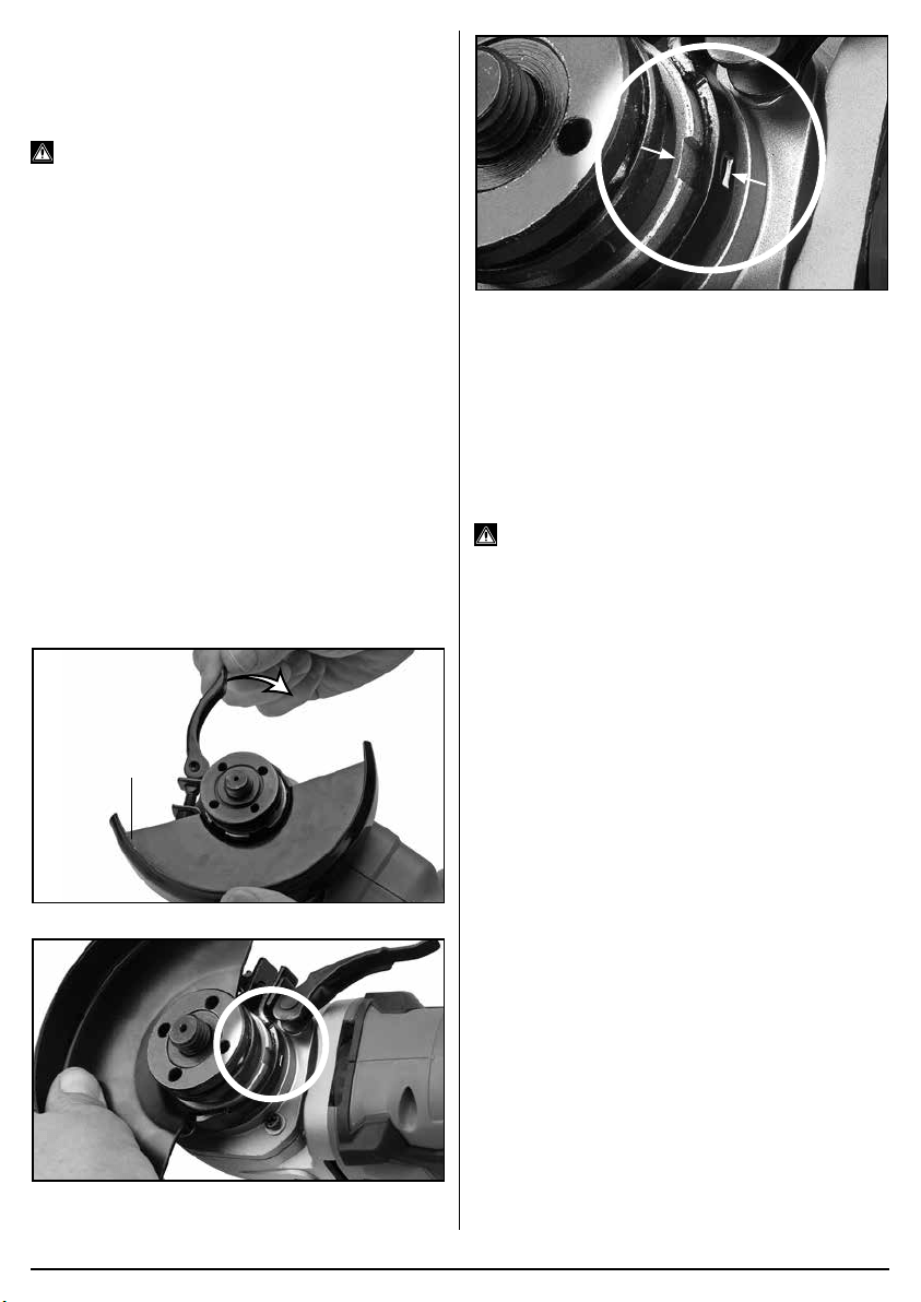
6.5 FITTING GRINDING DISCS - FIGS.
6–7
Press and hold the spindle lock button (2). Loosen
the locking ange (3) anti-clockwise using the pin
spanner (9) supplied. The spindle may rotate slightly
before the spindle lock fully engages.
6
FIG.
(9)
(2)
(3)
7
FIG.
(3)
Remove the locking ange only. Clean the anges and
spindle prior to tting any accessory. If the rear ange
is removed for cleaning, ensure it locates correctly on
the spindle ats when retting and does not spin freely.
When tting the appropriate accessory please refer to
(Fig.5) for specic details on the locking ange correct
orientation as applicable.
–
11
–
Securely tighten the locking ange clockwise using
the disc changing spanner (8) while holding down the
spindle lock (2).
Note: When using wire cup brushes the locking ange
is not required due to the design of the brushes. When
tted check the accessory is correct and, importantly
fully secure on the spindle.
Warning: Never press the spindle lock button (2)
while the spindle is in motion.
6.6 BATTERY PACK CHARGING –
FIGS. 8–9
This power product is supplied “bare”, without battery
pack or charger. For compatible batteries, chargers and
accessories please visit www.drapertools.com.
Important! Draper designated battery packs and
chargers must only be used with this product. Use of
any other third-party battery packs/chargers is
considered misuse and will invalidate the warranty.
Once connected to the mains supply, recharging of the
battery can be left generally unsupervised.
Warning! Check the condition of the charger and
battery prior to each charge. Do not use if there is any
sign of damage.
The battery pack is supplied un-charged and must be
charged before initial use.
To charge the battery pack (12):
– Plug the battery charger (11) unit into a suitable
mains power supply socket.
– The red LED (11.1) will illuminate to show the charger
has power.
– Slide the battery into the charger’s aligning pins.
– After a few seconds delay, the red LED will ash to
show that charging has begun, then changes to solid
red.
– Whilst the battery is charging, the green LED (11.2)
will ash, (the red LED will go from ashing to
constant red.
– When the battery is fully charged when the green
LED stops ashing and changes to solid green. The
red LED will turn off.
8
FIG.
(11.1)
(11.2)
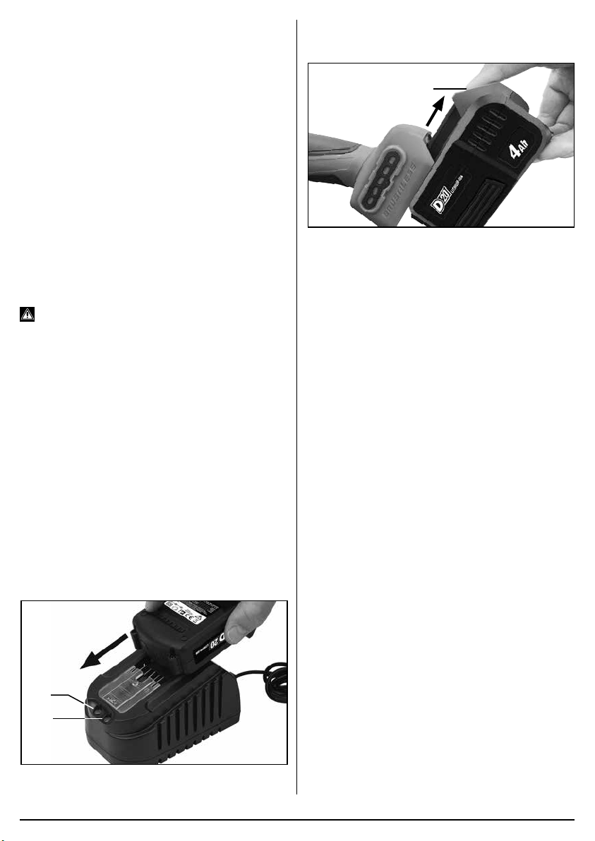
To release the battery pack:
– Press the battery release button (12.1) and gently
slide the battery pack off.
9
FIG.
(12.1)
6.7 BATTERY PACK PROTECTION
FEATURES
Overcharging protection: When the battery pack is
fully charged, the transformer/charger will automatically
shuts off, protecting the internal components.
Over-discharging protection: Stops the battery pack
from discharging beyond the recommended lowest
safety voltage.
Overheating protection: An internal thermistor cut-off
sensor shuts off the battery pack should it become too
hot during operation. For example, if the tool is
overloaded or used for extended periods. 30 minutes
cooling time may be required.
Current protection: If the battery is overloaded or the
maximum current draw exceeded, the battery will shut
off to protect internal components. The battery pack will
resume operation once the current draw is at a safe
level.
Short circuit protection: The battery pack will stop
operating immediately if it was to short circuit.
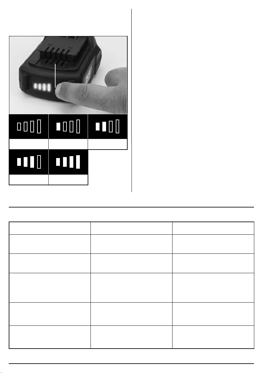
6.8 BATTERY PACK CHARGE STATUS
– FIG.10
Press the charge level indicator button (12.2) to display
the battery charge level.
(12.2)
0 – 10% 0 – 25%
25 – 50%
50 – 75% 75 – 100%
10
FIG.
6.9 BATTERY LIFE EFFICIENCY AND
CHARGING ADVICE
– A rechargeable battery will be hot immediately after
use. If such a battery is recharged immediately after
use the battery life will be shortened. Leave the
battery and recharge it after it has cooled.
– The battery needs to be warmed-up or cooled down
to prevent damaging to the batteries internal
components.
7. MAINTENANCE AND TROUBLESHOOTING
7.1 TROUBLESHOOTING GUIDE
Problems Possible cause Required action
Tool does not operate. – Battery pack no charge.
– Battery pack faulty or damaged.
– Re-charge battery pack.
– Replace battery pack.
Motor runs, but slowly/ losing
power.
– Battery pack no charge.
– Battery pack faulty or damaged.
– Re-charge battery pack.
– Replace battery pack.
Machine vibrates. – Wheel damaged or out of
balance.
– Wheel loose.
– Replace wheel.
– Stop machine immediately
– when stopped, ret accessory.
Wheel will not cut/grind. – Incorrect disc tted. – Fit correct disc for material/
application.
Battery pack doesn’t charge / non
illumination of charger.
– Fuse blown in charger plug.
– Charger faulty.
– Replace fuse.
– Replace charger.
–
12
–
–
13
–
7.2 MAINTENANCE
Regular inspection and cleaning reduces the necessity
for maintenance operations and will keep your tool in
good working condition.
Do not use solvents or fuels to clean the product. When
not in use, store the product in a safe, dry place.
8. WARRANTY
8.1 WARRANTY
Draper tools have been carefully tested and inspected
before shipment and are guaranteed to be free from
defective materials and workmanship.
Should the tool develop a fault, please return the
complete tool to your nearest distributor or contact:
Draper Tools Limited
UK: Chandler’s Ford, Eastleigh, Hampshire,
SO53 1YF. England.
EU: Oude Graaf 8, 6002 NL Weert (NL).
Telephone Sales Desk: +44 (0)23 8049 4333 or:
Product Helpline +44 (0)23 8049 4344.
A proof of purchase must be provided.
If upon inspection it is found that the fault occurring is
due to defective materials or workmanship, repairs will
be carried out free of charge. This warranty period
covering parts/labour is 24 months from the date of
purchase except where tools are hired out when the
warranty period is 90 days from the date of purchase.
This warranty does not apply to any consumable parts,
any type of battery or normal wear and tear, nor does it
cover any damage caused by misuse, careless or
unsafe handling, alterations, accidents, or repairs
attempted or made by any personnel other than the
authorised Draper warranty repair agent.
Note: If the tool is found not to be within the terms of
warranty, repairs and carriage charges will be quoted
and made accordingly.
This warranty applies in lieu of any other warranty
expressed or implied and variations of its terms are not
authorised.
Your Draper warranty is not effective unless you can
produce upon request a dated receipt or invoice to verify
your proof of purchase within the warranty period.
Please note that this warranty is an additional benet
and does not affect your statutory rights.
Draper Tools Limited.
9. DISPOSAL
9.1 DISPOSAL
Ensure that the machine is disposed of according to
national regulations at the end of its working life or when
it can no longer be repaired.
DO NOT:
• Dispose of power tools with domestic waste.
• Incinerate.
• Abandon in the environment.
• Dispose of WEEE as unsorted municipal waste.
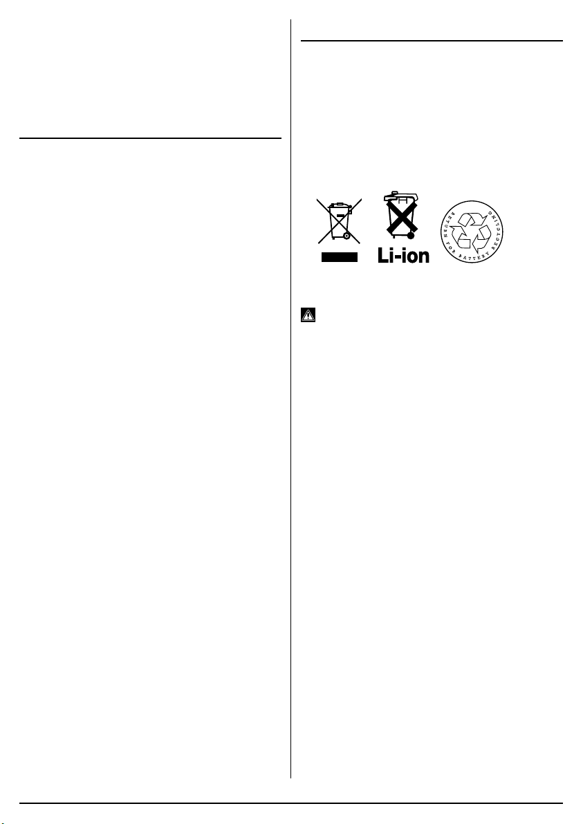
9.2 BATTERY PACK DISPOSAL
INFORMATION
Warning!
− Do not put battery packs in a re or mutilate – cells
may burst or release toxic materials.
− Do not short circuit cells, may cause burns.
− The battery pack must be removed from the
appliance before it is scrapped.
− The battery pack is to be disposed of safely.
− Do not mutilate batteries, corrosive electrolyte will be
released.
− Do not dispose of batteries or cells in a charged
condition.
Expired batteries must be recycled/disposed of in
accordance with the appropriate regulation or legislation.
They should be returned to your local warranty agent/
stockist.