
Installation and
Maintenance manual
LED Display Kit
[Models for indoor use]
LED-E012i-108
LED-E012i-217
LED-E015i-135
LED-E018i-162
LED-E025i-217
MODELS: LED-E012i, LED-E015i, LED-E018i, LED-E025i

Table of Contents
Important Information ...................................................................English-1
About the LED lamps ......................................................................English-4
Lamp break-in ......................................................................................................English-4
Contents ......................................................................................... English-5
Parts Name ....................................................................................English-7
Installation Example ......................................................................English-8
1. Installation location .......................................................................................................8
2. Installation Setup ....................................................................................................... 10
3. Wiring ....................................................................................................................... 22
4. Installing the pixel card ............................................................................................... 27
Screen Conguration ....................................................................English-29
Image Setting ..............................................................................English-38
Maintenance .................................................................................English-40
Troubleshooting ...........................................................................English-43
1. Display problems ........................................................................................................ 43
2. State monitoring using the software .............................................................................. 44
Specications ...............................................................................English-49
Diagram .......................................................................................English-50
English - 1
Important Information
Safety Precautions and Maintenance
FOR OPTIMUM PERFORMANCE, PLEASE NOTE
THE FOLLOWING WHEN SETTING UP AND
USING THE LED DISPLAY SYSTEM:
About the Symbols
To ensure safe and proper use of the product, this manual uses a number of symbols to prevent
injury to you and others as well as damage to property. The symbols and their meanings are
described below. Be sure to understand them thoroughly before reading this manual.
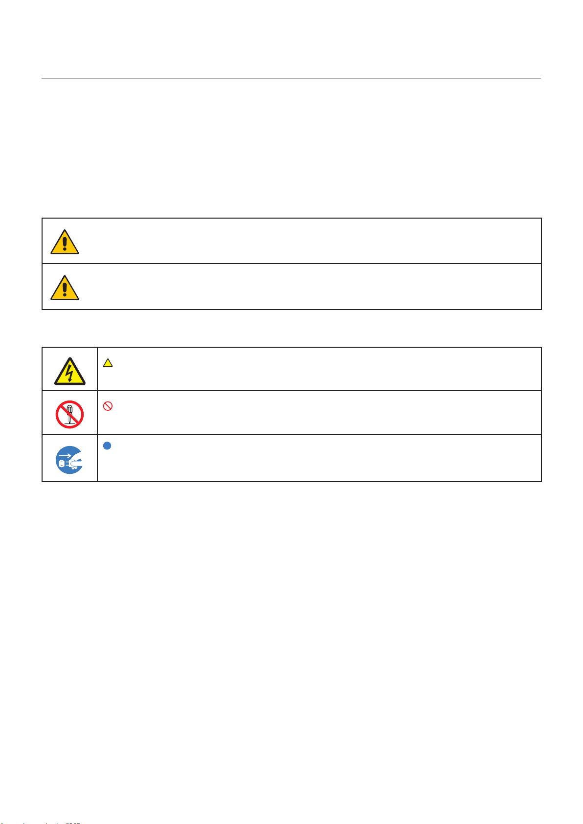
WARNING
Failing to heed this symbol and handling the product
incorrectly could result in accidents leading to major
injury or death.
CAUTION
Failing to heed this symbol and handling the product
incorrectly could result in personal injury or damage to
surrounding property.
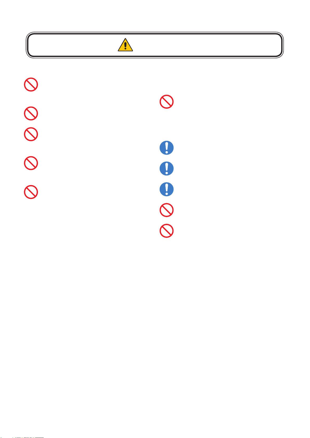
Examples of symbols
Indicates a warning or caution.
This symbol indicates you should be careful of electric shocks.
Indicates a prohibited action.
This symbol indicates something that must be prohibited.
Indicates a mandatory action.
This symbol indicates that the power cord should be unplugged from the
power outlet.
English - 2
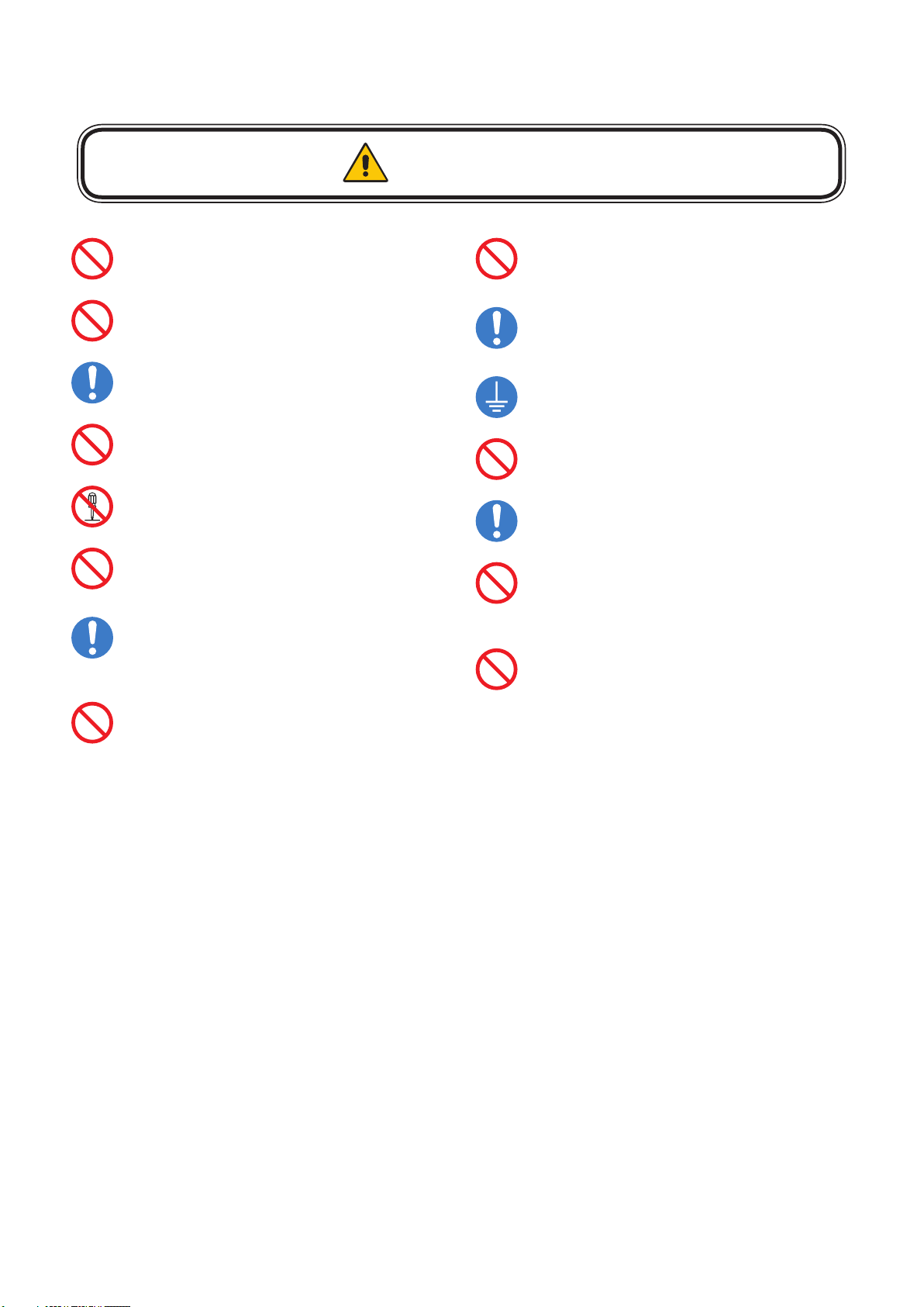
● Be sure to read the following before using the product to use it correctly and safely.
WARNING
Do not apply vibrations or shocks to the
product.
Do not install the product to unstable
locations or locations subject to vibrations.
Always ask a technician to perform the
installation.
Do not connect the cables with wet hands.
Otherwise, it may cause an injury or an
electrical shock.
Do not repair or modify the product yourself.
Otherwise, it may cause an injury, a re or an
electrical shock.
In case of thunder, do not touch the power
cord. Otherwise, it may cause an electrical
shock.
Connect the product to the correct voltage.
If the product is connected to a voltage other
than the specied voltage, it may lead to a
re or an electrical shock.
In case of a malfunction (nothing is displayed
on the screen, etc.) or if smoke, abnormal
heat, or a strange sound or odor is generated,
turn the power off and immediately ask a
technician or your retailer for repair.
Install the product so that the vents are not
obstructed.
Make sure there are enough people available
to ensure safety (at least two people) when
installing or moving the product. Otherwise, it
may lead to an injury.
Be sure to ground the product. If the product
is not grounded, there is a risk of electrical
shock in case a malfunction occurs.
In case foreign matter has entered into the
product, immediately disconnect the power
supply and stop using the product.
After the installation, if a problem such as
loose screws occurs, immediately ask a
technician or your retailer for repair.
Do not put objects into the product.
Otherwise, it may cause a re or an electrical
shock.
In case the product is in contact with water
or another liquid, immediately disconnect the
power supply and stop using the product. If
you continue using the product in that state,
it may lead to a malfunction, a re, or an
electrical shock.
English - 3
This product can only be serviced in the country where it was purchased.
CAUTION
Do not damage the power cord. Do not put
heavy objects on it, place it near heaters, pull
it with excessive strength, or apply a strong
force on it while it is bent.
A damaged power cord may cause a re or an
electrical shock.
Do not install the product in narrow places
where heat tends to build up.
Do not use the product in an environment
with low heat dissipation.
Otherwise, it may cause a malfunction.
The RJ-45 port of the product is for use
with the product only. Do not connect it to a
network. Connecting this port to a network
that may receive over-voltage current may
cause damage to the product or an electrical
shock.
Do not use the product in a vehicle or another
means of transportation.
Do not use or store the product in the
following places.
• Near heaters
• Places with lots of humidity or dust, or
places subject to oily smoke
• Places where water or oil may splash
• Places with lots of corrosive gases, such as
near hot springs
• Places where the product may freeze
• Do not place the product on its side, face
down, or upside down.
• Places with lots of vibrations
If you will not be using the product for a long
time, disconnect it from the power distributor
for safety purposes.
Disconnect the power supply when
performing the maintenance.
Install the product in accordance with the
local laws and regulations.
Do not place the product under direct sunlight
or near heaters.
This product is designed to be used indoors.
Do not use it outdoors. Otherwise, it may
cause a malfunction.
English - 4
About the LED lamps
LED lamps are sensitive to static electricity and surge voltage, which may damage their components
and decrease their reliability.
Take measures against static electricity during the installation. Do not touch the LED display areas.
The LED lamps may absorb and hold moisture during the LED module installation or if not used for
a long time. Therefore, in such cases, the brightness must be increased gradually during a break-in
period before setting the normal brightness.
If the LED lamps are lit with 100% brightness while moisture is retained, the temperature will rise very
quickly and the water inside the lamps will evaporate and expand. This will cause the encapsulating
resin to expand, which may lead to separation of the boundary surface inside the LED lamps. This
separation can cause the LED lamps not to light up properly.
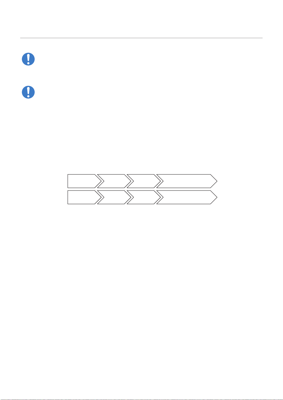
Lamp break-in
Congure the brightness settings as shown below with a video displayed on the LED module.
After a break-in period of approximately 3 hours, the LED module can be used under normal
conditions.
Time since start-up:0
(just after start-up)
1 hour 2 hours 3 hours
Full white
Normal operation70%50%
80%60%40%
Brightness
value 20%
Normal operation
Video content
English - 5
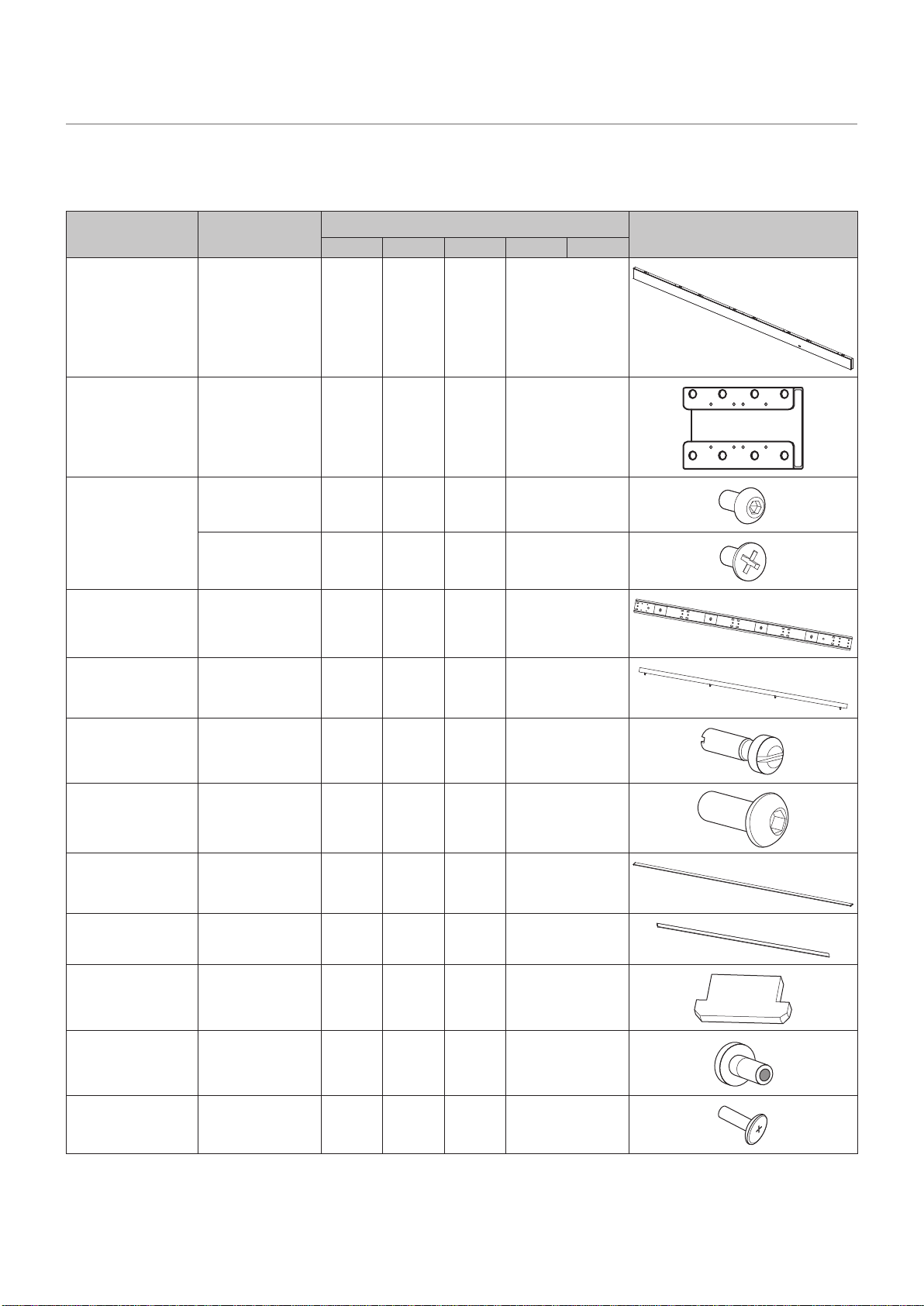
Contents
The supplied parts are as follows.
In case one of these parts is missing or damaged, contact the retailer.
Parts Specications
Quantity
LED-E012i-108 LED-E015i-135 LED-E018i-162 LED-E012i-217 LED-E025i-217
Bottom frame 1 1 1 2
Bottom frame
connecting part
- - - 1
Bottom frame
connecting screw
PM3 - - - 8
KM3 - - - 8
Mounting bar 2 2 3 4
Alignment bar 2 2 2 2
Cabinet hanger pin Head diameter
10 mm x 25 mm
16 20 36 64
Bottom frame
screw
M6 x 16 6 6 9 12
Over frame (top) 1 1 1 1
Over frame (left,
right)
2 2 2 2
Corner frame 2 2 2 2
Slot nut M3 x 13 mm 12 15 18 24
Screw for the slot
nut
M3 x 10 mm 12 15 18 24
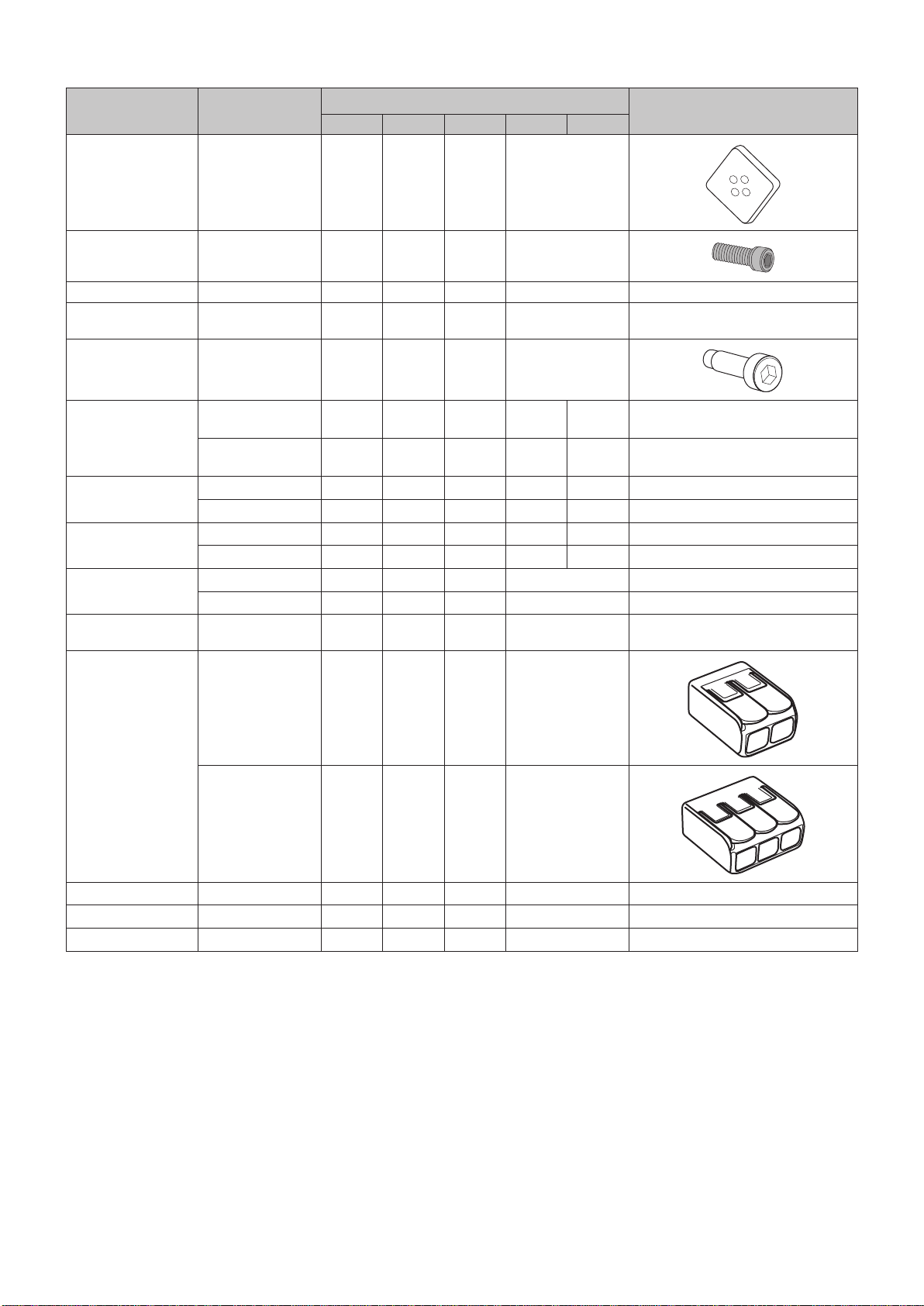
English - 6
Parts Specications
Quantity
LED-E012i-108 LED-E015i-135 LED-E018i-162 LED-E012i-217 LED-E025i-217
Cabinet alignment
bracket
35 x 35 x 6 mm 10 12 14 18
Fixing screw for the
cabinet alignment
bracket
Hexagonal socket
head screw (M4
x 12)
40 48 56 72
Pixel card 64 100 144 256
Cabinet 600 mm x 337.5
mm
16 25 36 64
Connection screw
for LED modules
M6 x 26 mm 56 90 132 240
LED controller
Novastar MCTRL
660Pro
1 1 1 - 1
Novastar MCTRL
4K
- - - 1 -
LAN cable for the
LED modules
750 mm - - - - 4
200 mm 12 20 30 48 56
LAN cable for the
LED controller
20000 mm 4 5 6 8 8
24000 mm - - - 8 -
Power cord for the
LED modules
950 mm 2 2 - -
300 mm - 1 6 8
Power cord for the
LED controller
1 1 1 1
Power cord
connector
WAGO (2pcs) 4 6 12 16
WAGO (3pcs) 2 3 6 8
USB ash memory
1 1 1 1
Safety Manual
1 1 1 1
Packing list
1 1 1 1
English - 7
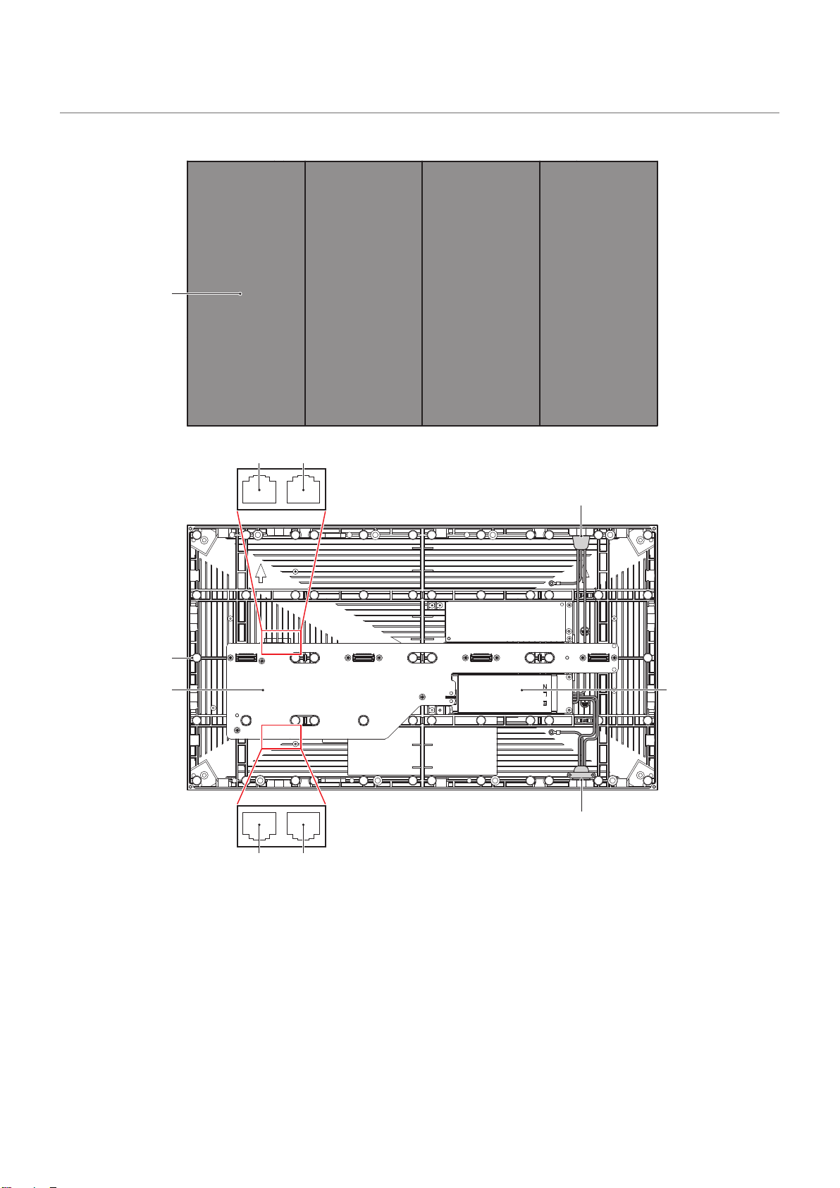
Parts Name
5
3 4
1
2
6
7
5
3 4
1
Pixel card
2
Cabinet
3
LAN cable input/output
4
LAN cable input (not used with this product)
5
Power cord input/output
6
Hub board
7
Power unit
English - 8
Installation Example
1. Installation location
Before the installation, be sure to review the following safety precautions to ensure proper and safe
installation.
CAUTION
• Ask a technician to perform the installation.
• Make sure the product is moved and installed by enough people to ensure safety.
• Make sure that the beams or the other structures to which the product is installed have enough strength to
support the weight of the product, and make sure that the product is securely xed.
• Do not install directly the product to a surface that has not enough strength.
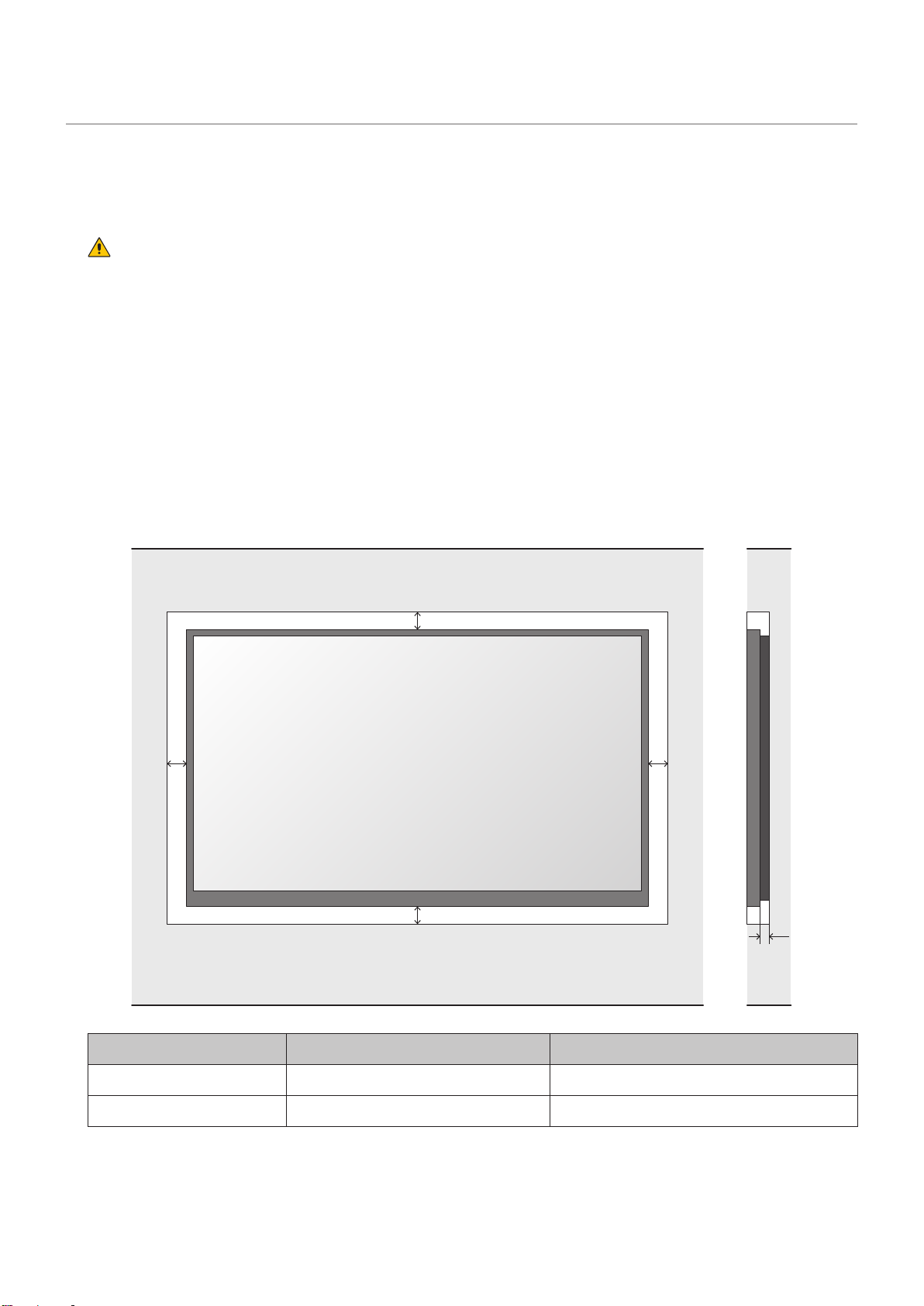
• When installing the product in a narrow place (in a wall, etc.), leave gaps around the LED screens as
shown in the gure below to prevent an increase in the temperature. The gure below is only an example.
Pay particular attention to the installation environment (heat from the external environment, direct
sunlight, heat generated by the number of displays) in order to facilitate cooling of the LED modules.
If cooling is not sufcient, take measures, such as increasing the distance from the walls or installing a
forced-air cooling system.
Ask a technician or your retailer for more details.
A A
C
B
B
A B C
min distance to sides min. distance to top and bottom Distance between wall and system
60 mm 60 mm 20 mm
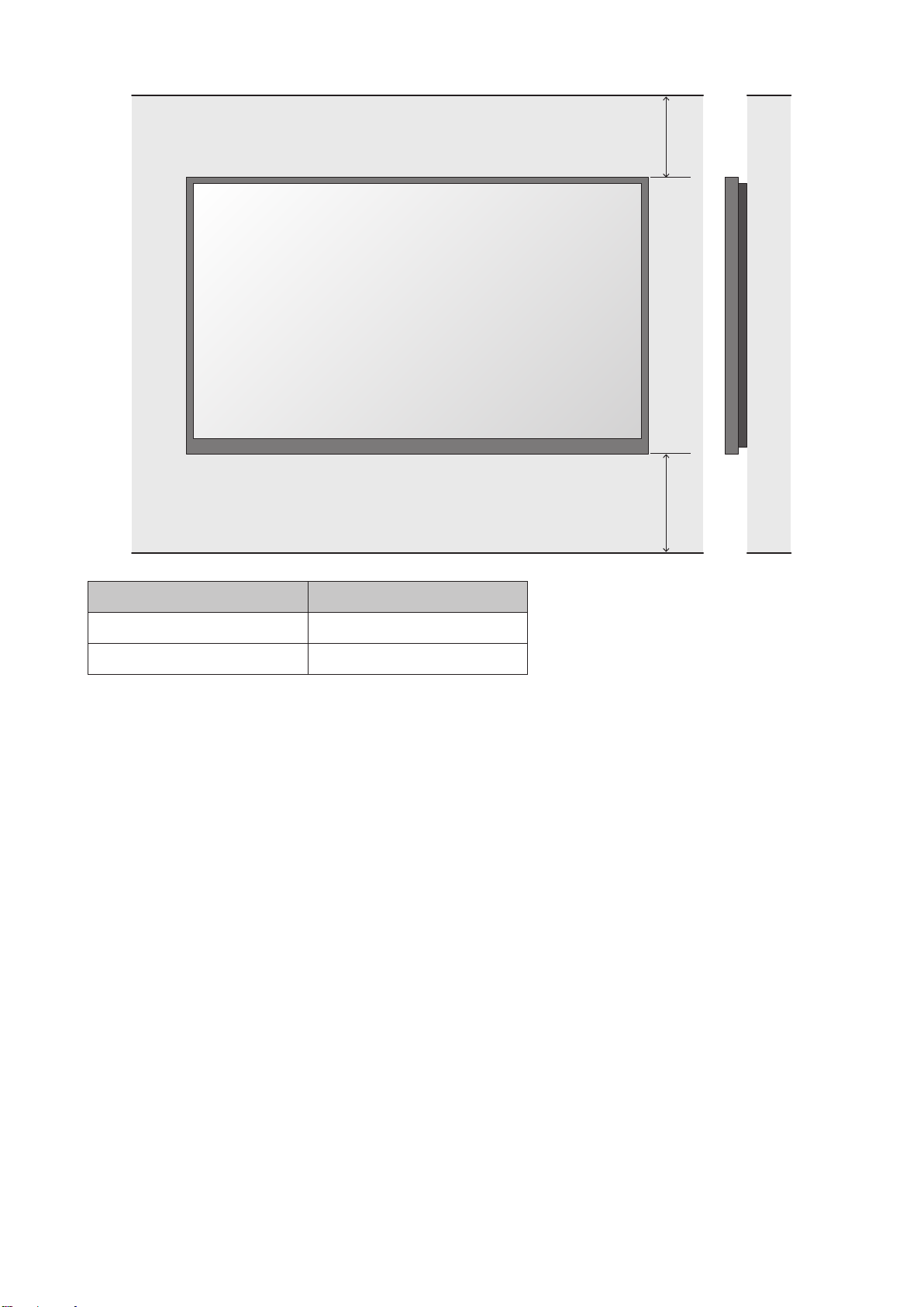
English - 9
D
E
D E
min. distance to ceiling min. distance to oor
500 mm 700 mm
English - 10
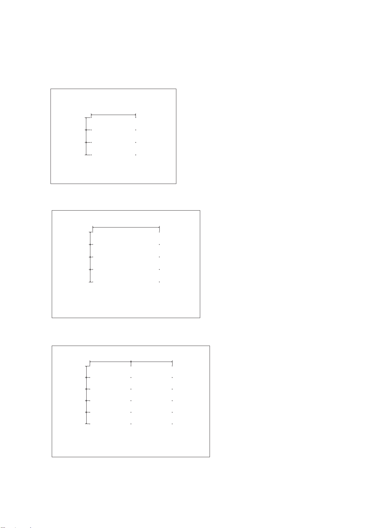
2. Installation Setup
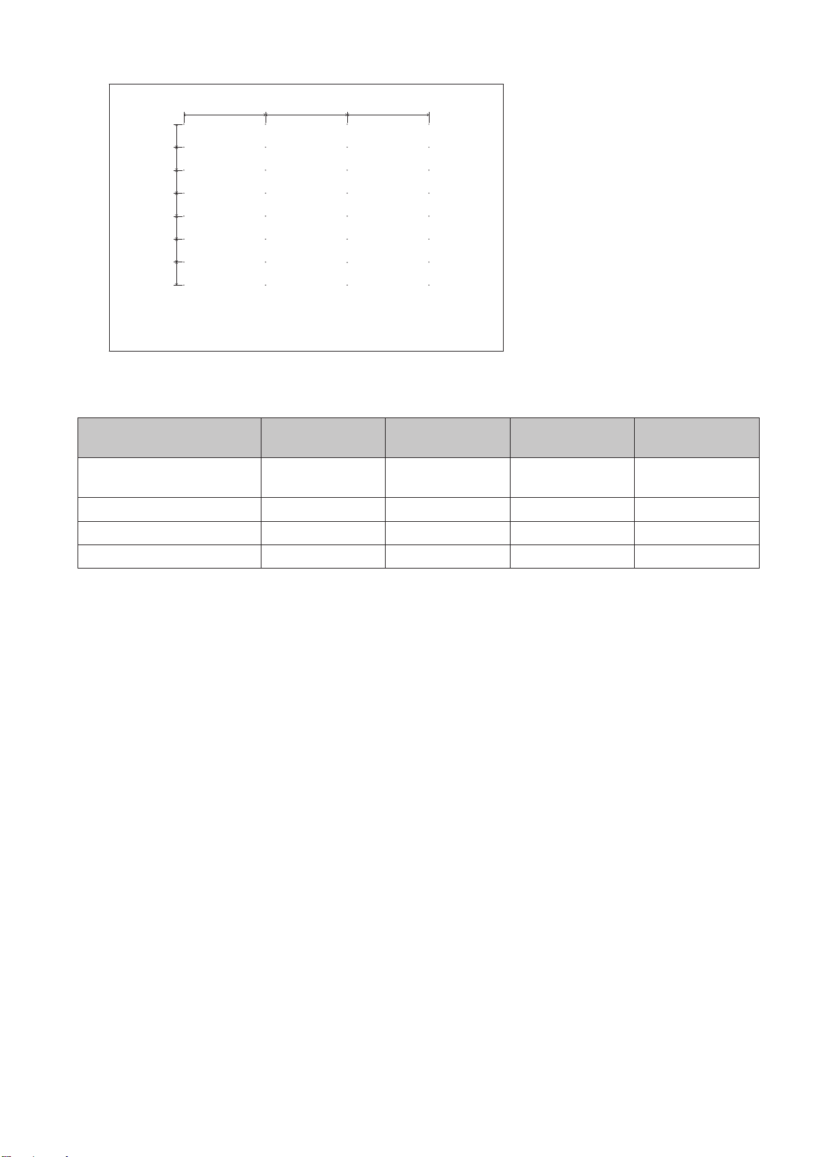
2.1 Mark the positions of the anchor points on the wall
• Mark the positions of the holes you will make for the anchor points (refer to the gures below and the
“Anchor points number and positions” table on the next page).
• Before making the holes, check the verticality of the marks using a spirit level.
1200 mm
337.5 mm
337.5 mm
337.5 mm
Anchor points positions: LED-E012i-108
1800 mm
337.5 mm
337.5 mm
337.5 mm
337.5 mm
Anchor points positions: LED-E015i-135
1200 mm
337.5 mm
337.5 mm
337.5 mm
337.5 mm
337.5 mm
1200 mm
Anchor points positions: LED-E018i-162
English - 11
1200 mm 1200 mm 1200 mm
337.5 mm
337.5 mm
337.5 mm
337.5 mm
337.5 mm
337.5 mm
337.5 mm
Anchor points positions: LED-E012i-217, LED-E025i-217
Anchor points number and positions
Frame set LED-E012i-108 LED-E015i-135 LED-E018i-162
LED-E012i-217,
LED-E025i-217
Anchor points
(horizontal x vertical)
2×4 2×5 3×5 4×8
Horizontal distance 1200 mm 1800 mm 1200 mm 1200 mm
Vertical distance 337.5 mm 337.5 mm 337.5 mm 337.5 mm
Anchor size Ø10 mm Ø10 mm Ø10 mm Ø10 mm
2.2 Make the holes at the anchor positions
• Make holes at the anchor positions using a suitable tool.
• Use screw anchors/anchor plugs as required.
• Remove the dust or dirt, and wipe off any drilling chips and dust.
English - 12
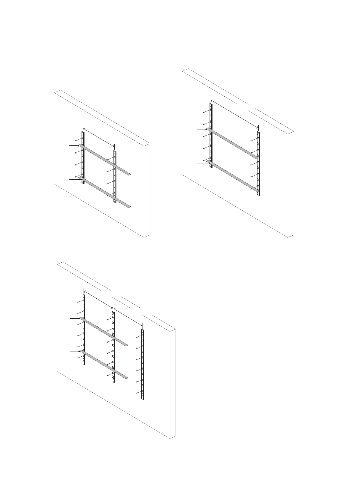
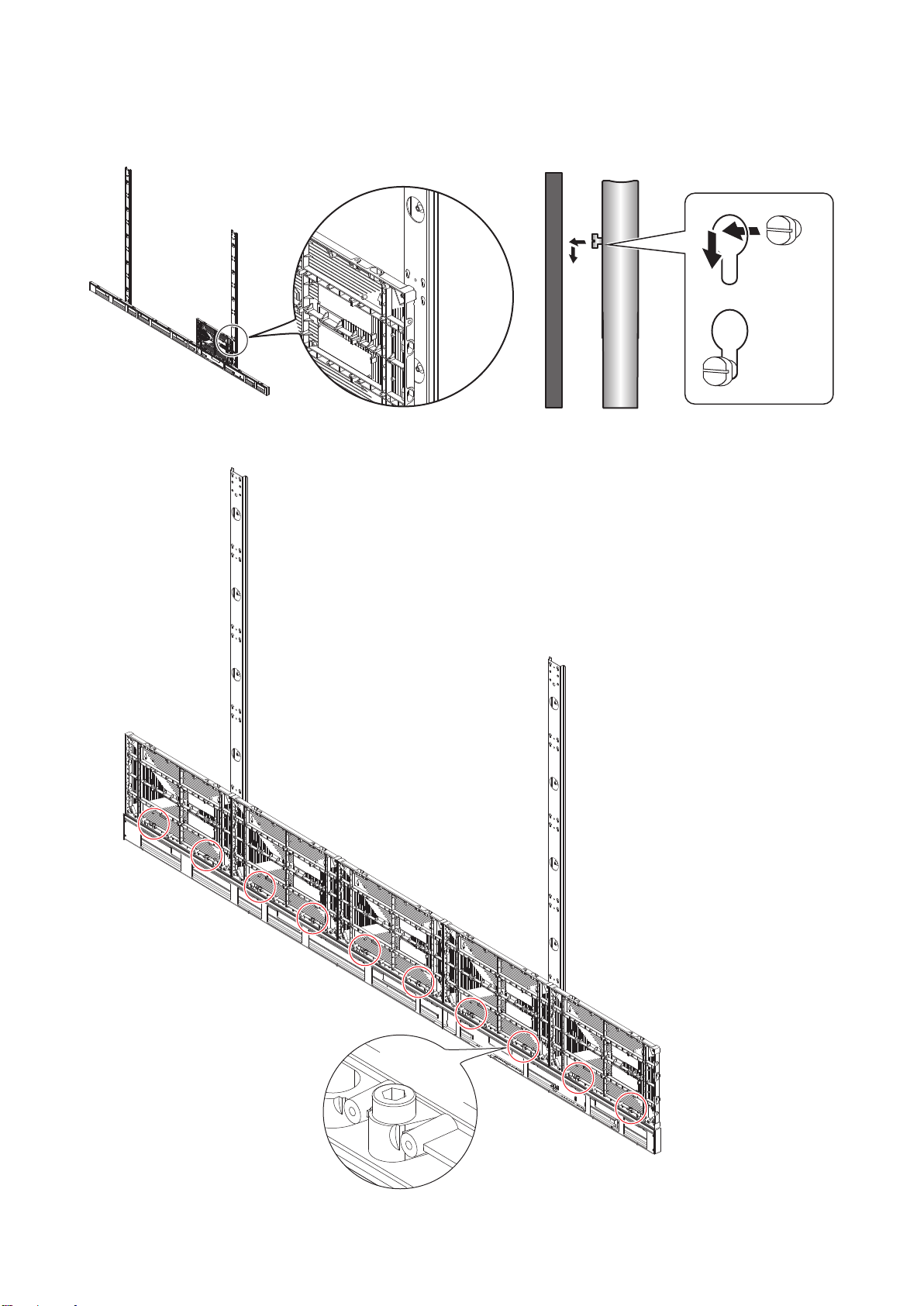
2.3 Install the mounting bars
(1) Install the mounting bars on the anchor points on the wall.
(2) Check the distance between the mounting bars using the alignment bars.
1200 mm
Alignment bar
Alignment bar
1800 mm
Alignment bar
Alignment bar
LED-E012i-108 LED-E015i-135
1200 mm
1200 mm
Alignment bar
Alignment bar
LED-E018i-162
English - 13
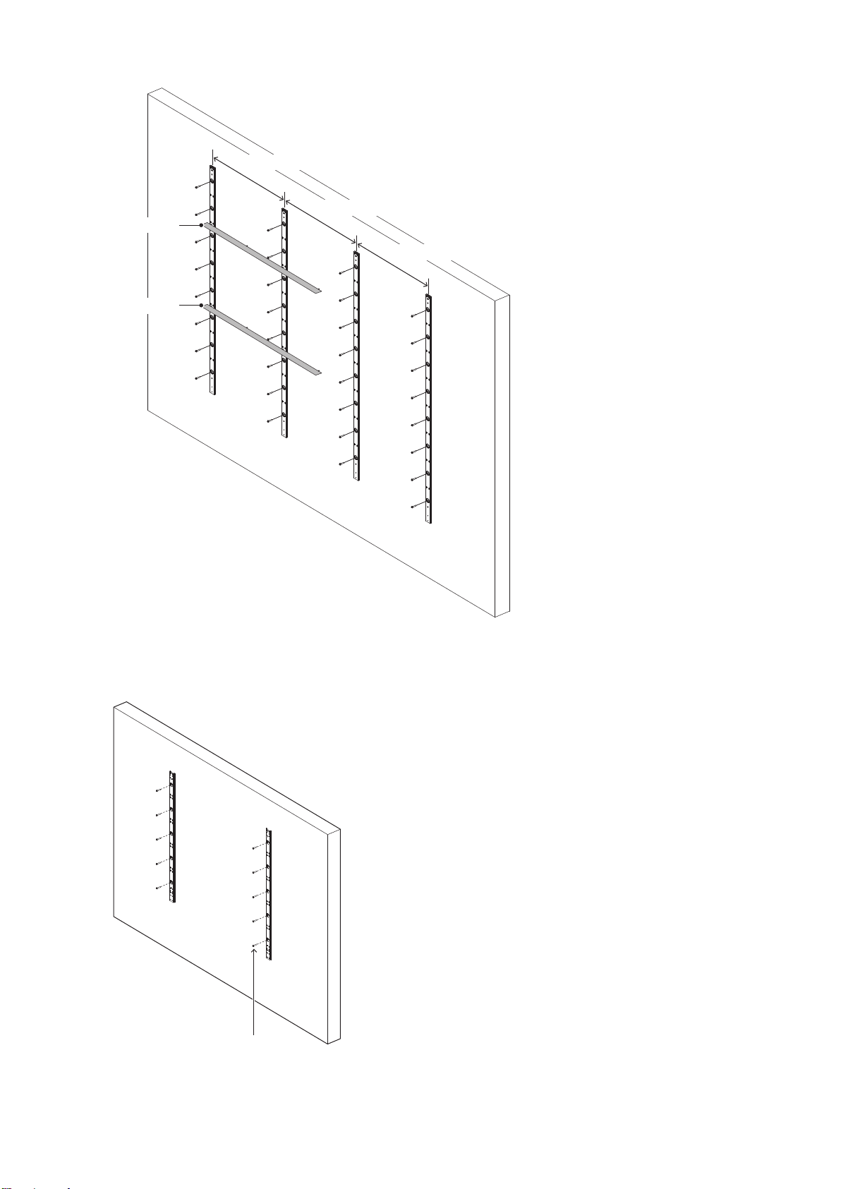
1200 mm
1200 mm
1200 mm
Alignment bar
Alignment bar
LED-E012i-217, LED-E025i-217
(3) Check the evenness using a spirit level and the alignment bars together. Adjust the positions if required.
M10 screws
Wall mounted: Mounting bar installation (LED-E015i-135)
English - 14
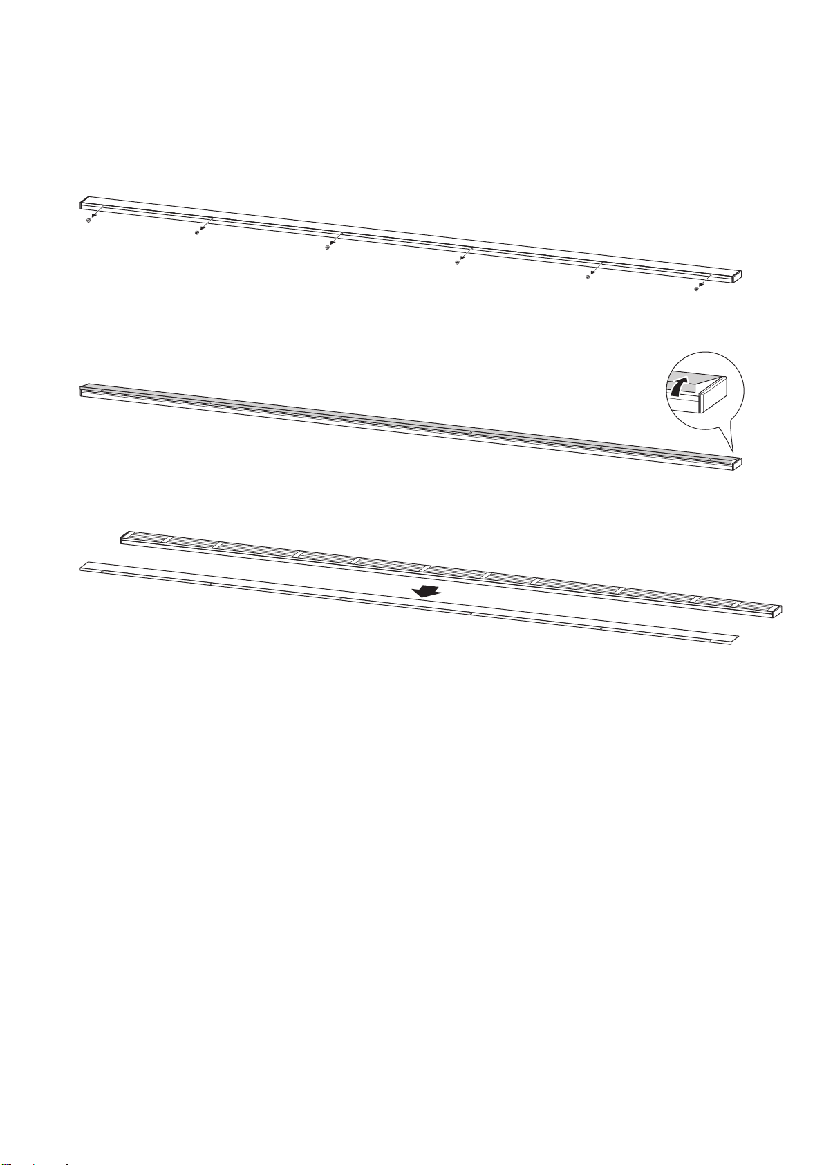
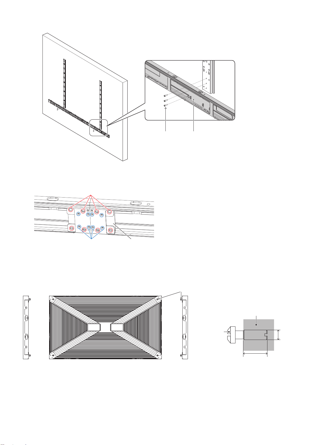
2.4 Install the bottom frame
Remove the bottom frame cover and install the bottom frame using M6 screws.
How to remove the bottom cover
(1) Remove the screws securing the bottom frame cover.
(2) Raise the front of the bottom frame cover.
(3) Pull the bottom frame cover toward you to remove it.
English - 15
Bottom frameM6 screws
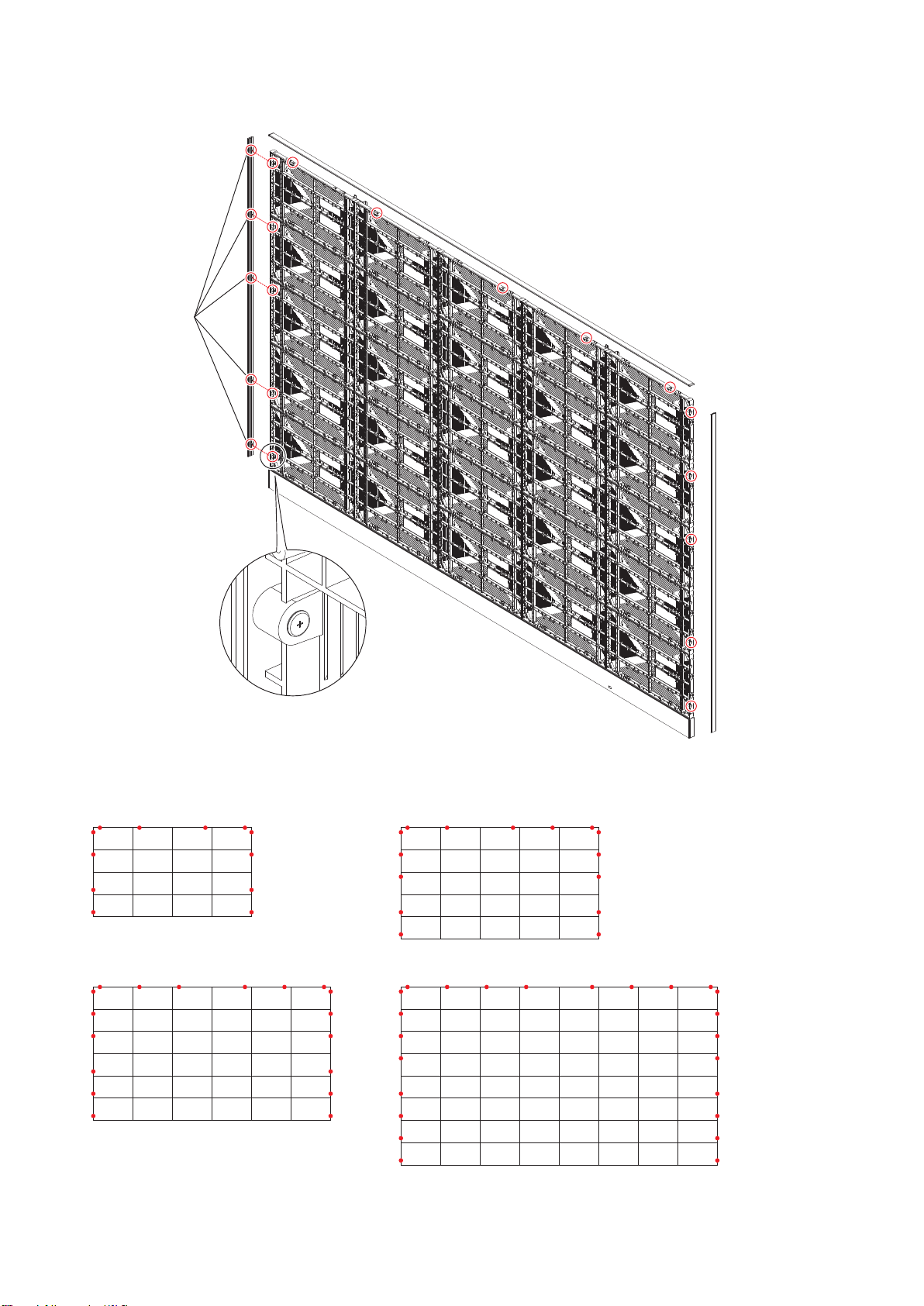
When using the 8 x 8 frame set, use the bottom frame connecting part to install the bottom frame.
Bottom frame connecting screw (PM3)
(8 red circles)
Bottom frame connecting screw (KM3)
(8 blue circles)
Bottom frame connecting part
2.5 Install the cabinet hanger pins to the back of the cabinets
Insert the hanger pins into the four corners of the cabinets up to where there is a difference in their diameter.
Hanger pin
LED cabinet
M6
15 mm
Hanger pin
English - 16
2.6 Install the cabinets
Hook the hanger pins, which have been inserted into the cabinets, into the holes on the mounting bars starting
from the lowest row.
Fix temporarily the cabinets of the rst row to the bottom frame.
English - 17
Hook the hanger pins of the cabinets of the second row to the mounting bars.
Secure the LED cabinets together using connection screws for LED modules. Do not tighten the screws
completely.
After you have installed two rows of cabinets, align the surfaces of the cabinets using the cabinet alignment
brackets.
A
When the cabinets’ surfaces are aligned, securely tighten the cabinets of the rst row to the bottom frame, the
cabinets of the rst row together, as well as the cabinets of the rst row with the cabinets of the second row.
Remove the cabinet alignment brackets after the screws have been tightened.
Adjust the position of the cabinet and the mounting bar by rotating the screws A on the gure with a at blade
screwdriver. Rotate the screws counterclockwise to bring the cabinet closer to the mounting bar.
Follow the same procedure to install the next row of cabinets and align their surfaces.
Connect the power cord and the LAN cable from the opening at the back of the bottom frame.
English - 18
How to connect the power cord
(1) Raise the lever.
(2) Insert the wire. (3) Return the lever to its previous
position.
Wire sizes compatible with the power connector (WAGO) are as follows.
Solid core: φ1.6 to 2.0 mm
IV 7-stranded core: 2.0 to 3.5 mm
2
WARNING
Pay attention to the wire colors of the power cord when connecting the cord. If the cables are not connected
correctly, it may lead to a re or an electrical shock.
Blue (N)
Brown (L)
Yellow green (Ground)
Install the bottom frame cover using the screws when it was installed (on the front).
Black at-heat screw M4
English - 19
Insert the slot nuts inside the over frame into the holes of the connection screws for the LED modules and x
them with M3 screws.
Slot nuts
Install the corner parts to the over frame (top) and install it on the top of the cabinets.
Slot nut installation locations
LED-E012i-217, LED-E025i-217
LED-E015i-135
LED-E012i-108
LED-E018i-162
English - 20
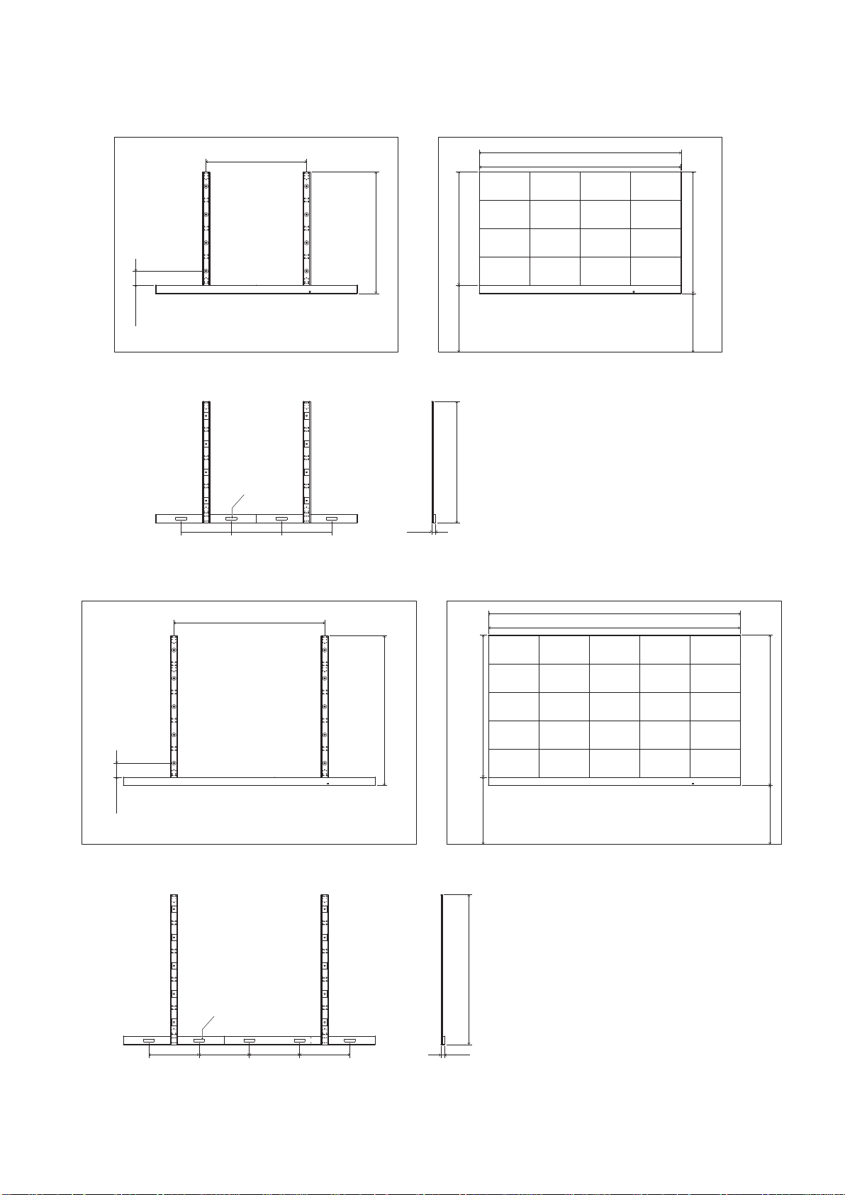
2.7 Assembly diagrams
LED-E012i-108
A
A
A
A
A
A
A
A
A
A
A
A
A
A
A
A
166.75
1449.75
1449.75
1356
1456
800
700
1200
600
Through
hole for the
LAN cable
600 600
50
2412
2400
LED-E015i-135
A
A
A
A
A
A
A
A
A
A
A
A
A
A
A
A
A
A
A
A
A
A
A
A
A
1787.3
1787.3
1693.5
1793.5
800
700
166.8
1800
3000
3012
600 600 600 600 50
Through hole for
the LAN cable
English - 21
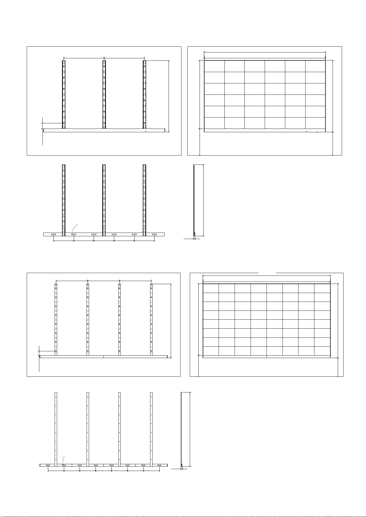
LED-E018i-162
A
A
A
A
A
A
A
A
A
A
A
A
A
A
A
A
A
A
A
A
A
A
A
A
A
A
A
A
A
A
A
A
A
A
A
A
2124.75
2124.75
2031
2131
800
700
166.75
1200 1200
3600
3612
600 600 600 600 600
50
Through
hole for the
LAN cable
LED-E012i-217, LED-E025i-217
A A A A A A A A
A A A A A A A A
A A A A A A A A
A A A A A A A A
A A A A A A A A
A A A A A A A A
A A A A A A A A
A A A A A A A A
2799.75
2799.75
2706
2806
800
700
166.75
1200 1200 1200
4800
4812
600 600 600 600 600 600 600 50
Through
hole for
the LAN
cable
English - 22
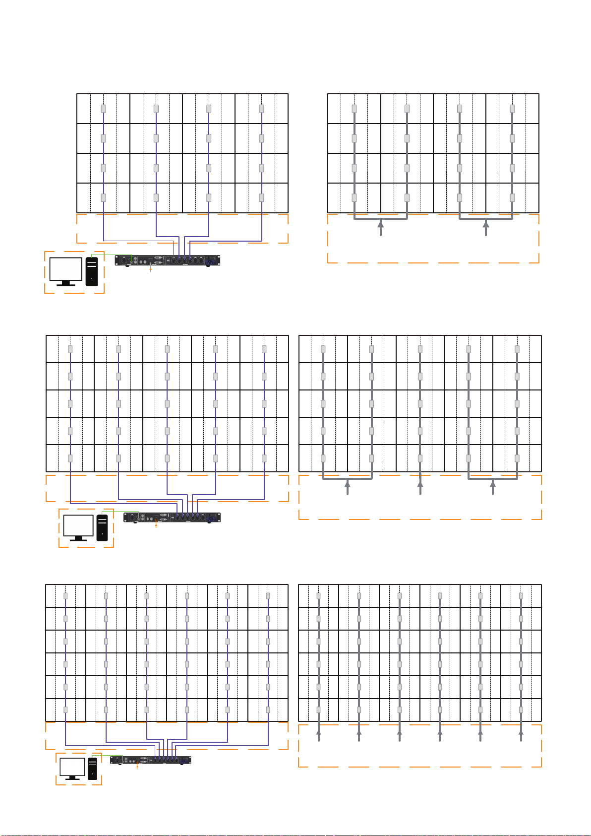
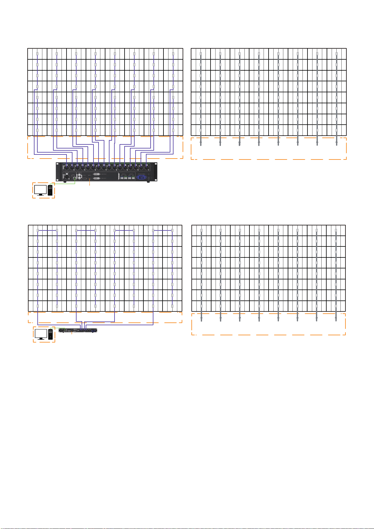
3. Wiring
LED-E012i-108
LED Controller Main
Control PC
by client
by client
100V/15A
or
200V/15A
by client
100V/15A
or
200V/15A
HDMI 1
RV
RV
RV
RV
RV
RV
RV
RV
RV
RV
RV
RV
RV
RV
RV
RV
PSU
PSU
PSU
PSU
PSU
PSU
PSU
PSU
PSU
PSU
PSU
PSU
PSU
PSU
PSU
PSU
LED-E015i-135
LED Controller Main
Control PC
by client
by client
by client
100V/15A
or
200V/15A
100V/15A
or
200V/15A
100V/15A
or
200V/15A
HDMI 1
RV
RV
RV
RV
RV
RV
RV
RV
RV
RV
RV
RV
RV
RV
RV
RV
RV
RV
RV
RV
RV
RV
RV
RV
RV
PSU
PSU
PSU
PSU
PSU
PSU
PSU
PSU
PSU
PSU
PSU
PSU
PSU
PSU
PSU
PSU
PSU
PSU
PSU
PSU
PSU
PSU
PSU
PSU
PSU
LED-E018i-162
LED Controller Main
Control PC
by client
by client
by client
100V/15A
or
200V/15A
100V/15A
or
200V/15A
100V/15A
or
200V/15A
100V/15A
or
200V/15A
100V/15A
or
200V/15A
100V/15A
or
200V/15A
HDMI 1
RV
RV
RV
RV
RV
RV
RV
RV
RV
RV
RV
RV
RV
RV
RV
RV
RV
RV
RV
RV
RV
RV
RV
RV
RV
RV
RV
RV
RV
RV
RV RV RV RV RV RV
PSU
PSU
PSU
PSU
PSU
PSU
PSU
PSU
PSU
PSU
PSU
PSU
PSU
PSU
PSU
PSU
PSU
PSU
PSU
PSU
PSU
PSU
PSU
PSU
PSU
PSU
PSU
PSU
PSU
PSU
PSU PSU PSU PSU PSU PSU
English - 23
LED-E012i-217
LED Controller Main
Control PC
by client
by client
HDMI 1
RV
RV
RV
RV
RV
RV
RV
RV
RV
RV
RV
RV
RV
RV
RV
RV
RV
RV
RV
RV
RV
RV
RV
RV
RV
RV
RV
RV
RV
RV
RV RV RV RV RV RV
RV
RV
RV
RV
RV
RV
RV
RV
RV
RV
RV RV
RV RV RV RV RV RV
RV RV RV RV RV RV
RV RV
RV RV
by client
PSU
PSU
PSU
PSU
PSU
PSU
PSU
PSU
PSU
PSU
PSU
PSU
PSU
PSU
PSU
PSU
PSU
PSU
PSU
PSU
PSU
PSU
PSU
PSU
PSU
PSU
PSU
PSU
PSU
PSU
PSU PSU PSU PSU
PSU PSU
PSU
PSU
PSU
PSU
PSU
PSU
PSU
PSU
PSU
PSU
PSU PSU
PSU PSU PSU PSU PSU PSU
PSU PSU PSU PSU PSU PSU
PSU PSU
PSU PSU
100V/15A
or
200V/15A
100V/15A
or
200V/15A
100V/15A
or
200V/15A
100V/15A
or
200V/15A
100V/15A
or
200V/15A
100V/15A
or
200V/15A
100V/15A
or
200V/15A
100V/15A
or
200V/15A
LED-E025i-217
LED Controller Main
Control PC
by client
by client
HDMI 1
RV
RV
RV
RV
RV
RV
RV
RV
RV
RV
RV
RV
RV
RV
RV
RV
RV
RV
RV
RV
RV
RV
RV
RV
RV
RV
RV
RV
RV
RV
RV RV RV RV RV RV
RV
RV
RV
RV
RV
RV
RV
RV
RV
RV
RV RV
RV RV RV RV RV RV
RV RV RV RV RV RV
RV RV
RV RV
by client
PSU
PSU
PSU
PSU
PSU
PSU
PSU
PSU
PSU
PSU
PSU
PSU
PSU
PSU
PSU
PSU
PSU
PSU
PSU
PSU
PSU
PSU
PSU
PSU
PSU
PSU
PSU
PSU
PSU
PSU
PSU PSU PSU PSU
PSU PSU
PSU
PSU
PSU
PSU
PSU
PSU
PSU
PSU
PSU
PSU
PSU PSU
PSU PSU PSU PSU PSU PSU
PSU PSU PSU PSU PSU PSU
PSU PSU
PSU PSU
100V/15A
or
200V/15A
100V/15A
or
200V/15A
100V/15A
or
200V/15A
100V/15A
or
200V/15A
100V/15A
or
200V/15A
100V/15A
or
200V/15A
100V/15A
or
200V/15A
100V/15A
or
200V/15A
English - 24
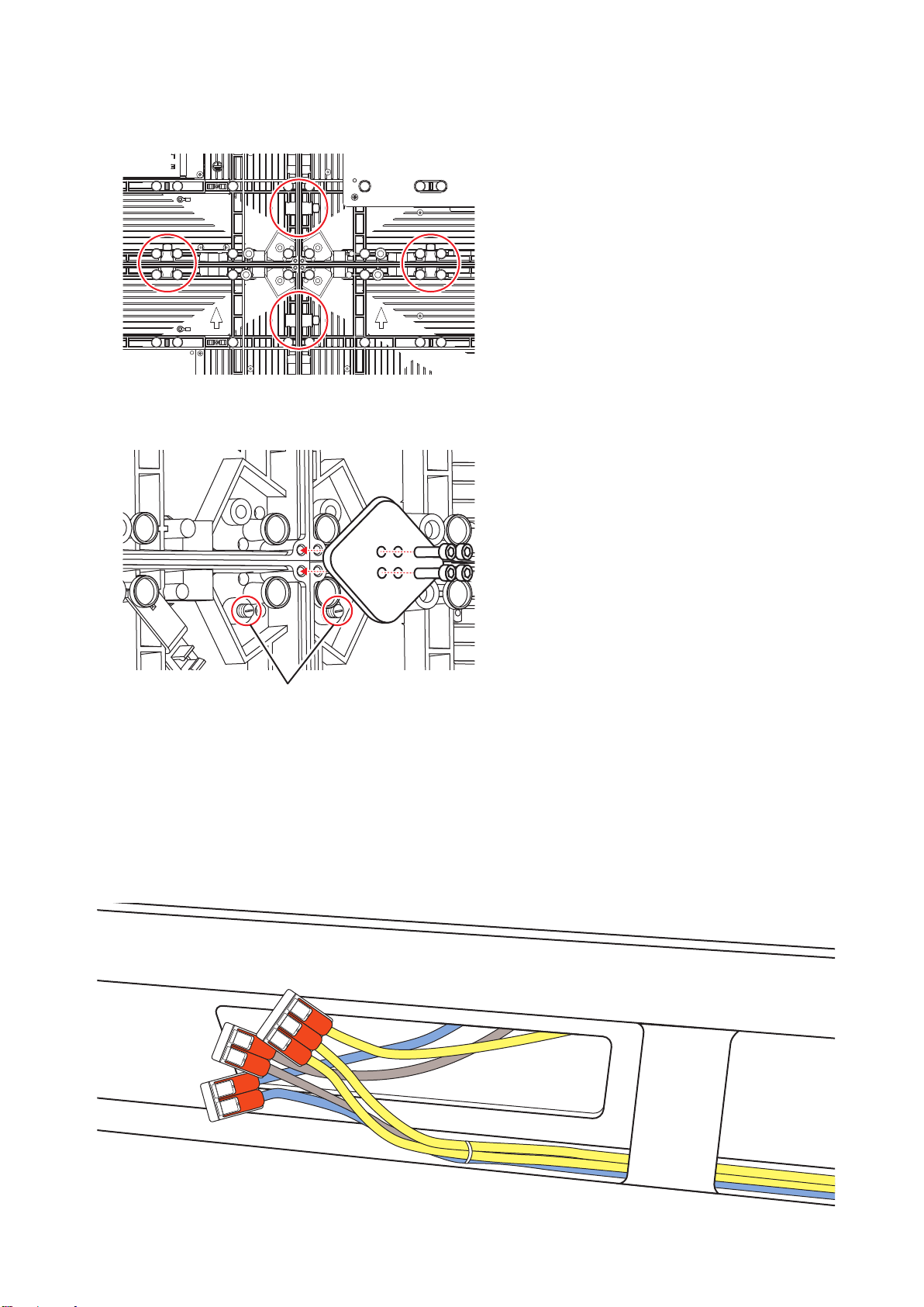
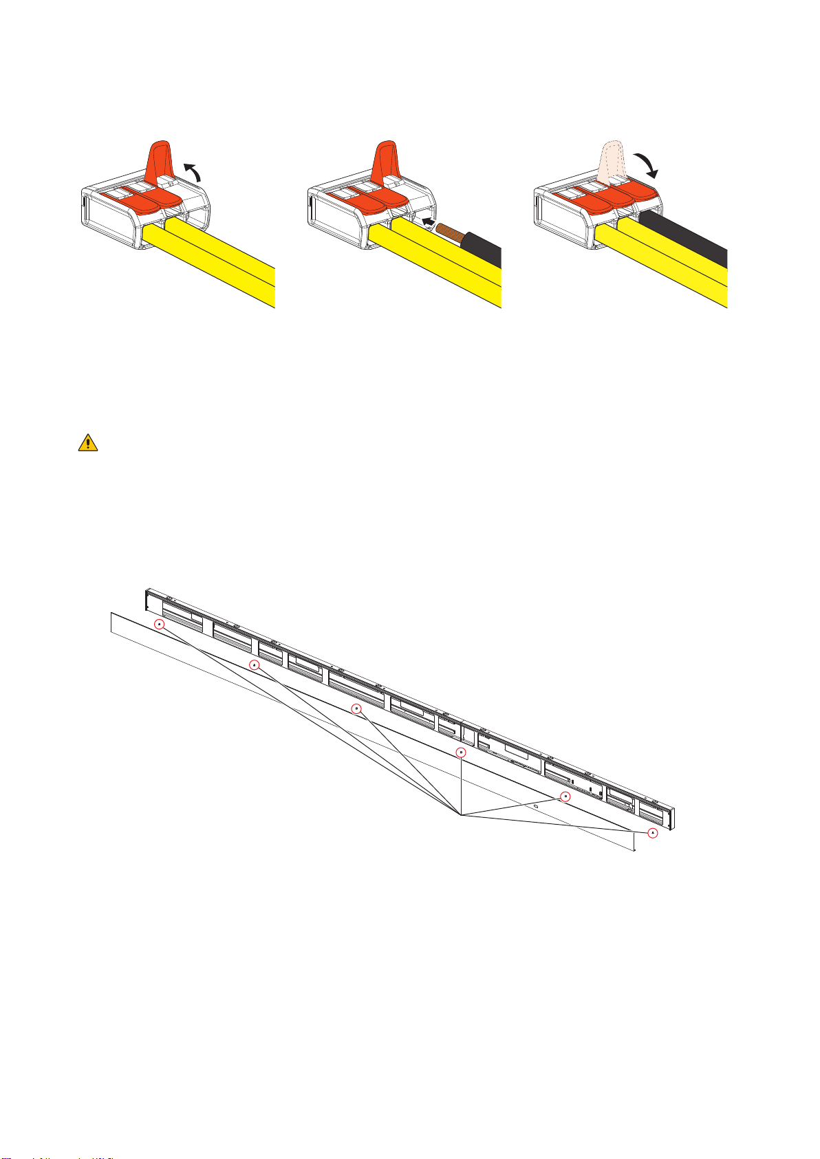
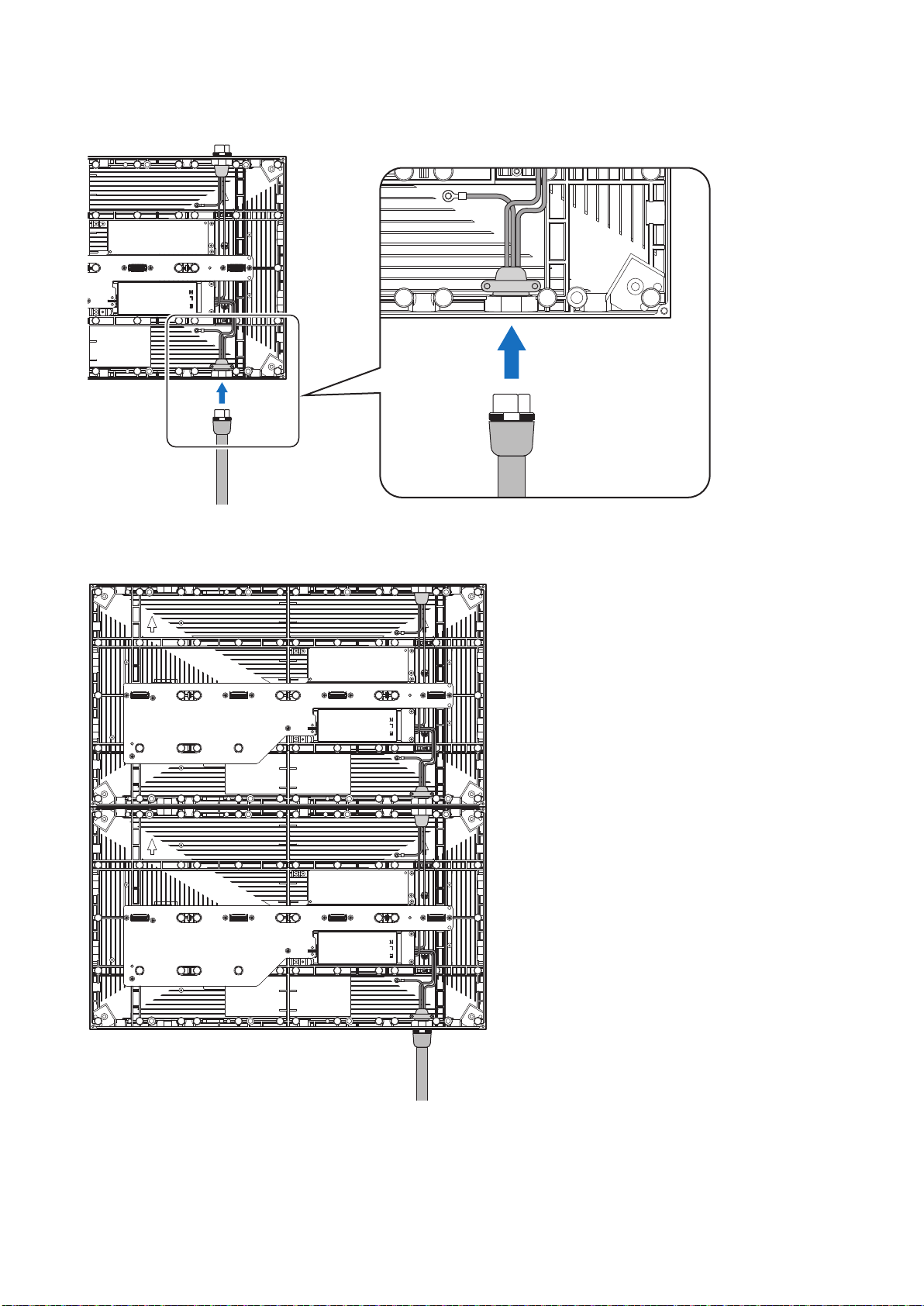
(1) Power cord connection
Connect the power cords to the LED modules on the rst row.
The power cord must be securely plugged.
Connect the power cords between the LED modules.
English - 25
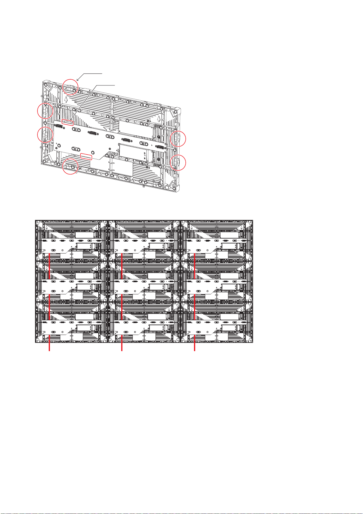
(2) LAN cable connection
Connect the LAN cables for the signal between the LED modules. Use the through holes to pass the cables
between the modules.
Six through holes for the LAN cables
LAN connectors
[Connection example 1] Connecting from bottom to top using multiple ports
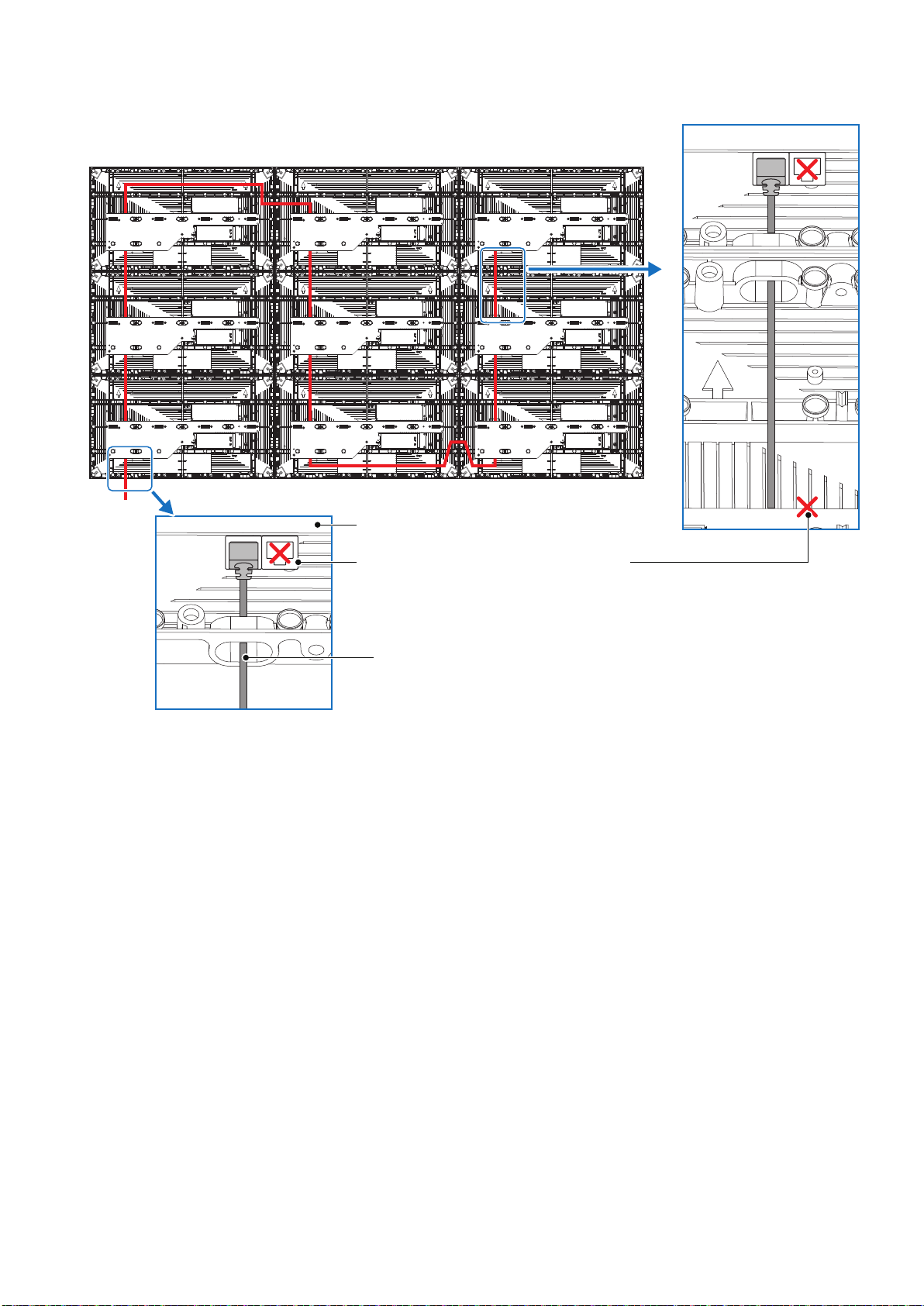
English - 26
[Connection example 2] Connecting all the LED modules using a single LAN cable
Hub board
Connect the cable to the LAN connector
on the left.
Do not use the LAN connector on the
right.
Insert the LAN cable into the through hole and connect it to
the LAN connector on the left.
LAN cable from the LED controller
English - 27
4. Installing the pixel card
CAUTION
• The pixel cards contain powerful magnets. If magnetic cards come close to the pixel cards, the data
contained within may be damaged. Therefore, do not carry any magnetic card when installing the pixel
cards.
• When installing the pixel cards, pay attention not to damage them against the pixel cards already installed
or other objects. Otherwise, the video may not be displayed properly.
• Take measures against static electricity when installing the pixel card. Do not touch the LED display areas
and the back of the pixel card.
• Check that the power supply to the LED modules is cut before starting the work.
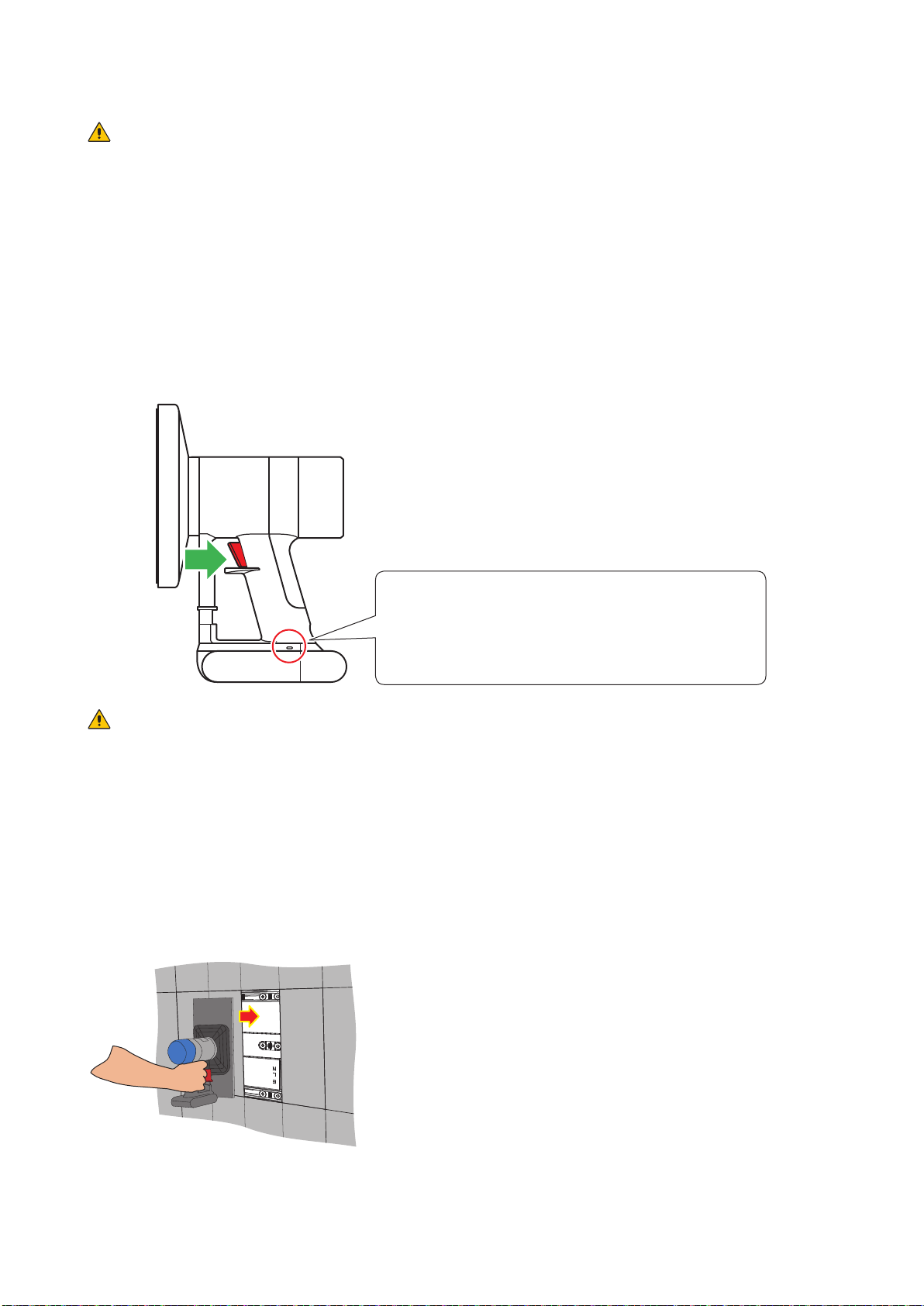
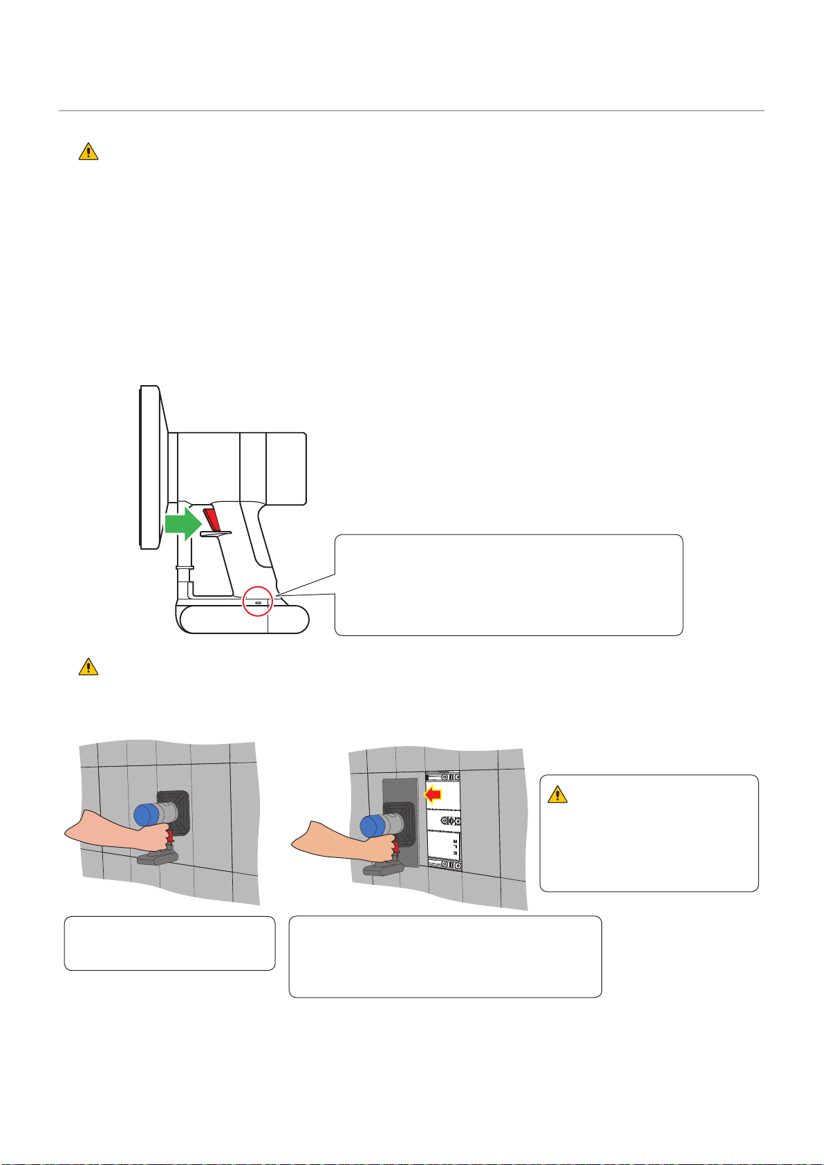
Install the pixel card using the maintenance tool.
Pull the trigger of the handle to activate the suction function. Release the trigger to stop the suction function.
Status display
- Lit blue: In operation
- Flashing blue: Battery is low.
Charge the tool using the AC adapter
supplied with the maintenance tool.
CAUTION
Check that the battery of the tool is fully charged before starting the work. The pixel card will fall if the
battery runs out. Lightly hold the pixel card with your hand to prevent it from falling.
(1) Push the maintenance tool against the pixel card without turning it on.
(2) Turn the maintenance tool on and then install the pixel card to the cabinet paying attention that the
arrows on the back of the pixel card and on the hub board are orientated toward the same direction,
and that the two guide pins of the pixel card are aligned to the guide holes of the cabinet (two for each
pixel card).
The pixel card is secured by the 14 magnets on each cabinet.
English - 28
Guide pin Guide hole
MagnetMagnet
(3) Check that the pixel card stays securely in place and then turn the maintenance tool off.
English - 29
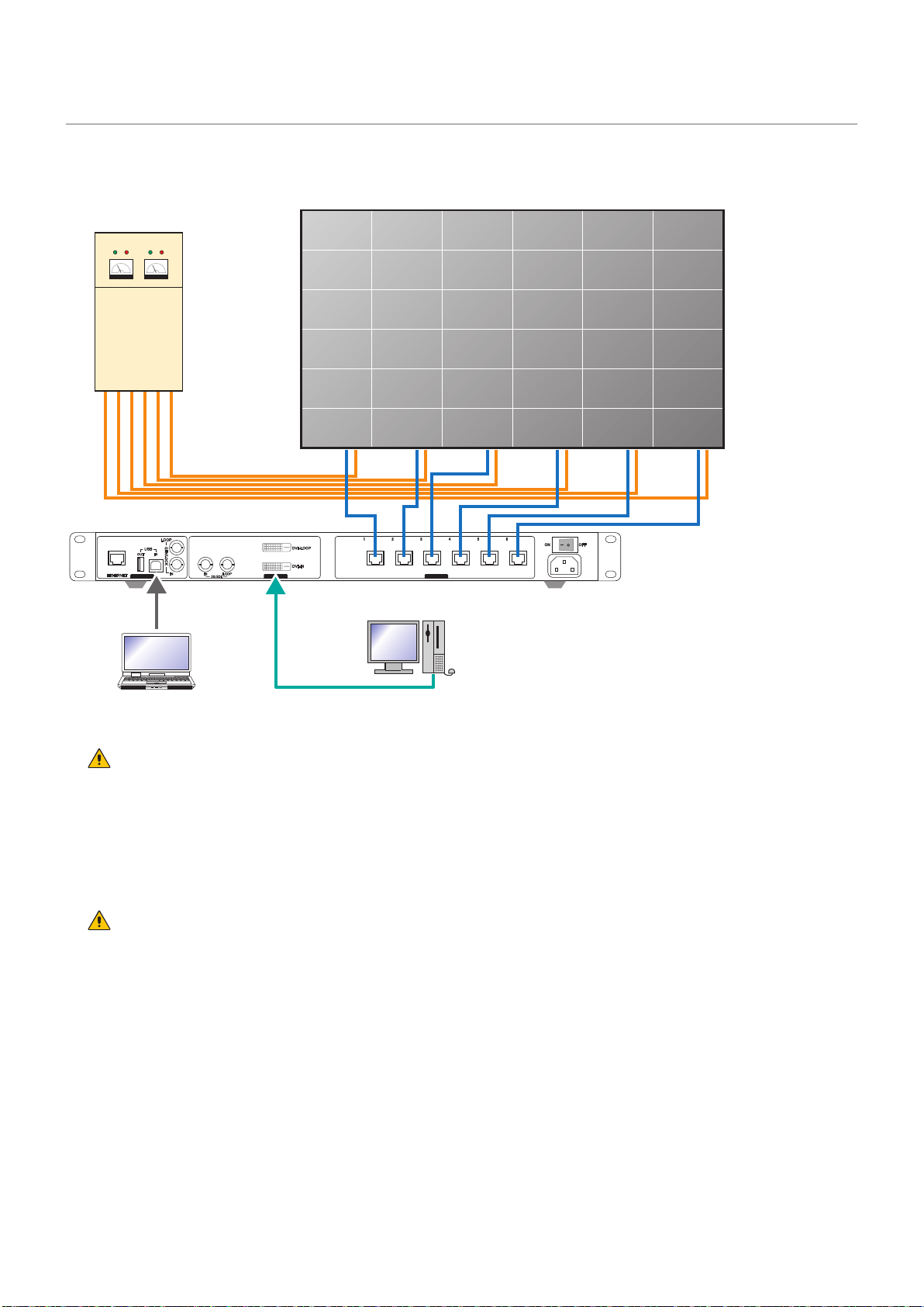
Screen Conguration
Check that all the connections are completed, and then turn on the LED modules and the LED
controller.
CONTROL INPUT OUTPUT
Power distributor
Video signalControl signal
LED controller
WARNING
Pay attention to the wire colors of the power cord when connecting the cord. If the cables are not connected
correctly, it may lead to a re or an electrical shock.
Blue (N)
Brown (L)
Yellow green (Ground)
CAUTION
When using LAN cables of 60 m to 100 m in length, the product may not operate correctly depending on the
quality of the cables. In such a case, it is recommended to use optical-ber cables.
Ask a technician or your retailer for more details.
English - 30
Setting the screen conguration
Perform the setting using the LCT-Mars control software by Novastar.
Log in with the administrator privileges.
Display the login screen as follows: User(U) → Advanced Synchronous System UserLogin(A).
Enter the password (“admin” by default) to log in with the administrator privileges.
To change the password, go to User(U) → Change Password(U) with the administrator privileges.
CAUTION
Do not forget the new password after it has been changed.
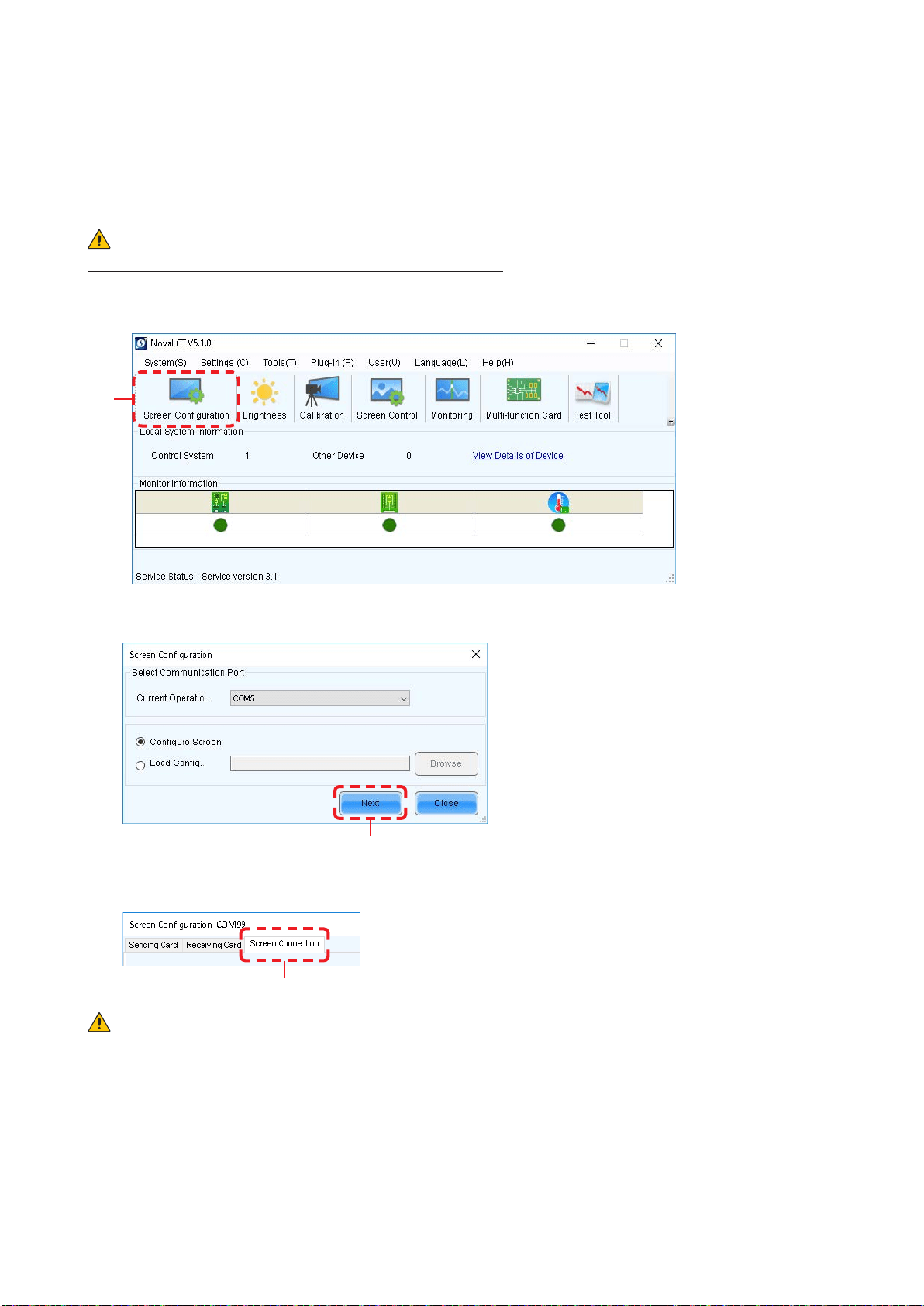
Click “Screen Conguration” (a).
(a)
Check the port in “Select Communication Port”, and then click the “Next” button (b).
(b)
In the Screen Conguration screen that is displayed, select the “Screen Connection” tab (c).
(c)
CAUTION
Do not change the settings in the “Receiving Card” tab.
Otherwise, the video may not be displayed properly.
English - 31
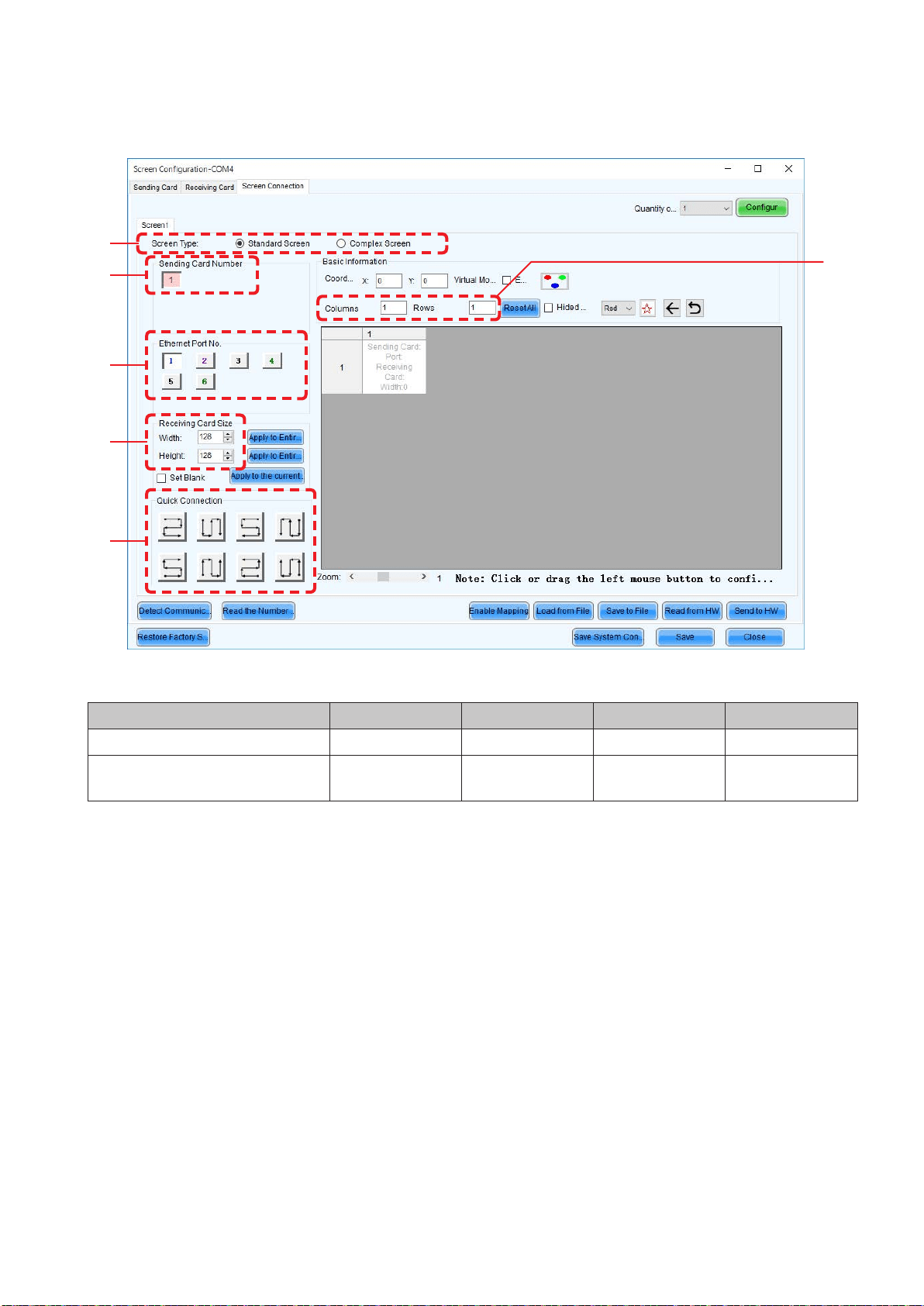
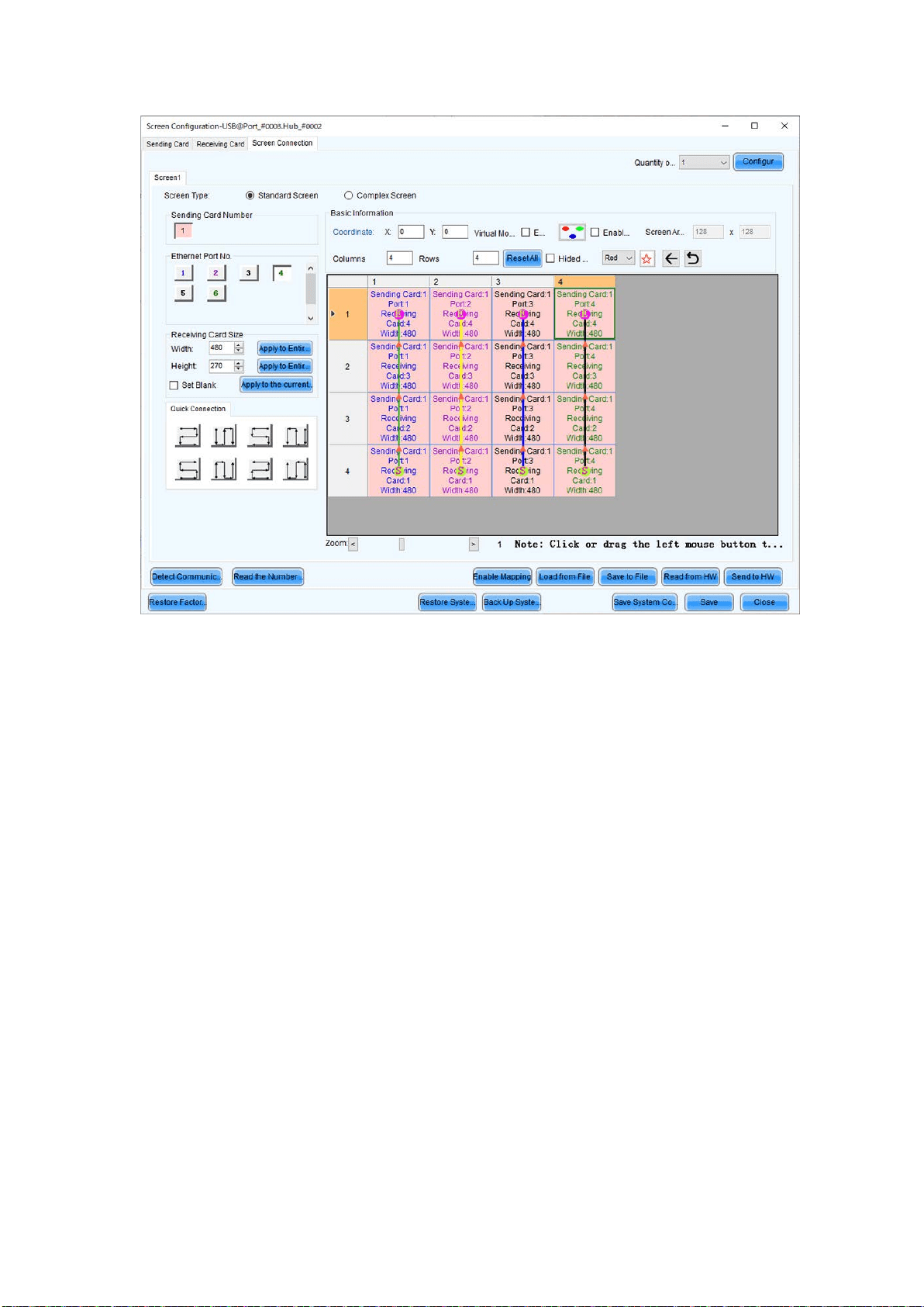
Select “Standard Screen” under “Screen Type” (d).
The settings in “Sending Card Number” (e) and “Ethernet Port No.” (f) vary depending on the
connected LED controller.
(d)
(e)
(h)
(f)
(g)
(i)
Enter the value in the table below under “Receiving Card Size” (g).
Product name LED-E012i LED-E015i LED-E018i LED-E025i
Pixel pitch 1.25 mm 1.56 mm 1.88 mm 2.50 mm
Number of displayed pixels
(resolution/module)
Width 480
Height 270
Width 384
Height 216
Width 320
Height 180
Width 240
Height 135
[Columns/Rows] Enter the number of installed screens under “Columns/Rows” (h) (the number of vertically
installed screens in Columns, and the number of horizontally installed screens in Rows).
English - 32
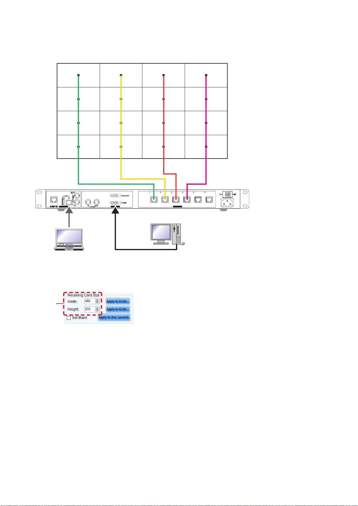
[Conguration example]
The setting values are given for the following example where 16 LED-E012i modules (pixel pitch of 1.25 mm)
are installed in a 4 (columns) x 4 (rows) conguration.
CONTROL INPUT OUTPUT
(1) With a pixel pitch of 1.25 mm, enter Width=480 and Height=270 under “Receiver Card Size” (g).
Do not use the buttons located next to the values.
(g)
English - 33
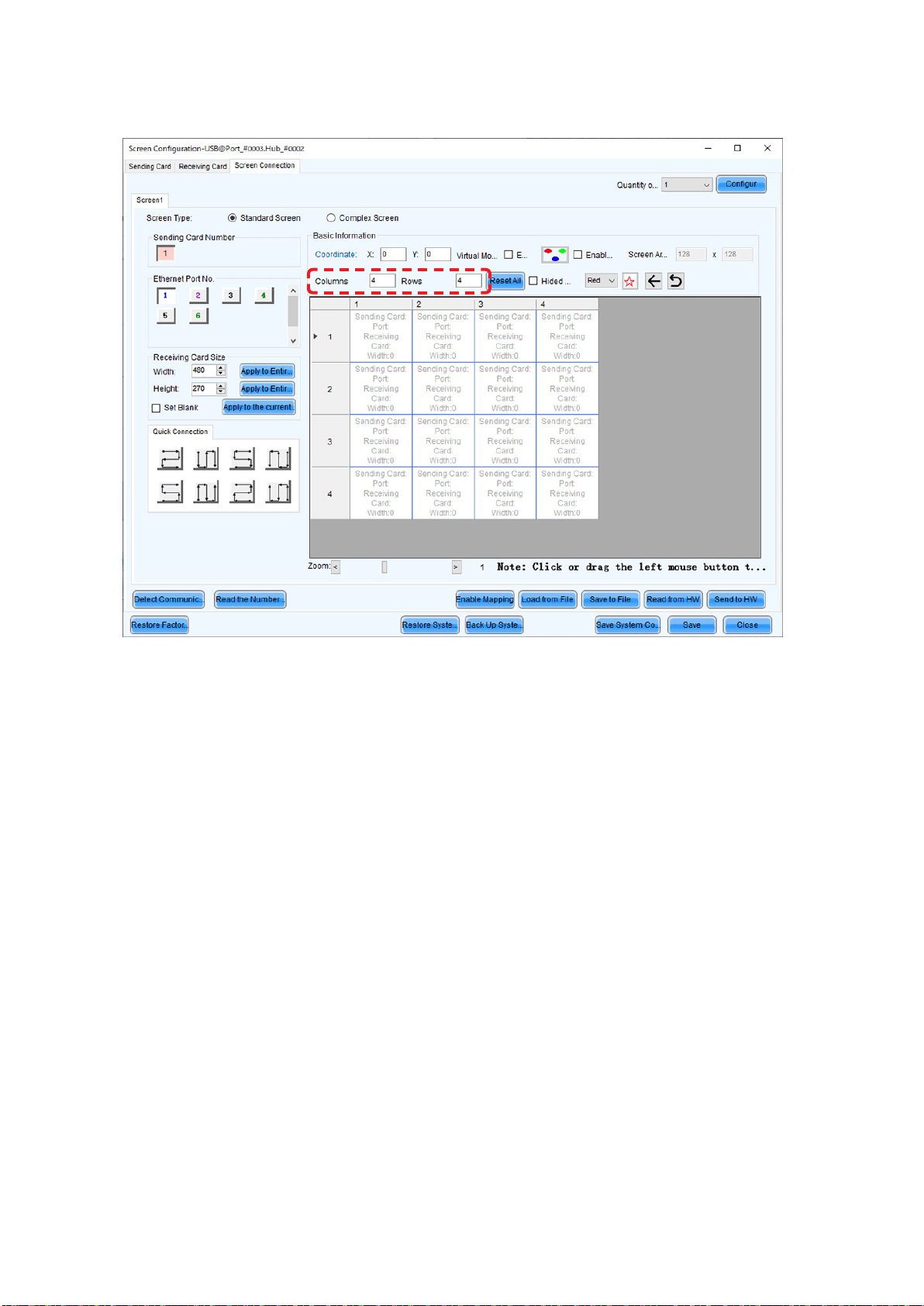
(2) Since the conguration is 4 (columns) x 4 (rows), enter Columns=4 and Rows=4. A 4 (columns) x 4
(rows) screen conguration is displayed.
English - 34
(3) If multiple LED controllers are used, select the number of the connected LED controllers.
Since only one controller is used in this example, it is not necessary to set “Sending Card Number” (e).
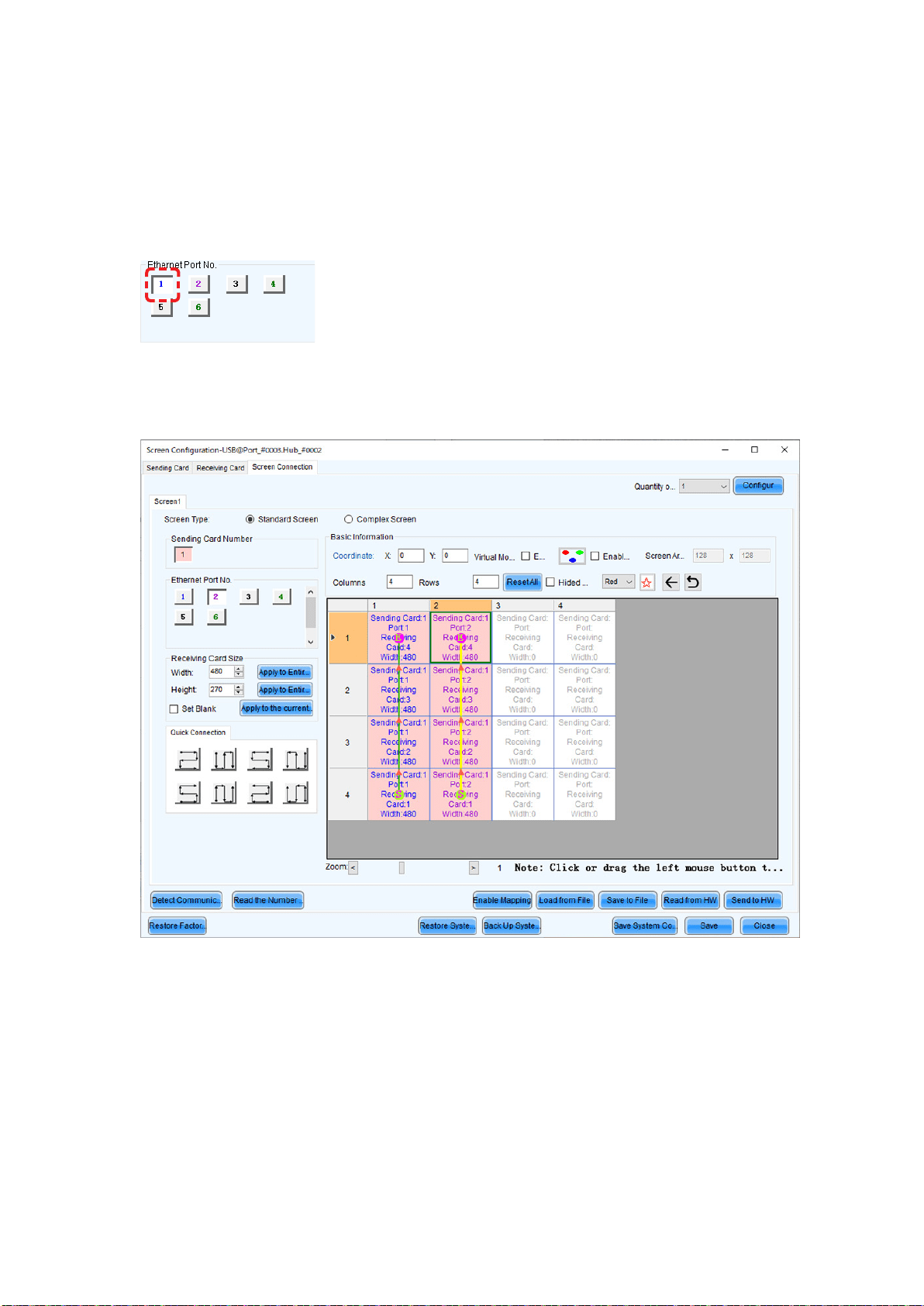
(4) Congure the connection.
(4)-1 Connecting from bottom to top using multiple ports
The system is connected to port 1 of the LED controller.
Select “1” (port 1) under “Ethernet Port No.” (f).
Select the cabinet at the bottom left with the mouse, and then select the other cabinets up to the top
cabinet.
Then select Port2 and select the cabinets from the bottom to the top as you did for Port1.
English - 35
Follow the same procedure for Port3 and Port4.
English - 36
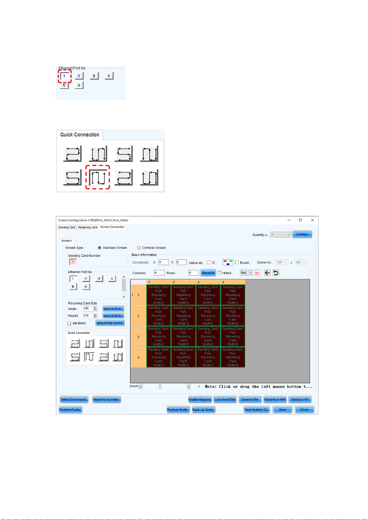
(4)-2 Connecting all the LED modules using a single LAN cable
The system is connected to port 1 of the LED controller.
Select “1” (port 1) under “Ethernet Port No.” (f).
Click (select) the connection pattern under “Quick Connection” (i). Since the modules are connected
from the bottom left to the top right in the example, the pattern is as shown in the gure.
Select all the cabinets from the top left to the bottom right as shown in the gure below.
English - 37
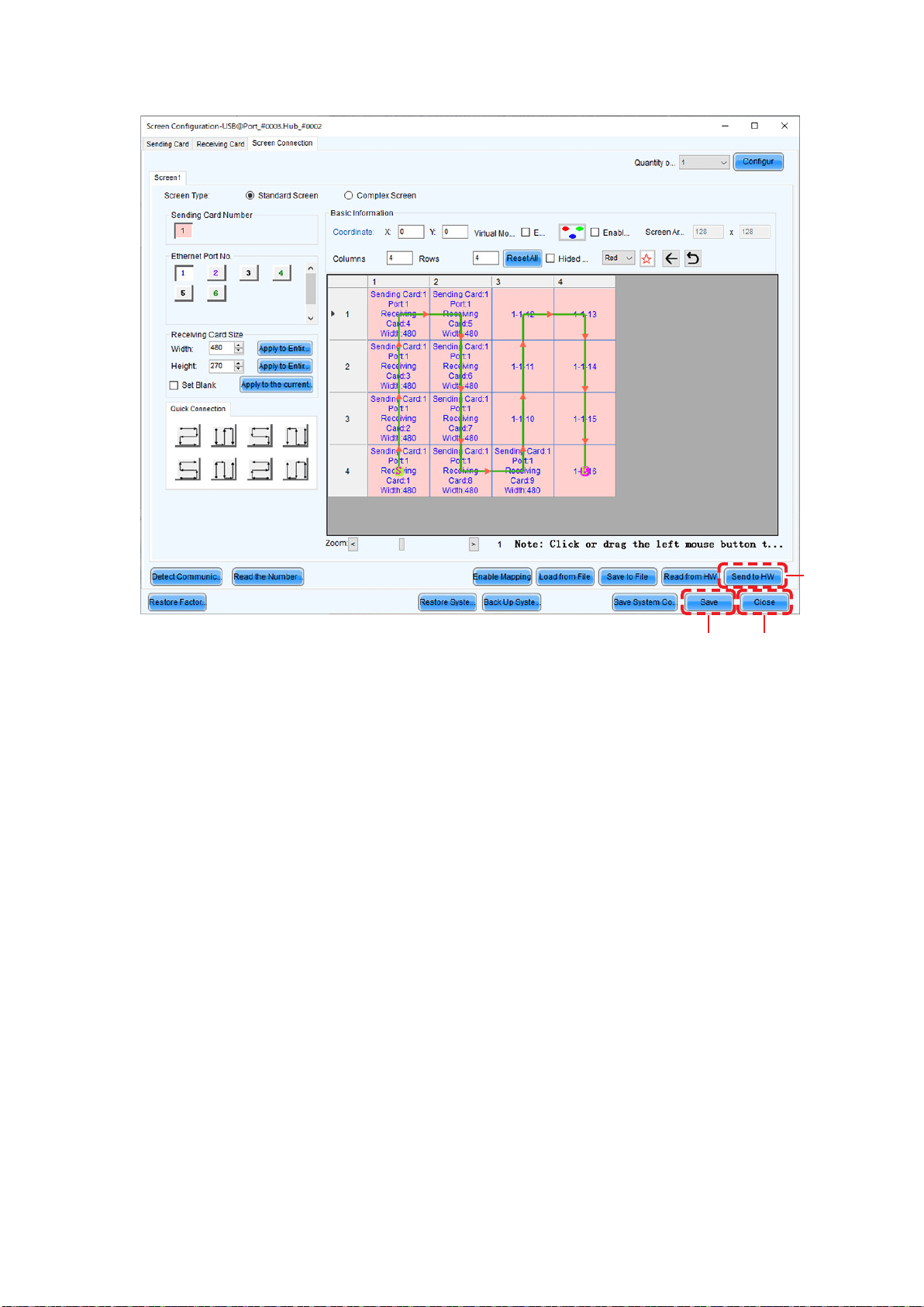
The selection is done automatically to obtain the screen below.
(k)
(j)
(l)
(5) Save the settings.
(a) Click the “Send to HW” button (j). When the dialog box indicating that the process nished
successfully is displayed, click OK.
(b) Check that the image is correctly displayed, and then click the “Save” button (k). When the screen
indicating that the process nished successfully is displayed, click OK.
The setting of the screen conguration is complete. Click the “Close” button (l) to close the Screen Conguration
screen.
English - 38
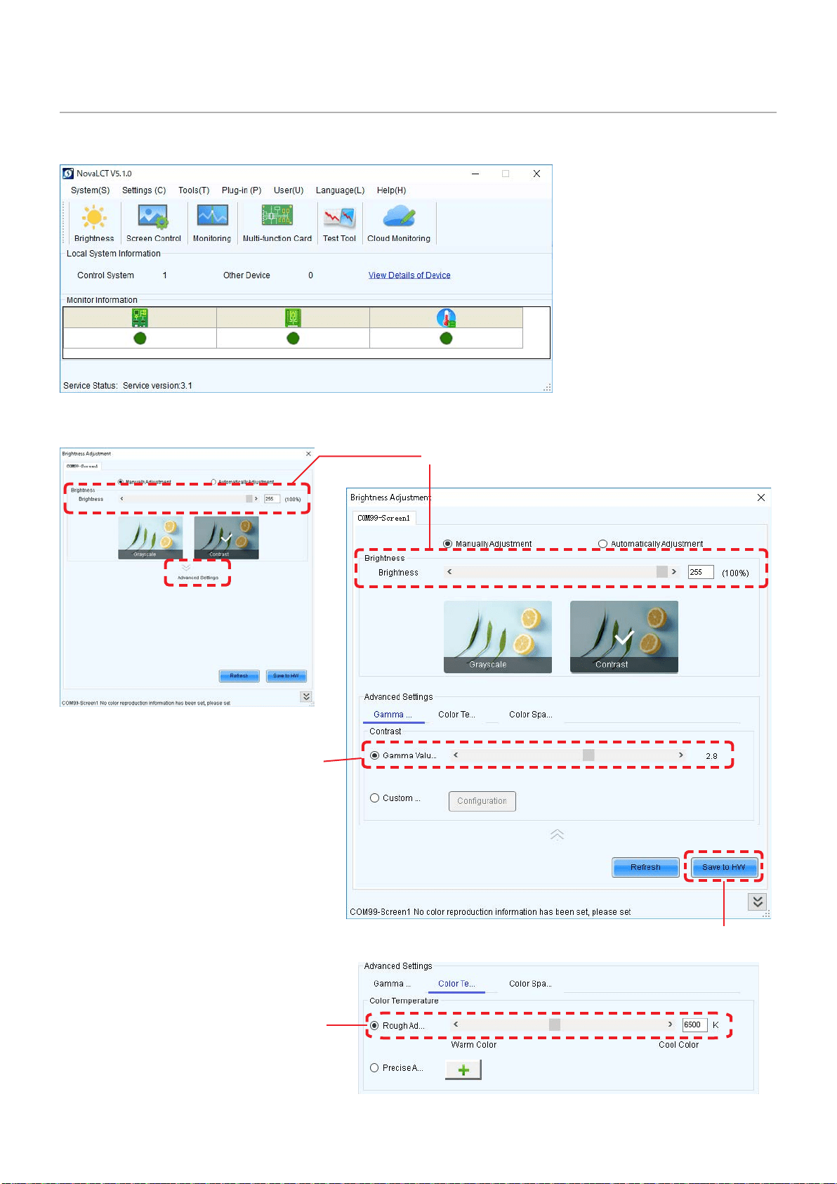
Image Setting
You can adjust the brightness, the gamma correction value, and the color temperature.
Click “Brightness” on the top screen to display the following window.
(e)
(c)
(b)
(d)
(a)
Click “Advanced Settings” to
expand the screen.

English - 39
Click “Advanced Settings” ( ) (a) to expand the setting screen.
(1) Brightness
Set the brightness of the screen using the slider (b).
Increasing the value increases the brightness.
(2) Gamma correction
Set the gamma correction value using the slider (c).
Increasing the value makes the dark parts of the screen darker.
(3) Color temperature
Set the color temperature using the slider (d).
Increasing the value makes the colors more bluish, while reducing the value makes the colors more
reddish.
When the setting is complete, click the “Save to HW” button to save the settings.
English - 40
Maintenance
CAUTION
• Disconnect the power supply to the LED modules when performing the maintenance.
• Use the correct screwdriver for the shape of the screws when removing (loosening) or setting (tightening)
the screws.
Pay attention not to drop the screws and the other parts you have removed.
Pay attention not to lose the removed screws since they will be reused.
Removing a pixel card
Remove the pixel card using the maintenance tool.
Pull the trigger of the handle to activate the suction function. Release the trigger to stop the suction
function.
Status display
- Lit blue: In operation
- Flashing blue: Battery is low.
Charge the tool using the AC adapter
supplied with the maintenance tool.
CAUTION:
Check that the battery of the maintenance tool is fully charged before starting the work. Pixel card falls if the
battery runs out. Hold the pixel card with your hand to support in case it falls.
(1) Push the maintenance tool
against the pixel card without
turning it on.
(2) Turn the maintenance tool on, and then pull it
straight toward you to remove the pixel card.
Keep the maintenance tool turned on.
(3) Hold the pixel card, and then turn the
maintenance tool off.
CAUTION:
Do not turn the maintenance
tool off until you hold the pixel
card.
Otherwise, the pixel card may
fall and break.
English - 41
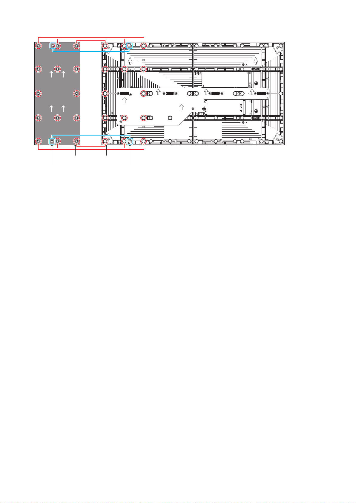
Removing the power supply
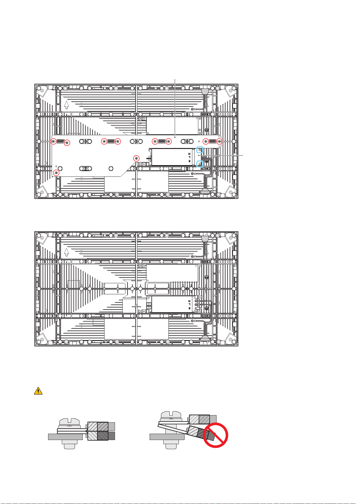
Disconnect the LAN cable connected to the hub board.
Remove the 10 screws securing the hub board, and then remove the hub board. Then, remove the
two screws securing the terminal cover.
Hub board
Terminal cover
Disconnect the power cables connected to the power supply and remove the two screws securing the
power supply, and then remove the power supply.
The power supply installation is done by following the same procedure in the reverser order.
Apply some thermal paste on the back of the power unit you will install before installing it. Ask your
retailer for more details on the types of thermal paste.
CAUTION:
When attaching two cables with one screw, place the ring terminals of the cables back to back.
OK NG
English - 42
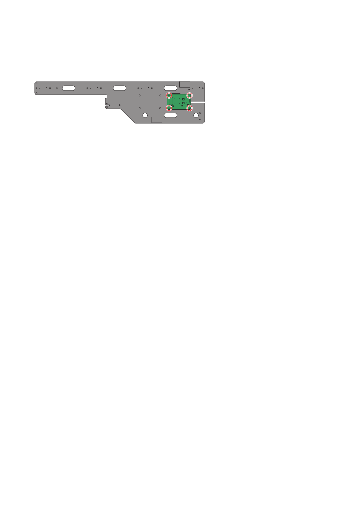
Removing the receiving card
Remove the receiving card from the hub board.
Remove the four screws securing the receiving card, and then remove the receiving card from the
hub board.
Receiving card
English - 43
Troubleshooting
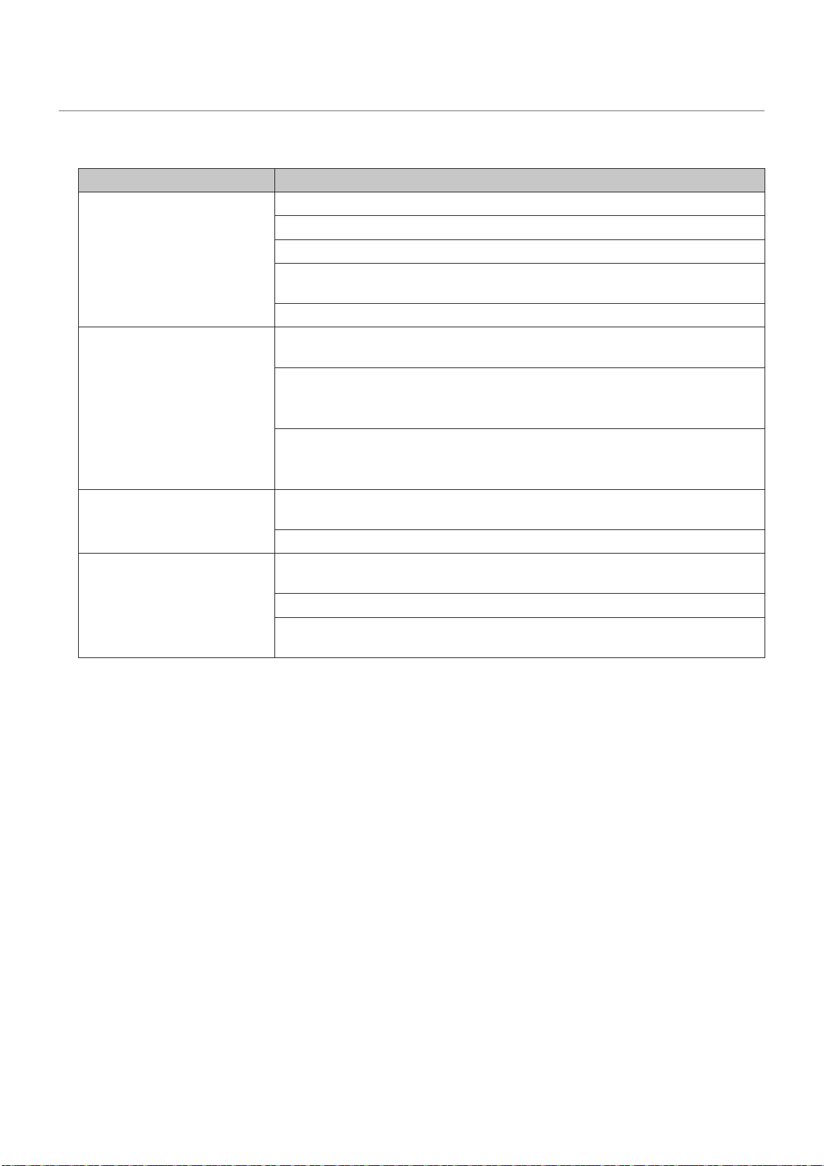
1. Display problems
Problem Solution
Nothing is displayed on
all the LED modules.
Check that power is being supplied to the LED modules.
Check that the LED controller is turned on.
Check that a video signal is being input to the LED controller.
Check that a LAN cable is correctly connected between the LED
controller and the LED module.
Check that the brightness is not set to 0% (= not lit).
Nothing is displayed on
one LED module.
Check that a LAN cable is correctly connected between the LED
controller and the LED module.
The receiving card inside the LED module may be broken.
→ Check the status of the LED module by following the procedure
in the next section “2 State monitoring using the software”.
The power unit inside the LED module may be broken.
→ Check the status of the LED module by following the procedure
in the next section “2 State monitoring using the software”.
No image is displayed on
one pixel card.
Check that the contacts of the pixel card are correct (contacts of
the hub board).
The pixel card may be broken. Replace it with a spare pixel card.
Control (communication)
is not possible.
Check that the communication cable is correctly connected between
the computer and the LED controller.
Check that the LED controller is turned on.
If the communication cable is a USB cable, check that the device
driver runs correctly.
English - 44
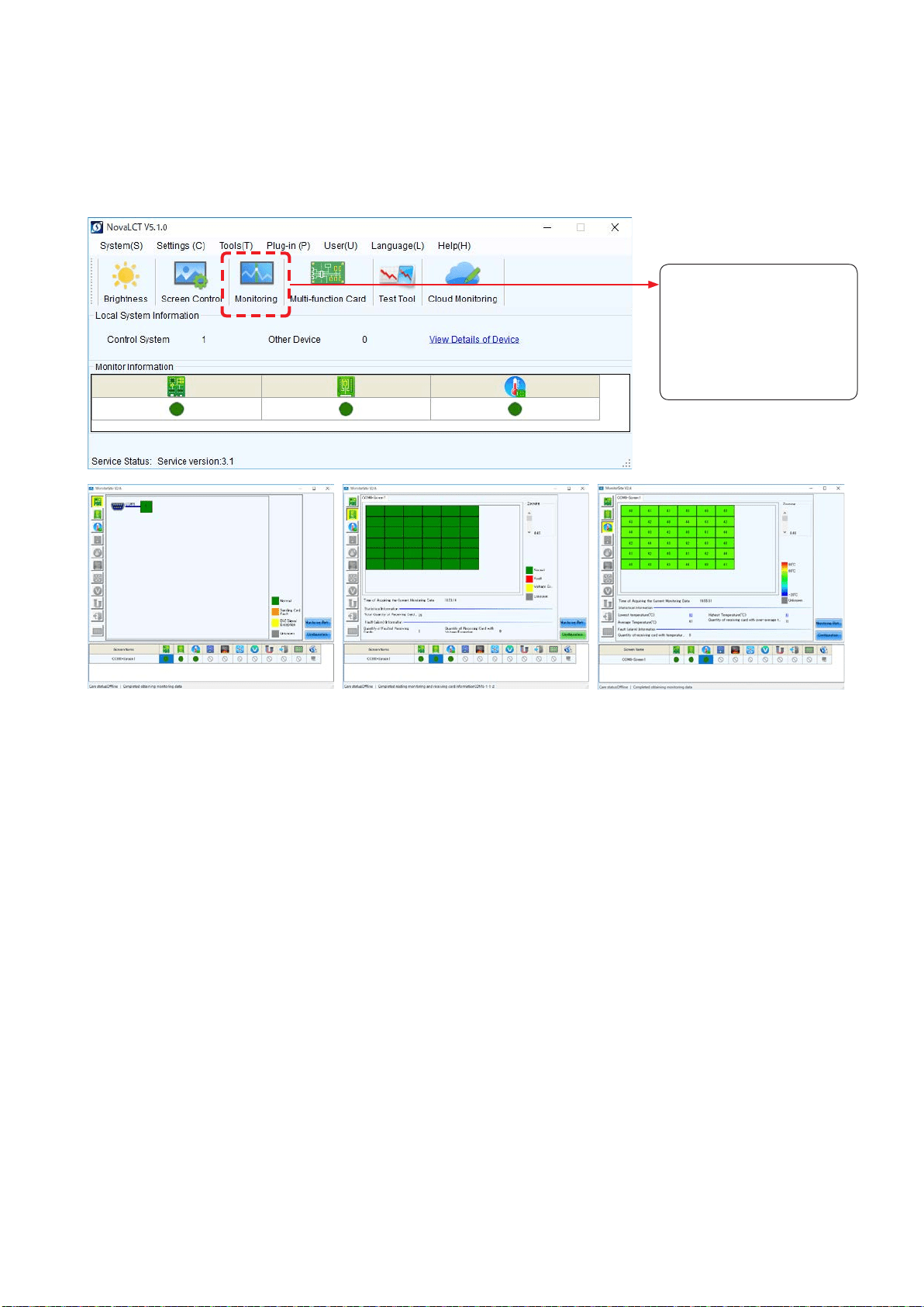
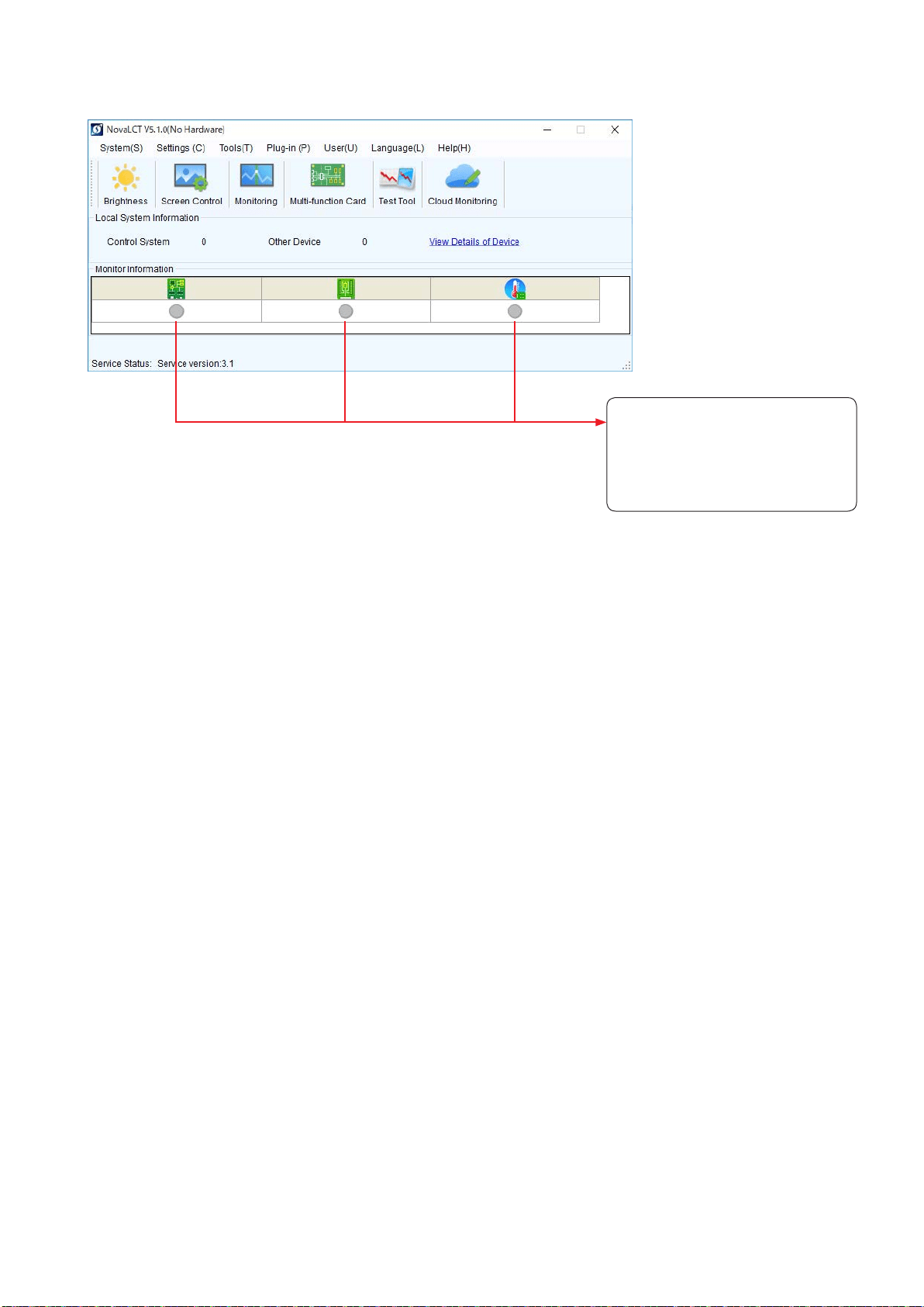
2. State monitoring using the software
In case of a problem, you will be able to determine the location where it occurred by monitoring the state of
the system.
2-1 Display under normal conditions
The display is green under normal conditions.
Click “Monitoring” to check
- the state of the LED
controller
- the operating state of the
LED modules
- the temperature of the
LED modules
State of the LED controller State of the LED modules Temperature of the LED modules
English - 45
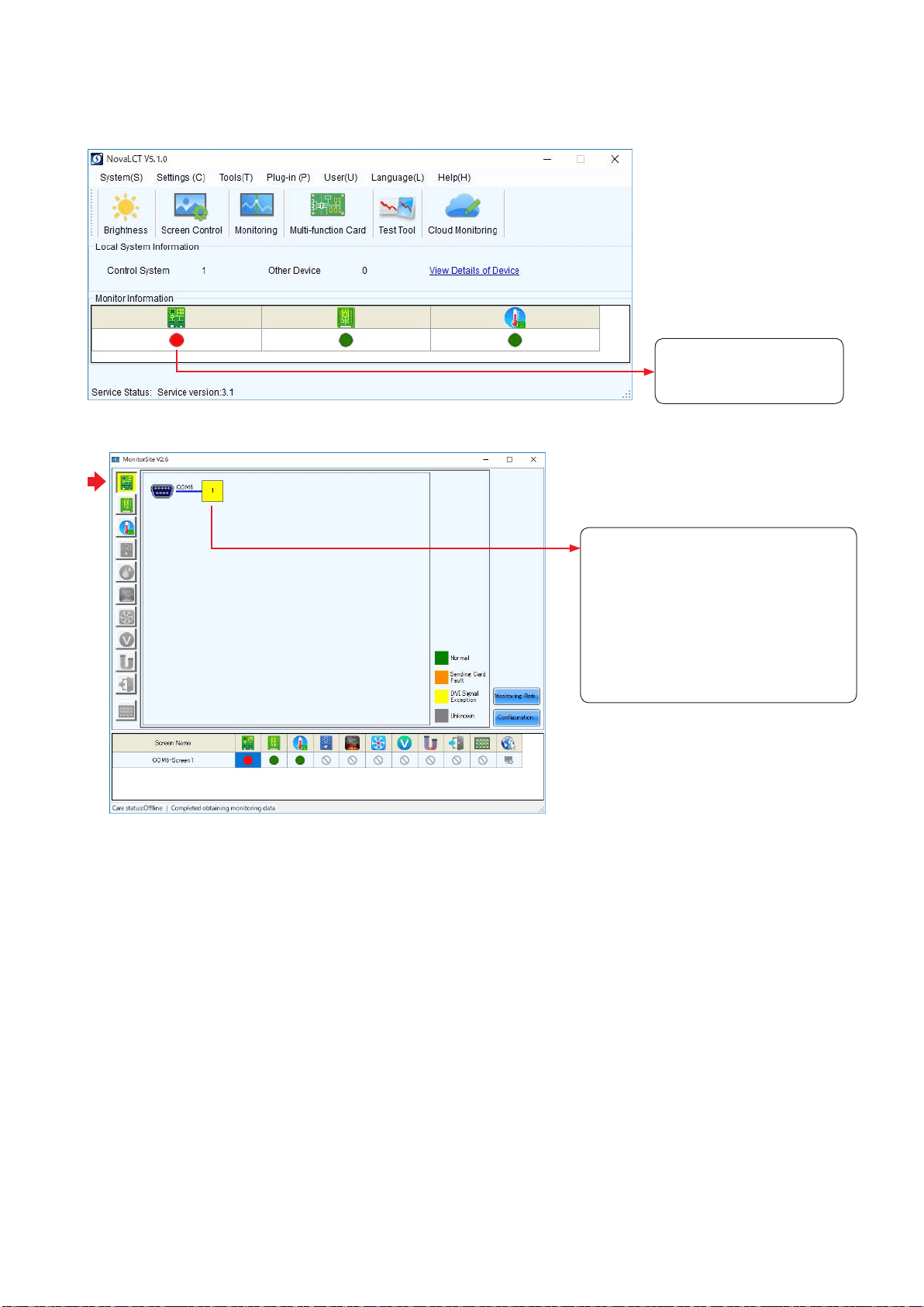
2-2 Display under abnormal conditions
(1) Problem with the input signal to the LED controller
When the display is red,
there is a problem with the
LED controller.
To display more details, click “Monitoring”, and then click “Sending card” on the screen that is displayed.
No video signal is being input to the LED
controller.
- Check that the LAN cable is
connected.
- Check that a video signal is being
output from the video output
equipment.
- If multiple signals are being input to
the LED controller, check the input
settings of the LED controller.
English - 46
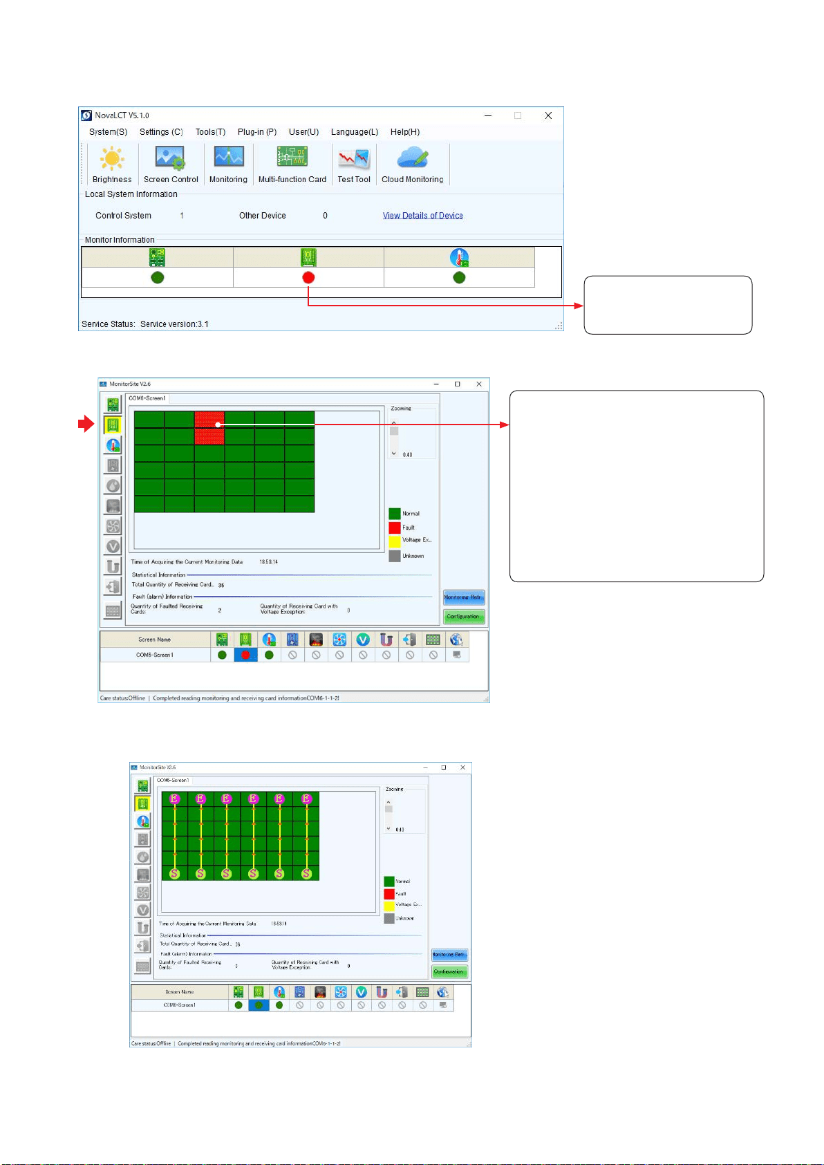
(2) Problem with the LED modules
When the display is red,
there is a problem with the
LED module operation.
To display more details, click “Monitoring”, and then click “Receiving card” on the screen that is displayed.
In the example shown on the left, the
following problems must be considered.
- Signal loss between the screen of the
1st row 3rd column and the screen of
the 1st row 2nd column
→ Check the LAN cable.
- Problem with the power unit of the
screen of the 1st row 2nd column
- Problem with the receiving card of the
screen of the 1st row 2nd column.
→ Check that the receiving card is
securely connected.
With the connection shown in the gure below.
English - 47
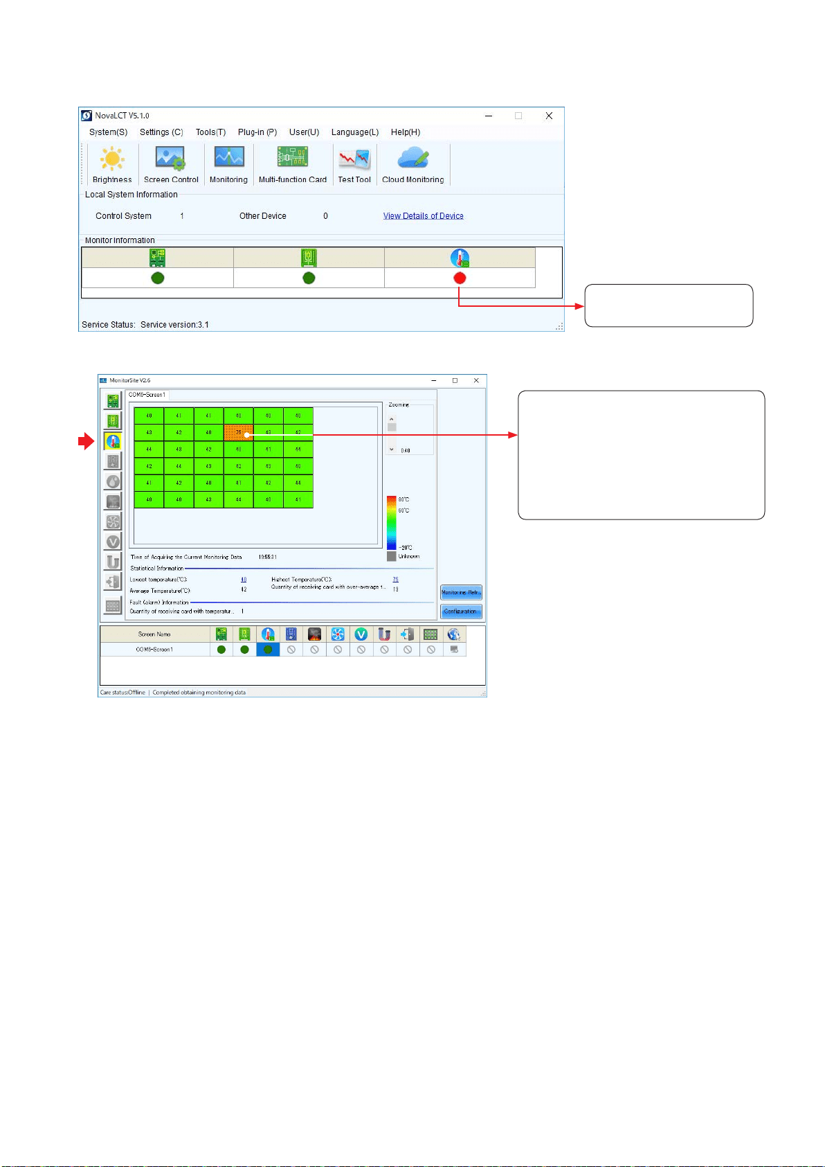
(3) Problem with the internal temperature of the LED modules
There is a problem with
the LED module operation.
To display more details, click “Monitoring”, and then click “Temperature” on the screen that is displayed.
The LED modules with a high
temperature are displayed in warm
colors.
Since the internal temperature is high,
decrease the brightness setting.
If changing the brightness setting could
not solve the problem, contact your
retailer or the Customer Service.
English - 48
(4) Communication problem
When the display is grey, the
communication is not established.
→ Check that the USB cable is
connected.
→ Check that the LED controller is
turned on.
English - 49
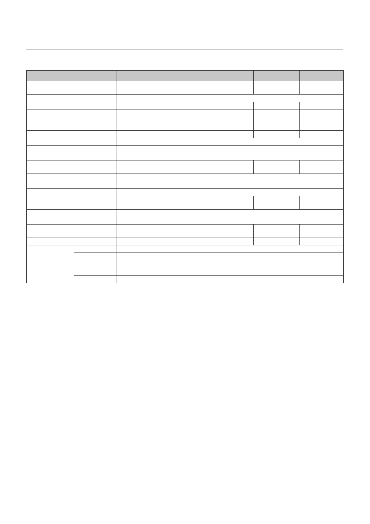
Specications
Models for indoor use
LED-E012i-108 LED-E015i-135 LED-E018i-162 LED-E025i-217 LED-E012i-217
Module LED-E012i
4x4
LED-E015i
5x5
LED-E018i
6x6
LED-E025i
8x8
LED-E012i
8x8
LED conguration 3-in-1 SMD
Pixel pitch 1.25 mm 1.56 mm 1.88 mm 2.50 mm 1.25 mm
Number of displayed pixels
(resolution/module)
1920 × 1080 1920 × 1080 1920 × 1080 1920 × 1080 3840 × 2160
Brightness 600 cd/m
2
600 cd/m
2
800 cd/m
2
1000 cd/m
2
600 cd/m
2
Contrast ratio 5000:1 4000:1 5000:1 7000:1 5000:1
Brightness adjustment range 0 to 100% (256 increments)
Gamma correction 1.0 to 4.0 (default setting: 2.8)
Color temperature 3000 K to 9500 K (default setting: 6500 K)
Viewing angle
Up 80°, Down 80°,
Left 85°, Right 85°
Up 70°, Down 70°,
Left 70°, Right 70°
Up 70°, Down 70°,
Left 70°, Right 70°
Up 80°, Down 75°,
Left 80°, Right 80°
Up 80°, Down 80°,
Left 85°, Right 85°
Signal interface Signal input 1 × RJ-45
Signal output 1 × RJ-45
Power supply 100 V AC to 240 V AC, 50 Hz/60 Hz
Power consumption
(all white, 100% brightness)
2000 W 3125 W 4500 W 8000 W 8000 W
Ingress protection Front IP 20 / Back IP 20
Maintenance Front
Dimensions 2412 × 1456 ×
50 mm
3012 × 1793.5
× 50 mm
3612 × 2131 ×
50 mm
4812 × 2806 ×
50 mm
4812 × 2806 ×
50 mm
Weight 89.2 kg 134.5 kg 189.2 kg 342.8 kg 342.8 kg
Operating
environment
Temperature -20 to 40°C
Humidity 10% to 80% (without condensation)
Altitude No more than 5000 m
Storage
environment
Temperature -20 to 45°C
Humidity 10% to 85% (without condensation)
Specications are subject to change without notice.
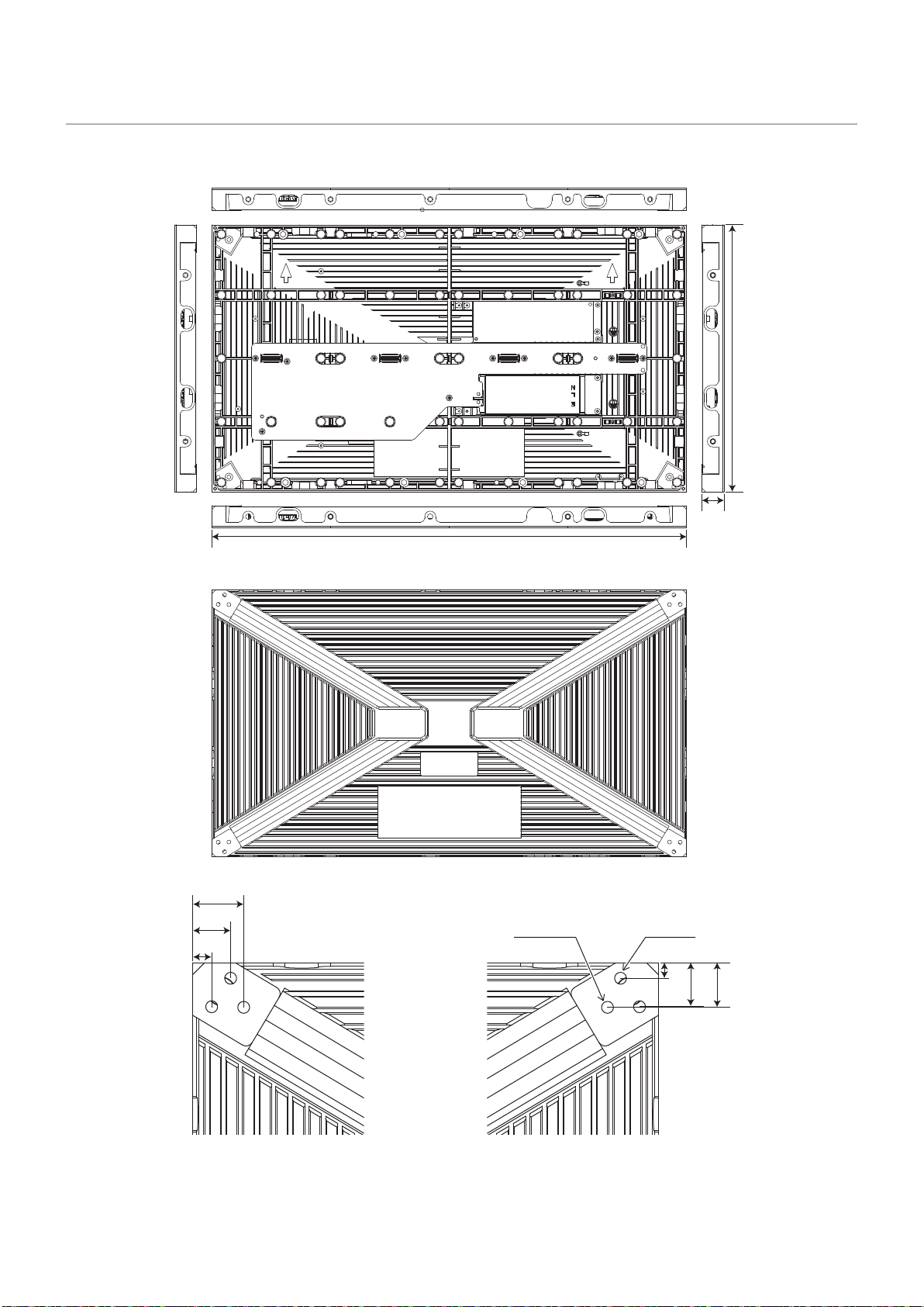
English - 50
Diagram
LED-E012i / LED-E015i / LED-E018i / LED-E025i
600
29
337.5
4-M5 8-M5
43.0
32.0
16.0
13.0
37.0
37.5
(Unit: mm)
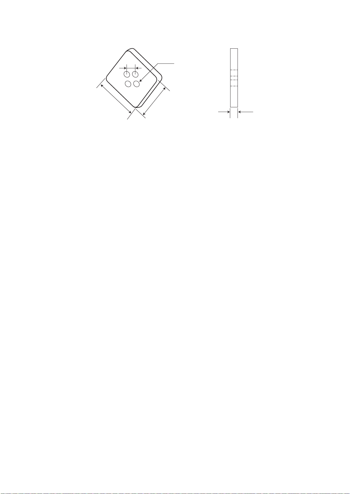
English - 51
LED-E012i / LED-E015i / LED-E018i / LED-E025i Cabinet alignment bracket
6
35
35
8
4-Φ5
(Unit: mm)