Loading ...
Loading ...
Loading ...

9
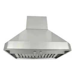
CH00 SERIES – STAND ALONE INSTALLATION
***This installation required to have Duct Cover
Model No. CH0030DC-12 / CH0036DC-12 / CH0042DC-12 / CH0048DC-12
Preparation before Installation
NOTE: TO AVOID DAMAGE TO YOUR HOOD,
PREVENT DEBRIS FROM ENTERING
THE VENT OPENING.
Decide the location of the venting pipe from the
hood to the outside. Refer to Figure 9.
A straight, short venting run will allow the hood
to perform more efficiently.
Try to avoid as many transitions, elbows, and
long run as possible. This may reduce the
performance of the hood.
Temporarily wire the hood to test for proper
operation before installing.
Important: Peel protective film off the hood
and the duct cover (if any).
If necessary, prepare back wall frame with cross
framing lumber for secure installation.
Using references on Table 2 and measurements
on page 21-22, decide the level of the lumber.
Refer to Figure 10.
Preparation before Installation
CAUTION: If required to move the cooking
range to install the hood, turn off the power on
an electric range at the main electrical box.
SHUT OFF THE GAS BEFORE MOVING A GAS
RANGE.
1. (This step only applies to 42” and 48” models.)
Attach exhaust plate on hood with four (3/16” x
3/8”) screws (included). Shown in Figure 11.
2. If necessary, remove the rubber stand on the
back of the hood.
3. Use twelve (3/16” x 3/8”) screws (included) to
attach the two hood-mounting brackets
(included) to the top of the hood.
4. Using references in Table 2 and Measurements
and Diagrams on pages 21-22, mark the leveling
point of the hood. Position six mounting screws
(included) on the wall, leaving 1/8” away from the
wall.
Figure 9
Figure 10
Figure 11
Loading ...
Loading ...
Loading ...