Loading ...
Loading ...
Loading ...
1413
MANUAL SHUT-OFF VALVE
• This valve is not shipped with the appliance and must be provided by the
installer.
• The manual shut-off valve must be installed in the gas service line between the
gas hook-up on the wall and the appliance inlet, in position where it can be
reached quickly in the event of an emergency.
• In Massachusetts: A T handle type manual gas shut-off valve must be installed in
the gas supply line to this appliance.
FLEXIBLE CONNECTIONS
• In case of installation with flexible couplings and/or quick-disconnect fittings,
the installer must use a heavy duty, AGA design-certified commercial flexible
connector of at least 1/2˝ (1.3cm) IF NPT (with a suitable strain relief in
compliance with ANSI Z21.41 and Z21.69 standards.
• In Massachusetts: The unit must be installed with a 36˝ (3 foot long) flexible gas
connector.
• In Canada: Use CAN 1-6. 10-88 metal connectors for gas appliances and
CAN 1-6.9 M79 quick disconnect device for use with gas fuel.
PRESSURE TEST POINT STOPPER VALVE
To avoid gas leaks, the pressure test-point stopper valve and gasket supplied with the
range is installed on the gas fitting at the back of the range according to the diagram
below.
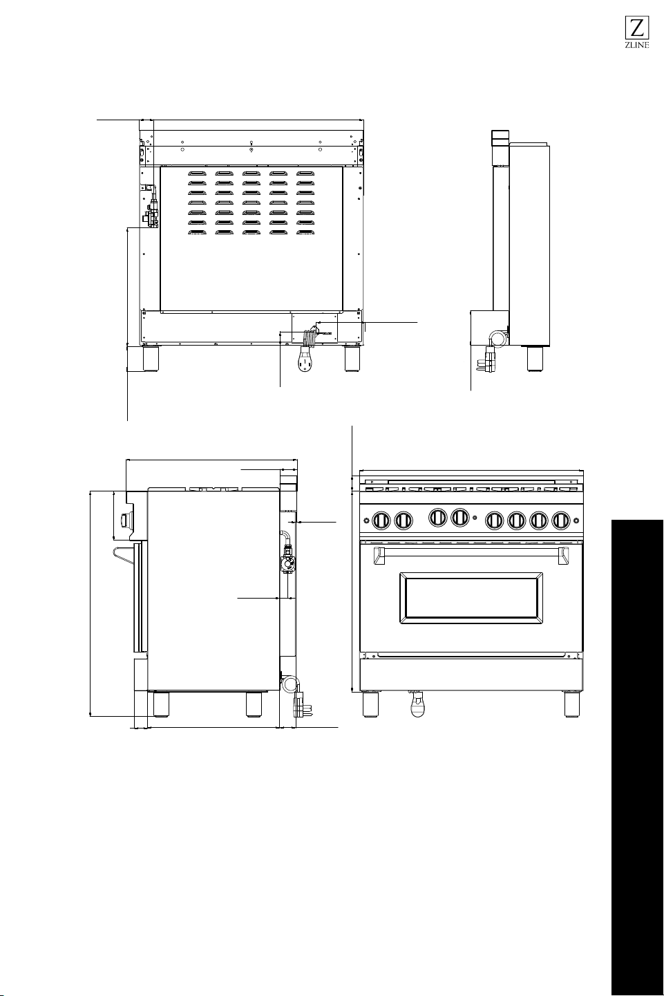
INSTALLATION
Gas Connection
Gas pipe
Gasket
Gas connection adaptor 1/2” NPT with
pressure test point 1/8” NPT (to be fixed
toward external side of the appliance)
Pressure test-point stopper
PRESSURE REGULATOR
Since service pressure may fluctuate with local demand, every gas cooking
appliance must be equipped with a pressure regulator on the incoming service line
for safe and efficient operation.
• The pressure regulator shipped with the appliance has two female threads 1/2”
NPT. The regulator shall be installed properly in order to be accessible when the
appliance is installed in its final position.
• Manifold pressure should be checked with a manometer and comply with the
values indicated below.
Natural Gas->4.0”W.c.P
L P/Propane-> 10.0” W.c.P
• Incoming line pressure upstream from the regulator must be 1˝ W.C.P. higher
than the manifold pressure in order to check the regulator.
• The regulator used on this range can withstand a maximum input pressure of 1/2
PSI (13.8˝ W.C or 3.5kPa) If the line pressure exceeds that amount, a step down
regulator is required.
• The appliance, its individual shut-off valve, and the pressure regulator must be
disconnected from the gas line during any pressure testing of that system at
pressures in excess of 1/2 PSI (13.8˝ W.c or 3.5kPa).
Pressure Regulator
Before carrying out this operation, disconnect the appliance from gas
and electricity.
Gas conversion shall be conducted by a factory-trained professional.
WARNING
INSTALLATION
Gas Connection
Gas Connection
Gas Connection
Loading ...
Loading ...
Loading ...