Loading ...
Loading ...
Loading ...
Rinnai 22 EHPA_VMA Series 2 Heat Pump OIM
OPERATION SEQUENCE OF CONTROLLER
When the power supply turns on, the heat pump control system initiates and will check the unit’s operating
parameters. The controller will check on all sensors, pressure switches and also main voltage. If conditions are
suitable (i.e All reading within the reasonable range) and there is enough energy available in the surrounding air,
the fan, circulating pump and compressor will turn on. If not enough energy is detected in ambient air then the
controller calls for the booster heating element to run.
There will be a delay of approximately 2 minutes from the time the main power is switched on before the pump, fan
and compressor begin operating.
The unit is self regulating so there are no internal adjustments to be made during commissioning. When the unit is
operated for the rst time, it runs through an initial heat up cycle, allow time for the initial heat up cycle. Depending
on the ambient conditions this can take several hours.
Once its rst heat up cycle is complete, empty approximately 60 litres of hot water from the tank through the PTR
valve outlet then allow the water in the tank to re-heat. Once the re-heat cycle is completed measure the water
temperature at the PTR outlet again. The temperature will be approximately 60º C.
If for any reason the unit does not start, the water is cold and the controller unit is not displaying any LED lights, an
electrician should test that power is available to the heat pump.
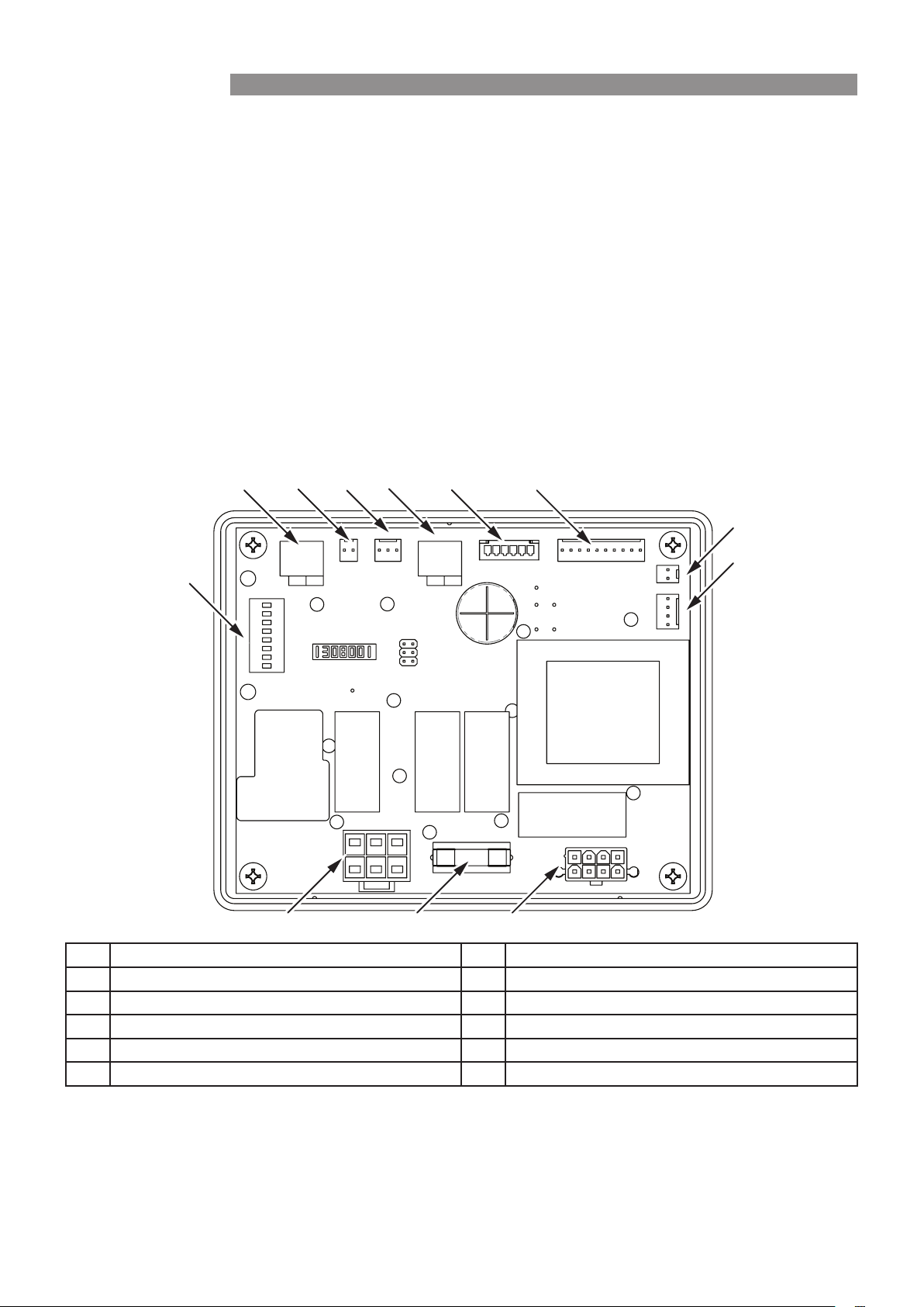
1 DIP Switch Test & Conguration 7 LED Display / Control Panel Output
2 Tank Temperature Sensor 8 Programming Serial Port (Wi-Fi)
3 Compressor Discharge Temperature Sensor 9 HMI (Accessory for service) Port
4 Fan Coil (Evaporator) Temperature Sensor 10 Compressor, Element , Main Power
5 High Pressure Switch 11 2 Amp Fuse
6 EEV Output (Electric Expansion Valve) 12 Fan, Pump, Defrost Power
1
2 3 4 5 6 7
8
9
10 11 12
INSTALLATION
Loading ...
Loading ...