Loading ...
Loading ...
Loading ...
27
bromic.com/heat
NOTES:
- Supply connection must be protected with appropriate safety device, that includes iso-
lation switch.
- Suitable junction box for connection to be supplied by installer.
- Control must be located in an environment of no more than 30°C ambient, away from
other heat sources and separation clearances maintained.
- Wiring must be completed according to local electrical code.
- 24V DC lighting circuit is to be separated inside the junction box from 220-240VAC
circuits.
- Electrical installation must ensure earth continuity is checked.
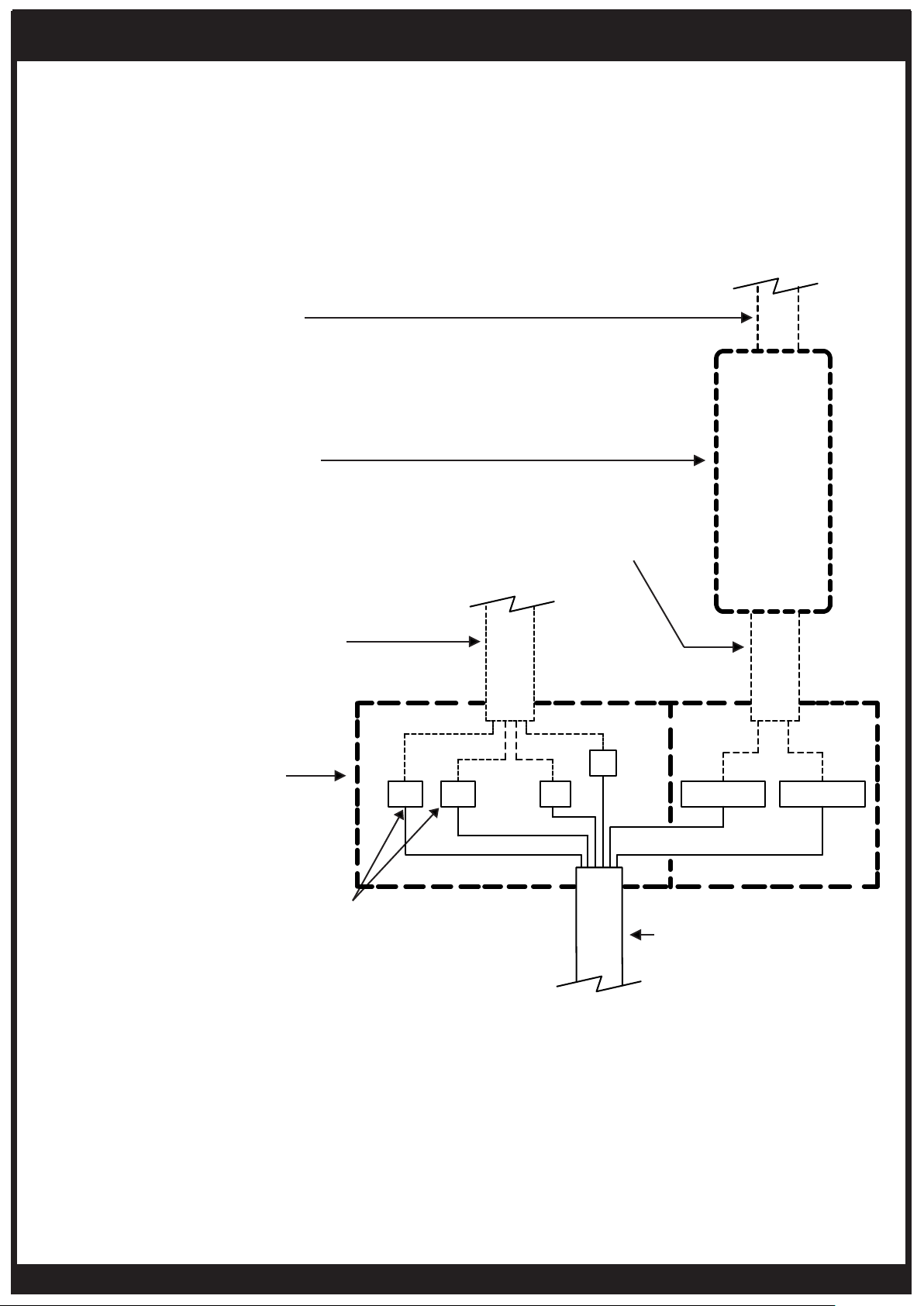
FOR INSTALLATION NOT USING
BROMIC ECLIPSE PENDANT CONTROL
ONLY TO BE INSTALLED & SERVICED BY LICENSED & AUTHORIZED TECHNICIAN.
APPLIANCE MANUAL MUST BE READ BEFORE INSTALLING OR SERVICING THIS PRODUCT.
To control elements independantly L1
(66% element) & L2 (33% element)
need independant 220-240V power
supplies.
Power supply 220-240V - a.c.
Minimum Circuit Ampacity 17A.
(Provided by installer)
Power supply to suit rated
input of transformer
(Provided by installer)
LED Transformer
Output: 24V DC,
Power Rating: 25W Minimum
(Provided by installer)
Junction box & terminals
(Provided by installer)
Transformer wires
(Provided by installer)
Power cable from heater
(Supplied with heater)
WHITE 24V DC
-24V DC
GREEN/
YELLOW
GROUND
LIVE 240V
GREY 240V
NEUTRAL
BLUE
LIVE 240V
BLACK 240V
BROWN 24V DC
+24V DC
+24V DC
G
-24V DCL2 N
L1
TRANSFORMER
OUTPUT 24V DC, 25W MIN
DC OUT 24V
AC IN
PENDANT HEATER CONTROL WIRING DIAGRAM
Loading ...
Loading ...
Loading ...