IMPORTANT INSTRUCTIONS -
OPERATING MANUAL
SAVE THESE INSTRUCTIONS
www.airkinglimited.com
210572021 Rev. U 11-18 1 of 8
Exhaust Fan
BFQ, BFQW Series
READ AND SAVE THESE INSTRUCTIONS
READ CAREFULLY BEFORE ATTEMPTING TO ASSEMBLE, INSTALL, OPERATE OR MAINTAIN
THE PRODUCT DESCRIBED. PROTECT YOURSELF AND OTHERS BY OBSERVING ALL SAFETY
INFORMATION. FAILURE TO COMPLY WITH INSTRUCTIONS COULD RESULT IN PERSONAL
INJURY AND/OR PROPERTY DAMAGE!
RETAIN INSTRUCTIONS FOR FUTURE REFERENCE.
GENERAL SAFETY INFORMATION
When using electrical appliances, basic precautions should
always be followed to reduce the risk of fire, electric shock and
injury to person, including the following:
WARNING:
TO REDUCE THE RISK
OF FIRE, ELECTRIC SHOCK AND INJURY TO
PERSON, OBSERVE THE FOLLOWING:
a) Use this unit only in the manner intended by the manufacturer.If you have
questions, contact the manufacturer.
b) Before servicing or cleaning the unit, switch power off at service
panel and lock the service disconnecting means to prevent power
from being switched on accidentally. When the service disconnecting
means cannot be locked, securely fasten a prominent warning
device, such as a tag, to the service panel.
WARNING: TO REDUCE THE RISK
OF FIRE, ELECTRIC SHOCK AND INJURY TO
PERSON, OBSERVE THE FOLLOWING:
a) Installation work and electrical wiring must be done by qualified
person(s) in accordance with all applicable codes and standards,
including fire-related construction.
b) Sufficient air is needed for proper combustion and exhausting of
gases through the flue (chimney) of fuel burning equipment to prevent
back drafting. Follow the heating equipment manufacturer’s guideline
and safety standards such as those published by the National Fire
Protection Association (NFPA) and the American Society for Heating,
Refrigeration, and Air Conditioning Engineers (ASHRAE), and the local
code authorities.
c) When cutting or drilling into wall or ceiling, do not damage electrical
wiring and other hidden utilities.
CAUTION: FOR GENERAL VENTILATING USE ONLY.
DO NOT USE TO EXHAUST HAZARDOUS OR EXPLOSIVE
MATERIALS AND VAPORS.
d) Ducted fans must always be vented to the outdoors.
e) This unit must be grounded.
f) To avoid motor bearing damage and noisy and/or unbalanced impellers,
keep drywall spray, construction dust, etc. off power unit.
g) Read all instructions before installing or using exhaust fan.
WARNING: TO REDUCE THE RISK OF FIRE,
ELECTRIC SHOCK, DO NOT USE THIS FAN WITH
ANY SOLID-STATE SPEED CONTROL DEVICE.
a) If this unit is to be installed over a tub or shower, it must be
marked as appropriate for the application and be connected to a
GFCI (Ground Fault Circuit Interrupter) – protected branch circuit.
b) Do not install wall mounted fans inside the shower area.
WARNING: DO NOT USE IN KITCHENS.
WARNING: THE DUCTING FROM THIS FAN TO THE
OUTSIDE OF THE BUILDING HAS A STRONG EFFECT
ON THE AIR FLOW, NOISE AND ENERGY USE OF THE FAN. USE
THE SHORTEST, STRAIGHTEST DUCT ROUTING POSSIBLE FOR
BEST PERFORMANCE, AND AVOID INSTALLING THE FAN WITH
SMALLER DUCTS THAN RECOMMENDED. INSULATION AROUND
THE DUCTS CAN REDUCE ENERGY LOSS AND INHIBIT MOLD
GROWTH. FANS INSTALLED WITH EXISTING DUCTS MAY NOT
ACHIEVE THEIR RATED AIRFLOW.
INSTALLATION INSTRUCTIONS
CAUTION: MAKE SURE POWER IS SWITCHED OFF AT
SERVICE PANEL BEFORE STARTING INSTALLATION.
SECTION 1
Preparing the Exhaust Fan
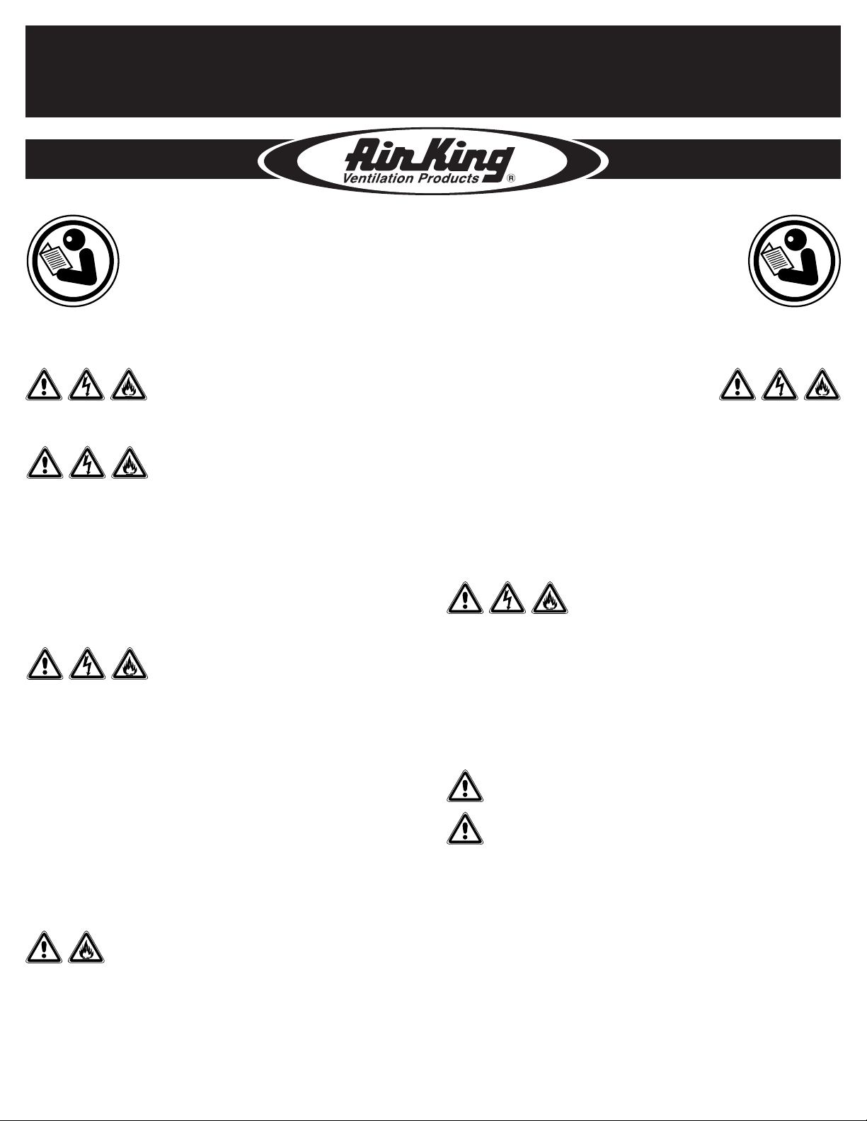
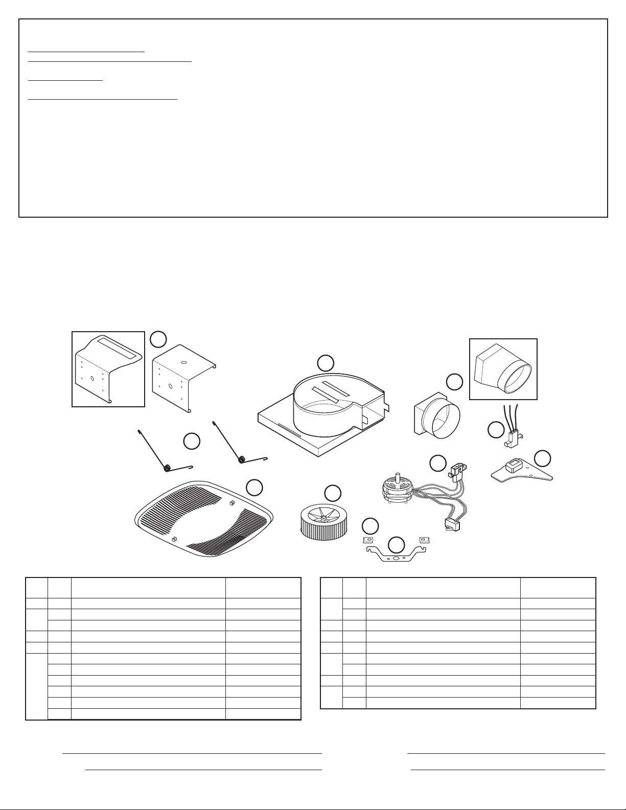
1. Unpack fan from the carton and confirm that all pieces are present. In addition to the
exhaust fan you should have:
1 - Grill 1 - Hardware Bag
1 - Damper Assembly (attached) 1 - Electrical Connector
1 - Mounting Bracket 3 - Wire Nuts
1 - Instruction/Safety Sheet
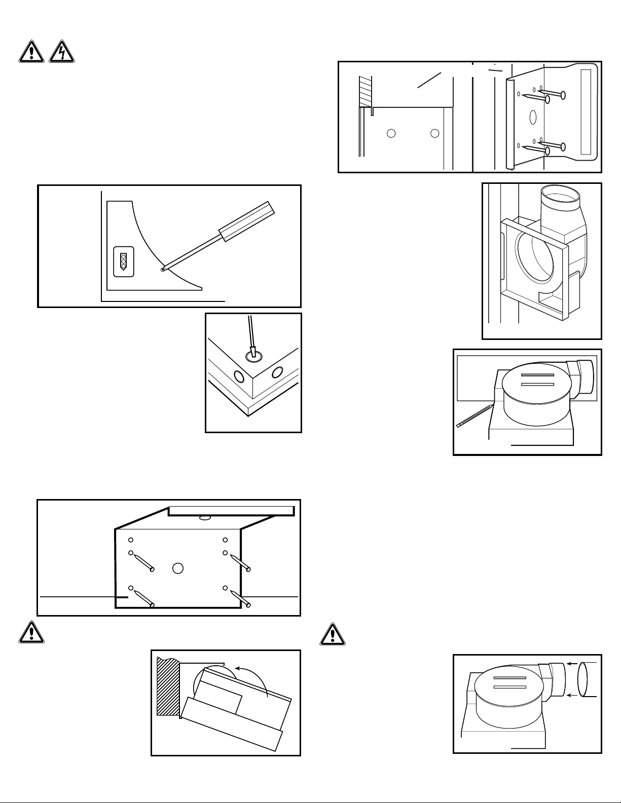
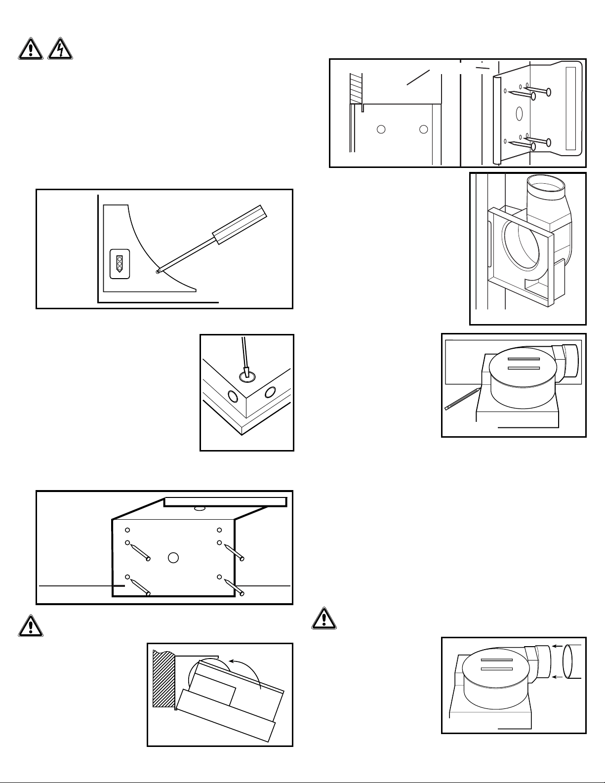
2. Remove the wire compartment cover and store in the carton until needed so it does not
get damaged or lost (Figure 1).
3. Choose the location for your fan. To ensure the best
air and sound performance, it is recommended that
the length of ducting and the number of elbows be
kept to a minimum, the radius of each elbow be as
large as possible for the installation, and that insulated
hard ducting be used. Larger duct sizes will reduce
noise and airflow restrictions.
4. Select the most convenient electrical
knockout and remove using a straight-
blade screw driver (Figure 2).
5. No additional vibration deadening materials are
needed for this fan.
SECTION 2
New Construction - BFQ Models
1. Using the gauge on the mounting bracket, line up the bracket on the joist so the bottom
of the fan will be flush with the finished ceiling. Nail or screw the bracket in place
securely (Figure 3).
WARNING: PROPER INSTALLATION REQUIRES A MINIMUM OF 4
SCREWS LOCATED IN HOLES CLOSEST TO DRYWALL.
2. Snap the fan body into the
bracket (Figure 4). The fan can
be snapped into position with the
duct collar facing to the left or the
right depending which is most
convenient.
www.airkinglimited.com
210572021 Rev. U 11-18 2 of 8
New Construction - BFQW Models (Oval Duct)
1. Using the gauge on the bracket, line up the bracket on the side of a wall stud such that
the bottom of the fan will be flush with the finished wall. The bracket should sit one
drywall thickness forward on the stud (Figure 5).
NOTE: For proper damper operation, the duct
adaptor must be facing up towards the ceiling.
NOTE: ½” minimum thickness drywall must be used for
wall mount applications.
2. Nail or screw the bracket in place securely.
3. Snap the fan body into the bracket, making
sure the duct collar is pointing upwards
towards the ceiling (Figure 6).
SECTION 3
Existing Construction - BFQ Models
1. Position housing against the joist
or stud and trace an outline of
the housing onto the ceiling/wall
material. Set housing aside and cut
opening, being careful not to cut
or damage any electrical or other
hidden utilities (Figure 7).
2. Line up the bracket on the joist so
the bottom of the fan will be flush
with the finished ceiling. Nail or
screw the snap-in bracket in place
securely (Figure 3).
3. Snap the fan body into the bracket (Figure 4). The fan can be snapped into position
with the duct collar facing to the left or the right depending which is most convenient.
Existing Construction - BFQW Models (Oval Duct)
1. Remove a section of the wall material large enough for you to fit the fan housing into as
well as gain access to the top plate, and have enough space to connect the ducting. This
will typically be across two studs and approximately 24" starting at the top of the wall.
2. Follow the instructions in Section 2 - New Constructions - BFQW Models (Oval Duct) to
complete the installation.
NOTE: Wall installation into existing construction will require you to patch the wall material
around the unit.
SECTION 4
Ducting
NOTE: 4" OR LARGER RIGID DUCT IS RECOMMENDED FOR BEST PERFORMANCE.
CAUTION: ALL DUCTING MUST COMPLY WITH LOCAL AND NATIONAL
BUILDING CODES.
1. Connect the ducting to the fan’s duct
collar (Figure 8). Secure in place
using tape or screw clamp. Always
duct the fan to the outside through a
wall or roof cap. It is recommended
that low restriction termination
fittings be used.
NOTE: For oval duct connection, squeeze
standard 4" round rigid ducting to form
an oval shape then follow instructions in
Step 1.
Figure 2
Figure 4
Figure 1
Figure 6
Figure 3
Figure 5
Drywall
Wall Stud
Figure 7
Round duct
collar shown
Figure 8
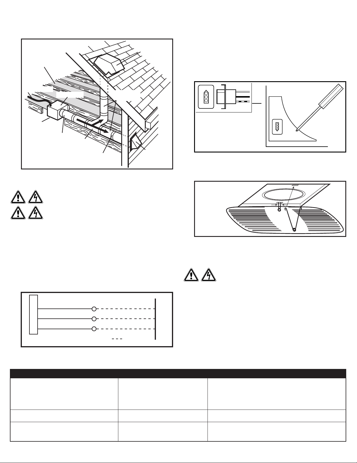
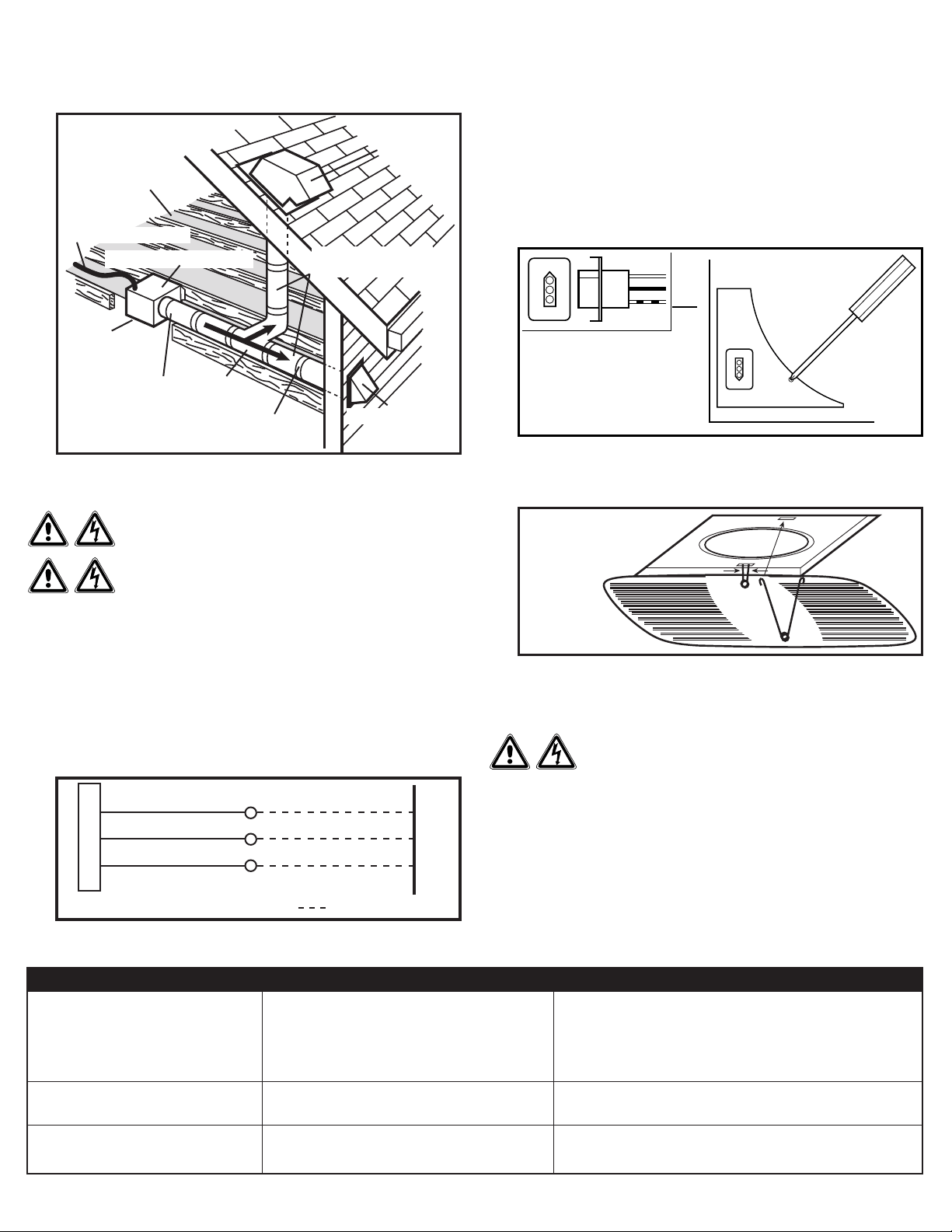
2. Ensure duct joints and exterior penetrations are sealed with caulk or other similar
material to create an air-tight path to minimize building heat loss or gain and to reduce
the potential for condensation. Place/wrap insulation around duct and/or fan to in order
to minimize possible condensation buildup within the duct, as well as building heat loss
or gain (Figure 9).
SECTION 5
Wiring
CAUTION: MAKE SURE POWER IS SWITCHED OFF AT
SERVICE PANEL BEFORE STARTING INSTALLATION.
CAUTION: ALL ELECTRICAL CONNECTIONS MUST BE
MADE IN ACCORDANCE WITH LOCAL CODES, ORDINANCES, OR
NATIONAL ELECTRICAL CODE. IF YOU ARE UNFAMILIAR WITH METHODS OF INSTALLING
ELECTRICAL WIRING, SECURE THE SERVICES OF A QUALIFIED ELECTRICIAN.
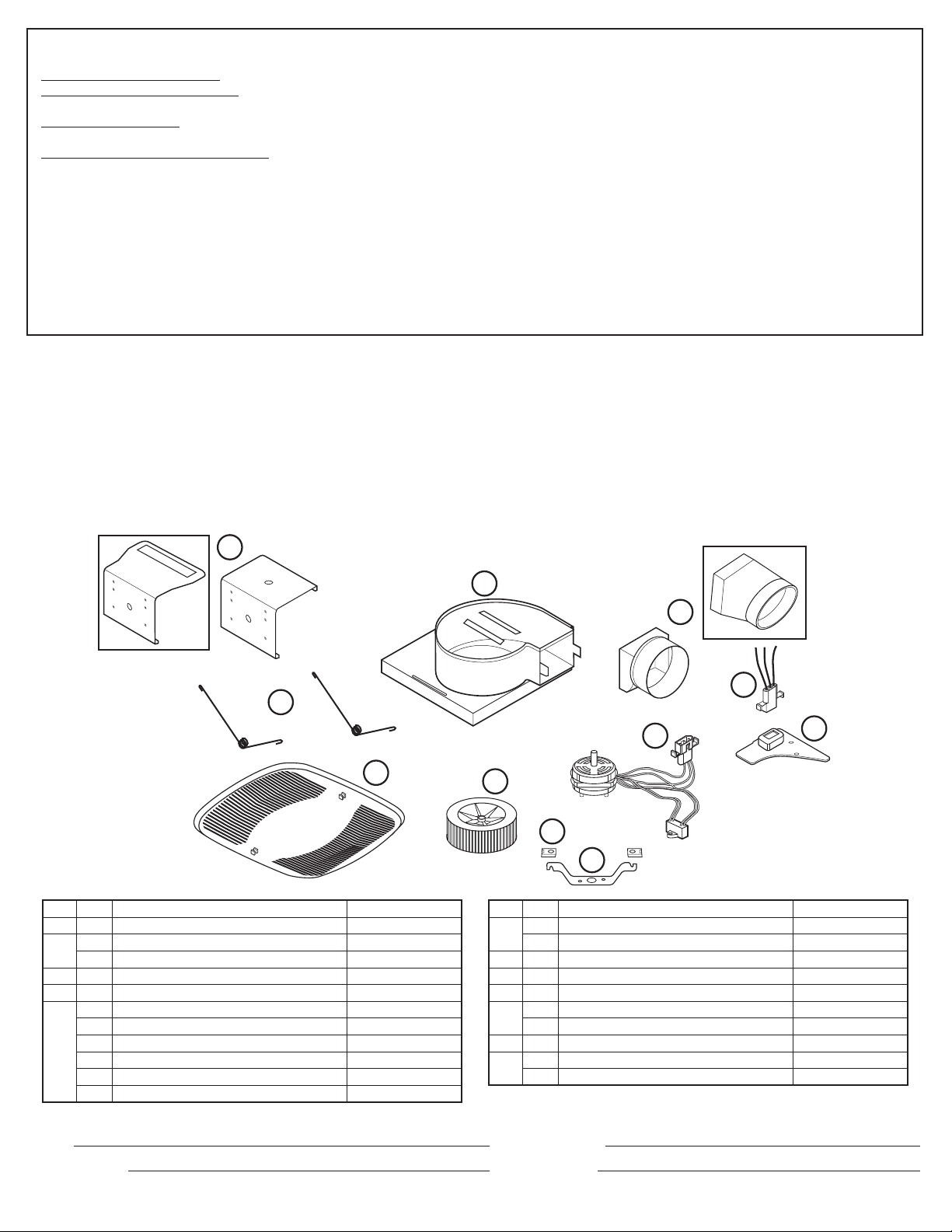
1. Run wiring from an approved wall switch carrying the appropriate rating. One neutral
(white), one ground (green or bare copper), and one hot (black lead connected to
the switch). Secure the electrical wires to the housing with an approved electrical
connector. Make sure you leave enough wiring in the box to make the connection to the
fan’s receptacle.
2. From where you have access to inside the fan’s junction box, connect the White wire
from the house to the White wire from the fan’s receptacle. Connect the Black wire from
the wall switch to the Black wire from the fan’s receptacle. Connect the ground wire
from the house to the Green wire from the fan’s receptacle (Figure 10). Use approved
methods for all connections.
www.airkinglimited.com
210572021 Rev. U 11-18 3 of 8
SECTION 6
Completing the Installation
1. Use a sealant appropriate for contact with the building materials present and for the
temperature requirements of the installation to prevent air leakage from unconditioned
spaces is recommended. If gaps between unit housing and ceiling are great, additional
material (backing rod, ceiling material) may be required.
NOTE: This fan is rated for direct insulation contact (Type IC) and it is recommended that this fan
be completely covered by insulation in order to reduce heat loss or gain to unconditioned space.
2. Reinstall the fan’s wire compartment cover. Rotate the blower wheel by hand to
ensure it spins freely. Plug the fan’s quick connect motor cord into the receptacle.
This cord will only fit one way into the receptacle (Figure 11).
NOTE: If using this fan to meet ASHRAE 62.2 requirements, locate the label inside the fan
housing and fill in the appropriate information.
3. Install the grill by squeezing the two ends of the springs together and installing them up
into the slots of the fan’s housing. Push the grill up into position (Figure 12).
4. Restore power and test your installation.
SECTION 7
Use and Care
CAUTION: MAKE SURE POWER IS SWITCHED OFF AT
SERVICE PANEL BEFORE SERVICING THE UNIT.
1. Cleaning the Grill: Remove grill and use a mild detergent, such as dishwashing liquid,
and dry with a soft cloth. NEVER USE ANY ABRASIVE PADS OR SCOURING POWDERS.
Completely dry grill before reinstalling. Refer to instructions in Section 6 Finishing the
Installation, to reinstall grill.
2. Cleaning the Fan Assembly: Unplug the motor cord from receptacle. Wipe all parts
with a dry cloth or gently vacuum the fan. NEVER IMMERSE ELECTRICAL PARTS IN
WATER. Plug the motor cord back in and restore power.
Figure 9
Insulation*
(place around and
over Fan Housing
Fan Housing
Power Cable*
Seal gaps
around Housing
Round
Duct*
Seal duct joints
with tape
Round
Elbows*
Wall Cap*
Roof Cap*
(with built-in
damper)
Keep duct
runs short
*Purchase separately
or
Figure 10
Supply from house
Black
Neutral (White)
Ground (Green or Bare)
Fan
Neutral (White)
Green
Black
By others
Figure 11
Figure 12
Troubleshooting Guide
Trouble Probable Cause Suggested Remedy
1. Fan does not operate when the switch is on. 1a. A fuse may be blown or a circuit tripped. 1a. Replace fuse or reset circuit breaker.
1b. Connector plug from motor is not plugged in. 1b. Turn off power to unit. Remove Grill and plug motor into receptacle
in housing. Restore power to unit.
1c. Wiring is not connected properly. 1c. Turn off power to unit. Check that all wires are connected.
1d Motor has stopped operating. 1d. Replace motor.
2. Fan is operating, but air moves slower than normal. 2. Obstruction in the exhaust ducting. 2. Check for any obstructions in the ducting. The most common are bird
nests in the roof cap or wall cap where the fan exhausts to the outside.
3. Fan is operating louder than normal 3a. Motor is loose. 3a. Turn off power to unit. Remove grill and check that all screws are fully
tightened. Restore power to unit.
3b. Fan blade is hitting housing of unit. 3b. Call your dealer for service.
www.airkinglimited.com
210572021 Rev. U 11-18 4 of 8
Installer: Installation Date:
Place of Purchase: Model Number:
LIMITED WARRANTY
WHAT THIS WARRANTY COVERS: This product is warranted against defects in workmanship and/or materials.
HOW LONG THIS WARRANTY LASTS: This warranty extends only to the original purchaser of the product and lasts for five (5) years from the date of original purchase
or until the original purchaser of the product sells or transfers the product, whichever first occurs.
WHAT AIR KING WILL DO: During the warranty period, Air King will, at its sole option, repair or replace any part or parts that prove to be defective or replace the whole
product with the same or comparable model.
WHAT THIS WARRANTY DOES NOT COVER: This warranty does not apply if the product was damaged or failed because of accident, improper handling or operation,
shipping damage, abuse, misuse, unauthorized repairs made or attempted. This warranty does not cover shipping costs for the return of products to Air King for repair or
replacement. Air King will pay return shipping charges from Air King following warranty repairs or replacement
ANY AND ALL WARRANTIES, EXPRESSED OR IMPLIED (INCLUDING, WITHOUT LIMITATION, ANY IMPLIED WARRANTY OF MERCHANTABILITY), LAST FIVE YEARS
FROM THE DATE OF ORIGINAL PURCHASE OR UNTIL THE ORIGINAL PURCHASER OF THE PRODUCT SELLS OR TRANSFERS THE PRODUCT, WHICHEVER FIRST
OCCURS AND IN NO EVENT SHALL AIR KING’S LIABILITY UNDER ANY EXPRESS OR IMPLIED WARRANTY INCLUDE (I) INCIDENTAL OR CONSEQUENTIAL DAMAGES
FROM ANY CAUSE WHATSOEVER, OR (II) REPLACMENT OR REPAIR OF ANY HOUSE FUSES, CIRCUIT BREAKERS OR RECEPTACLES. NOTWITHSTANDING ANYTHING TO
THE CONTRARY, IN NO EVENT SHALL AIR KING’S LIABILITY UNDER ANY EXPRESS OR IMPLIED WARRANTY EXCEED THE PURCHASE PRICE OF THE PRODUCT
AND ANY SUCH LIABILITY SHALL TERMINATE UPON THE EXPIRATION OF THE WARRANTY PERIOD.
Some states and provinces do not allow limitations on how long an implied warranty lasts, or the exclusion or limitation of incidental or consequential damages, so these
exclusions or limitations may not apply to you. This warranty gives you specific legal rights. You may also have other rights which vary from state to state and province to
province. Proof of purchase is required before a warranty claim will be accepted.
CUSTOMER SERVICE:
Toll-Free (800) 465-7300
Our Customer Service team is available to assist you with product questions, service center locations, and replacement parts. They can be reached Monday through
Friday, 8am-4pm Eastern. Please have your model number available, as well as the type and style (located on the label inside of your product).
Please do not return product to place of purchase.
www.airkinglimited.com
PARTS FOR DISCONTINUED, OBSOLETE AND CERTAIN OTHER PRODUCTS MAY NOT BE AVAILABLE. DUE TO SAFETY REASONS, MANY ELECTRONIC COMPONENTS
AND MOST HEATER COMPONENTS ARE NOT AVAILABLE TO CONSUMERS FOR INSTALLATION OR REPLACEMENT.
# Qty. Description Replacement Part #
1 1 Fan Housing 5S2205001
2 1 Damper Assembly - BFQ 5S2299054
1 Damper Assembly - BFQW 5S2299055
3 1 Receptacle 3P 5S2205004
4 1 Wire Cover 5S2205005
5 1 Motor - BFQ50, BFQ50W 5S2205035
1 Motor - BFQ60 5S2205036
1 Motor - BFQ70,BFQ70W 5S2205037
1 Motor - BFQ75 5S2205037
1 Motor - BFQ80 5S2205034
1 Motor - BFQ90 5S2299001
# Qty. Description Replacement Part #
5 1 Motor - BFQ110 5S2205008
1 Motor - BFQ140 5S2299002
6 2 Clip 5S2205009
7 1 Motor Bracket 5S2299003
8 1 Blower Wheel 5S2299004
9 1 Grill - BFQ 5S2205011
1 Grill - BFQW 5S2299056
10 2 Grill Springs 5S2205012
11 1 Snap In Bracket - BFQ 5S2205013
1 Snap In Bracket - BFQW 5S2202057
1
2
3
4
5
6
7
8
9
10
11
INSTRUCTIONS IMPORTANTES –
MODE D’EMPLOI
CONSERVER CES INSTRUCTIONS
www.airkinglimited.com
210572021 Rev. U 11-18 5 of 8
Ventilateur d’Évacuation
Série BFQ et BFQW
LIRE ET CONSERVER CES INSTRUCTIONS
LIRE SOIGNEUSEMENT AVANT DE TENTER D’ASSEMBLER, INSTALLER, OPÉRER OU DE
RÉPARER LE PRODUIT DÉCRIT. PROTÉGEZ VOUS-MÊME ET LES AUTRES EN OBSERVANT
TOUTE L’INFORMATION DE SÉCURITÉ. FAILLIR À SE CONFORMER AUX INSTRUCTIONS PEUT
RÉSULTER EN BLESSURE PERSONNELLE GRAVE ET/OU EN DOMMAGE À LA PROPRIÉTÉ.
CONSERVER CES INSTRUCTIONS POUR RÉFÉRENCES FUTURES.
INSTRUCTIONS GÉNÉRALES DE SÉCURITÉ
Lors de l’utilisation d’appareils électriques, des précautions
de base doivent toujours être suivies pour réduire les risques
d’incendie, de choc électrique et de blessures corporelles, incluant ce qui suit:
AVERTISSEMENT :
POUR RÉDUIRE
LES RISQUES D’INCENDIE, DE CHOC ÉLECTRIQUE
OU DE BLESSURES PERSONNELLES OBSERVER CE QUI SUIT:
a) Utiliser cette unité seulement de la manière pour laquelle le fabricant l’a
conçu. Si vous aviez des questions, veuillez contacter le fabricant.
b) Avant d’effectuer un service ou de nettoyer l’unité, couper
l’alimentation électrique dans le panneau de distribution et verrouiller
le dispositif de déconnexion afin d’éviter que l’alimentation ne
revienne accidentellement. Lorsque le dispositif ne peut être
verrouillé, fixer solidement un avis d’avertissement, tel qu’une
étiquette, au panneau de distribution.
AVERTISSEMENT : POUR RÉDUIRE
LES RISQUES D’INCENDIE, DE CHOC ÉLECTRIQUE
OU DE BLESSURES PERSONNELLES OBSERVER CE QUI SUIT:
a) Le travail d’installation et le câblage électrique doivent être effectués par
une(des) personne(s) qualifiée(s) en conformité avec tous les codes et
normes applicables, incluant la construction relative aux incendies.
b) De l’air en quantité suffisante est requis pour la bonne combustion
et l’évacuation de gaz par le conduit (cheminée) provenant d’équipement
de brûlage au combustible pour prévenir un
refoulement. Suivre les directives du fabricant de l’équipement de
chauffage et les normes de sécurité telles que celles publiées par la
National Fire Protection Association (NFPA) et de la American Society for
Heating, Refrigeration, and Air Conditioning Engineers (ASHRAE), et de
celles des autorités locales du code.
c) Lors de coupe ou de perçage des murs et plafonds, ne pas
endommager le filage électrique et autres utilités cachées.
ATTENTION : POUR USAGE DE VENTILATION
GÉNÉRALE EXCLUSIVEMENT. NE PAS UTILISER POUR
ÉVACUER DU MATÉRIEL ET DES VAPEURS DANGEREUSES OU EXPLOSIVES.
d) Les ventilateurs avec conduits doivent toujours être évacués vers
l’extérieur
e) Cette unité doit être mise à la terre
f) Pour éviter des dommages aux roulements des moteurs et/ou des
hélices bruyantes ou déséquilibrées, empêcher la poussière de cloison
sèche, poussière de construction, etc., d’atteindre l’unité de puissance.
g) Lire toutes les instructions avant d’installer ou d’utiliser la ventilateur.
AVERTISSEMENT : POUR RÉDUIRE
LES RISQUES D’INCENDIE OU DE CHOC
ÉLECTRIQUE, NE PAS UTILISER CE VENTILATEUR AVEC UN RÉGULATEUR
DE VITESSE ÉLECTRONIQUE.
a) Si cet appareil doit être installé au-dessus d’une baignoire
ou d’une douche, il doit être marqué comme approprié pour
l’application et connecté à un DDFT (disjoncteur différentiel de
fuite à la terre) - circuit de dérivation protégé.
b) N’installez pas les ventilateurs muraux à l’intérieur de la zone de
douche.
AVERTISSEMENT : NE PAS UTILISER DANS LES
CUISINES
AVERTISSEMENT : LA CANALISATION DE CE
VENTILATEUR À L’EXTÉRIEUR DU BÂTIMENT A UN EFFET
IMPORTANT SUR LE FLUX D’AIR, LE BRUIT ET LA CONSOMMATION
D’ÉNERGIE DU VENTILATEUR. UTILISEZ LA ROUTE DE CANALISATION
LA PLUS COURTE ET LA PLUS DROITE POSSIBLE POUR UNE MEILLEURE
PERFORMANCE, ET ÉVITEZ D’INSTALLER LE VENTILATEUR AVEC
DES CONDUITS PLUS PETITS QUE RECOMMANDÉ. L’ISOLATION
AUTOUR DES CONDUITS PEUT RÉDUIRE LA PERTE D’ÉNERGIE ET
EMPÊCHER LE DÉVELOPPEMENT DE MOISISSURES. IL SE PEUT QUE
LES VENTILATEURS INSTALLÉS AVEC DES CONDUITS EXISTANTS
N’ATTEIGNENT PAS LEUR DÉBIT D’AIR NOMINAL.
INSTRUCTIONS D’INSTALLATION
ATTENTION :
VOUS ASSURER QUE L’ALIMENTATION
EST COUPÉE AU PANNEAU DE SERVICE AVANT DE COMMENCER
L’INSTALLATION.
SECTION 1
Préparation du Ventilateur d’évacuation
1. Sortir le ventilateur de sa boite et confirmer que toutes les pièces sont présentes. En
plus du ventilateur d’évacuation vous devriez avoir :
1 - Grille 1 - Sac de la Quincaillerie
1 - Ensemble de clapet (attaché) 1 - Connecteur Électrique
1 - Support de Montage 3 - Coinceurs à Câbles
1 - Sac de la Quincaillerie
1 - Feuillet d’instructions / sécurité
2. Enlever le couvercle du compartiment à câble et le ranger dans l’emballage jusqu’à ce
que vous en ayez besoin afin qu’il ne soit pas perdu ou endommagé (Figure 1).
3. Choisir l’emplacement pour votre ventilateur. Pour garantir la meilleure qualité d’air et
performance acoustique, il est recommandé que la longueur de la canalisation et le
nombre de coudes soient réduits au minimum, que le
rayon de chaque coude soit aussi grand que possible
pour l’installation, et que des conduits rigides isolés
soient utilisés. Des conduits plus gros réduiront le bruit
et les restrictions du débit d’air.
4. Sélectionner l’alvéole défonçable la mieux appropriée
et l’enlever à l’aide d’un tournevis à lame plate
(Figure 2).
5. Aucun matériel amortissant de vibrations
supplémentaire n’est nécessaire pour ce ventilateur.
SECTION 2
Nouvelle construction - Modèles BFQ
1. En utilisant le guide sur le support de montage, aligner le support sur la solive pour
que le dessous du ventilateur soit à effleurement avec le plafond fini. Clouer ou visser
solidement le support en place (Figure 3).
ATTENTION : POUR UNE INSTALLATION APPROPRIÉE, UTILISEZ
UN MINIMUM DE 4 VIS SITUÉES DANS LES TROUS LES PLUS PROCHES DES
PLAQUES DE PLÂTRE.
2. Fixer par pression le bâti du
ventilateur dans le support (Figure
4). Le ventilateur peut être fixé par
pression en position avec le collet de
conduit faisant face à gauche ou à
droite en fonction de quelle direction
est la plus pratique.
www.airkinglimited.com
210572021 Rev. U 11-18 6 of 8
Nouvelle construction - Modèles BFQW (Conduit ovale)
1. Utilisant le gabarit du support, alignez le support sur le côté d’un poteau de cloison de
telle sorte que le fond du ventilateur soit au même niveau que le mur fini. Le support
doit reposer sur une épaisseur de plaque de plâtre en avant sur le goujon (Figure 5).
NOTE : Pour un fonctionnement correct de
l’amortisseur, l’adaptateur du conduit doit être
orienté vers le haut vers le plafond.
NOTE : Vous devez utiliser des cloisons de plâtre
d’épaisseur minimale de ½ po pour les applications
de montage mural.
2. Clouez ou vissez solidement le support.
3. Verrouillez le corps du ventilateur dans le
support, en vous assurant que le collet du
conduit est dirigé vers le haut vers le plafond
(Figure 6).
SECTION 3
Construction Existante - Modèles BFQ
1. Positionner le cabinet contre la solive ou le
montant et tracer le contour du cabinet sur le
matériau du mur / plafond. Mettre
le cabinet de côté et découper
l’ouverture, en prenant bien soin
de ne pas couper ou endommager
d’utilité électrique ou dissimulée
(Figure 7).
2. Aligner le support sur la solive de
manière que le bas du ventilateur
soit à effleurement avec le plafond
fini. Clouer ou visser solidement le
support à fixer par pression en place
(Figure 3).
3. Fixer par pression le bâti du ventilateur dans le support (Figure 4). Le ventilateur peut
être fixé par pression en position avec le collet de conduit faisant face à gauche ou à
droite en fonction de quelle direction est la plus pratique.
Construction Existante - Modèles BFQW (Conduit ovale)
1. Retirez une partie du matériau du mur, assez grande pour faire place au boîtier du
ventilateur, donner accès à la plaque supérieure, et avoir suffisamment d’espace pour
connecter le conduit. Ce sera typiquement entre deux poteaux et environ 24 po à partir
du haut du mur.
2. Suivez les instructions de la Section 2 - Nouvelles constructions - modèles BFQW
(Conduit ovale) pour terminer l’installation.
NOTE : L’installation dans un mur déjà construit vous obligera à repérer le mur autour de l’appareil.
SECTION 4
Conduits
NOTE: UN CONDUIT PLUS RIGIDE DE 4 PO OU PLUS EST RECOMMANDE POUR UNE
MEILLEURE PERFORMANCE.
ATTENTION : TOUS LES CONDUITS DOIVENT ÊTRE CONFORMES
AUX CODES DU BÂTIMENT LOCAUX ET NATIONAUX.
1. Raccorder le conduit au collet de
conduit du ventilateur (Figure 8). Fixer
en place à l’aide de ruban ou de serre-
joint. Toujours évacuer le ventilateur
vers l’extérieur au travers de chapeau
mural ou de toit. Il est recommandé
que les raccords d’extrémité basse de
restriction sont utilisées.
NOTE : Pour le raccordement du conduit
ovale, presser un conduit standard rigide
circulaire de 4 po pour former une forme
ovale puis suivez les instructions à l’étape 1.
Figure 2
Figure 5
Cloison sèche
Poteaux
Figure 4
Figure 1
Figure 6
Figure 3
Figure 7
Collet de conduit
circulaire illustré
Figure 8
2. Assurez-vous que les joints des conduits et les pénétrations extérieures sont scellés
avec du mastic ou tout autre matériau similaire pour créer un passage d’air étanche
afin de minimiser la perte ou le gain de chaleur et réduire le risque de condensation.
Placez / enveloppez l’isolant autour du conduit et / ou ventilateur afin de minimiser la
possibilité d’accumulation de condensation à l’intérieur du conduit, ainsi que la perte ou
le gain de chaleur (Figure 9).
SECTION 5
Câblage
ATTENTION : VOUS ASSURER QUE L’ALIMENTATION
EST COUPÉE AU PANNEAU DE SERVICE AVANT DE COMMENCER
L’INSTALLATION.
ATTENTION : TOUTES LES CONNEXIONS DOIVENT ÊTRE
FAITES EN CONFORMITÉ AVEC LES CODES ÉLECTRIQUES LOCAUX OU
NATIONAUX. SI VOUS N’ÊTES PAS FAMILIER AVEC LES MÉTHODES D’INSTALLATION DE
CÂBLAGE ÉLECTRIQUE, RECOURREZ AUX SERVICES D’UN ÉLECTRICIEN QUALIFIÉ.
1. Courir le filage d’un interrupteur mural approuvé de calibre approprié. Un fil neutre
(blanc), un fil de mise à la terre (vert ou cuivre dénudé), et un fil vivant (fil noir connecté
à l’interrupteur). Fixer les fils électriques au cabinet à l’aide d’un connecteur électrique
approuvé. Assurez-vous de laisser suffisamment de fil dans la boite de raccord pour la
connexion au réceptacle du ventilateur.
2. De là où vous avez accès à l’intérieur de la boite de jonction du ventilateur, connecter le fil
Blanc provenant de la résidence au fil Blanc du réceptacle du ventilateur. Connecter le fil Noir
de l’interrupteur mural au fil Noir du réceptacle du ventilateur. Connecter le fil de mise à la
terre provenant de la résidence au fil Vert du réceptacle du ventilateur (Figure 10). Utiliser
des méthodes approuvées pour toutes les connexions.
www.airkinglimited.com
210572021 Rev. U 11-18 7 of 8
SECTION 6
Complétion de l’installation
1. Il est recommandé d’utiliser un scellant approprié pour le contact avec les matériaux
de construction actuels et pour les besoins de la température de l’installation, afin
d’empêcher les fuites d’air à partir des espaces non conditionnés. S’il y a des grands
écarts entre le boîtier de l’appareil et le plafond, du matériel supplémentaire (tige de
support, matériel de plafond) peut être nécessaire.
NOTE : Ce ventilateur est conçu pour le contact d’isolation directe (type IC). Il est aussi
recommandé que ce ventilateur soit complètement recouvert par l’isolation afin de réduire la
perte de chaleur ou de gagner de l’espace inconditionné.
2. Réinstaller le couvercle du compartiment de câble du ventilateur en place. Faire tourner
la roue de la soufflante à la main pour vous assurer qu’elle tourne librement. Brancher
le cordon à raccordement rapide dans le réceptacle. Ce cordon ne s’ajuste que d’une
seule façon dans le réceptacle (Figure 11).
NOTE: Si vous utilisez ce ventilateur pour répondre aux exigences de la norme ASHRAE 62.2, repérez
l’étiquette à l’intérieur du boîtier du ventilateur et complétez les informations appropriées.
3. Installer la grille en pressant ensemble les deux extrémités des ressorts et en les installant
dans les fentes du châssis du ventilateur. Pousser la grille en position (Figure 12).
4. Restaurer l’alimentation et tester votre installation.
SECTION 7
Use and Care
ATTENTION : VOUS ASSURER QUE L’ALIMENTATION
EST COUPÉE AU PANNEAU DE SERVICE AVANT DE COMMENCER
L’INSTALLATION.
1. Nettoyage de la grille : Retirer la grille et utiliser un détergent doux, tel que du liquide
pour la vaisselle, puis sécher à l’aide d’un chiffon doux. NE JAMAIS UTILISER D’ABRASIF
OU DE POUDRE À RÉCURER. Sécher complètement la grille avant de la réinstaller. Pour
réinstaller la grille, vous référer à la Section 6 - Complétion de l’installation.
2. Nettoyage de l’assemblage du ventilateur : Débrancher le cordon du moteur de
son réceptacle. Nettoyer toutes les pièces avec un chiffon sec ou passer délicatement
l’aspirateur dans le ventilateur. NE JAMAIS IMMERGER DES PIÈCES ÉLECTRIQUES DANS
L’EAU. Rebrancher le cordon et remettre l’alimentation.
Figure 9
Isolant*
(placer autour et au-
dessus du logement
du ventilateur)
Logement du ventilateur
Câble d’alimentation*
Sceller les
espaces autour
du logement
Conduit
rond*
Sceller les joints
avec du ruban
Coudes
ronds*
Capuchon de mur*
Capuchon de toit*
(avec amortisseur
intégré)
Garder les
canalisations courtes
*Acheter séparément
ou
Figure 10
Alimentation provenant
de la résidence
Noir
Neutre (Blanc)
Mise à la terre (vert ou nu)
Ventilateur
Neutre (Blanc)
Vert
Noir
Par d’autres
Figure 11
Figure 12
Guide de dépannage
Trouble Cause Possible Solution Suggérée
1. Le ventilateur ne fonctionne pas lorsque 1a. Un fusible peut être grillé ou un disjoncteur 1a. Remplacer le fusible ou réinitialiser le disjoncteur.
l’interrupteur est à la position en marche. peut être décle.nché.
1b. La fiche de raccord du moteur n’est 1b. Couper l’alimentation à l’unité. Retirer la grille et brancher le moteur dans
pas connectée. le réceptacle dans le cabinet. Remettre l’alimentation sur l’unité.
1c. Le câblage n’est pas raccordé correctement. 1c. Couper l’alimentation de l’unité. Vérifier que tous les fils sont raccordés.
1d. La moteur est terminee 1d. Remplacez la moteur
2. Le ventilateur fonctionne, mais l’air circule 2. Obstruction dans les conduits d’évacuation. 2. Vérifier pour toute obstruction dans les conduits. Les plus courantes sont
plus lentement que la normale. des nids d’oiseau dans le chapeau de toit ou mural là où le ventilateur
s’évacue vers l’extérieur.
3. Le ventilateur fonctionne de manière plus 3a. Le moteur est lâche. 3a. Couper l’alimentation à l’unité. Retirer la grille et vérifier que toutes les
bruyante que la normale. vis sont complètement serrées. Remettre l’alimentation sur l’unité.
3b. L’hélice du ventilateur frotte contre le cabinet de l’unité. 3b. Appeler votre marchand pour un service.
www.airkinglimited.com
210572021 Rev. U 11-18 8 of 8
Installateur : Date d’installation :
Endroit de l’achat : Numéro de modèle :
GARANTIE LIMITÉE
QUE COUVRE CETTE GARANTIE : Ce produit est garanti contre tout vice de fabrication ou de matière.
COMBIEN DE TEMPS CETTE GARANTIE DURE : Cette garantie se rapporte seulement à l’acheteur original du produit et dure pendant cinq (5) années de la date de
l’achat original ou jusqu’à ce que l’acheteur original du produit vend ou transfère le produit, celui qui se produit en premier.
QUE FERA AIR KING : Au cours de la période de garantie, Air King, à son choix, réparera ou remplacera n’importe quelle partie ou pièces qui s’avèrent défectueuses ou
remplacera le produit entier par le même modèle ou un modèle comparable.
CE QUE CETTE GARANTIE NE COUVRE PAS : Cette garantie ne s’applique pas si le produit était endommagé ou arrête de fonctionner en raison d’un accident, d’une
mauvaise manipulation ou opération, de dommages d’expédition, d’abus, de mauvaise utilisation, de réparation faite ou tentées non autorisées. Cette garantie ne couvre
pas les coûts d’expédition pour le retour des produits à Air King pour la réparation ou le remplacement. Air King payera les frais d’expédition de retour de Air King après les
réparations ou le remplacement de garantie.
TOUTES LES GARANTIES, EXPRESSES OU TACITES (COMPRENANT, SANS LIMITATION, TOUTE GARANTIE TACITE DE VALEUR MARCHANDE), DURENT CINQ ANNÉES
DE LA DATE DE L’ACHAT ORIGINAL OU JUSQU’À CE QUE L’ACHETEUR ORIGINAL DU PRODUIT VEND OU TRANSFÈRE LE PRODUIT, CELUI QUI SE PRODUIT EN PREMIER
ET DANS AUCUN CAS AIR KING N’ASSUME AUCUNE RESPONSABILITÉ EXPRESSE OU TACITE POUR (I) DES DOMMAGES ACCIDENTELS OU INDIRECTS DE N’IMPORTE
QUELLE CAUSE, OU (II) LE REPLACEMENT OU LA RÉPARATION DE TOUS FUSIBLES, DISJONCTEURS OU RÉCEPTACLES DE MAISON. MALGRÉ N’IMPORTE QUOI À
L’EFFET CONTRAIRE, DANS AUCUN CAS LA RESPONSABILITÉ D’AIR KING, SOUS UNE GARANTIE EXPRESSE OU TACITE, NE DÉPASSERA LE PRIX D’ACHAT DU PRODUIT
ET UNE TELLE RESPONSABILITÉ SE TERMINERA AVEC L’EXPIRATION DE LA PÉRIODE DE GARANTIE.
Certains états et provinces ne permettent pas les limitations de la période de garantie, ou l’exclusion ou la restriction des dommages accidentels ou indirects, et, par
conséquent, les présentes restrictions ne peuvent pas s’appliquer. La présente garantie vous donne des droits légaux spécifiques et peut-être certains autres droits qui
peuvent varier selon la province. La preuve d’achat est exigée avant qu’une réclamation de garantie ne soit acceptée.
SERVICE À LA CLIENTÈLE :
Sans frais (800) 465-7300
Notre équipe de service à la clientèle est disponible pour vous aider avec des questions sur le produit, les adresses des centres de service, et les pièces de rechange.
Vous pouvez la rejoindre, du lundi au vendredi, de 8h:00 à 16h:00 HNE. Veuillez avoir le numéro du modèle disponible, ainsi que le genre et le style (qui se trouvent sur
l’étiquette à l’intérieur de votre produit). Veuillez ne pas renvoyer le produit à l’endroit de l’achat.
www.airkinglimited.com
IL SE PEUT QUE LES PIÈCES POUR LES PRODUITS DISCONTINUÉS, OBSOLÈTES ET AUTRES PRODUITS NE SOIENT PAS DISPONIBLES. POUR DES RAISONS
DE SÛRETÉ, BEAUCOUP DE COMPOSANTS ÉLECTRONIQUES ET LA PLUPART DES COMPOSANTS DES CHAUFFAGES NE SONT PAS À LA DISPOSITION DES
CONSOMMATEURS POUR L’INSTALLATION OU LE REMPLACEMENT.
1
2
3
4
5
6
7
8
9
10
11
# de pièce
# Qté. Description de remplacement
1 1 Cabinet du ventilateur 5S2205001
2 1 Assemble du Clapet - BFQ 5S2299054
1 Assemble du Clapet - BFQW 5S2299055
3 1 Réceptacle 3P 5S2205004
4 1 Couvercle des câbles 5S2205005
5 1 Moteur - BFQ50, BFQ50W 5S2205035
1 Moteur - BFQ60 5S2205036
1 Moteur - BFQ70, BFW70W 5S2205037
1 Moteur - BFQ75 5S2205037
1 Moteur - BFQ80 5S2205034
1 Moteur - BFQ90 5S2299001
# de pièce
# Qté. Description de remplacement
5 1 Moteur - BFQ110 5S2205008
1 Moteur - BFQ140 5S2299002
6 2 Clip 5S2205009
7 1 Support du Moteur 5S2299003
8 1 Roue de la Soufflante 5S2299004
9 1 Grille - BFQ 5S2205011
1 Grille - BFQW 5S2299056
10 2 Ressorts de la grille 5S2205012
11 1 Support à Fixer par Pression - BFQ 5S2205013
1 Support à Fixer par Pression - BFQW 5S2202057