1
English
OPERATION MANUAL
MODELS
Air Handling Unit
FTQ18TAVJUA FTQ18TAVJUD
FTQ24TAVJUA FTQ24TAVJUD
FTQ30TAVJUA FTQ30TAVJUD
FTQ36TAVJUA FTQ36TAVJUD
FTQ42TAVJUA FTQ42TAVJUD
FTQ48TAVJUA FTQ48TAVJUD
Read these instructions carefully before installation. Keep this
manual in a handy place for future reference. This manual should
be left with the equipment owner.
Lire soigneusement ces instructions avant l’installation.
Conserver ce manuel à portée de main pour référence ultérieure.
Ce manuel doit être donné au propriétaire de l’équipement.
Lea cuidadosamente estas instrucciones antes de instalar.
Guarde este manual en un lugar a mano para leer en caso de
tener alguna duda. Este manual debe permanecer con el
propietario del equipo.
Split System Heat Pump
IOD-4034
12/2018
English
Français
Español
O
NLY
PERSONNEL
THAT
HAVE
BEEN
TRAINED
TO
INSTALL
,
ADJUST
,
SERVICE
OR
REPAIR
(
HEREINAFTER
, “
SERVICE
”)
THE
EQUIPMENT
SPECIFIED
IN
THIS
MANUAL
SHOULD
SERVICE
THE
EQUIPMENT
. T
HE
MANUFACTURER
WILL
NOT
BE
RESPONSIBLE
FOR
ANY
INJURY
OR
PROPERTY
DAMAGE
ARISING
FROM
IMPROPER
SERVICE
OR
SERVICE
PROCEDURES
. I
F
YOU
SERVICE
THIS
UNIT
,
YOU
ASSUME
RESPONSIBILITY
FOR
ANY
INJURY
OR
PROPERTY
DAMAGE
WHICH
MAY
RESULT
. I
N
ADDITION
,
IN
JURISDICTIONS
THAT
REQUIRE
ONE
OR
MORE
LICENSES
TO
SERVICE
THE
EQUIPMENT
SPECIFIED
IN
THIS
MANUAL
,
ONLY
LICENSED
PERSONNEL
SHOULD
SERVICE
THE
EQUIPMENT
. I
MPROPER
INSTALLATION
,
ADJUSTMENT
,
SERVICING
OR
REPAIR
OF
THE
EQUIPMENT
SPECIFIED
IN
THIS
MANUAL
,
OR
ATTEMPTING
TO
INSTALL
,
ADJUST
,
SERVICE
OR
REPAIR
THE
EQUIPMENT
SPECIFIED
IN
THIS
MANUAL
WITHOUT
PROPER
TRAINING
MAY
RESULT
IN
PRODUCT
DAMAGE
,
PROPERTY
DAMAGE
,
PERSONAL
INJURY
OR
DEATH
.
Cancer and Reproductive Harm -
www.P65Warnings.ca.gov
PROP 65 WARNING
FOR CALIFORNIA CONSUMERS
0140M00513-A
2 English
CONTENTS
1. SAFETY INSTRUCTIONS ................................................... 2
2. BEFORE OPERATION ........................................................4
3. OPERATION RANGE .......................................................... 5
4. INSTALLATION SITE .......................................................... 5
5. LABELS AND CORRESPONDING FUNCTIONS OF THE
REMOTE CONTROLLER ................................................... 6
6. OPERATION PROCEDURE ................................................ 6
7. OPTIMUM OPERATION ...................................................... 9
8. MAINTENANCE (FOR SERVICE PERSONNEL) ............... 9
9. MALFUNCTIONS NOT RELATED TO HEAT PUMP ........ 11
10. TROUBLESHOOTING ...................................................... 12
11. AIR HANDLER HOMEOWNER’S ROUTINE
MAINTENANCE RECOMMENDATIONS .......................... 16
1. SAFETY INSTRUCTIONS
Read these “SAFETY INSTRUCTIONS for Installation”
carefully before installing an air conditioner or heat pump.
After completing the installation, make sure that the unit
operates properly during the startup operation.
Instruct the customer on how to operate and maintain the
unit. Inform customers that they should store this Installation
Manual with the Operation Manual for future reference.
Always use a licensed installer or contractor to install this
product. Improper installation can result in water or refrigerant
leakage, electrical shock, fire, or explosion.
This air conditioner comes under the term “appliances
not accessible to the general public.”
Meanings of DANGER, WARNING, CAUTION and NOTE
Symbols:
DANGER............... Indicates an imminently hazardous
situation which, if not avoided, will
result in death or serious injury.
WARNING............. Indicates a potentially hazardous
situation which, if not avoided, could
result in death or serious injury.
CAUTION.............. Indicates a potentially hazardous
situation which, if not avoided, may
result in minor or moderate injury. It
may also be used to alert against
unsafe practices.
NOTE.................... Indicates situations that may result in
equipment or property-damage
accidents only.
• Refrigerant gas is heavier than air and replaces oxygen.
A massive leak can lead to oxygen depletion, especially
in basements, and an asphyxiation hazard could occur
leading to serious injury or death.
• Do not ground units to water pipes, gas pipes, telephone
wires, or lightning rods as incomplete grounding can
cause a severe shock hazard resulting in severe injury
or death. Additionally, grounding to gas pipes could
cause a gas leak and potential explosion causing severe
injury or death.
• If refrigerant gas leaks during installation, ventilate the
area immediately. Refrigerant gas may produce toxic gas
if it comes in contact with fire. Exposure to this gas could
cause severe injury or death.
• After completing the installation work, check that the
refrigerant gas does not leak throughout the system.
• Do not install unit in an area where flammable materials
are present due to risk of explosions that can cause
serious injury or death.
• Safely dispose all packing and transportation materials
in accordance with federal/state/local laws or
ordinances. Packing materials such as nails and other
metal or wood parts, including plastic packing materials
used for transportation may cause injuries or death by
suffocation.
• All phases of the field-installation, including, but not
limited to, electrical, piping, safety, etc. must be in
accordance with manufacturer’s instructions and must
comply with national, state, provincial and local codes.
• Only qualified personnel must carry out the installation
work. Installation must be done in accordance with this
installation manual. Improper installation may result in
water leakage, electric shock, or fire.
• When installing the unit in a small room, take measures
to keep the refrigerant concentration from exceeding
allowable safety limits. Excessive refrigerant leaks, in
the event of an accident in a closed ambient space, can
lead to oxygen deficiency.
• Use only specified accessories and parts for installation
work. Failure to use specified parts may result in water
leakage, electric shocks, fire, or the unit falling.
• Install the air conditioner or heat pump on a foundation
strong enough that it can withstand the weight of the
unit. A foundation of insufficient strength may result in
the unit falling and causing injuries.
• Take into account strong winds, typhoons, or
earthquakes when installing. Improper installation may
result in the unit falling and causing accidents.
Installation manual
SPLIT SYSTEM HEAT PUMP
3
English
• Make sure that a separate power supply circuit is
provided for this unit and that all electrical work is carried
out by qualified personnel according to local, state, and
national regulations. An insufficient power supply
capacity or improper electrical construction may lead
to electric shocks or fire.
• Make sure that all wiring is secured, that specified wires
are used, and that no external forces act on the terminal
connections or wires. Improper connections or
installation may result in fire.
• When wiring, position the wires so that the access panel
can be securely fastened. Improper positioning of the
access panel may result in electric shocks, fire, or the
terminals overheating.
• Before touching electrical parts, turn off the unit.
• This equipment can be installed with a Ground-Fault
Circuit Breaker (GFCI). Although this is a recognized
measure for additional protection, with the grounding
system in North America, a dedicated GFCI is not
required.
• Securely fasten the outside unit terminal cover (panel).
If the terminal cover/panel is not installed properly, dust
or water may enter the outside unit causing fire or electric
shock.
• When installing or relocating the system, keep the refrigerant
circuit free from substances other than the specified
refrigerant (R-410A) such as air. Any presence of air or other
foreign substance in the refrigerant circuit can cause an
abnormal pressure rise or rupture, resulting in injury.
• Do not change the setting of the protection devices. If the
pressure switch, thermal switch, or other protection device
is shorted and operated forcibly, or parts other than those
specified by Daikin are used, fire or explosion may occur.
• Heat exchanger fins are sharp enough to cut. To avoid injury
wear gloves or cover the fins when working around them.
• Do not touch the switch with wet fingers. Touching
switch with wet fingers can cause electric shock.
• Do not allow children to play on or around the unit to
prevent injury.
• Do not touch the refrigerant pipes during and
immediately after operation as the refrigerant pipes may
be hot or cold, depending on the condition of the
refrigerant flowing through the refrigerant piping,
compressor, and other refrigerant cycle parts. Your
hands may suffer burns or frostbite if you touch the
refrigerant pipes. To avoid injury, give the pipes time to
return to normal temperature or, if you must touch them,
be sure to wear proper gloves.
• Install drain piping to proper drainage. Improper drain
piping may result in water leakage and property damage.
• Insulate piping to prevent condensation.
• Be careful when transporting the product.
• Do not turn off the power immediately after stopping
operation. Always wait for at least 5 minutes before
turning off the power. Otherwise, water leakage may
occur.
• Do not touch the refrigerant pipes during and
immediately after operation as the refrigerant pipes may
be hot or cold, depending on the condition of the
refrigerant flowing through the refrigerant piping,
compressor, and other refrigerant cycle parts. Your
hands may suffer burns or frostbite if you touch the
refrigerant pipes. To avoid injury, give the pipes time to
return to normal temperature or, if you must touch them,
be sure to wear proper gloves.
• Do not use a charging cylinder. Using a charging cylinder
may cause the refrigerant to deteriorate.
• Refrigerant R-410A in the system must be kept clean,
dry, and tight.
(a) Clean and Dry — Foreign materials (including
mineral oils such as SUNISO oil or moisture)
should be prevented from getting into the system.
(b) Tight — R-410A does not contain any chlorine,
does not destroy the ozone layer, and does not
reduce the earth’s protection again harmful
ultraviolet radiation. R-410A can contribute to the
greenhouse effect if it is released. Therefore take
proper measures to check for the tightness of the
refrigerant piping installation. Read the chapter
Refrigerant Piping and follow the procedures.
• Since R-410A is a blend, the required additional
refrigerant must be charged in its liquid state. If the
refrigerant is charged in a state of gas, its composition
can change and the system will not work properly.
The indoor unit is for R-410A. See the catalog for indoor
models that can be connected. Normal operation is not
possible when connected to other units.
• Remote controller (wireless kit) transmitting distance can
be shorter than expected in rooms with electronic
fluorescent lamps (inverter or rapid start types). Install
the indoor unit far away from fluorescent lamps as much
as possible.
• Indoor units are for indoor installation only. Outdoor
units can be installed either outdoors or indoors. This
unit is for indoor use.
• Do not install the air conditioner or heat pump in the
following locations:
(a) Where a mineral oil mist or oil spray or vapor is
produced, for example, in a kitchen.
Plastic parts may deteriorate and fall off or result
in water leakage.
(b) Where corrosive gas, such as sulfurous acid gas,
is produced. Corroding copper pipes or soldered
parts may result in refrigerant leakage.
4 English
(c) Near machinery emitting electromagnetic waves.
Electromagnetic waves may disturb the operation
of the control system and cause the unit to
malfunction.
(d) Where flammable gas may leak, where there is
carbon fiber, or ignitable dust suspension in the
air, or where volatile flammables such as thinner
or gasoline are handled. Operating the unit in such
conditions can cause a fire.
• Take adequate measures to prevent the outside unit from
being used as a shelter by small animals. Small animals
making contact with electrical parts can cause
malfunctions, smoke, or fire. Instruct the customer to
keep the area around the unit clean.
• Install the power supply and control wires for the indoor
and outdoor units at least 3.5 feet away from televisions
or radios to prevent image interference or noise.
Depending on the radio waves, a distance of 3.5 feet
may not be sufficient to eliminate the noise.
• Dismantling the unit, treatment of the refrigerant, oil and
additional parts must be done in accordance with the
relevant local, state, and national regulations.
• Do not use the following tools that are used with
conventional refrigerants: gauge manifold, charge hose,
gas leak detector, reverse flow check valve, refrigerant
charge base, vacuum gauge, or refrigerant recovery
equipment.
• If the conventional refrigerant and refrigerator oil are
mixed in R-410A, the refrigerant may deteriorate.
• This air conditioner or heat pump is an appliance that
should not be accessible to the general public.
• As design pressure is 450 psi, the wall thickness of field-
installed pipes should be selected in accordance with
the relevant local, state, and national regulations.
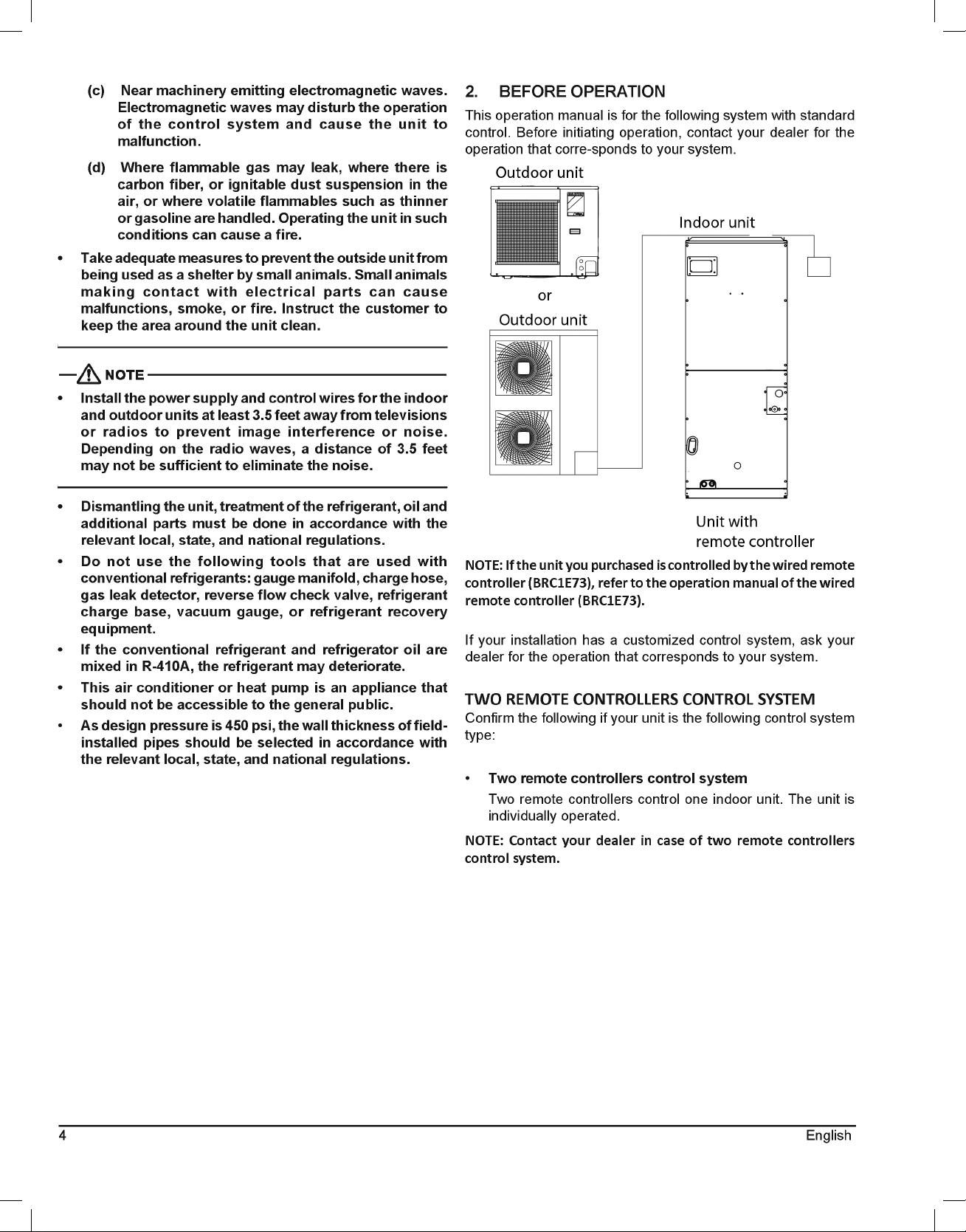
2. BEFORE OPERATION
This operation manual is for the following system with standard
control. Before initiating operation, contact your dealer for the
operation that corre-sponds to your system.
NOTE: If the unit you purchased is controlled by the wired remote
controller (BRC1E73), refer to the operation manual of the wired
remote controller (BRC1E73).
If your installation has a customized control system, ask your
dealer for the operation that corresponds to your system.
TWO REMOTE CONTROLLERS CONTROL SYSTEM
Confirm the following if your unit is the following control system
type:
• Two remote controllers control system
Two remote controllers control one indoor unit. The unit is
individually operated.
NOTE: Contact your dealer in case of two remote controllers
control system.
5
English
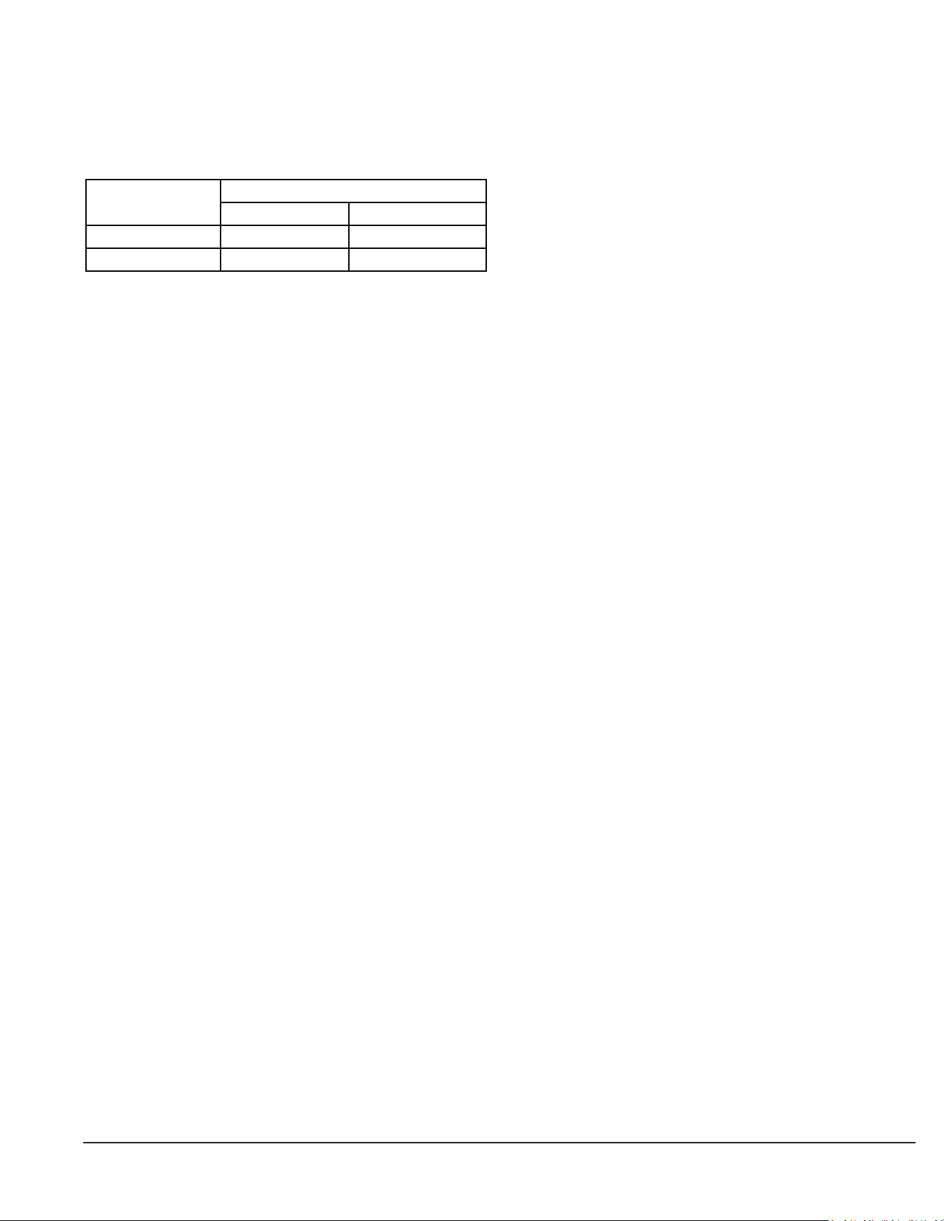
3. OPERATION RANGE
If the temperature or the humidity is beyond the “following
conditions, safety devices may work and the air conditioner or
heat pump may not operate, or sometimes, water may drop from
the indoor unit.
OUTDOOR INDOOR
COOLING 23 TO 122 (DB) 57.2 TO 77 (WB)
HEATING -4 TO 60 (WB) 59 TO 80.6 (DB)
OPERATION
TEMPERATURE (°F)
DB: Dry Bulb Temperature
WB: Wet Bulb Temperature
The setting temperature range of the remote controller is 60°F
to 90°F.
4. INSTALLATION SITE
Regarding places for installation:
• Is the air conditioner or heat pump installed at a well-
ventilated place where there are no obstacles around?
• Do not use the air conditioner or heat pump in the
following places:
a. An atmosphere laden with mineral oil
b. Places with an abundance of salt such as coastal areas
c. Where sulfured gas exists such as a hot spring resort
d. Where there are considerable voltage fluctuations
such as a factory or plant
e. Vehicles and vessels
f. A place like a kitchen with a lot of oil and vapor
g. Where there are machines generating electromagnetic
waves
h. An areas filled with acid and/or alkaline steam or vapor
• Is a snow protection measure taken?
For details, consult your dealer.
Regarding wiring:
• All wiring must be performed by an authorized
electrician.
To do wiring, ask your dealer. Never do it by yourself.
• Make sure that a separate power supply circuit is
provided for this air conditioner or heat pump and that
all electrical work is carried out by qualified personnel
according to local laws and regulations.
Pay attention to the installation location:
• Are the followlng places selected?
a. A place that can sufficiently withstand the weight of
the air conditioner or heat pump with minimal vibration
and operation sound.
b. A place where the air discharged from the outlet of
the outdoor unit and the running sound do not become
bothersome.
• Are you sure that there are no obstacles near the air
outlet of the outdoor unit?
Such obstacles may result in declined performance and
increased running sound.
• If abnormal sounds occur in use, stop the operation of
the air conditioner or heat pump and consult your dealer.
Regarding drainage of drain piping:
• Is the drain piping executed to perform complete
drainage?
If proper drainage is not carried out from the outdoor drain
pipes during air-conditioning operation, chances are that dust
and dirt are clogged in the pipe. This may result in a water
leakage from the indoor unit. Under such circumstances, stop
the operation of the air conditioner or heat pump, and then
consult your dealer or our service station.
6 English
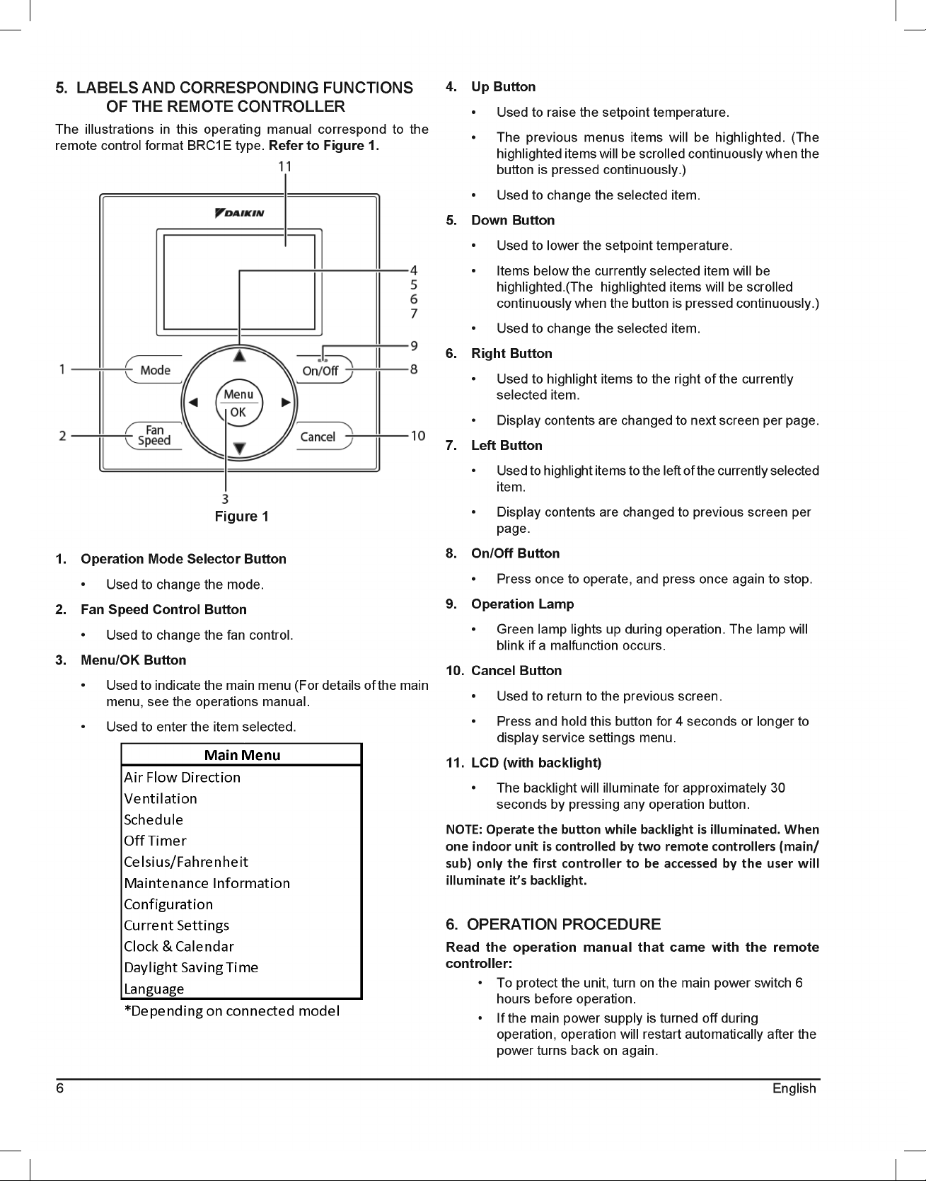
5. LABELS AND CORRESPONDING FUNCTIONS
OF THE REMOTE CONTROLLER
The illustrations in this operating manual correspond to the
remote control format BRC1E type. Refer to Figure 1.
Figure 1
1. Operation Mode Selector Button
• Used to change the mode.
2. Fan Speed Control Button
• Used to change the fan control.
3. Menu/OK Button
• Used to indicate the main menu (For details of the main
menu, see the operations manual.
• Used to enter the item selected.
Configuration
Current Settings
Clock & Calendar
Daylight Saving Time
Language
*Depending on connected model
Main Menu
Air Flow Direction
Ventilation
Schedule
Off Timer
Celsius/Fahrenheit
Maintenance Information
4. Up Button
• Used to raise the setpoint temperature.
• The previous menus items will be highlighted. (The
highlighted items will be scrolled continuously when the
button is pressed continuously.)
• Used to change the selected item.
5. Down Button
• Used to lower the setpoint temperature.
• Items below the currently selected item will be
highlighted.(The highlighted items will be scrolled
continuously when the button is pressed continuously.)
• Used to change the selected item.
6. Right Button
• Used to highlight items to the right of the currently
selected item.
• Display contents are changed to next screen per page.
7. Left Button
• Used to highlight items to the left of the currently selected
item.
• Display contents are changed to previous screen per
page.
8. On/Off Button
• Press once to operate, and press once again to stop.
9. Operation Lamp
• Green lamp lights up during operation. The lamp will
blink if a malfunction occurs.
10. Cancel Button
• Used to return to the previous screen.
• Press and hold this button for 4 seconds or longer to
display service settings menu.
11. LCD (with backlight)
• The backlight will illuminate for approximately 30
seconds by pressing any operation button.
NOTE: Operate the button while backlight is illuminated. When
one indoor unit is controlled by two remote controllers (main/
sub) only the first controller to be accessed by the user will
illuminate it’s backlight.
6. OPERATION PROCEDURE
Read the operation manual that came with the remote
controller:
• To protect the unit, turn on the main power switch 6
hours before operation.
• If the main power supply is turned off during
operation, operation will restart automatically after the
power turns back on again.
7
English
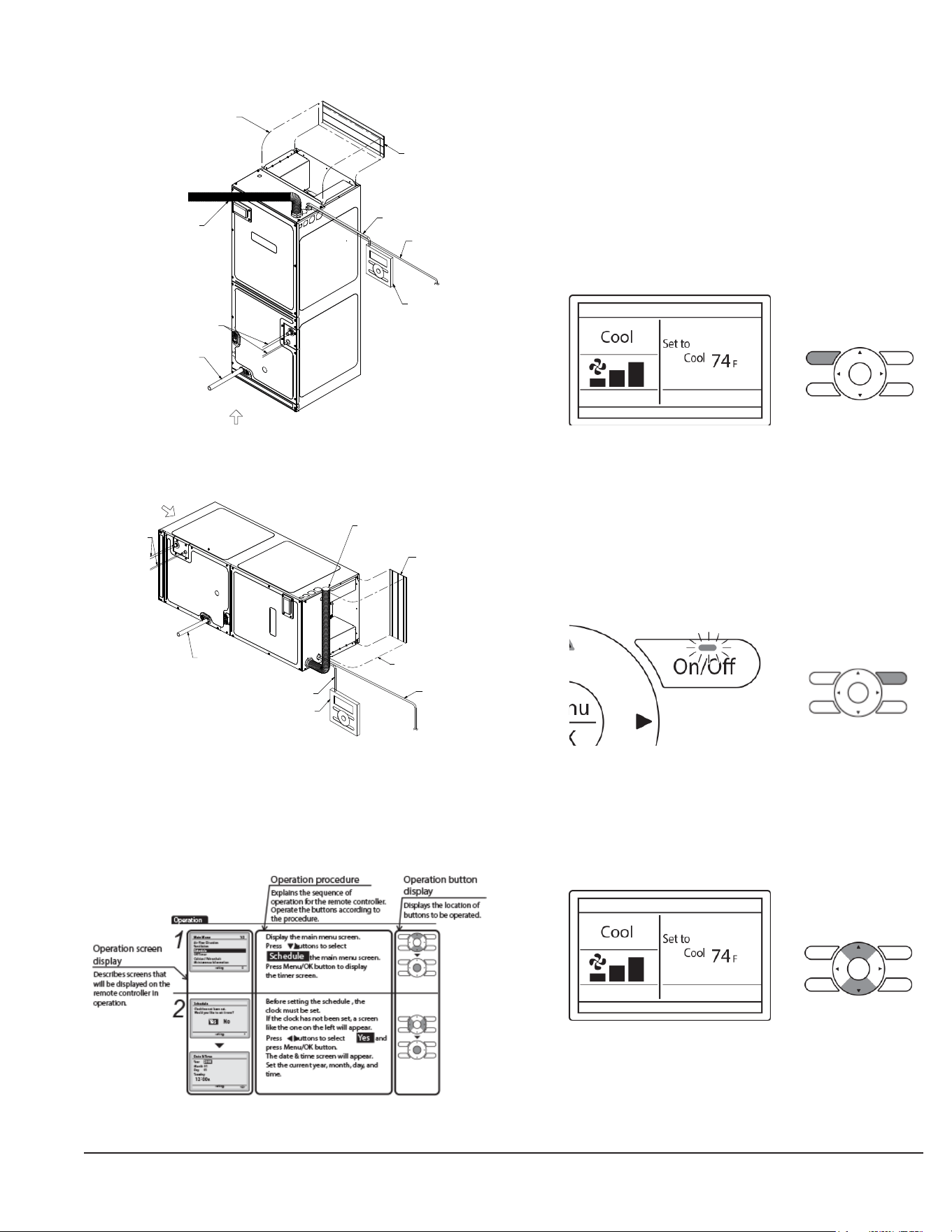
Part Name and Functions
In case of vertical position:
Transmission Wiring
Air inlet
Air outlet
(local procurment)
Power supply wiring and
Ground wire through conduit
Refrigerant piping
Drain pipe
Airflow duct
(local procurment)
Connecting Wire
Remote Controller
VERTICAL POSITION
Figure 2
In case of horizontal position:
Air inlet
Transmission Wiring
HORIZONTAL POSITION
(local procurment)
Power supply wiring and
Ground wire through conduit
Refrigerant piping
Drain pipe
Airflow duct
(local procurment)
Connecting Wire
Remote Controller
Air outlet
Figure 3
Basic Operation
COOL/HEAT/AUTO/FAN OPERATION
How to follow the operation manual:
Preparation:
• For mechanical protection purposes, apply power to the
outdoor units at least six hours before starting the opeartion
of the system.
Operation
1. Press the Operation mode selector button several times until
the desired mode Cool, Heat, Fan, or Auto mode is
selected.(Unavailable operation modes are not displayed.)
NOTE: Before changing the mode, confirm that the display does
not indicate master controlled status. Both heat and cool mode
may not be selected if the unit is master controlled.
2. Press On/Off button. The Operation lamp (green) will
illuminate and the system will start operating.
3. The setpoint will increase by 1°F (or 1°C) when the Up Button
is pressed and decrease by 1°F (or 1°C) when the Down
Button is pressed. Setpoint is not available in fan or dry mode.
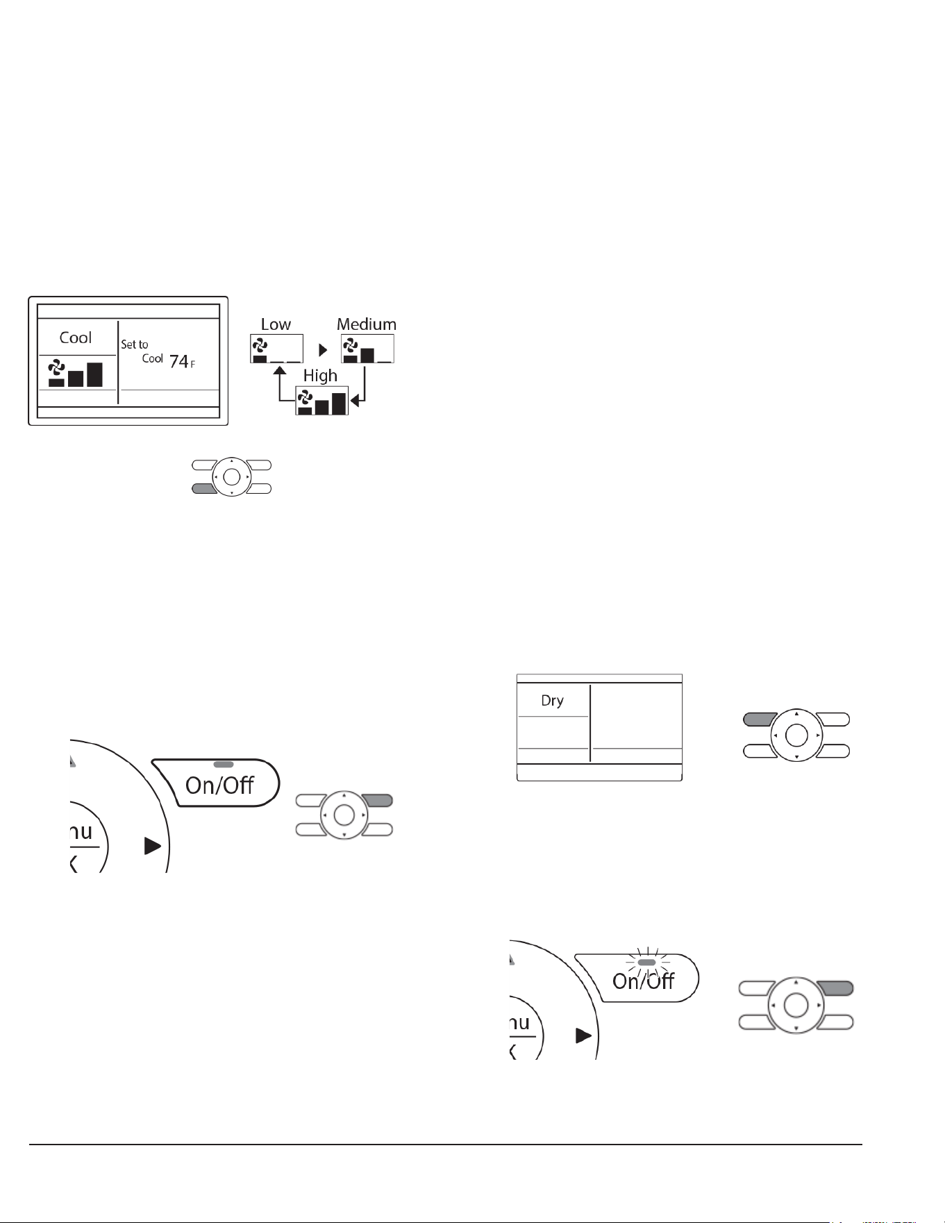
8 English
4. To change the fan speed, press the Fan speed control button
and select the desired fan speed from Low, Medium, or High.
• Only two fan speed adjustment levels, low and high may
be available depending on the type of Indoor unit.
• The system may be in automatic fan speed control for
equipment protection purposes.
• The system may be in automatic fan speed control
according to the room temperature. It is normal for the
fan to intermittently stop operating.
• It is normal for a delay to occur when changing the
fan speed.
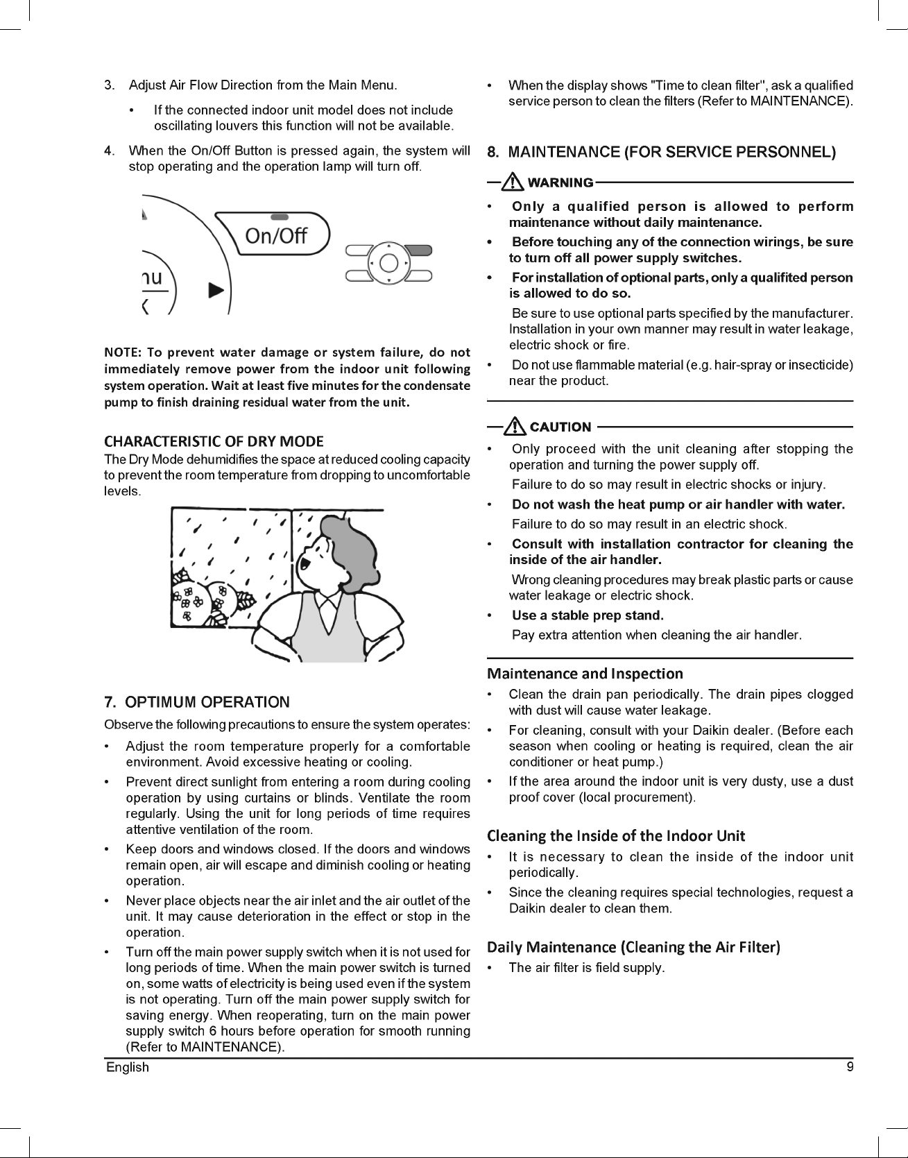
5. Adjust Air Flow Direction from the Main Menu.
• If the connected indoor unit model does not include
oscillating louvers this function will not be available.
6. When the On/Off Button is pressed again, the system will
stop operating and the operation lamp will turn off.
• When the system is stopped while in the heating mode,
the fan will continue to operate for approximately one
minute to remove residual heat from the indoor unit.
NOTE: To prevent water damage or system failure, do not
immediately remove power from the indoor unit following
system operation. Wait at least five minutes for the condensate
pump to finish draining residual water from the unit.
CHARACTERISTICS OF HEAT MODE
The system automatically controls the following operating modes
to prevent the reduction of heating capacity and space comfort.
Defrost Operation
• The system will automatically go into defrost operation to
prevent frost accumulation at the outdoor unit and loss of
heating capacity.
• The indoor unit fan will stop, and “STANDBY” (Defrost/Hot
Start) will be displayed on the remote controller.
• The system will return to normal operation usually within six
to eight minutes (but not more than 10 minutes).
Hot Start
• When the system goes into heat mode, the indoor unit fan
will stop in order to prevent a cold draft. (In that case,
“STANDBY” (Defrost/Hot Start) will be displayed on the
remote controller).
DRY MODE
Preparation
• For equipment protection purposes, apply power to the
outdoor units at least six hours before“starting the operation
of the system.
• The dry mode may not be selected if the remote controller is
master controlled and the system is not already in the cooling
mode of operation.
Operation
1. Press Mode Button several times until the Dry mode is
selected. (The Dry mode may not be available depending
on the type of indoor unit.)
2. Press On/Off Button. The Operation Lamp (green) will
illuminate and the system will start operating. In Dry Mode,
the system maintains automatic temperature and fan speed
control. Therefore, temperature setpoint or fan speed
settings are not available while the indoor unit is in the Dry
Mode.
9
English
3. Adjust Air Flow Direction from the Main Menu.
• If the connected indoor unit model does not include
oscillating louvers this function will not be available.
4. When the On/Off Button is pressed again, the system will
stop operating and the operation lamp will turn off.
NOTE: To prevent water damage or system failure, do not
immediately remove power from the indoor unit following
system operation. Wait at least five minutes for the condensate
pump to finish draining residual water from the unit.
CHARACTERISTIC OF DRY MODE
The Dry Mode dehumidifies the space at reduced cooling capacity
to prevent the room temperature from dropping to uncomfortable
levels.
7. OPTIMUM OPERATION
Observe the following precautions to ensure the system operates:
• Adjust the room temperature properly for a comfortable
environment. Avoid excessive heating or cooling.
• Prevent direct sunlight from entering a room during cooling
operation by using curtains or blinds. Ventilate the room
regularly. Using the unit for long periods of time requires
attentive ventilation of the room.
• Keep doors and windows closed. If the doors and windows
remain open, air will escape and diminish cooling or heating
operation.
• Never place objects near the air inlet and the air outlet of the
unit. It may cause deterioration in the effect or stop in the
operation.
• Turn off the main power supply switch when it is not used for
long periods of time. When the main power switch is turned
on, some watts of electricity is being used even if the system
is not operating. Turn off the main power supply switch for
saving energy. When reoperating, turn on the main power
supply switch 6 hours before operation for smooth running
(Refer to MAINTENANCE).
• When the display shows "Time to clean filter'', ask a qualified
service person to clean the filters (Refer to MAINTENANCE).
8. MAINTENANCE (FOR SERVICE PERSONNEL)
• Only a qualified person is allowed to perform
maintenance without daily maintenance.
• Before touching any of the connection wirings, be sure
to turn off all power supply switches.
• For installation of optional parts, only a qualifited person
is allowed to do so.
Be sure to use optional parts specified by the manufacturer.
Installation in your own manner may result in water leakage,
electric shock or fire.
• Do not use flammable material (e.g. hair-spray or insecticide)
near the product.
• Only proceed with the unit cleaning after stopping the
operation and turning the power supply off.
Failure to do so may result in electric shocks or injury.
• Do not wash the heat pump or air handler with water.
Failure to do so may result in an electric shock.
• Consult with installation contractor for cleaning the
inside of the air handler.
Wrong cleaning procedures may break plastic parts or cause
water leakage or electric shock.
• Use a stable prep stand.
Pay extra attention when cleaning the air handler.
Maintenance and Inspection
• Clean the drain pan periodically. The drain pipes clogged
with dust will cause water leakage.
• For cleaning, consult with your Daikin dealer. (Before each
season when cooling or heating is required, clean the air
conditioner or heat pump.)
• If the area around the indoor unit is very dusty, use a dust
proof cover (local procurement).
Cleaning the Inside of the Indoor Unit
• It is necessary to clean the inside of the indoor unit
periodically.
• Since the cleaning requires special technologies, request a
Daikin dealer to clean them.
Daily Maintenance (Cleaning the Air Filter)
• The air filter is field supply.
10 English
EXPLANATION:
• Removing the air filter except when cleaning the air
conditioner or heat pump may result in accidents.
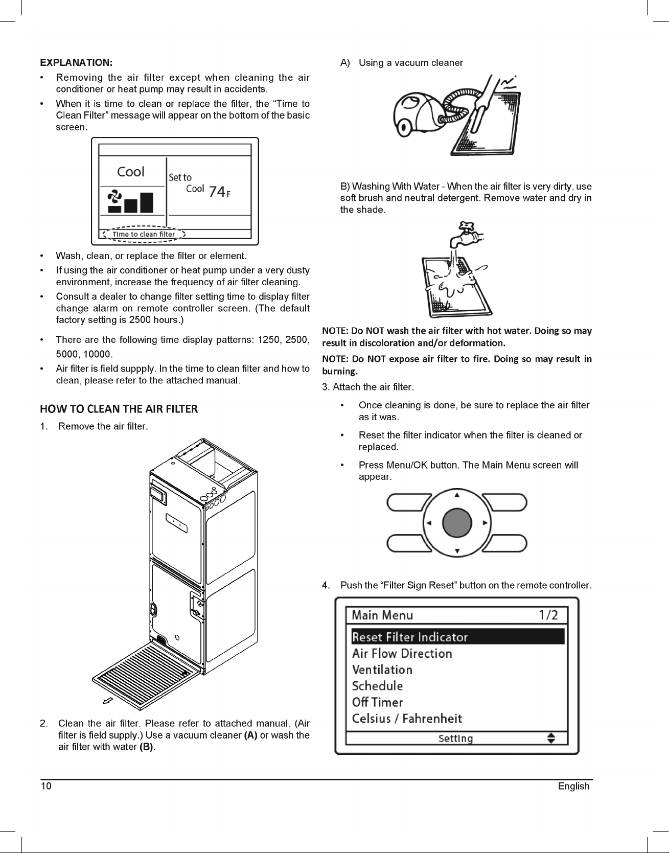
• When it is time to clean or replace the filter, the “Time to
Clean Filter” message will appear on the bottom of the basic
screen.
• Wash, clean, or replace the filter or element.
• If using the air conditioner or heat pump under a very dusty
environment, increase the frequency of air filter cleaning.
• Consult a dealer to change filter setting time to display filter
change alarm on remote controller screen. (The default
factory setting is 2500 hours.)
• There are the following time display patterns: 1250, 2500,
5000, 10000.
• Air filter is field suppply. In the time to clean filter and how to
clean, please refer to the attached manual.
HOW TO CLEAN THE AIR FILTER
1. Remove the air filter.
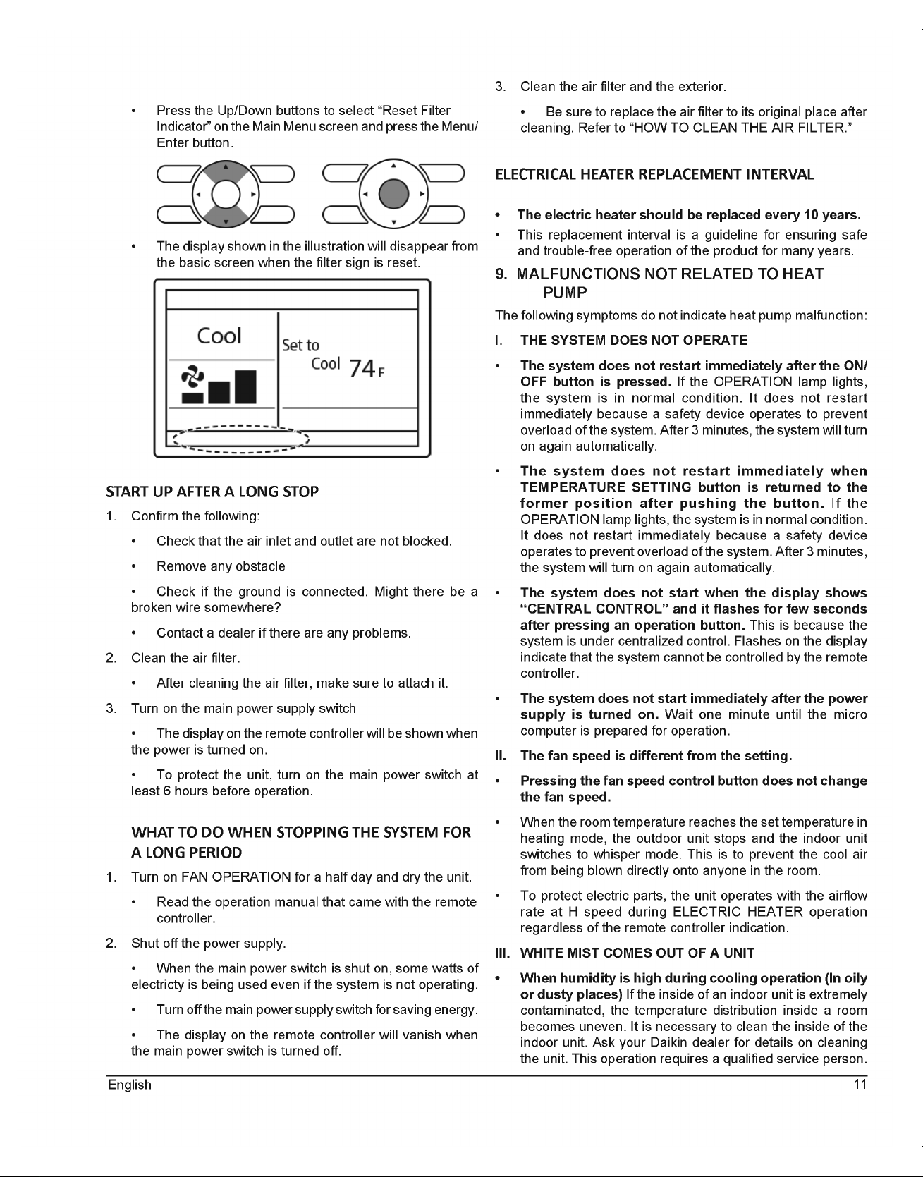
2. Clean the air filter. Please refer to attached manual. (Air
filter is field supply.) Use a vacuum cleaner (A) or wash the
air filter with water (B).
A) Using a vacuum cleaner
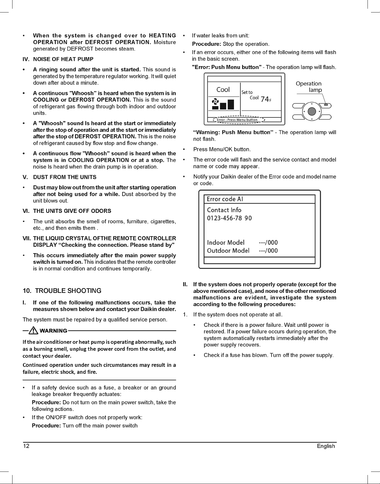
B) Washing With Water - When the air filter is very dirty, use
soft brush and neutral detergent. Remove water and dry in
the shade.
NOTE: Do NOT wash the air filter with hot water. Doing so may
result in discoloration and/or deformation.
NOTE: Do NOT expose air filter to fire. Doing so may result in
burning.
3. Attach the air filter.
• Once cleaning is done, be sure to replace the air filter
as it was.
• Reset the filter indicator when the filter is cleaned or
replaced.
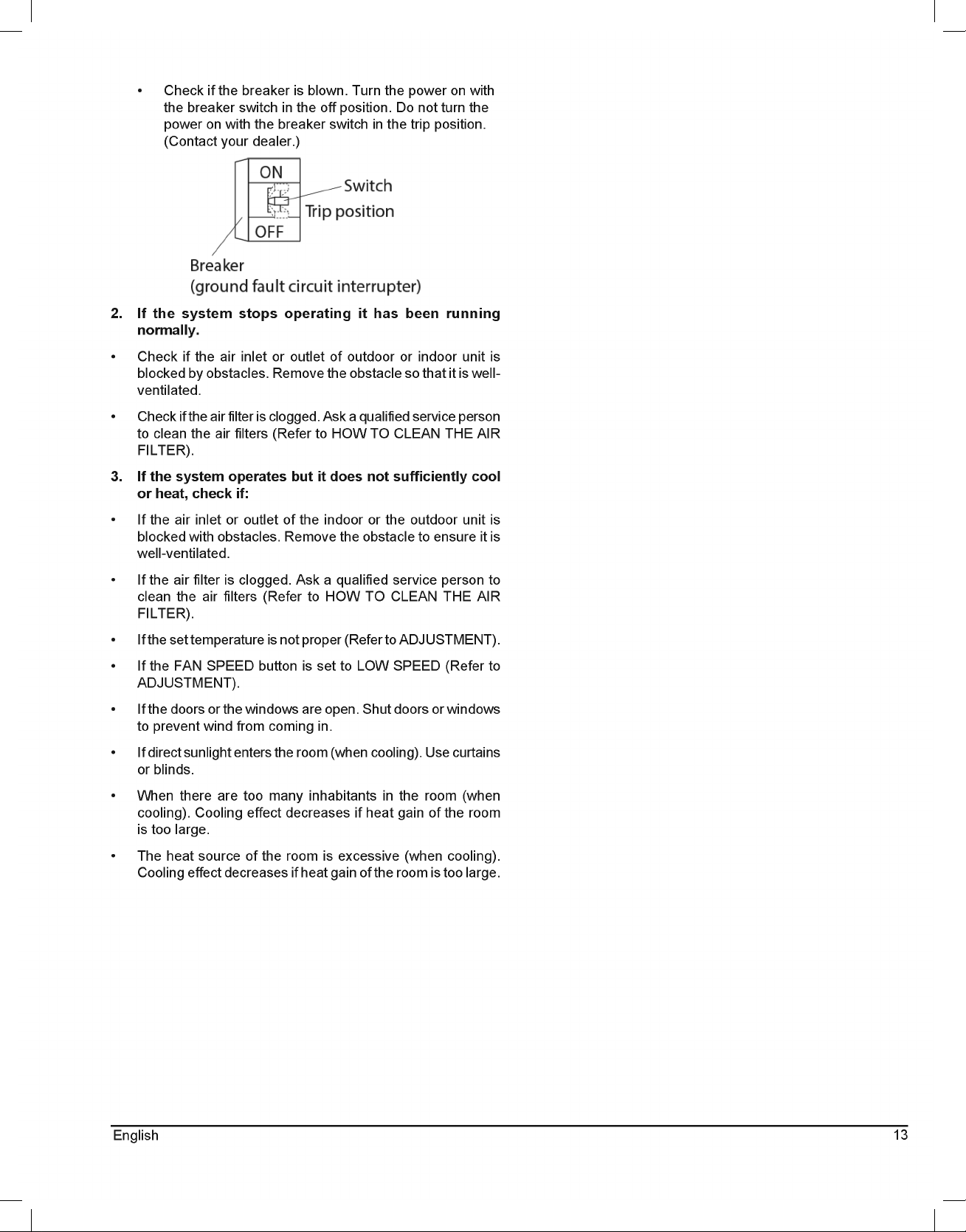
• Press Menu/OK button. The Main Menu screen will
appear.
4. Push the “Filter Sign Reset” button on the remote controller.
11
English
• Press the Up/Down buttons to select “Reset Filter
Indicator” on the Main Menu screen and press the Menu/
Enter button.
• The display shown in the illustration will disappear from
the basic screen when the filter sign is reset.
START UP AFTER A LONG STOP
1. Confirm the following:
• Check that the air inlet and outlet are not blocked.
• Remove any obstacle
• Check if the ground is connected. Might there be a
broken wire somewhere?
• Contact a dealer if there are any problems.
2. Clean the air filter.
• After cleaning the air filter, make sure to attach it.
3. Turn on the main power supply switch
• The display on the remote controller will be shown when
the power is turned on.
• To protect the unit, turn on the main power switch at
least 6 hours before operation.
WHAT TO DO WHEN STOPPING THE SYSTEM FOR
A LONG PERIOD
1. Turn on FAN OPERATION for a half day and dry the unit.
• Read the operation manual that came with the remote
controller.
2. Shut off the power supply.
• When the main power switch is shut on, some watts of
electricty is being used even if the system is not operating.
• Turn off the main power supply switch for saving energy.
• The display on the remote controller will vanish when
the main power switch is turned off.
3. Clean the air filter and the exterior.
• Be sure to replace the air filter to its original place after
cleaning. Refer to “HOW TO CLEAN THE AIR FILTER.”
ELECTRICAL HEATER REPLACEMENT INTERVAL
• The electric heater should be replaced every 10 years.
• This replacement interval is a guideline for ensuring safe
and trouble-free operation of the product for many years.
9. MALFUNCTIONS NOT RELATED TO HEAT
PUMP
The following symptoms do not indicate heat pump malfunction:
I. THE SYSTEM DOES NOT OPERATE
• The system does not restart immediately after the ON/
OFF button is pressed. If the OPERATION lamp lights,
the system is in normal condition. It does not restart
immediately because a safety device operates to prevent
overload of the system. After 3 minutes, the system will turn
on again automatically.
• The system does not restart immediately when
TEMPERATURE SETTING button is returned to the
former position after pushing the button. If the
OPERATION lamp lights, the system is in normal condition.
It does not restart immediately because a safety device
operates to prevent overload of the system. After 3 minutes,
the system will turn on again automatically.
• The system does not start when the display shows
“CENTRAL CONTROL” and it flashes for few seconds
after pressing an operation button. This is because the
system is under centralized control. Flashes on the display
indicate that the system cannot be controlled by the remote
controller.
• The system does not start immediately after the power
supply is turned on. Wait one minute until the micro
computer is prepared for operation.
II. The fan speed is different from the setting.
• Pressing the fan speed control button does not change
the fan speed.
• When the room temperature reaches the set temperature in
heating mode, the outdoor unit stops and the indoor unit
switches to whisper mode. This is to prevent the cool air
from being blown directly onto anyone in the room.
• To protect electric parts, the unit operates with the airflow
rate at H speed during ELECTRIC HEATER operation
regardless of the remote controller indication.
III. WHITE MIST COMES OUT OF A UNIT
• When humidity is high during cooling operation (In oily
or dusty places) If the inside of an indoor unit is extremely
contaminated, the temperature distribution inside a room
becomes uneven. It is necessary to clean the inside of the
indoor unit. Ask your Daikin dealer for details on cleaning
the unit. This operation requires a qualified service person.
12 English
• When the system is changed over to HEATING
OPERATION after DEFROST OPERATION. Moisture
generated by DEFROST becomes steam.
IV. NOISE OF HEAT PUMP
• A ringing sound after the unit is started. This sound is
generated by the temperature regulator working. It will quiet
down after about a minute.
• A continuous "Whoosh" is heard when the system is in
COOLING or DEFROST OPERATION. This is the sound
of refrigerant gas flowing through both indoor and outdoor
units.
• A "Whoosh" sound Is heard at the start or immediately
after the stop of operation and at the start or immediately
after the stop of DEFROST OPERATION. This is the noise
of refrigerant caused by flow stop and flow change.
• A continuous flow "Whoosh" sound is heard when the
system is in COOLING OPERATION or at a stop. The
noise ls heard when the drain pump is in operation.
V. DUST FROM THE UNITS
• Dust may blow out from the unit after starting operation
after not being used for a while. Dust absorbed by the
unit blows out.
VI. THE UNITS GIVE OFF ODORS
• The unit absorbs the smell of rooms, furniture, cigarettes,
etc., and then emits them .
VII. THE LIQUID CRYSTAL OFTHE REMOTE CONTROLLER
DISPLAY “Checking the connection. Please stand by"
• This occurs immediately after the main power supply
switch is turned on. This indicates that the remote controller
is in normal condition and continues temporarily.
10. TROUBLE SHOOTING
I. If one of the following malfunctions occurs, take the
measures shown below and contact your Daikin dealer.
The system must be repaired by a qualified service person.
If the air conditioner or heat pump is operating abnormally, such
as a burning smell, unplug the power cord from the outlet, and
contact your dealer.
Continued operation under such circumstances may result in a
failure, electric shock, and fire.
• If a safety device such as a fuse, a breaker or an ground
leakage breaker frequently actuates:
Procedure: Do not turn on the main power switch, take the
following actions.
• If the ON/OFF switch does not properly work:
Procedure: Turn off the main power switch
• If water leaks from unit:
Procedure: Stop the operation.
• If an error occurs, either one of the following items will flash
in the basic screen.
"Error: Push Menu button" - The operation lamp will flash.
“Warning: Push Menu button” - The operation lamp will
not flash.
• Press Menu/OK button.
• The error code will flash and the service contact and model
name or code may appear.
• Notify your Daikin dealer of the Error code and model name
or code.
II. If the system does not properly operate (except for the
above mentioned case), and none of the other mentioned
malfunctions are evident, investigate the system
according to the following procedures:
1. If the system does not operate at all.
• Check if there is a power failure. Wait until power is
restored. If a power failure occurs during operation, the
system automatically restarts immediately after the
power supply recovers.
• Check if a fuse has blown. Turn off the power supply.
13
English
• Check if the breaker is blown. Turn the power on with
the breaker switch in the off position. Do not turn the
power on with the breaker switch in the trip position.
(Contact your dealer.)
2. If the system stops operating it has been running
normally.
• Check if the air inlet or outlet of outdoor or indoor unit is
blocked by obstacles. Remove the obstacle so that it is well-
ventilated.
• Check if the air filter is clogged. Ask a qualified service person
to clean the air filters (Refer to HOW TO CLEAN THE AIR
FILTER).
3. If the system operates but it does not sufficiently cool
or heat, check if:
• If the air inlet or outlet of the indoor or the outdoor unit is
blocked with obstacles. Remove the obstacle to ensure it is
well-ventilated.
• If the air filter is clogged. Ask a qualified service person to
clean the air filters (Refer to HOW TO CLEAN THE AIR
FILTER).
• If the set temperature is not proper (Refer to ADJUSTMENT).
• If the FAN SPEED button is set to LOW SPEED (Refer to
ADJUSTMENT).
• If the doors or the windows are open. Shut doors or windows
to prevent wind from coming in.
• If direct sunlight enters the room (when cooling). Use curtains
or blinds.
• When there are too many inhabitants in the room (when
cooling). Cooling effect decreases if heat gain of the room
is too large.
• The heat source of the room is excessive (when cooling).
Cooling effect decreases if heat gain of the room is too large.
14 English
THIS PAGE IS INTENTIONALLY LEFT BLANK
15
English
THIS PAGE IS INTENTIONALLY LEFT BLANK
16 English
AIR HANDLER
AIR HANDLER HOMEOWNER’S ROUTINE MAINTENANCE RECOMMENDATIONS
We strongly recommend a bi-annual maintenance checkup be performed before the heating and cooling seasons begin by a qualified servicer.
REPLACE OR CLEAN FILTER
IMPORTANT NOTE: Never operate unit without a filter installed as dust and lint will build up on internal parts resulting in loss of efficiency,
equipment damage and possible fire.
An indoor air filter must be used with your comfort system. A properly maintained filter will keep the indoor coil of your comfort system clean.
A dirty coil could cause poor operation and/or severe equipment damage.
Your air filter or filters could be located in your furnace, in a blower unit, or in “filter grilles” in your ceiling or walls. The installer of your air
conditioner or heat pump can tell you where your filter(s) are, and how to clean or replace them.
Check your filter(s) at least once a month. When they are dirty, replace or clean as required. Disposable type filters should be replaced.
Reusable type filters may be cleaned.
You may want to ask your dealer about high efficiency filters. High efficiency filters are available in both electronic and non-electronic types.
These filters can do a better job of catching small airborne particles.
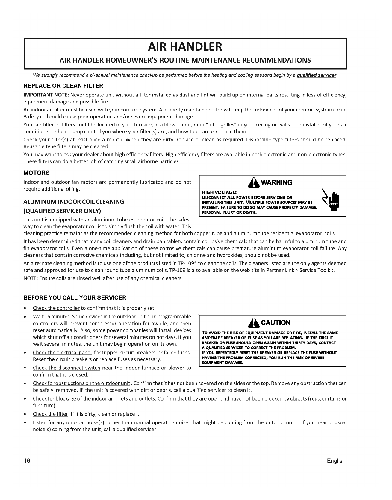
MOTORS
Indoor and outdoor fan motors are permanently lubricated and do not
require additional oiling.
ALUMINUM INDOOR COIL CLEANING
(QUALIFIED SERVICER ONLY)
This unit is equipped with an aluminum tube evaporator coil. The safest
way to clean the evaporator coil is to simply flush the coil with water. This
cleaning practice remains as the recommended cleaning method for both copper tube and aluminum tube residential evaporator coils.
It has been determined that many coil cleaners and drain pan tablets contain corrosive chemicals that can be harmful to aluminum tube and
fin evaporator coils. Even a one-time application of these corrosive chemicals can cause premature aluminum evaporator coil failure. Any
cleaners that contain corrosive chemicals including, but not limited to, chlorine and hydroxides, should not be used.
An alternate cleaning method is to use one of the products listed in TP-109* to clean the coils. The cleaners listed are the only agents deemed
safe and approved for use to clean round tube aluminum coils. TP-109 is also available on the web site in Partner Link > Service Toolkit.
NOTE: Ensure coils are rinsed well after use of any chemical cleaners.
BEFORE YOU CALL YOUR SERVICER
• Check the controller to confirm that it is properly set.
•
Wait 15 minutes. Some devices in the outdoor unit or in programmable
controllers will prevent compressor operation for awhile, and then
reset automatically. Also, some power companies will install devices
which shut off air conditioners for several minutes on hot days. If you
wait several minutes, the unit may begin operation on its own.
•
Check the electrical panel for tripped circuit breakers or failed fuses.
Reset the circuit breakers or replace fuses as necessary.
•
Check the disconnect switch near the indoor furnace or blower to
confirm that it is closed.
•
Check for obstructions on the outdoor unit . Confirm that it has not been covered on the sides or the top. Remove any obstruction that can
be safely removed. If the unit is covered with dirt or debris, call a qualified servicer to clean it.
•
Check for blockage of the indoor air inlets and outlets. Confirm that they are open and have not been blocked by objects (rugs, curtains or
furniture).
•
Check the filter. If it is dirty, clean or replace it.
•
Listen for any unusual noise(s), other than normal operating noise, that might be coming from the outdoor unit. If you hear unusual
noise(s) coming from the unit, call a qualified servicer.