USER MANUAL
RESIDENTIAL USE ONLY
ADDRESS OF YOUR INSTALLER
23130 REV. 04
HRV150FL AND HRV190FL
VB0298
2
ABOUT THIS MANUAL / PRODUCT
The purpose of this manual is to help you with the use of your unit. Please read every section as
they contain important information.
In simplifying explanations, all drawings (illustrations) in this manual show the unit installed in the
“normal” position. However, please note that your unit can be installed in either the “normal” or
“reverse” (upside down) position.
We welcome any suggestions you may have concerning this manual and/or the unit, and we would
appreciate hearing your comments on ways to better serve you. Please forward all correspondence
to us at the address indicated on the product’s registration card included with this manual.
This manual uses the following symbols to emphasize particular information:
NOTE: Indicates supplementary information needed to fully complete an instruction.
Finally, we want to congratulate you on your purchase of this excellent unit which will allow you and
your family to enjoy fresh air throughout your home for years to come!
Identifies an instruction which, if not followed, might cause serious personal
injuries including possibility of death.
Denotes an instruction which, if not followed, may severely damage the unit and/
or its components.
WARNING
!
Some activities create dust or vapors which may damage your unit. You must
therefore turn off and unplug your unit in the following situations:
• Major renovation work • Sanding (e.g. gypsum joints, etc.)
• Housing construction • Varnishing
During very heavy snowstorms or rain with strong winds, the unit should also
be turned off to avoid problems caused by snow or rain entering the unit, even if
it is equipped with an anti-gust intake hood.
REPLACEMENT PARTS AND REPAIRS
In order to ensure your ventilation unit remains in good working condition, you must use Broan-
NuTone LLC genuine replacement parts only. The Broan-NuTone LLC genuine replacement
parts are specially designed for each unit and are manufactured to comply with all the applicable
certification standards and maintain a high standard of safety. Any third party replacement part
used may cause serious damage and drastically reduce the performance level of your unit,
which will result in premature failing. Also, Broan-NuTone LLC recommends to contact a certified
service depot for all replacement parts and repairs.
CAUTION
CAUTION
CAUTION
When leaving the house for a long period of time (more than two weeks), a
responsible person should regularly check if the unit operates adequately. If
the ductwork runs through an unconditioned space (e.g.: attic), the unit must
operate continuously except when performing maintenance and/or repair. Also,
the ambient temperature of the house should never drop below 18°C (65°F). At
least once a year, the unit mechanical and electronic parts should be inspected
by qualified service personnel.

3
TABLE OF CONTENTS
1. YOUR UNIT AND ITS PURPOSE ......................................4
1.2 PURPOSE OF THE VENTILATION SYSTEM ..................................4
1.3 RECOVERY ..................................................................................... 5
1.4 DEFROST MODE ............................................................................ 5
1.5 SPECIFICATIONS ...........................................................................5
2. CONTROLS .......................................................................6
2.1 INTEGRATED CONTROL ............................................................... 6
2.2 BOOT SEQUENCE ......................................................................... 6
2.3 OPTIONAL MAIN AND AUXILIARY CONTROLS ............................ 6
3. MAINTENANCE ................................................................7
3.1 EVERY THREE MONTHS ............................................................... 7
3.2 ANNUAL MAINTENANCE (FALL) ................................................... 8
4. TROUBLESHOOTING .......................................................8
4
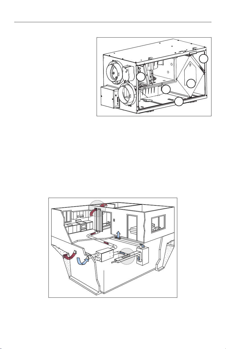
1. YOUR UNIT AND ITS PURPOSE
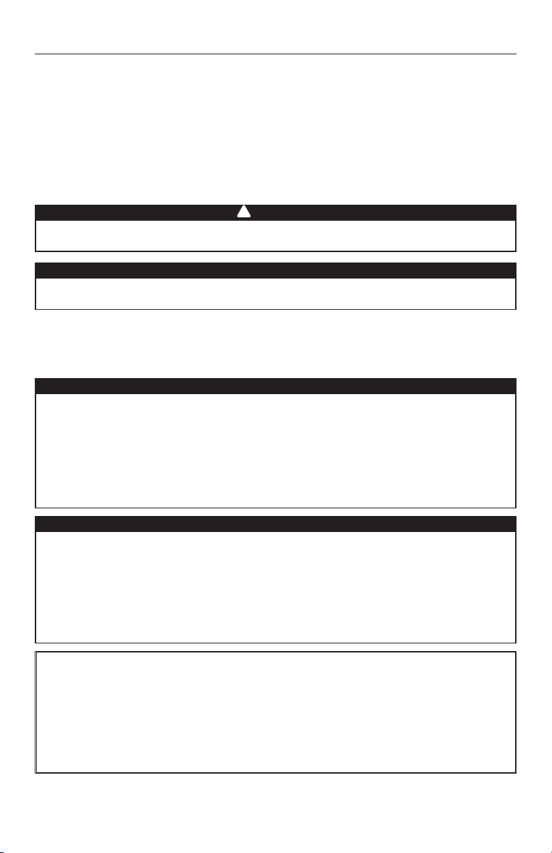
1. Filters
2. Blower
3. Heat recovery core
4. Condensation tray
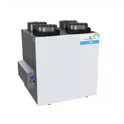
1.1 UNIT DESCRIPTION
Unit shown in normal position. Can also be installed upside down.
Your ventilation system is designed to provide fresh air, warmed outdoor air to your home while
exhausting stale, humid air from your home. By eliminating accumulated pollutants and humidity, it
maintains an optimum air quality and an ideal relative humidity.
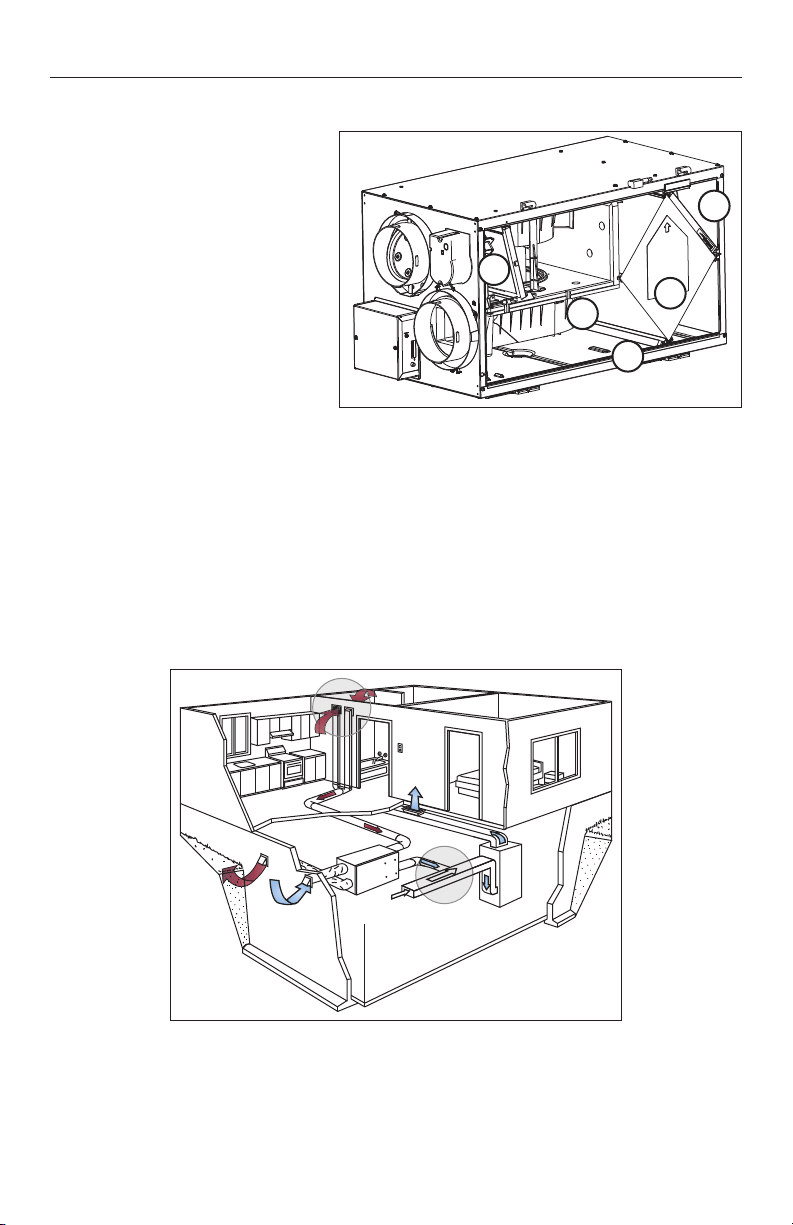
1.2 PURPOSE OF THE VENTILATION SYSTEM
VH0078
NOTES: 1. Shown with a forced air system. Can also operate on its own.
2. Installation may vary according to the model number and the position (normal or
reverse) in which the unit is installed.
VL0052
1
1
2
3
4
5
Your ventilation system is equipped with a heat recovery core that is designed specifically to control
excess humidity and reduce ventilation costs by recovering the heat energy from the exhausted air,
and using that same heat energy to warm the fresh air being supplied. This heat recovery process
is accomplished in such a way that the stale air is never mixed with the fresh air.
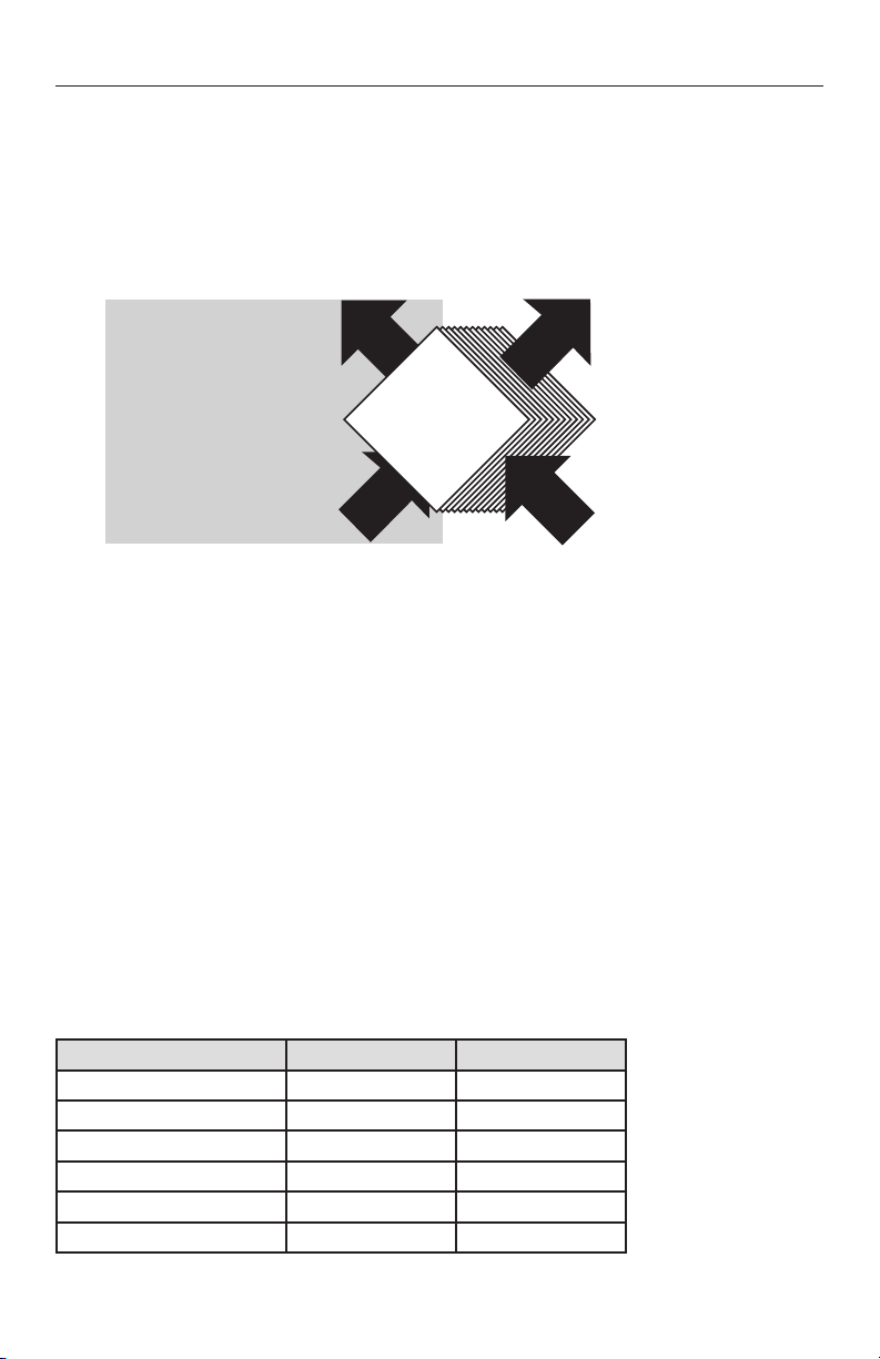
1.3 RECOVERY
EXAMPLE (IN WINTER)
VF0026
OUTDOORS
INDOOR
When the outdoor temperature is below -5°C (23°F), heat recovery creates frost in the module.
To maintain proper operation, the unit is programmed to defrost the recovery module. The defrost
frequency varies according to the outdoor temperature. Defrost lasts 7 minutes (or 10 minutes if set
on “Extented Defrost”). During the defrost cycle, the unit shifts to maximum speed and the dampers
close.
After defrosting, the unit returns to the operating mode selected by the user.
1.4 DEFROST MODE
MODEL HRV150FL HRV190FL
WIDTH 30¼" 30¼"
HEIGHT 16½" 16½"
D
EPTH 178" 178"
W
EIGHT 65 LB. (29.5 KG) 65 LB. (29.5 KG)
ELECTRICAL SUPPLY 120 V, 60 HZ 120 V, 60 HZ
POWER CONSUMPTION 160 WATTS 195 WATTS
1.5 SPECIFICATIONS
Stale air to outdoors
6°C/42°F
Fresh air from outdoors
0°C/32°F
Fresh air to building
16°C/61°F
Stale air from building
22°C/72°F
1. YOUR UNIT AND ITS PURPOSE (CONT’D)
6
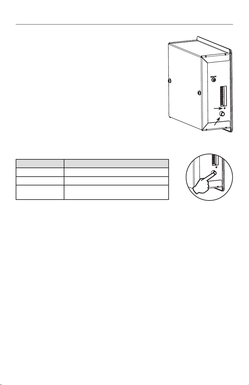
2. CONTROLS
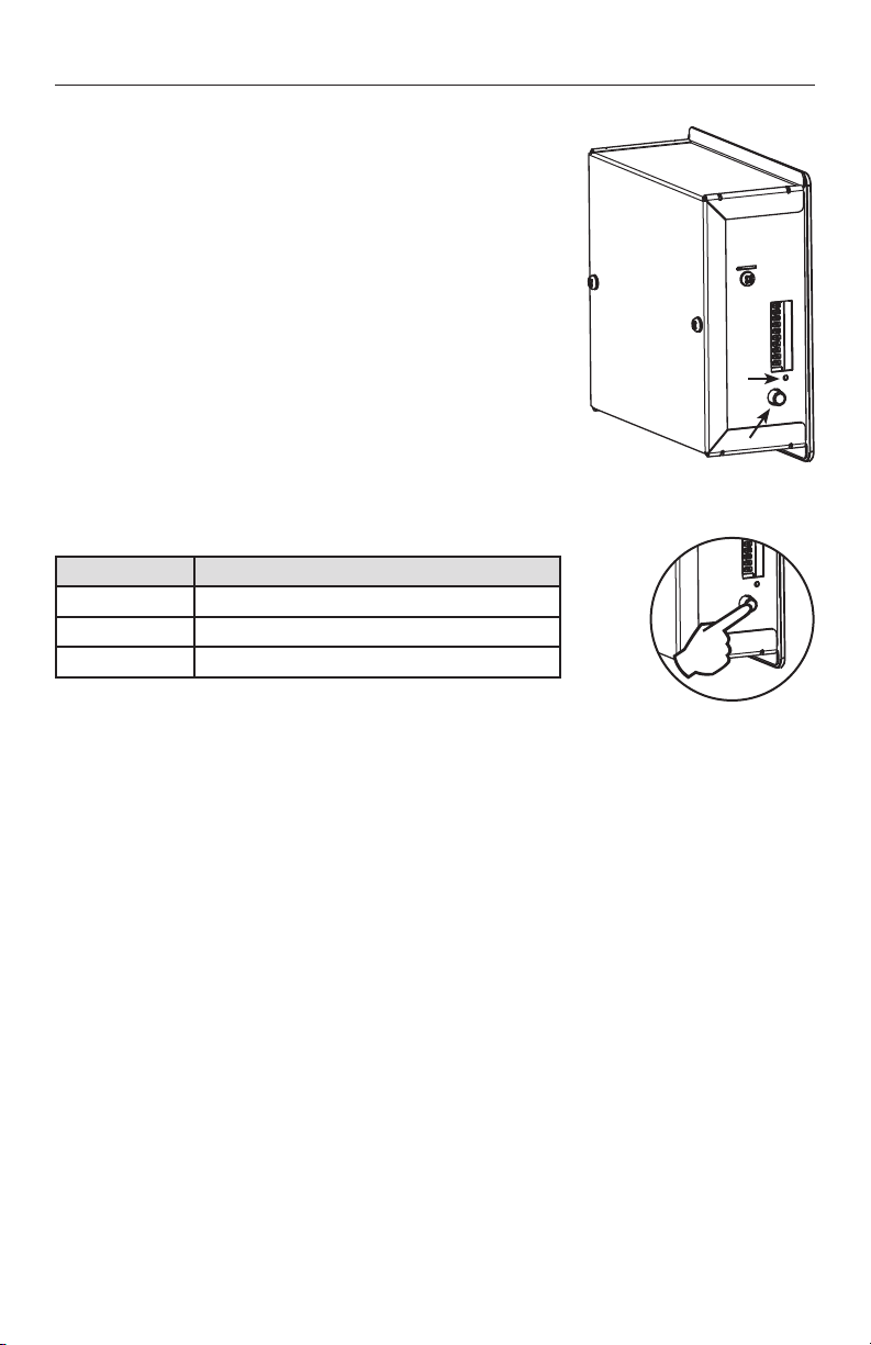
These units are equipped with an integrated control, located on the
electrical compartment. Use the push-button (1) to control the unit.
The LED (2) will then show on which mode the unit is in.
NOTES: 1. The integrated control must be turned OFF to use an
optional main control.
2. If an optional auxiliary control is used, if activated, the
auxiliary control operation will override the optional
main control operation.
2.1 INTEGRATED CONTROL
VD0278
1
2
VD0281
Refer to table below.
LED COLOR RESULTS
AMBER UNIT IS ON LOW SPEED.
GREEN UNIT IS ON HIGH SPEED.
NO LIGHT UNIT IS OFF OR CONTROLLED BY A MAIN CONTROL.
The unit boot sequence is similar to a personnal computer boot sequence. Each time the unit is
plugged after being unplugged, or after a power failure, the unit will perform a 30-second booting
sequence before starting to operate. During the booting sequence, the integrated control LED will
light GREEN or AMBER for 5 seconds, and then will shut off for 2 seconds. After that, the LED will
light RED for the rest of the booting sequence. During this RED light phase, the unit is checking and
resetting the motorized damper position. Once the motorized damper position is completely set, the
RED light turns off and the booting sequence is done.
NOTE: No command will be taken until the unit is fully booted.
2.2 BOOT SEQUENCE
2.3 OPTIONAL MAIN AND AUXILIARY CONTROLS
For more convenience, these units can also be controlled using an optional main wall control. Many
models can be used, but only one main wall control can be connected to the unit.
NOTES: 1. The integrated control must be turned OFF to use an optional main control.
2. If an optional auxiliary control is used, if activated, the auxiliary control operation will
override the optional main control operation.
For more information about the available controls and their operation modes, refer to the Main
and auxiliary wall control User Guide (included with the ventilation unit and also available at
www.broan.com)
7
3. MAINTENANCE
Dangerous voltage may be present. During maintenance and repairs, the unit
must always be turned off, and unplugged.
We take great care to minimize sharp edges; however, please proceed with
caution when handling all components.
When cleaning the unit, it is recommended to wear safety glasses and gloves.
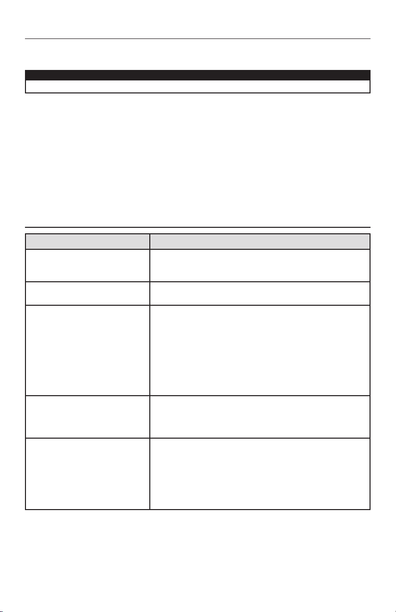
3.1 EVERY THREE MONTHS
Regular maintenance should be performed every 3 months. Annual maintenance should take place
every fall season.
NOTE: Unit is shown in normal position but can be installed in either the “normal” or “reverse”
(upside down) position.
WARNING
!
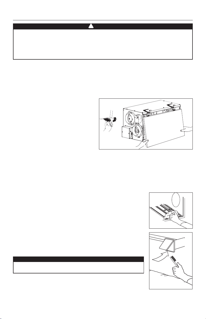
1. Disconnect power supply.
2. Unlatch the door. Lift the panel towards
you. Hold it firmly and hit on the right side
of the panel. The door will slide to the left.
3. Clean the inside of the door with a damp cloth.
4. Clean filters:
• Remove filters.
• Vacuum to remove most of the dust.
• Wash with a mixture of warm water and mild soap. You may add bleach if you wish to disinfect
(one tablespoon per gallon). Rinse thoroughly. Shake filters to remove excess water and let dry.
5. Clean the condensation tray with a damp cloth.
6. Check the exterior air intake hood:
• Make sure there are no leaves, twigs, ice or snow that could be
drawn into the vent.
• Clean if necessary.
7. Reassemble the components.
8. Reconnect power supply.
CAUTION
Even a partial blocking of this air vent could cause the unit
to malfunction.
VO0229
VD0035
VO0230
8
3. MAINTENANCE (CONT’D)
3.2 ANNUAL MAINTENANCE (FALL)
Repeat steps 1 to 6 from the previous section and continue with the following steps:
1. Clean the heat recovery core:
• Remove core.
• Let it soak in a mixture of cold or lukewarm water and mild soap (dishwashing liquid).
• Rinse thoroughly.
• Shake the core to remove excess water and let it dry.
2. Clean blower assembly.
• Remove dust using a vacuum cleaner with a soft brush attachment.
3. Reassemble the components.
4. Reconnect power supply.
CAUTION
Handle the heat recovery core with care.
4. TROUBLESHOOTING
PROBLEM YOU SHOULD TRY THIS
1. Nothing works. • See if the unit is plugged in.
• See if the unit is receiving power from the house
circuit breaker or fuse.
2. Noisy unit. • Clean the unit (see Section 3). If the problem is not
solved, contact your installer.
3. Condensation on windows (air too
humid).
• Operate the unit at maximum speed (MAX.) during
activities generating excess humidity (family
gatherings, extra cooking, etc.).
• Leave curtains half-open to allow air circulation.
• Store all firewood in a closed room with a dehumidifier
or in a well ventilated room, or store the wood outdoors.
• Keep the temperature in your house above
18°C (64°F).
4. Air too dry. • Operate the unit at low speed (MIN.).
• Temporarily switch to the intermittent mode (if
available).
• Temporarily use a humidifier.
5. Air too cold at the air supply grille. • Make sure the outdoor hoods are not blocked.
• Operate the unit at low speed (MIN.).
• Have the system’s balancing checked.
• Have the unit’s defrost system checked.
• Install a duct heater.
For wall controls problems, refer to the Troubleshooting section in the Main and auxiliary wall
controls user guide (included with the ventilation unit and also available at www.broan.com).
If the problem is still not solved, contact your installer.

MANUAL DEL USUARIO
PARA USO RESIDENCIAL ÚNICAMENTE
DIRECCIÓN DE SU INSTALADOR
HRV150FL Y HRV190FL
VB0298
23130 REV. 04
2
ACERCA DE ESTE MANUAL / PRODUCTO
El propósito de este manual es ayudarle en el uso del aparato. Por favor, lea cada sección ya que
contiene información importante.
Para simplificar las explicaciones, todos los dibujos (ilustraciones) en este manual muestran
el aparato instalado en posición «normal». No obstante, tenga en cuenta que el aparato puede
instalarse en posición «normal» o «invertida» (boca abajo).
Agradecemos cualquier sugerencia que usted pueda tener acerca de este manual y/o del aparato
y agradeceríamos recibir sus comentarios sobre la forma de ofrecerle mejor servicio. Por favor,
transmita toda la correspondencia a la dirección indicada en la tarjeta de registro del producto que
se incluye con este manual.
Este manual utiliza los siguientes símbolos para hacer hincapié en determinada información:
NOTA: Indica la información complementaria necesaria para completar una instrucción.
Por último, queremos felicitarlo por la compra de este excelente aparato que le permitirá a usted y
a su familia disfrutar de aire fresco en su hogar durante los próximos años.
Identifica una instrucción que, si no se sigue, puede causar lesiones perso-
nales graves, incluso causar la muerte.
ADVERTENCIA
!
Algunas actividades crean polvo o vapores que podrían dañar el aparato. Por
lo tanto, debe apagar y desenchufar el aparato en las siguientes situaciones:
• Obras de renovación importantes • Lijado (p. ej., juntas de yeso, etc.)
• Construcción de vivienda • Barnizado
Durante las tormentas de nieve muy fuertes o lluvia con fuertes vientos, también
debería apagarse el aparato para evitar los problemas que podría causar la
entrada de lluvia o nieve en él, incluso si está equipado con una boca de entrada
antirráfagas.
REPUESTOS Y REPARATIONES
Para que el aparato de ventilación esté en buenas condiciones, sólo debe utilizar repuestos
Broan-NuTone LLC genuinos. Los repuestos Broan-NuTone LLC genuinos han sido diseñados
especialmente para cada aparato, han sido fabricados de conformidad con todas las normas
de certificación aplicables y ofrecen un alto nivel de seguridad. El uso de repuestos diferentes
puede provocar daños graves y reducir drásticamente el nivel de rendimiento del aparato, lo cual
podría causar una avería prematura. Asimismo, Broan-NuTone LLC recomienda ponerse en
contacto con un almacén de servicio certificado para todos los repuestos y reparaciones.
Designa una instrucción que, si no se sigue, puede dañar gravemente el aparato
y/o sus componentes.
PRECAUCIÓN
PRECAUCIÓN
PRECAUCIÓN
Al ausentarse de la vivienda durante un periodo largo (más de dos semanas),
una persona responsable debería verificar regularmente si el aparato funciona
correctamente. Si los conductos pasan a través de un espacio no acondicionado
(como un desván), el aparato debe funcionar constantemente, excepto cuando
haya que hacer tareas de mantenimiento o reparaciones. Asimismo, la
temperatura ambiente de la casa nunca debería bajar de 18°C (65°F). Al menos
una vez al año, personal de servicio cualificado debería examinar las piezas
mecánicas y electrónicas del aparato.

3
ÍNDICE
1. SU APARATO Y SU OBJETIVO ........................................4
1.1 DESCRIPCIÓN DEL APARATO .......................................................4
1.2 PROPÓSITO DEL SISTEMA DE VENTILACIÓN ............................ 4
1.3 RECUPERACIÓN ............................................................................ 5
1.4 MODO DESCONGELACIÓN ........................................................... 5
1.5 ESPECIFICACIONES ...................................................................... 5
2. CONTROLES ....................................................................6
2.1 CONTROL INTEGRADO ................................................................ 6
2.2 SECUENCA DE PUESTA EN MARCHA ......................................... 6
2.3 CONTROLES PRINCIPALES Y AUXILIARES OPCIONALES ........ 6
3. MANTENIMIENTO ............................................................7
3.1 MANTENIMIENTO TRIMESTRIAL .................................................. 7
3.2 MANTENIMIENTO ANUAL (OTOÑO) ............................................. 8
4. SOLUCIÓN DE PROBLEMAS ..........................................8
4
1. SU APARATO Y SU OBJETIVO
1. Filtros
2. Ventilador impelente
3. Unidad de recuperación de calor
4. Bandeja de condensación
1.1 DESCRIPCIÓN DEL APARATO
El aparato se muestra en posición normal. También puede instalarse en posición invertida.
El sistema de ventilación está pensado para proporcionar a su hogar aire fresco y aire caliente
del exterior, expulsando al mismo tiempo el aire viciado y húmedo de su vivienda. Al eliminar la
humedad y los contaminantes acumulados, el sistema mantiene un aire de calidad óptima y una
humedad relativa ideal.
1.2 PROPÓSITO DEL SISTEMA DE VENTILACIÓN
VH0078
NOTAS: 1. Se muestra con un sistema de aire forzado. También puede funcionar de forma
autónoma.
2. La instalación puede variar según el número de modelo y la posición (normal o
invertida) en la que se instale el aparato
VL0052
1
1
2
3
4

5
El sistema de ventilación está equipado con una unidad de recuperación de calor que está pensada
específicamente para controlar el exceso de humedad y reducir los costos de ventilación mediante
la recuperación de la energía calorífica del aire expulsado, y para usar esa misma energía calorífica
para calentar el aire fresco que suministra. Este proceso de recuperación de calor se realiza de tal
modo que el aire viciado nunca se mezcla con el aire fresco.
1.3 RECUPERACIÓN
EJEMPLO (EN INVIERNO)
VF0026
EXTERIOR
INTERIOR
Cuando la temperatura exterior es inferior a -5°C (23°F), la recuperación del calor forma escarcha
en el módulo. Para mantener el buen funcionamiento, el aparato está programado para descongelar
el módulo de recuperación. La frecuencia de descongelación varía según la temperatura exterior.
La descongelación dura 7 minutos (o 10 minutos si el aparato ha sido configurado en modo
«descongelación ampliada»). Durante el ciclo de descongelación, el aparato pasa a la velocidad
máxima y las compuertas se cierran.
Tras la descongelación, el aparato vuelve al modo de funcionamiento seleccionado por el usuario.
1.4 MODO DESCONGELACIÓN
MODELO HRV150FL HRV190FL
ANCHURA 30 ¼" 30 ¼"
ALTURA 16 ½" 16 ½"
P
ROFUNDIDAD 17 18" 17 18"
P
ESO 65 LB. (29,5 KG) 65 LB. (29,5 KG)
ALIMENTACIÓN ELÉCTRICA 120 V, 60 HZ 120 V, 60 HZ
CONSUMO ELÉCTRICO 160 VATIOS 195 VATIOS
1.5 ESPECIFICACIONES
Aire viciado hacia el
exterior
6°C/42°F
Aire fresco del exterior
0°C/32°F
Aire fresco hacia el
edificio
16°C/61°F
Aire viciado del
edificio
22°C/72°F
1. SU APARATO Y SU OBJETIVO (CONT.)
6
2. CONTROLES
Estos aparatos están equipados con un control integrado situado
sobre el compartimento eléctrico. Utilice el botón pulsador (1) para
controlar el aparato. El diodo LED (2) le indicará el modo en el que
funciona el aparato.
NOTAS : 1. Para utilizar el control principal opcional, el control
integrado debe estar apagado.
2. Si se utiliza un control auxiliar opcional, al activarlo,
anula el control principal opcional.
2.1 CONTROL INTEGRADO
VD0278
1
2
VD0281
Consulte la tabla siguiente.
COLOR DEL LED RESULTADOS
ÁMBAR El aparato está en velocidad baja.
VERDE El aparato está en velocidad alta.
NINGUNA LUZ
El aparato está apagado o controlado por un
control principal.
La secuencia de puesta en marcha del aparato es similar a la de una computadora personal.
Cada vez que se enchufa el aparato tras haberse desenchufado o tras una interrupción de la
alimentación eléctrica, el aparato inicia una secuencia de puesta en marcha de unos 30 segundos
antes de empezar a funcionar. Durante la secuencia de puesta en marcha, el diodo (LED) del
control integrado se encenderá de color VERDE o ÁMBAR durante 5 segundos y luego se apagará
durante 2 segundos. A continuación, el LED se encenderá en ROJO durante el resto de la secuencia
de puesta en marcha. Mientras el LED está en ROJO, el aparato verifica y reconfigura la posición
de la compuerta motorizada. Una vez establecida la posición de la compuerta motorizada, la luz
ROJA se apaga para indicar que la secuencia de puesta en marcha ha terminado.
NOTA: el aparato no acepta ninguna instrucción hasta que se haya puesto en marcha totalmente.
2.2 SECUENCA DE PUESTA EN MARCHA
2.3 CONTROLES PRINCIPALES Y AUXILIARES OPCIONALES
Para mayor comodidad, estos aparatos también pueden controlarse mediante un control mural
principal opcional. Se pueden usar muchos modelos pero únicamente puede conectarse al aparato
un solo control mural principal.
NOTAS: 1. Para utilizar el control principal opcional, el control integrado debe estar apagado.
2. Si se utiliza un control auxiliar opcional, al activarlo, anula el control principal opcional.
Para obtener más información acerca de los controles disponibles y sus modos de funcionamiento,
consulte la Guía del usuario para los controles murales principales y auxiliares (incluida con el
aparato de ventilación y también disponible en www.broan.com)

7
3. MANTENIMIENTO
Posible presencia de voltaje peligroso. El aparato debe estar siempre apagado y
desenchufado durante las operaciones de mantenimiento y reparación.
Aunque procuramos minimizar los bordes cortantes, tenga cuidado al manipular
todos los componentes.
Al limpiar el aparato, se aconseja llevar lentes y guantes de seguridad.
3.1 MANTENIMIENTO TRIMESTRIAL
El mantenimiento regular debe realizarse cada 3 meses. El mantenimiento anual debe hacerse
cada otoño.
NOTA: aunque el aparato se muestra en posición normal, puede instalarse en posición «normal»
o «invertida» (boca abajo).
1. Desconecte la fuente de alimentación.
2. Abra la puerta. Levante el panel hacia
usted. Sujételo firmemente y golpee en
el lado derecho del panel. La puerta se
deslizará hacia la izquierda.
3. Limpie el interior de la puerta con un paño húmedo.
4. Limpie los filtros:
• Quite los filtros.
• Pase una aspiradora para quitar la mayor parte del polvo.
• Lave con una mezcla de agua tibia y jabón suave.Puede añadir blanqueador (lejía) si desea
desinfectar (una cucharada por galón). Enjuague a fondo. Agite los filtros para eliminar el
exceso de agua y déjelos secar.
5. Limpie la bandeja de condensación con un paño húmedo.
6. Verifique la boca de entrada de aire del exterior:
• Compruebe que no haya hojas, ramitas, hielo o nieve que podrían
entrar en el aparato.
• Limpie si es necesario.
7. Vuelva a montar los componentes.
8. Vuelva a conectar la fuente de alimentación.
PRECAUCIÓN
Un bloqueo parcial de este orificio de ventilación podría
hacer que el aparato funcionara mal.
VO0229
VD0035
VO0230
ADVERTENCIA
!
8
3. MANTENIMIENTO (CONT.)
3.2 MANTENIMIENTO ANUAL (OTOÑO)
Repita las etapas 1 a 6 de la sección anterior y continúe con las que se exponen a continuación:
1. Limpie la unidad de recuperación de calor:
• Retire la unidad.
• Déjela en remojo en una mezcla de agua fría o tibia y jabón suave (detergente para vajillas).
• Enjuague a fondo.
• Agite la unidad para eliminar el exceso de agua y déjela secar.
2. Limpie el conjunto del ventilador.
• Quite el polvo con una aspiradora equipada con un cepillo suave.
3. Vuelva a montar los componentes.
4. Vuelva a conectar la fuente de alimentación.
PRECAUCIÓN
Maneje con cuidado la unidad de recuperación de calor.
4. SOLUCIÓN DE PROBLEMAS
PROBLEMA INTENTE ESTO
1. Nada funciona. • Verifique si el aparato está enchufado.
• Compruebe si el aparato recibe alimentación del disyuntor
o del fusible de la casa.
2. Aparato ruidoso. • Limpie el aparato (véase la sección 3). Si el problema no se
soluciona, póngase en contacto con el instalador.
3. Condensación en las ventanas
(aire demasiado húmedo).
• Haga funcionar el aparato a velocidad máxima (MAX).
durante las actividades que generan exceso de humedad
(reuniones familiares, cocción excesiva, etc.).
• Deje las cortinas entreabiertas para que el aire circule.
• Guarde toda la leña en un cuarto cerrado equipado con
un deshumidificador, en un cuarto bien ventilado o en el
exterior.
• Mantenga la temperatura de su casa por encima de 18°C
(64°F).
4. Aire demasiado seco. • Haga funcionar el aparato a velocidad baja (MIN).
• Cambie temporalmente al modo intermitente (si está
disponible).
• Use temporalmente un humidificador.
5. Aire demasiado frío en la rejilla
de suministro de aire.
• Asegúrese de que las bocas exteriores no están
bloqueadas.
• Haga funcionar el aparato a velocidad baja (MIN).
• Haga que verifiquen el equilibrio del sistema.
• Haga que verifiquen el sistema de descongelación del
aparato.
• Instale un calentador de conductos.
Para los problemas de los controles murales, consulte la sección Solución de problemas en la Guía
del usuario para los controles murales principales y auxiliares (incluida en el aparato de ventilación
y también disponible en www.broan.com).
Si el problema no se soluciona, póngase en contacto con el instalador.