Loading ...
Loading ...
Loading ...
5
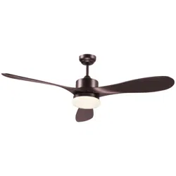
10. put the remote receiver into the middle of the bracket and connect the wires. (connect the wires according to the wiring
instructions)
power supply from ceiling (120V/60Hz)
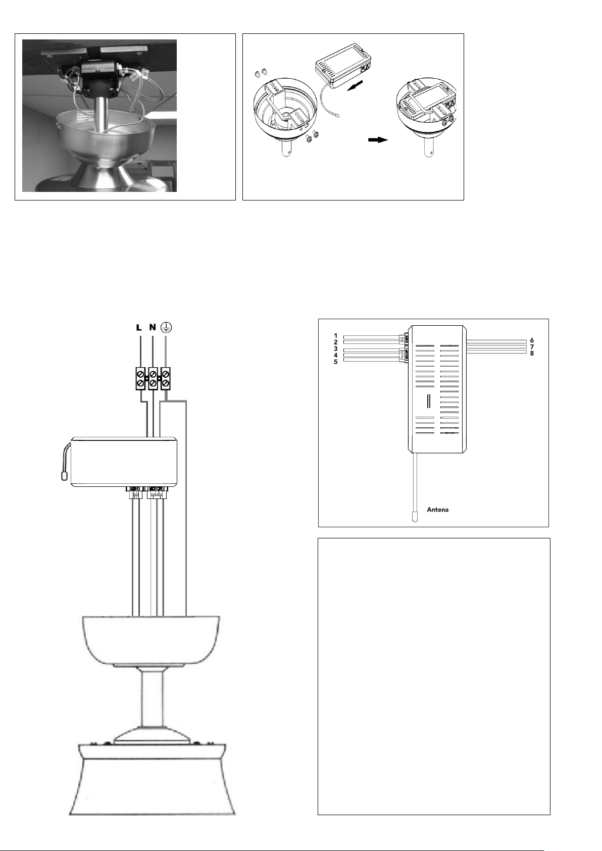
11. Remote control connection diagram.
The antenna don’t need be left outside the
outlet
Subtitle:
1: Light wire L (Blue)
2: Light wire N (White)
3: Motor phase wire U (Gray)
4: Motor phase wire V (Violet)
5: Motor phase wire W (Red)
6
:
AC IN L (Black)
7
:
AC IN N (White)
8
:
Ground wire (Green)
MOTOR
RECEIVER
Loading ...
Loading ...
Loading ...