Home
Bookmarks
Home
Bosch
Bosch DWG098D50I/02 User Manual
Page 5
Bosch DWG098D50I/02 Serie 2 Wall hood
User Manual - Page 5
For DWG098D50I/02.
PDF File Manual
,
8 pages
,
Read Online
|
Download pdf file
DWG068D50I, DWG098D50I, DWG068D60I, DWG098D60I
: Important safety information
Danger of death!
Risk of death!
Danger of suffocation!
Risk of electric shock!
Risk of fire!
Risk of fire!
Risk of injury!
Risk of injury!
Risk of injury!
General information
Exhaust air mode
Note
Exhaust duct
Note
Circulating-air mode
Note
Electrical connection
: Risk of electric shock!
Preparing for installation
Checking the wall
Appliance dimensions and safety clearances
Preparing the wall
Caution!
1. Mark a vertical centre line on the wall from the ceiling to the lower edge of the extractor hood. (Fig. 1)
2. Mark holes for the angle brackets in the flue. The centre of the angle brackets is marked with a notch. Centre the angle brackets using the centre line, position them horizontally and mark the positions of the holes.
3. Drill the holes.
4. Press in the wall plugs flush with the wall.
Fitting the wall bracket
Preparing the appliance
Installing the appliance
Attaching and aligning the appliance
: Risk of injury!
1. First remove the protective foil from the back of the appliance and, following installation, remove the foil completely.
2. Align the appliance horizontally. (Fig. 3a)
3. Mark the holes. (Fig. 4a)
4. Tighten the screws V. (Fig. 4b)
5. Drill the holes. (Fig. 5a)
6. Press in the wall plugs flush with the wall.
7. Screw on mounting brackets for the appliance.
8. Fit the appliance.
9. Align the appliance horizontally by turning the screws on the mounting brackets. The screws are accessible from the inside of the appliance. (Fig. 3b)
10. Tighten the screws. (Fig. 5b)
11. Loosen the screws V to adjust the appliance in height. (Fig. 5c)
12. Tighten the screws. (Fig. 5d)
13. Install the metal grease filters.
Connecting the appliance
Connecting the air extractor and establishing a connection to the mains
Notes
Connecting the exhaust air pipe
Note
1. Attach the exhaust air pipe directly to the air pipe connector. (Fig. 6a)
2. Connect it to the exhaust air opening.
3. Use suitable means to seal the joints.
Connecting the power supply
1. Plug the mains plug into the earthed socket. (Fig. 7)
2. If a fixed connection is required, follow the instructions in the Electrical connection section.
Installing the active carbon filter (only in circulating-air mode) (Fig. 6b)
1. Remove the metal grease filters.
2. Insert the new active carbon filter and secure it in place using the fastening hooks.
3. Fix the back flap on the exhaust and secure with clamping ring.
4. Mount the metal grease filters.
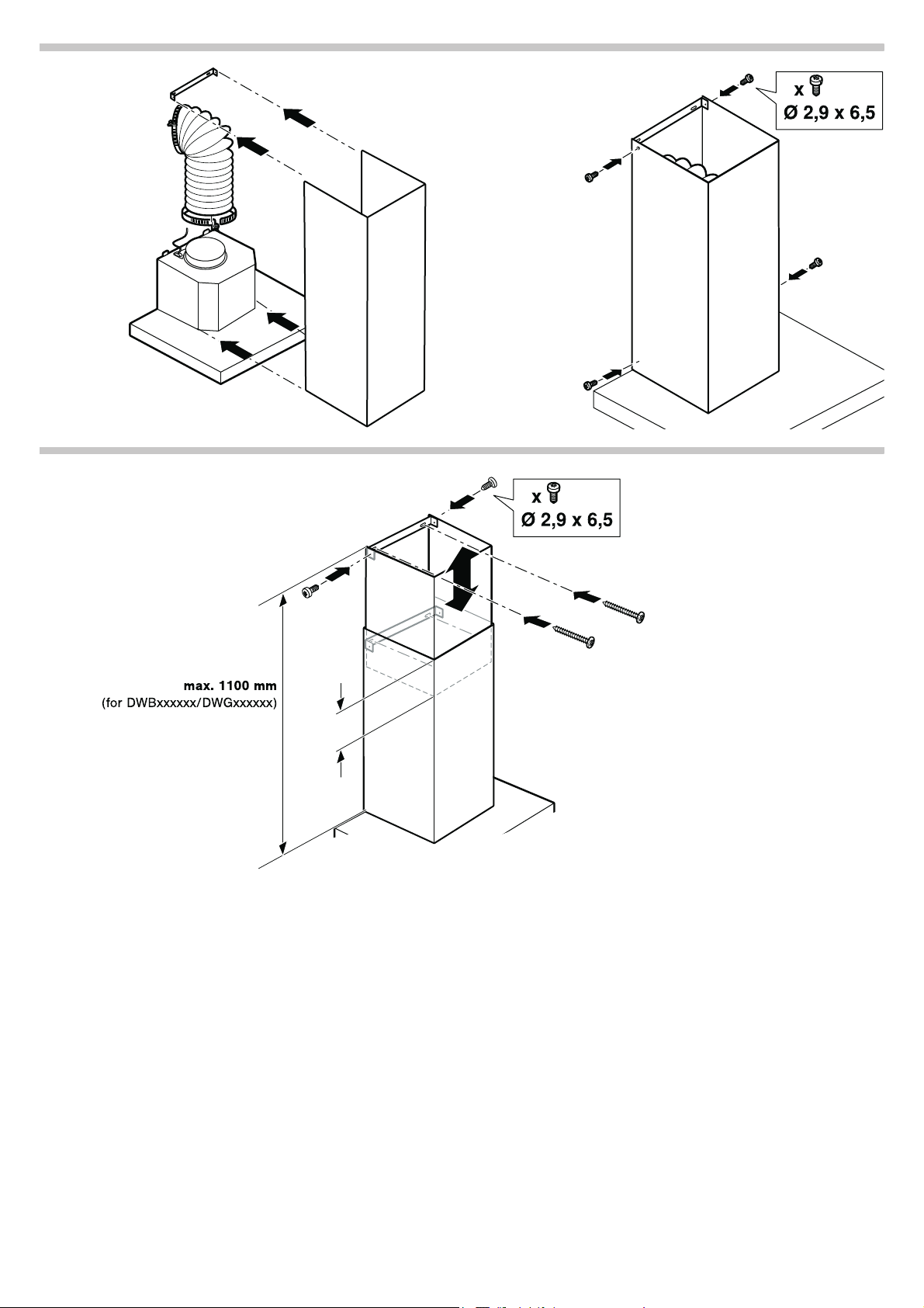
Attaching the flue duct
: Risk of injury!
1. Remove the pieces of protective film from the flue duct.
2. Place the flue duct on the appliance and fix it in place. Gently push the two side panels apart, hook them in behind the angle bracket and then push them back together as far as they will go (i.e. until they are touching the ends of the bracket). ...
3. Screw the flue duct to the ends of the angle bracket. (Fig. 8b)
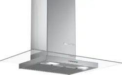
Installing the flue duct extension (Fig. 9)
: Risk of injury!
1. Remove the pieces of protective film from the flue duct extension.
2. Place the flue duct extension inside the flue duct. Gently push downward till touches the chimney body.
3. Fix the bottom angle bracket to the wall as shown in above figure.
4. Fix the top angle bracket as per the required height of flue duct extension as shown in above figure.
Note
5. Screw the flue duct extension to the ends of the angle bracket.
Removing the appliance
1. Disconnect the appliance from the power supply.
2. Remove the flue duct.
3. Loosen the exhaust air lines.
4. Remove the metal grease filter.
5. Unscrew in the screws for the appliance bracket slightly; do not loosen them fully.
6. Remove the appliance.
7. Remove the angle bracket for the flue duct.
Page 5/8
Page 1
Page 2
Page 3
Page 4
Page 5
Page 6
Page 7
Page 8
Contents
Table of Contents
Search
Previous
Next
Bookmarks
Loading ...
Loading ...
Loading ...
D
E
PL
Q
P
P
Loading ...
Loading ...
Loading ...
File type: PDF
File name: 44116301_dwg098d50i-01.pdf
File size: 583.26 KB
File Language: English
Pages: 8
Author: Bosch
File created: 2019-10-18
Published:
2023-11-04
Updated: 2023-11-04
Download File
Table of Contents
×
DWG068D50I, DWG098D50I, DWG068D60I, DWG098D60I
1
: Important safety information
6
Danger of death!
6
Risk of death!
6
Danger of suffocation!
6
Risk of electric shock!
6
Risk of fire!
6
Risk of fire!
6
Risk of injury!
6
Risk of injury!
6
Risk of injury!
7
General information
7
Exhaust air mode
7
Note
7
Exhaust duct
7
Note
7
Circulating-air mode
7
Note
7
Electrical connection
7
: Risk of electric shock!
7
Preparing for installation
7
Checking the wall
7
Appliance dimensions and safety clearances
7
Preparing the wall
7
Caution!
7
1. Mark a vertical centre line on the wall from the ceiling to the lower edge of the extractor hood. (Fig. 1)
7
2. Mark holes for the angle brackets in the flue. The centre of the angle brackets is marked with a notch. Centre the angle brackets using the centre line, position them horizontally and mark the positions of the holes.
7
3. Drill the holes.
7
4. Press in the wall plugs flush with the wall.
7
Fitting the wall bracket
7
Preparing the appliance
7
Installing the appliance
7
Attaching and aligning the appliance
7
: Risk of injury!
7
1. First remove the protective foil from the back of the appliance and, following installation, remove the foil completely.
7
2. Align the appliance horizontally. (Fig. 3a)
7
3. Mark the holes. (Fig. 4a)
7
4. Tighten the screws V. (Fig. 4b)
7
5. Drill the holes. (Fig. 5a)
7
6. Press in the wall plugs flush with the wall.
7
7. Screw on mounting brackets for the appliance.
7
8. Fit the appliance.
7
9. Align the appliance horizontally by turning the screws on the mounting brackets. The screws are accessible from the inside of the appliance. (Fig. 3b)
7
10. Tighten the screws. (Fig. 5b)
7
11. Loosen the screws V to adjust the appliance in height. (Fig. 5c)
7
12. Tighten the screws. (Fig. 5d)
7
13. Install the metal grease filters.
7
Connecting the appliance
7
Connecting the air extractor and establishing a connection to the mains
7
Notes
7
Connecting the exhaust air pipe
7
Note
7
1. Attach the exhaust air pipe directly to the air pipe connector. (Fig. 6a)
7
2. Connect it to the exhaust air opening.
7
3. Use suitable means to seal the joints.
7
Connecting the power supply
8
1. Plug the mains plug into the earthed socket. (Fig. 7)
8
2. If a fixed connection is required, follow the instructions in the Electrical connection section.
8
Installing the active carbon filter (only in circulating-air mode) (Fig. 6b)
8
1. Remove the metal grease filters.
8
2. Insert the new active carbon filter and secure it in place using the fastening hooks.
8
3. Fix the back flap on the exhaust and secure with clamping ring.
8
4. Mount the metal grease filters.
8
Attaching the flue duct
8
: Risk of injury!
8
1. Remove the pieces of protective film from the flue duct.
8
2. Place the flue duct on the appliance and fix it in place. Gently push the two side panels apart, hook them in behind the angle bracket and then push them back together as far as they will go (i.e. until they are touching the ends of the bracket). ...
8
3. Screw the flue duct to the ends of the angle bracket. (Fig. 8b)
8
Installing the flue duct extension (Fig. 9)
8
: Risk of injury!
8
1. Remove the pieces of protective film from the flue duct extension.
8
2. Place the flue duct extension inside the flue duct. Gently push downward till touches the chimney body.
8
3. Fix the bottom angle bracket to the wall as shown in above figure.
8
4. Fix the top angle bracket as per the required height of flue duct extension as shown in above figure.
8
Note
8
5. Screw the flue duct extension to the ends of the angle bracket.
8
Removing the appliance
8
1. Disconnect the appliance from the power supply.
8
2. Remove the flue duct.
8
3. Loosen the exhaust air lines.
8
4. Remove the metal grease filter.
8
5. Unscrew in the screws for the appliance bracket slightly; do not loosen them fully.
8
6. Remove the appliance.
8
7. Remove the angle bracket for the flue duct.
8
Search:
×
Search