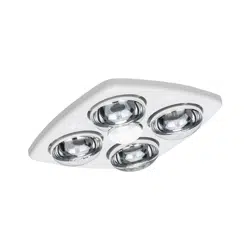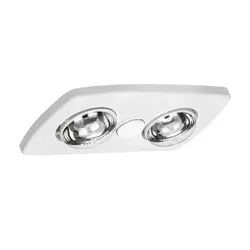
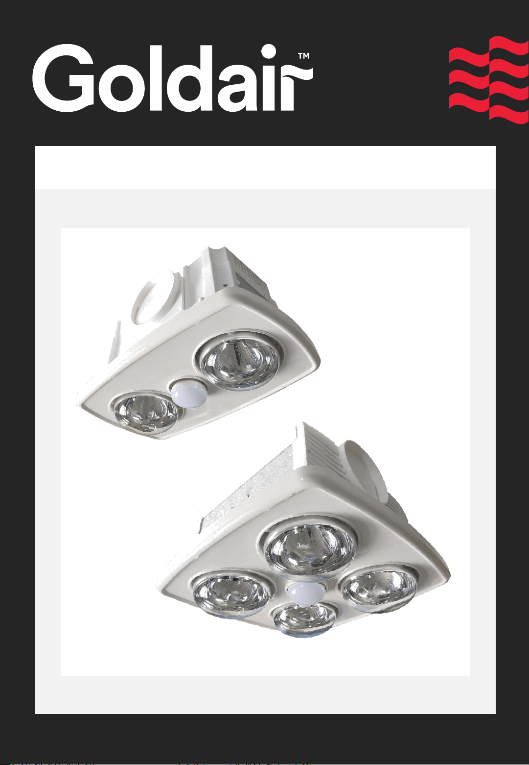
For Models: GHL255W, GHL455W
Classic Heat/Light/Vent
Operating Instructions

Thank you for choosing GOLDAIR. Your GOLDAIR Bathroom Heat/Light/Vent has been
designed and manufactured to high standards of engineering. With proper use and care,
as described in this leaflet, you can expect years of service.
Please read these instructions carefully.
• Keep instructions for future reference.
• Use only the voltage specified on the rating plate of the appliance.
• The heater must not be located immediately below a socket outlet.
• Do not cover or restrict airflow as the appliance may overheat and become a fire risk.
• Do not cover heat lamps, or inlet of airflow by placing these areas of the appliance
against any surface.
• Do not mount appliance close to any heat source.
• Do not operate in areas where petrol, paint or other flammable liquids are used or
stored.
• Do not use the appliance to dry clothes.
• Do not insert or allow foreign objects to enter any point of the appliance, as this may
cause an electric shock, fire or damage to the appliance.
• Do not immerse in liquid or allow liquid to run into the interior of the appliance, as this
could create an electrical shock hazard.
• Do not operate after the appliance malfunctions, has been dropped/damaged in any
manner.
• Do not operate the appliance with wet hands.
• Use this appliance only as described in this manual. Any other use is not recommended
by the manufacturer may cause fire, electric shock or injury.
• Do not use this appliance in a window as rain may cause electric shock.
• Do not connect the appliance to the electrical supply until completely assembled.
• This appliance is intended for household use only and not for commercial or industrial
use.
• This appliance is not intended for use by persons (including children) with reduced
physical, sensory or mental capabilities, or lack of experience or knowledge, unless
they have been given supervision or instruction concerning use of the appliance by a
person responsible for their safety.
• Young children should be supervised to ensure they do not play with the appliance.
• Fixed heaters likely to be used in a bathroom are to be installed so that switches and
other controls cannot be touched by a person in the bath or shower
General Care and Safety Guide
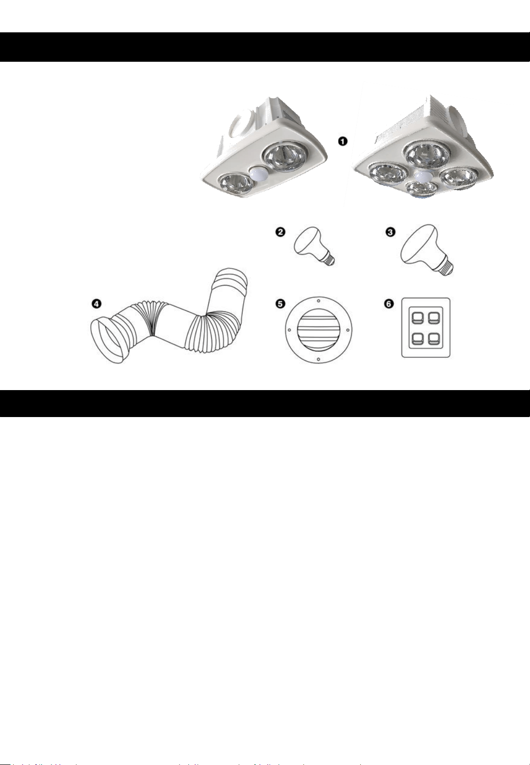
Components
1. Heat Light Vent Unit
2. 9W R63 LED Globe
3. 275W Heat Lamps
4. 3m Ducting
5. Exterior Vent
6. Switch Plate
General Notes
This Goldair product is designed only to be used as a fixed Heat/Light/Vent product,
installed into the ceiling. If the product is installed or used for any other purpose the
warranty will be void.
• Installation of this product must be completed by a registered electrician.
• Handle product with care, remove the bulbs during installation.
• The unit must be located and installed in accordance with the latest edition of
AS/NZS 3000 and any local regulation information for mounting in damp areas
(please consult your local electrician for information).
• The unit can be installed in any room that requires direct radiant heating and
circulated air flow such as bathrooms, ensuites, laundries, etc.
• The unit must be installed in flat ceilings with a minimum height of 2.1 metres from
the floor.
• Do not install the unit directly above shower or bath recesses or enclosures.
• Joints, beams and rafters must not be notched to install the appliance.
• The unit must not be installed in a position where water may splash onto the heat
lamps.
• The appliance shall, under no circumstances, be covered with insulating material or
similar material.
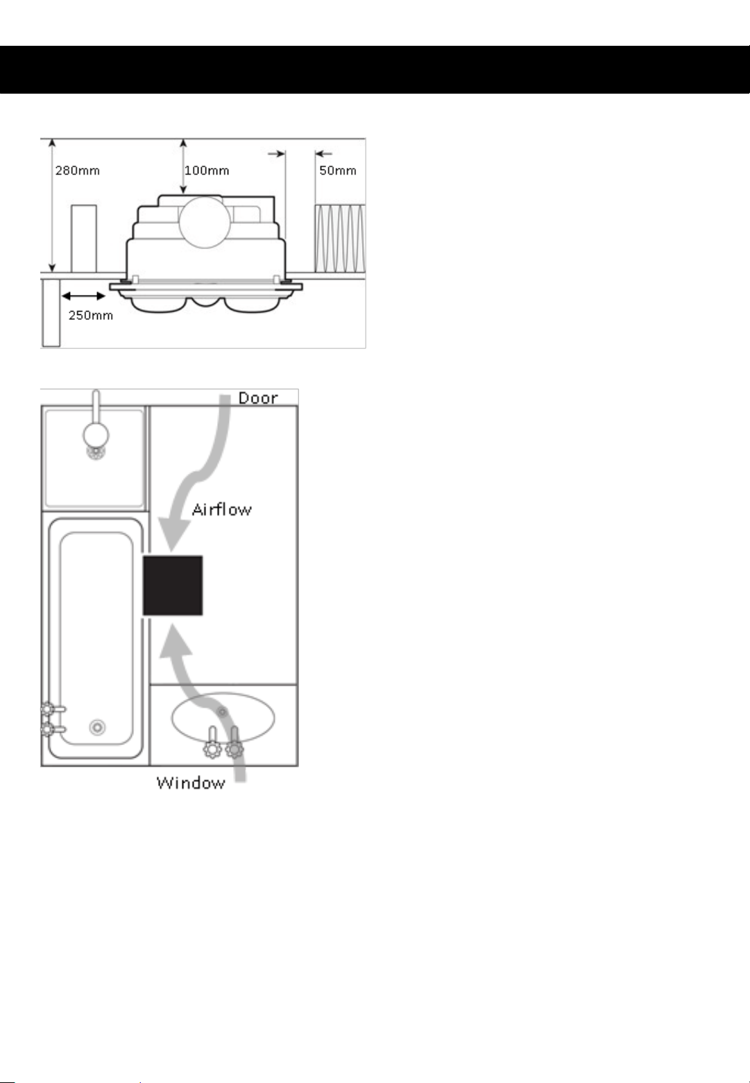
Clearance Requirements
• This unit must be mounted at least
250mm away from vertical walls.
• A minimum clearance of 100mm is
required above the top of the unit.
• A minimum of 50mm clearance is
required between the sides of unit and
joists, walls or insulation.
Ventilation Requirements
• For the exhaust fan to work efficiently,
replacement air of a volume equivalent to
what is being extracted must be able to
enter the room.
• Generally, air would be drawn under the
door, or through a slightly open window.
If the room is airtight, the fan will operate
poorly. Air flow path should ideally pass
over the steam source.
Heat lamps and light bulbs supplied with the
unit are test bulbs only, these are not
covered under the product warranty
General Notes

1. The unit may be mounted either between joists using the inbuilt clip fasteners or
against a joist using a screw through the flange plate.
2. The approximate cut-out size of the 2 Lamp unit is 355 x 200 mm.
3. The approximate cut-out size of the 4 Lamp unit is 310 x 300 mm.
Please note this is only an approximate measurement and any installation would
require a measurement against the physical product to ensure the best fit.
4. Mark the ceiling with a pencil showing the area of ceiling to be cut.
IMPORTANT NOTE: Goldair takes no responsibility for those instances where the physical
product is not measured first before the hole is cut in the ceiling.
5. Before commencing cutting ensure that the area behind the intended location is
clear of all cables, pipes and joists. Once clear, cut out the section along the
previously marked lines.
6. Remove the lamps from the housing by unscrewing them anticlockwise. Then
remove the decorative fascia from the housing by removing the spring clips that hold
it in place.
7. Insert the unit into the hole being sure to pull the side springs inward so that the
body can pass through the hole without damaging the plaster. Ensure that the unit is
held securely in place by clips. It is essential that additional screws (not supplied) are
used to aid holding the unit in the ceiling. Screw holes are provided in the flange for
this purpose. 2 strips of timber (one on each side) should be placed behind the holes
inside the ceiling to give the screws something to anchor to and to provide some
reinforcing. Do not secure the unit at this time.
8. Remove the unit from the ceiling and connect the wiring to the terminal block as per
the wiring diagram. This terminal block is on one corner of the back of the unit.
9. Attach ducting to extract the air to the outer wall using flexible ducting, clamps and
vent outlet grille provided. Fix and tighten the clamps firmly to hold the flexible duct
to the unit and the outer wall vent.
10.Insert the unit into the hole and secure as detailed in point 4 above.
11.Hold the fascia against the body of the appliance and the ceiling, then attach the
securing spring clips to hold the fascia in place.
12.Now screw in the heat lamps provided into the lamp holder through the holes
provided in the fascia. The globes should be screwed in firmly to ensure a good
electrical contact but don’t over tighten. Fit the small centre light bulb in the same
way ensuring that it is positioned centrally.
13.IMPORTANT NOTE: Over tightening of heat lamps or light bulbs may result in
damages to the lamp holders or lamps, take care when removing and replacing heat
lamps/bulbs.
Installation Instructions
IMPORTANT NOTE: All electrical work and installation of this product must be performed
by a Registered Electrician in accordance with the latest edition of AS/NZS 3000.
We do not recommend additional exhaust fans to be connected into the system as noted
in some home installations.
If this is cannot be avoided, the installation must be performed by a Registered
Electrician.
Ensure power to the circuit to be used has been isolated at the power board before
carrying out any electrical work.
TECHNICAL SPECIFICATIONS
GHL255W
220-240VAC 50-60Hz
594W (Max)
GHL455W
220-240VAC 50-60Hz
1144W (Max)
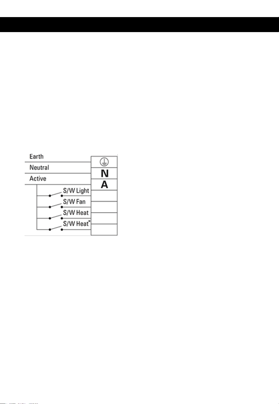
WIRING DIAGRAM
* Second heat switch not required
for model with 2 heat lamps
The unit requires ‘permanent active’. The
fitting is fitted with a thermal cut-out which
will turn the motor (FAN) ‘ON’ when the
internal temperature exceeds 80˚C.
1. Double pole disconnecting device must be
fitted in thecircuit.
2. Ensure the power is switched
“OFF” at the mains before
commencing installation.
3. Remove the cover on the back of the
enclosure to access the terminals.
4. Connect wires as per electrical wiring
diagram and markings adjacent to
terminalblock.
5. Replace the cover removedearlier.
(Green)
(Blue)
(Red)
Electrical Installation
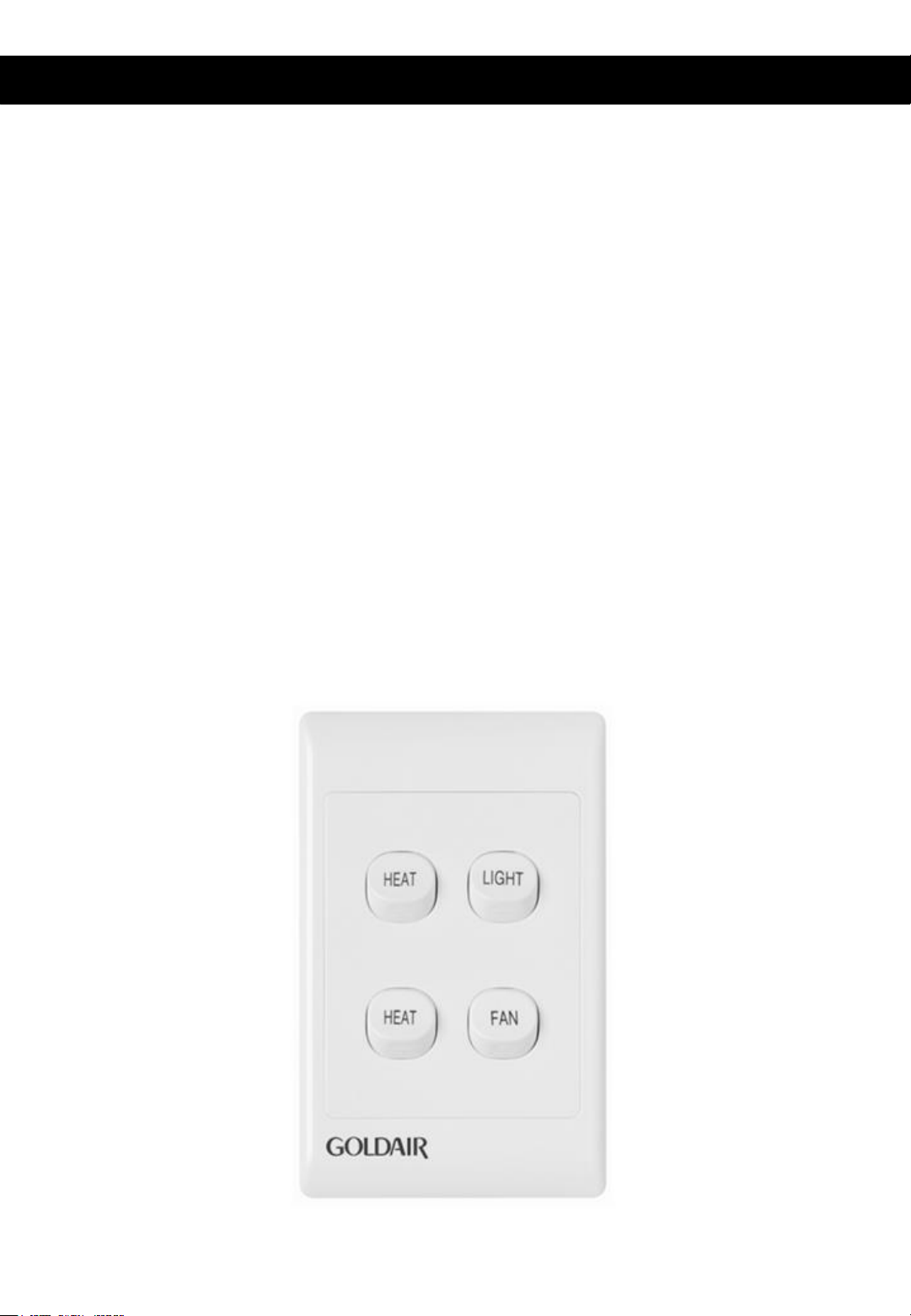
Your Heat/Light/Fan unit comes with a wall switch included. Once wired correctly by your
electrician you need to simply follow the below instructions.
• To turn the centre light bulb on press the “LIGHT” switch down (and up to turn off).
• To turn the ventilation fan on press the “FAN” switch down (and up to turn off).
• To turn 2 heat lamps on press one of the “HEAT” switches down (and up to turn off).
• To turn all 4 heat lamps on press both of the “HEAT” switches down (and up to turn off).
Air Flow Requirements:
For maximum efficiency to remove steam and odours, there must be an adequate air flow
within the room. To obtain maximum air flow ensure there is a gap under doors or open
windows slightly. A good test for this is that the fan should not change speed (or sound)
when you close or open the bathroom door.
Important Note:
Always turn the fan on when using the heat lamps to minimise any undue heat build up
in the unit.
User Instructions

Cleaning
• Switch off the power before commencing cleaning
• Wait until the globes cool down.
• Regularly wipe globes and front fascia with soft cloth soaked with water or neutral
detergent if required.
• Clean the exhaust fan from dust and dirt with dry or wet cloth if required.
• Clean the exhaust ducting kit and ensure airways are clean and there are no
obstructions at the exit from the wall.
Goldair – New Zealand
Monday – Friday 8am-5pm
Phone +64 (0)9 917 4000
Phone 0800 232 633
Goldair – Australia
Monday – Friday 8am-5pm
Phone +61 (0)3 9336 4423
Phone 1300 465 324
[email protected]om.au
SUPPORT AND TECHNICAL ADVICE
PROOF OF PURCHASE
To receive warranty, retain receipt as proof of purchase.
Thank you for purchasing this Goldair product. Your product is warranted against faults and manufacture when
used in normal domestic use for a period of one year. In non-domestic use Goldair limits the voluntary warranty to
three months.
Goldair undertake to repair or replace this product at no charge if found to be defective due to a manufacturing
fault during the warranty period.
This warranty excludes damage caused by misuse, neglect, shipping accident, incorrect installation, or work carried
out by anyone other than a qualified electrical service technician.
PLEASE KEEP YOUR RECEIPT AS THIS WILL HELP VERIFY YOUR WARRANTY.
The benefits given to you by this warranty are in addition to other rights and remedies available to you under law in
relation to the goods or services to which this warranty relates.
In Australia, our goods come with guarantees that cannot be excluded under the Australian Consumer Law. You are
entitled to a replacement or refund for a major failure and compensation for any other reasonably foreseeable loss
or damage. You are also entitled to have the goods repaired or replaced if the goods fail to be of acceptable quality
and the failure does not amount to a major failure.
In New Zealand this warranty is additional to the conditions and guarantees of the Consumers Guarantee Act
(1993).
One Year Warranty
Goldair Two Year Warranty (IMPORTANT: Please complete and retain this warranty card)
Name
Address
Place Of Purchase Date Of Purchase
Name Of Product Model Number
Attach a copy of the purchase receipt to this warranty card
Due to continual design improvements, the product illustrated in this User Manual may differ slightly from the actual product.
Goldair – New Zealand
CDB Goldair
PO Box 100-707
N.S.M.C
Auckland
Phone +64 (0)9 917 4000
Phone 0800 232 633
www.goldair.co.nz
Goldair – Australia
CDB Goldair Australia Pty
PO Box 574
South Morang
Victoria, 3752
Phone +61 (0)3 9365 5100
Phone 1300 GOLDAIR (1300 465 324)
www.goldair.com.au

New Zealand
PO Box 100707,
North Shore Mail Centre,
Auckland, 0745
www.goldair.co.nz
Australia
PO Box 574,
South Morang,
Victoria, 3752
www.goldair.com.au