Loading ...
Celestron, 2835 Columbia Street, Torrance, CA 90503 • Phone (310) 328-9560 • Fax (310) 212-5835 #93514-INST 01-08
speed rate regulator clockwise to increase the motor speed. If, however, the star is drifting East, then the motors are tracking too
fast. Turn the speed rate regulator counterclockwise to decrease the motor speed. Repeat this process until the star remains
centered in the eyepiece for several minutes. Remember to ignore any star drift in declination.
The Motor Drive is also equipped with a North/South switch that can reverse the direction of the motor for Southern Hemisphere
use. Simply slide the switch to "N" when operating in the Northern Hemisphere and "S" when operating in the Southern
Hemisphere.
Installing the Motor Drive to the Mount
The Logic Drive motor attaches to the CG-3 EQ mount via a flexible coupler that mounts to the right ascension (R.A.) slow
motion shaft and a motor bracket that holds the motor in place. The motor drive comes two brackets; one for the CG-2 mount and
one for the CG-3.
To install the mounting bracket:
1. Remove the two mounting screws from the front of the
motor cover. See Fig 1
2. Remove the motor cover from the motor.
3. Remove the nuts and screws that hold the bracket to the
motor housing.
4. Use the same nuts and screws to attach the desired
bracket (for the CG-2 or CG-3 mount) as shown in Figure
2.
5. Replace the mount cover.
To install the motor drive:
1. Remove the slow motion cable from the R.A. slow motion
shaft.
2. Remove the 3/8" long Allen head screw located on the side
of the polar shaft. For the CG-2 mount it is located
opposite of the latitude scale. For the CG-3 mount it is
located on the side of the polar housing. See figure 2 & 3.
3. Align the slotted hole on the mounting bracket with the
hole on the side of the mount.
4. Place the Allen head screw through the motor bracket and
thread it into the hole on the side of the mount. Tighten the
screw with an Allen wrench.
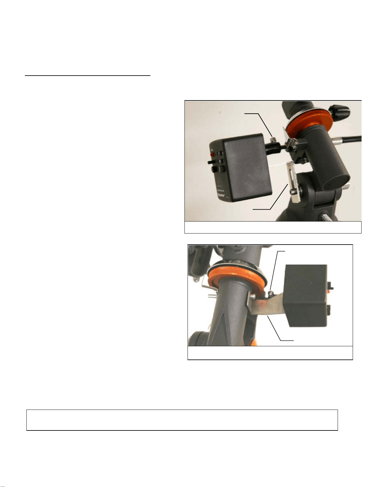
5. Slide the open end of the flexible motor coupler over the
R.A. shaft. Make sure that the screw on the flexible motor
coupler is positioned over the flat portion of the R.A. shaft.
Use the large spur gear on the opposite side of the R.A. worm shaft to rotate the R.A. shaft until the flat portion is aligned
with the screw on the motor coupling.
6. Tighten the motor coupler screw with a flathead screwdriver.
Warranty: One year limited warranty. See the Celestron Accessory Catalog (#93685) for complete warranty details or contact Celestron
Celestron International, 2835 Columbia Street, Torrance, CA 90503 • Phone (310) 328-9560 • Fax (310) 212-5835
Motor Bracke
t
Flexible Moto
r
Couple
r
Fig 2 – Motor drive shown on CG-2 Mount
Fig 3 – Motor drive shown on CG-3 Mount
Motor Bracket
Flexible Motor
Coupler