Loading ...
Loading ...
Loading ...
4
Final Tubing Check
IMPORTANT: Check to be certain factory tubing on both indoor
and outdoor unit has not shifted during shipment. Ensure tubes are
not rubbing against each other or any sheet metal or wires. Pay
close attention to feeder tubes, making sure wire ties on feeder
tubes are secure and tight.
Installing with Indoor Piston
Outdoor Unit Connected to Factory Approved Indoor Unit
Check piston size shipped with indoor unit to see if it matches
required indoor piston size. If it does not match, replace indoor
piston with correct piston size.
NOTE: Correct pistons are shipped with select outdoor units in
the accessory bag and are only for use in certain qualified and
approved fan coils, i.e. FB4C. (See Product Data for list of
approved fan coils that use accessory piston.)
The piston included with the FFMANP* and FPMAN* fan coils
are unique to those products and CANNOT be replaced with the
piston shipped with outdoor unit. Refer to the AHRI Directory to
check if a certain combination can use a piston or requires an
accessory TXV.
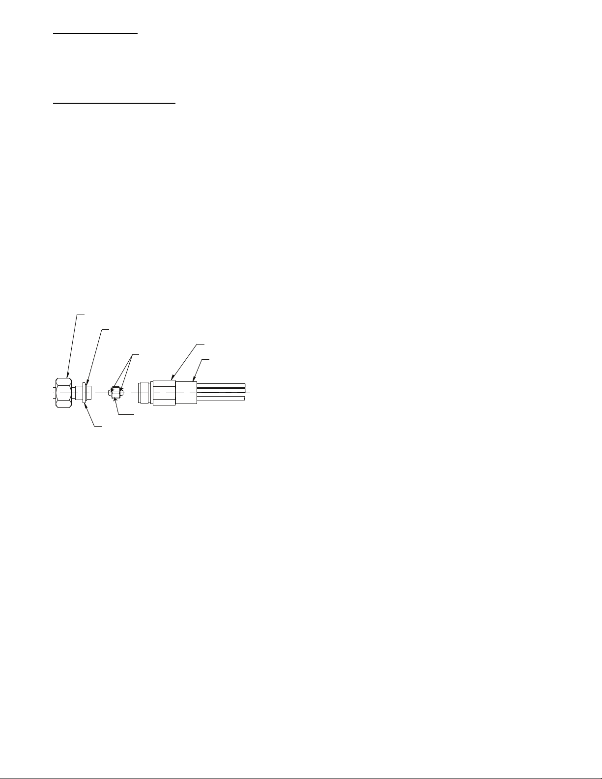
When changing indoor piston, use a back−up wrench. Hand
tighten hex nut, then tighten with wrench 1/2 turn. Do not exceed
30 ft−lbs. The indoor piston contains a Teflon ring (or seal) which
is used to seat against the inside of distributor body, and must be
installed properly to ensure proper seating. See Fig. 5.
13/16” BRASS HEX NUT
TEFLON® SEAL
TEFLON®
RINGS
3/4” BRASS HEX BOD
Y
“H” DISTRIBUTOR
PISTON RETAINER
PISTON
A10342
Fig. 5 -- Indoor (Cooling) Piston
Units with Cooling Mode TXV
Units installed with cooling mode TXV require charging by the
subcooling method.
1. Operate unit a minimum of 15 minutes before checking
charge.
2. Measure liquid service valve pressure by attaching an accur-
ate gage to service port.
3. Measure liquid line temperature by attaching an accurate
thermistor type or electronic thermometer to liquid line near
outdoor coil.
4. Refer to unit rating plate for required subcooling temperat-
ure.
5. Refer to Table 2 -- Rating Plate (required) Subcooling Tem-
perature. Find the point where required subcooling temper-
ature intersects measured liquid service valve pressure.
6. To obtain required subcooling temperature at a specific li-
quid line pressure, add refrigerant if liquid line temperature
is higher than indicated or reclaim refrigerant if temperature
is lower. Allow a tolerance of 3_F(1.7_C).
Units with Indoor Piston
Units installed with indoor pistons require charging by the
superheat method.
The following procedure is valid when indoor airflow is within
21 percent of its rated CFM.
1. Operate unit a minimum of 15 minutes before checking
charge.
2. Measure suction pressure by attaching an accurate gage to
suction valve service port.
3. Measure suction temperature by attaching an accurate ther-
mistor type or electronic thermometer to suction line at ser-
vice valve.
4. Measure outdoor air dry--bulb temperature with thermomet-
er.
5. Measure indoor air (entering indoor coil) wet--bulb temper-
ature with a sling psychrometer.
6. Refer to Table 3 -- Superheat Charging -- AC Only.Find
outdoor temperature and evaporator entering air wet--bulb
temperature. At this intersection, note superheat. Where a
dash (----) appears on the table, do not attempt to charge sys-
tem under these conditions or refrigerant slugging may oc-
cur. Charge must be weighted in, adding or removing 0.6
oz/ft of 3/8 liquid line above or below 15 feet (4.6m) re-
spectively.
7. Refer to Table 4 -- Required Suction--Line Temperature.
Find superheat temperature (from #6 above) and suction
pressure. At this intersection, note suction line temperature.
8. If unit has a higher suction line temperature than charted
temperature, add refrigerant until charted temperature is
reached.
9. If unit has a lower suction line temperature than charted
temperature, reclaim refrigerant until charted temperature is
reached.
10. When adding refrigerant, charge in liquid form into suction
service port using a flow--restricting device.
11. If outdoor air temperature or pressure at suction valve
changes, charge to new suction line temperature indicated
on chart.
12. Optimum performance will be achieved when the operating
charge produces 10_F suction superheat at suction service
valve with 95_F(35_C) outdoor ambient and 80_F(27_C)
dry bulb (67_F/19_C) wet bulb) indoor temperature (DOE
“A” test conditions) at rated airflow.
Loading ...
Loading ...
Loading ...