Loading ...

2
7. OPERATING INSTRUCTIONS
7-1 Attention before operation
7-1-1 Check 7V battery. If the battery voltage is less than 7V, display will
show “ ”, the battery should be replaced at this time to ensure
measuring precision.
7-1-2 Pay attention to the “ ” besides the input jack which shows that
the input voltage or current should be within the specified value.
7-1-3 The range switch should be positioned to desired range for
measurement before operation.
7-2 Measuring DC Voltage
7-2-1 Connect the black test lead to COM jack and the red to VΩmA jack.
7-2-2 Set the rotary switch at the desired V range position.
7-2-3 Connect test leads across the source or load under
measurement.
7-2-4 You can get reading from LCD. The polarity of the red lead
connection will be indicated along with the voltage value.
NOTE:
1. When the value scale to be measured is unknown beforehand, set the
range selector at the highest position.
2. When only the figure’1’ or ‘-1’ is displayed, it indicates over-range
situation and the higher range has to be selected.
3. “ ” means you can’t input the voltage more than 600V, it’s possible
to show higher voltage, but it may destroy the inner circuit or pose a
shock.
4. Be cautious against shock when measuring high Voltage.
7-3 Measuring AC Voltage
7-3-1 Connect the black test lead to COM jack and the red to VΩmA jack.
7-3-2 Set the rotary switch at the desired V~ range position.
7-3-3 Connect test leads across the source or load under
measurement.
7-3-4 You can get reading from LCD.
NOTE:
1. When the value scale to be measured is unknown beforehand, set the
range selector at the highest position.
2. When only the figure’1’ or ‘-1’ is displayed, it indicates over-range
situation and the higher range has to be selected.
3. “ ” means you can’t input the voltage more than 600V, it’s possible
to show higher voltage, but it may destroy the inner circuit or pose a
shock.
4. Be cautious against shock when measuring high Voltage.
7-4 Measuring DC Current
7-4-1 Connect the black test lead to COM jack and the red to the VΩmA
jack for a maximum 200mA current , for a maximum 10A current,
move the red lead to the 10A jack.
7-4-2 Set the rotary switch at the desired A range position.
7-4-3 Connect test leads in series with the load under measurement.
7-4-4 You can get reading from LCD. The polarity of the red lead
connection will be indicated along with the current value.
NOTE:
1. When the value scale to be measured is unknown beforehand, set
the range selector at the highest position.
2. When only the figure’1’ or ‘-1’ is displayed, it indicates over-range
situation and the higher range has to be selected.
3. “ ” means the socket mA’s maximum current is 200mA and 10A’s
maximum current is 10A, over current will destroy the fuse. Since
10A is not fused, the measuring time should be less than 1 second to
prevent precision from affecting by circuit heating.
7-5 Measuring Resistance
7-5-1 Connect the black test lead to COM jack and the red to VΩmA jack.
7-5-2 Set the rotary switch at the desired Ωrange position.
7-5-3 Connect test leads across the resistance under
measurement.
7-5-4 You can get reading from LCD.
NOTE:
1. When only the figure’1’ or ‘-1’ is displayed, it indicates over-range
situation and the higher range has to be selected.
2. For measuring resistance above 1M Ω , the mete may take a few
seconds to get stable reading.
3. When the input is not connected, i.e. at open circuit, the figure ‘1’ will
be displayed for the over-range condition.
4. When checking in-circuit resistance, be sure the circuit under test
has all power removed and that all capacitors have been discharged
fully.
5. the value scale to be measured is unknown beforehand, set the
range selector at the highest position.
7-6 Measuring Temperature
7-6-1 Set the rotary switch at the ℃ range position.
7-6-2 The LCD will sow the current temperature of the environment.
7-6-3 When measuring temperature with thermocouple, temperature probe
for this meter can be used. Insert ‘K’ type thermocouple probe (red
one into VΩmA jack and black one into COM jack)
7-6-4 You can get a reading from LCD.
7-6-5 In order to guarantee the accuracy of the measurement , need
to close Light switch while measuring temperature.;
7-7 Transistor Testing
7-7-1 Set the rotary switch at ’hFE’ position.
7-7-2 Determine whether the transistor under testing is NPN or PNP and
locate the emitter, base and collector leads. Insert the leads into
proper holes of hFE socket on the front panel.
7-7-3 Read the approximate hFE value at the testing condition of base
current Ib10uA and Vce 3V.
7-8 Diode Testing
7-8-1 Connect the black test lead to COM jack and the red to VΩmA jack.
(the polarity of red lead is ‘+’)
7-8-2 Set the rotary switch at the F range position.
7-8-3 Connect the red lead to the anode and the black lead to
the cathode of the diode under testing.
7-8-4 You can get a reading from LCD.
NOTE:
1. The meter will show approximate forward voltage drop of the diode.
2. If the lead connections is reversed, only ‘1’ will be displayed.
7-9 Continuity Testing
7-9-1 Connect the black test lead to COM jack and the red to VΩmA jack.
7-9-2 Set the rotary switch at the range position.
7-9-3 Connect test leads across two points of the circuit
under testing.
7-9-4 If continuity exists (i.e. resistance less than about 90Ω ), built-in
buzzer will sound.
NOTE:
If the input open circuit, the figure ‘1’ will be displayed.
8. Maintenance
8-1 Before attempting to remove the battery door or open the case, be
sure that test leads have been disconnected from measurement circuit
top avoid electric shock hazard.
8-2 To avoid electrical shock, remove test leads from measurement circuits
before replacing the fuse. For protection against fire, replace fuses only
with specified ratings: F-200mA/250V fuse.
8-3 Your must replace the test leads if the lead is exposed, and should
adopt the leads with the same specifications as origin.
8-4 Use only moist fabric or small amount of detergent but not chemical
solution for cleaning.
8-5 do not use the meter before the back cover is properly closed and
screw secured. Upon any abnormality, stop operation immediately
and send the meter for maintenance.
8-6 Please take out the battery when not using for a long time.
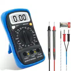
9. Accessories
[1] Test Leads: electric rating 1000V 10A
[2] Fuse: F-200mA/250V
[3] ‘K’ type Thermocouple
[4] Operator’s Manual
Above picture and content just for your reference. Please
be subject to actual products if anything diffferent or
updated. Please pardon for not informing in advance.