
Projector
PA1004UL-W/PA1004UL-B
PA804UL-W/PA804UL-B
User’s Manual
Model No.
NP-PA1004UL-W/NP-PA1004UL-B/NP-PA804UL-W/NP-PA804UL-B
For USA

i
Introduction .............................................................................................................................................. iv
Important Information ........................................................................................................................ v
1. Check the product overview, supplied items and part names .................................... 1
1-1. Introduction to the Projector ............................................................................................................ 1
1-2. What’s in the Box? ................................................................................................................................. 4
1-3. Part Names of the Projector .............................................................................................................. 6
1-4. Part Names of the Remote Control .............................................................................................. 10
2. Projecting an Image (Basic Operation) ................................................................................. 16
2-1. Flow of Projecting an Image .......................................................................................................... 16
2-2. Connecting Your Computer/Connecting the Power Cord .................................................. 17
2-3. Turning on the Projector ................................................................................................................. 20
2-4. Selecting a Source ............................................................................................................................. 23
2-5. Adjusting the Picture Size and Position ..................................................................................... 26
2-6. Adjusting a picture and sound ...................................................................................................... 36
2-7. Turning off the Projector ................................................................................................................. 37
2-8. After Use ................................................................................................................................................ 38
3. Convenient Features ....................................................................................................................... 39
3-1. Turn off the light of the projector (LENS SHUTTER) ............................................................... 39
3-2. Turning Off the On-Screen Menu (On-Screen Mute) ............................................................. 39
3-3. Enlarging a Picture ............................................................................................................................. 40
3-4. Adjustment of luminance (brightness) and energy-saving effect ................................... 41
3-5. Correcting Horizontal and Vertical Keystone Distortion [CORNERSTONE] .................... 45
3-6. Operation for the On-Screen Menu by a commercially available USB mouse ............. 48
3-7. Preventing the Unauthorized Use of the Projector [SECURITY] ........................................ 50
3-8. Projecting 3D videos ......................................................................................................................... 53
3-9. Controlling the Projector by Using an HTTP Browser ........................................................... 56
3-10. Storing Changes for Lens Shift, Zoom, and Focus [LENS MEMORY] ............................. 59
Table of Contents

ii
Table of Contents
4. Multi-Screen Projection ................................................................................................................ 66
4-1. Things that can be done using multi-screen projection ...................................................... 66
4-2. Using a single projector to project two types of videos at the same time [PIP/
PICTURE BY PICTURE] .......................................................................................................................... 67
4-3. Line up multiple projectors to display a high resolution image in a larger
screen [TILING] ....................................................................................................................................... 71
4-4. Adjust boundaries of a projected image [EDGE BLENDING] .............................................. 74
5. Using On-Screen Menu ................................................................................................................... 82
5-1. Using the Menus ................................................................................................................................ 82
5-2. Menu Elements ................................................................................................................................... 83
5-3. List of Menu Items ............................................................................................................................. 84
5-4. Menu Descriptions & Functions [INPUT] ................................................................................... 92
5-5. Menu Descriptions & Functions [ADJUST] ................................................................................ 96
5-6. Menu Descriptions & Functions [DISPLAY] ............................................................................. 111
5-7. Menu Descriptions & Functions [SETUP] ................................................................................. 123
5-8. Menu Descriptions & Functions [INFO.] ................................................................................... 156
6. Connecting to Other Equipment ............................................................................................ 159
6-1. Connecting Your Computer ......................................................................................................... 160
6-2. Connecting to a DVD player and other AV devices ............................................................. 164
6-3. Connecting to a HDBaseT transmission device (sold commercially) ............................ 166
6-4. Connecting several projectors .................................................................................................... 167
6-5. Connecting to a Wired LAN .......................................................................................................... 168
7. Maintenance .................................................................................................................................... 169
7-1. Cleaning the Lens ............................................................................................................................ 169
7-2. Cleaning the Cabinet ...................................................................................................................... 170

iii
Table of Contents
8. Appendix ............................................................................................................................................ 171
8-1. Throw distance and screen size .................................................................................................. 171
8-2. Compatible Input Signal List ........................................................................................................ 177
8-3. Specifications .................................................................................................................................... 182
8-4. Cabinet Dimensions ........................................................................................................................ 186
8-5. Pin assignments and signal names of main connectors .................................................... 187
8-6. Changing the Background Logo (Virtual Remote Tool) ..................................................... 190
8-7. Troubleshooting ............................................................................................................................... 191
8-8. PC Control Codes and Cable Connection ................................................................................ 197
8-9. About the ASCII Control Command .......................................................................................... 199
8-10. List of Art-Net DMX parameters ............................................................................................... 201
8-11. Mounting a lens (separately sold) ........................................................................................... 203
8-12. Attaching the option cover (separately sold) ...................................................................... 207
8-13. Portrait projection (vertical orientation) .............................................................................. 210
8-14. For multi-Screen projection ....................................................................................................... 212
8-15. Troubleshooting Check List ....................................................................................................... 213
8-16. REGISTER YOUR PROJECTOR! (for residents in the United States, Canada, and
Mexico) ................................................................................................................................................... 215

iv
Thank you for purchasing the NEC projector.
This projector can be connected to computers, video devices, etc. to project images sharply onto
a screen.
Please read this manual carefully before using your projector and keep the manual handy for future
reference.
Read this user’s manual if you have any doubts about operation or if you believe the projector may
be faulty.
Ver. 1 5/20
NOTES
(1) The contents of this user’s manual may not be reprinted in part or whole without permission.
(2) The contents of this user’s manual are subject to change without notice.
(3) Great care has been taken in the preparation of this user’s manual; however, should you notice
any questionable points, errors or omissions, please contact us.
(4) Notwithstanding article (3), NEC will not be responsible for any claims on loss of profit or other
matters deemed to result from using the Projector.
Introduction
v
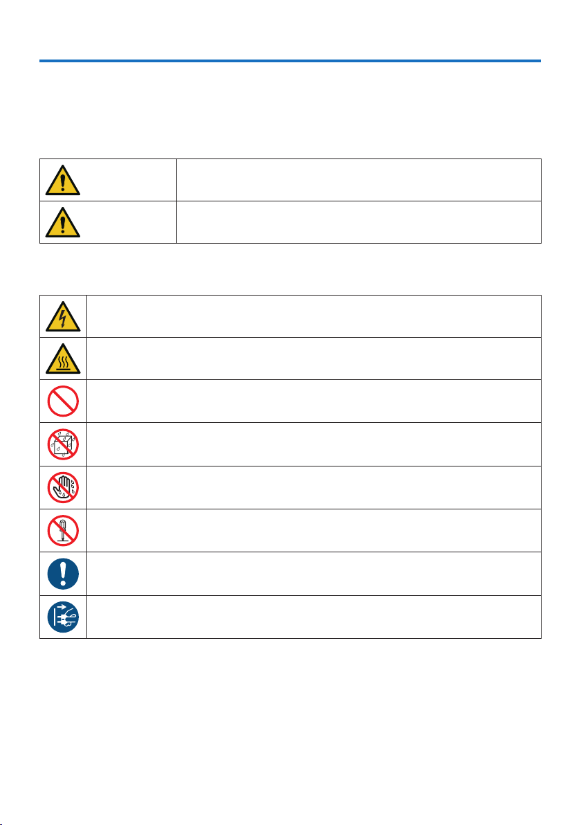
About the symbols
To ensure safe and proper use of the product, this manual uses a number of symbols to prevent
injury to you and others as well as damage to property.
The symbols and their meanings are described below. Be sure to understand them thoroughly
before reading this manual.
WARNING
Failing to heed this symbol and handling the product erroneously
could result in accidents leading to death or major injury.
CAUTION
Failing to heed this symbol and handling the product erroneously
could result in personal injury or damage to surrounding property.
Examples of symbols
This symbol indicates you should be careful of electric shocks.
This symbol indicates you should be careful of high temperatures.
This symbol indicates something that must be prohibited.
This symbol indicates something that must not be got wet.
This symbol indicates you should not touch with wet hands.
This symbol indicates something that must not be disassembled.
This symbol indicates things you must do.
This symbol indicates that the power cord should be unplugged from the power outlet.
Important Information
Important Information
vi
Safety Cautions
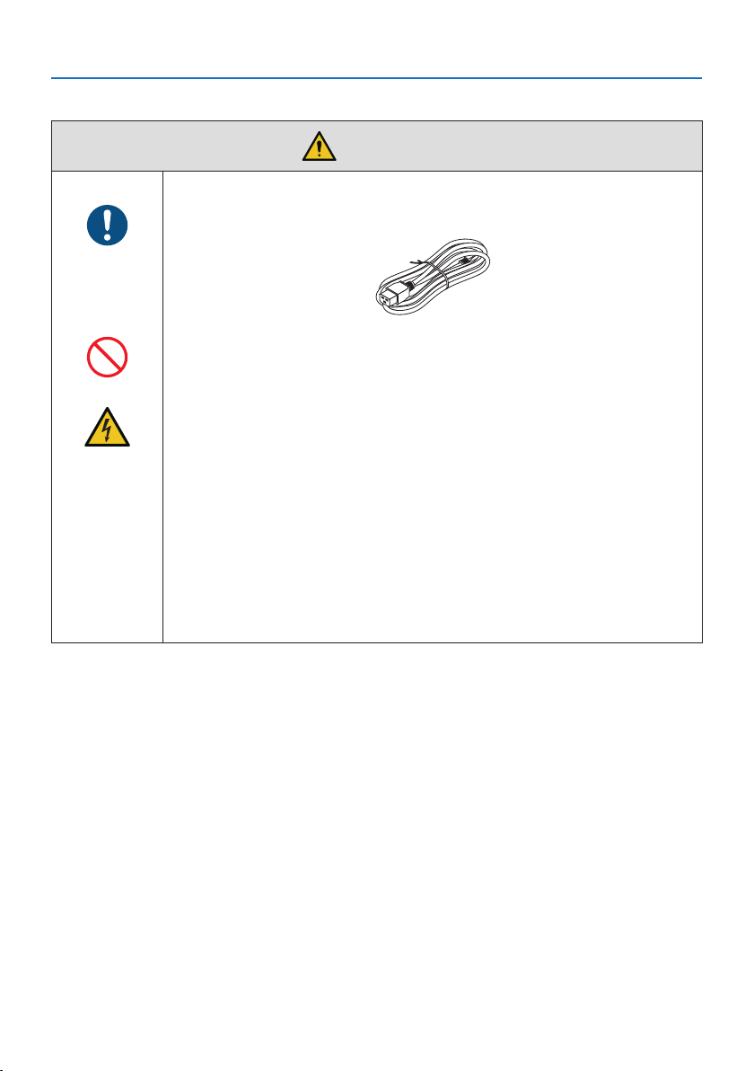
WARNING
Handling the power cord
BE SURE TO DO
•Pleaseusethepowercordsuppliedwiththisprojector.
PROHIBITION
•Thepowercordincludedwiththisprojectorisexclusivelyforusewiththis
projector. For safety, do not use it with other devices.
HAZARDOUS
VOLTAGE
•Handlethepowercordwithcare.Damagingthecordcouldleadtoreor
electric shock.
- Do not place heavy objects on the cord.
- Do not place the cord under the projector.
- Do not cover the cord with a rug, etc.
- Do not scratch or modify the cord.
- Do not bend, twist or pull the cord with excessive force.
- Do not apply heat to the cord.
Should the cord be damaged (exposed core wires, broken wires, etc.), ask
your dealer to replace it.
•Donottouchthepowerplugshouldyouhearthunder.Doingsocouldresult
in electric shock.
Important Information
vii
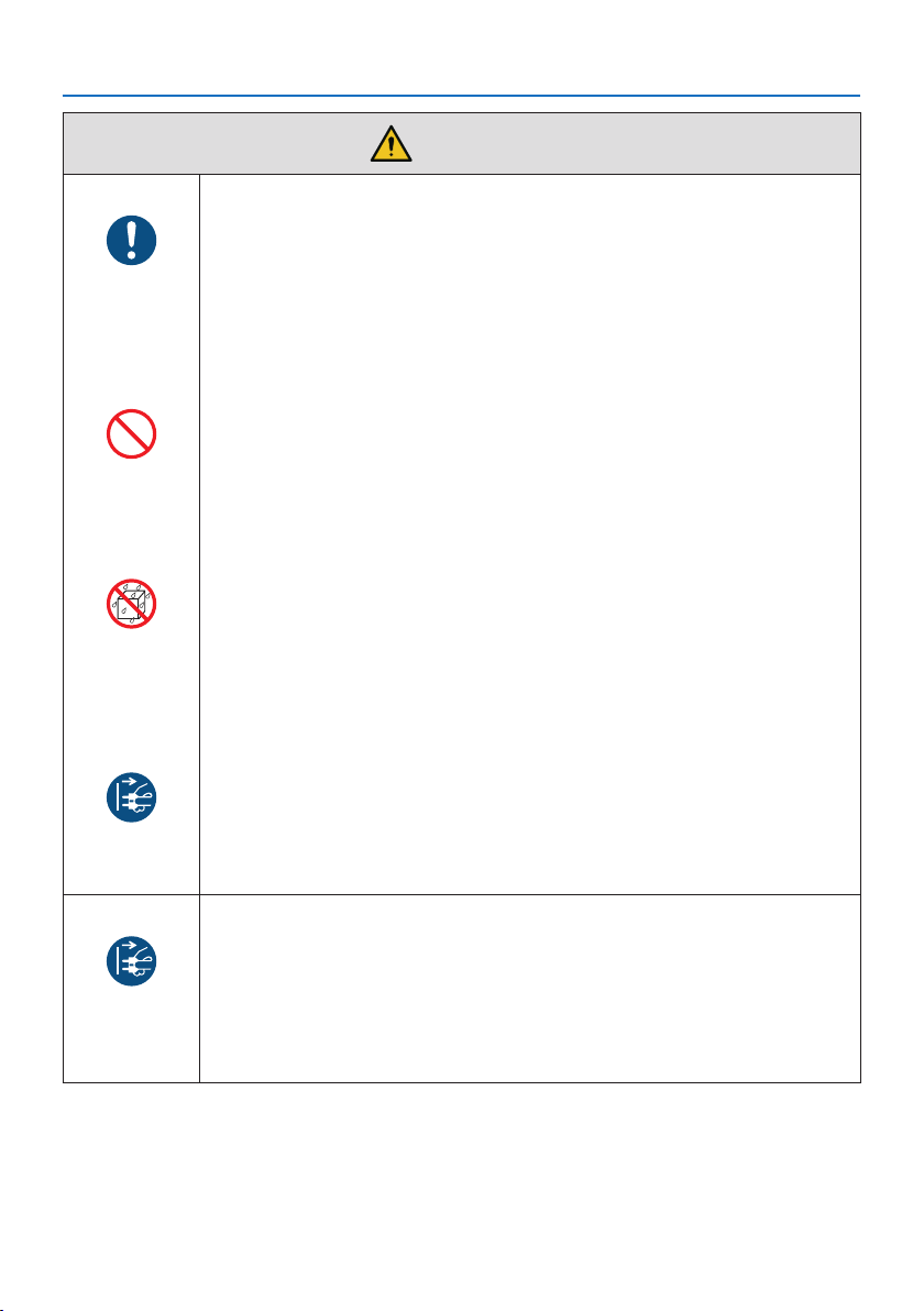
WARNING
Installing the Projector
BE SURE TO DO
•Thisprojectorisdesignedtobeusedwitha100–240VAC,50/60Hzpower
supply. Before using the projector, check that the power supply to which the
projector is to be connected meets these requirements.
•Useapoweroutletastheprojector’spowersupply.Donotconnectthe
projector directly to electrical light wiring. Doing so is dangerous.
•Wheninstallingtheprojectoratanangle,theseparatelysoldoptioncover
may be required for safety depending on the installation angle of the projec-
tor. (→ page
xix)
PROHIBITION
•Donotuseinplacessuchasthosedescribedbelow.Doingsocouldleadto
fire or electric shock.
- Shaky tables, inclined surfaces or other unstable places
- Near heating appliances or places with heavy vibrations
- Outdoors or humid or dusty places
- Places exposed to oil smoke or steam
- Near cooking appliances, humidifiers, etc.
DO NOT WET
•Donotuseinplacessuchasthosedescribedbelowwheretheprojectorcould
get wet. Doing so could lead to fire or electric shock.
- Do not use in the rain or snow, on a seashore or waterfront, etc.
- Do not use in a bathroom or shower room.
- Do not place vases or potted plants on the projector.
- Do not place cups, cosmetics or medicines on the projector.
Should water, etc. get inside the projector, first turn off the projector’s power,
then unplug the power cord from the power outlet and contact your dealer.
UNPLUG THE
POWER CORD
•Donotinsertordropmetalorcombustibleobjectsorotherforeignmaterials
into the projector from the vents. Doing so could lead to fire or electric shock.
Be particularly careful if there are children in the home. Should a foreign object
get inside the projector, first turn off the projector’s power, then unplug the
power cord from the power outlet and contact your dealer.
Unplug the power cord if the projector malfunctions.
UNPLUG THE
POWER CORD
•Shouldtheprojectoremitsmokeorstrangeodorsorsounds,oriftheprojec-
tor has been dropped or the cabinet broken, turn off the projector’s power,
then unplug the power cord from the power outlet. It may cause not only fire
or electric shock but also serious damage to your eyesight or burns. Contact
your dealer for repairs.
Never try to repair the projector on your own. Doing so is dangerous.
Important Information
viii
WARNING
Do not disassemble the projector.
DO NOT
DISASSEMBLE
•Donotremoveoropentheprojector’scabinet.
Also, do not modify the projector. There are high voltage areas in the projec-
tor. It may cause fire, electric shock, or laser light leakage, resulting in serious
damage to your eyesight or burns.
Have qualified service personnel perform inspection, adjustments and repairs
of the interior.
Installing suspended from the ceiling
CAUTION
•Shouldspecialworksberequired,forexampletosuspendtheprojectorfrom
the ceiling, consult your dealer.
Never try to install the projector yourself in such cases. The projector could
drop and cause injury.
Suspending the projector from the ceiling requires sufficient ceiling strength
to support the projector, and the building standards laws in your particular
country must be followed.
It is also necessary to take measures to prevent the projector from dropping
in anticipation of a malfunction occurring in the projector, ceiling mounting
device and installation location.
•Wheninstalledsuspendedfromtheceiling,etc.donothangfromtheprojec-
tor. The projector could drop and cause injury.
•Wheninstallingsuspendedfromtheceiling,useapoweroutletthatiswithin
reach so the power cord can be easily plugged and unplugged.
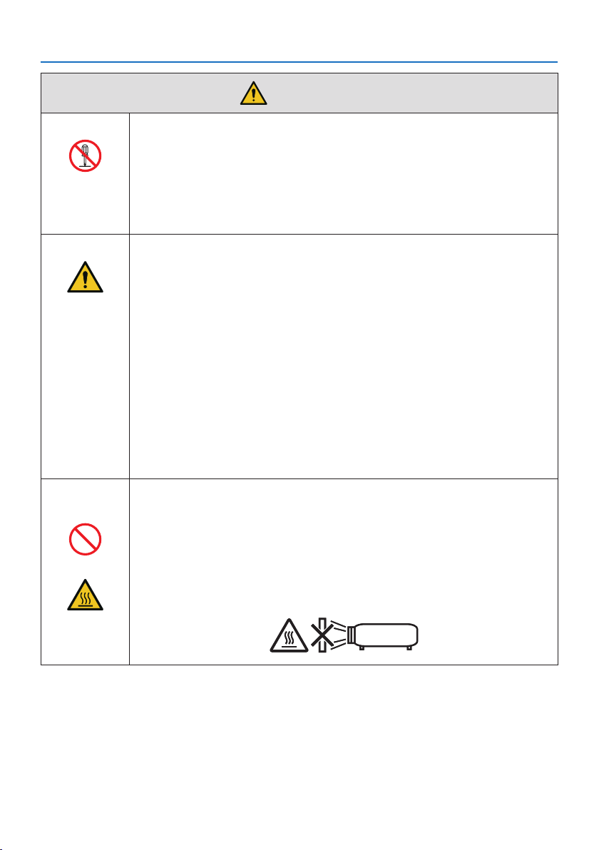
Do not place objects in front of the lens while the projector is
operating.
PROHIBITION
•Donotleavethelenscaponthelenswhiletheprojectorisoperating.The
lens cap could get hot and be warped.
•Donotplaceobjectsinfrontofthelensthatobstructthelightwhilethe
projector is operating. The object could get hot and be broken or catch fire.
•Thebelowpictogramindicatedonthecabinetmeanstheprecautionfor
avoiding to place objects in front of the projector lens.
CAUTION
FOR HIGH
TEMPERATURE
Important Information
ix
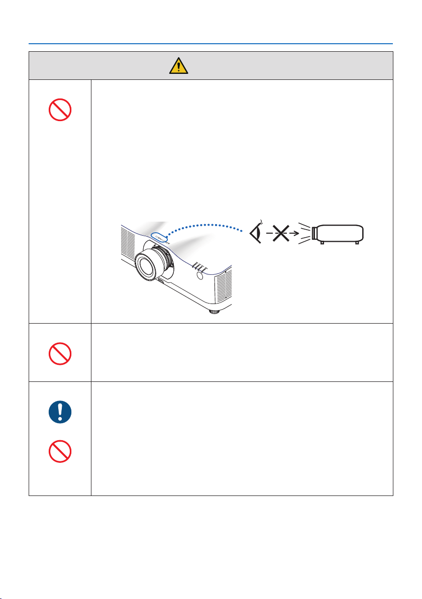
WARNING
About the projector’s light source
PROHIBITION
•Donotlookintotheprojector’slens.
Strong light that could damage your eyes is projected when the projector is
operating. Be especially careful when children are around.
•Donotlookattheprojectedlightusingopticaldevices(magnifyingglasses,
reflectors, etc.). Doing so could result in vision impairment.
•Checkthatthereisnoonelookingatthelenswithintheprojectionrange
before turning on the projector.
•Donotallowchildrentooperatetheprojectoralone.Whenachildisoperating
the projector an adult should always be present and watch the child carefully.
• Thefollowinggraphicsymbolindicatingthatlookingintotheprojectoris
prohibited is displayed on top of the projector above the lens mounting unit.
When cleaning the projector
PROHIBITION
•Donotuseammablegasspraystoremovedustfromthelens,cabinet,etc.
Doing so could lead to fire.
About option cover (separately sold)
BE SURE TO DO
•Besuretotightenthescrewsafterattachingtheoptioncover.Failuretodoso
may cause the cable cover to come off and fall, resulting in injury or damage
to the cable cover.
PROHIBITION
•Donotputbundledcablesintheoptioncover.Doingsomaydamagethe
power cord, resulting in a fire.
•Donotholdtheoptioncoverwhilemovingtheprojectorordonotapply
excessive force to the option cover. Doing so may damage the option cover,
resulting in injury.
Important Information
x
CAUTION
Connecting the power cord to earth
BE SURE TO DO
•Thisequipmentisdesignedtobeusedintheconditionofthepowercord
connected to earth. If the power cord is not connected to the earth, it may
cause electric shock. Please make sure the power cord is earthed properly.
Do not use a 2-core plug converter adapter.
Handling the power cord
BE SURE TO DO
•Whenconnectingthepowercordtotheprojector’sACINterminal,makesure
the connector is fully and firmly inserted. Be sure to fix the power cord using
the power cord stopper. Loose connection of the power cord could lead to
fire or electric shock.
DO NOT TOUCH
WITH WET
HANDS
•Donotconnectordisconnectthepowercordwithwethands.Doingsocould
result in electric shock.
UNPLUG THE
POWER CORD
•Whencleaningtheprojector,forsafetypurposesunplugthepowercordfrom
the power outlet beforehand.
•Whenmovingtheprojector,rstbesuretoturnothepower,unplugthe
power cord from the power outlet and check that all connection cables con-
necting the projector to other devices have been disconnected.
•Whenplanningnottousetheprojectorforlongperiodsoftime,always
unplug the power cord from the power outlet.
Do not use on networks subject to overvoltage.
PROHIBITION
•Connecttheprojector’sEthernet/HDBaseT port and LAN port to a network
for which there is no risk of overvoltage being applied.
Overvoltage applied to the Ethernet/HDBaseT or LAN port could result in
electric shock.
Lens shift, focus and zoom operations
BE SURE TO DO
•Whenshiftingthelensoradjustingthefocusorzoom,dosofromeither
behind or to the side of the projector. If adjustments are performed from the
front, your eyes could be exposed to strong light and get injured.
•Keepyourhandsawayfromthelensareawhenperformingthelensshiftop-
eration. If not, your fingers could get caught in the gap between the cabinet
and the lens.
Important Information
xi
CAUTION
Handling batteries
PROHIBITION
•Handlebatterieswithcaution.Failuretodosocouldleadtore,injuryor
contamination of the surroundings.
- Do not short-circuit or take apart batteries or dispose of them in flames.
- Do not use batteries other than those specified.
- Do not use new batteries together with old ones.
- When inserting batteries, pay attention to the polarities (+ and − directions),
and be sure to insert them as indicated.
•Contactyourdealerorlocalauthoritieswhendisposingofbatteries.
About the vents
PROHIBITION
•Donotobstructtheprojector’svents.Also,donotplacesuchsoftobjectsas
paper or cloths underneath the projector. Doing so could lead to fire.
Leave sufficient space between the place where the projector is installed and
its surroundings. (→ page
xxii)
•Donottouchtheexhaustventareawhileprojectingorimmediatelyafter
projecting images. The exhaust vent area may be hot at this time and touch-
ing it could cause burns.
CAUTION
FOR HIGH
TEMPERATURE
Moving the projector
PROHIBITION
•Formovingtheprojector,makesureyouhaveatleasttwopeople.Attempting
to move the projector alone could result in back pain or other injuries.
•Whenmovingtheprojector,donotholdthelenssection.Thefocusring
could turn, causing the projector to drop and resulting in injury. Also, if you
put your hand on the gap between the cabinet and the lens, the projector
may be damaged, falling and causing injury.
•Whencarryingtheprojectorwiththelensunitremoved,donottouchthe
mounting area of the lens with your hands. Also, do not put your hand into
the recess of the connection terminal. The projector could be damaged or
fall down, resulting in injuries.
•Whenmovingtheprojectorwiththeoptioncoverattached,donotholditby
the option cover. The option cover could come lose and the main unit could
fall down, causing injuries.
Inspecting the projector and cleaning the inside
BE SURE TO DO
•Consultwithyourdealeraboutonceperyearforcleaningoftheinsideofthe
projector. Dust could accumulate inside of the projector if it is not cleaned
for extended periods of time, leading to fires or malfunction.
Important Information
xii
CAUTION
Attaching/detaching the lens
BE SURE TO DO
•Turnotheprojectorbeforeattachingordetachingthelensunit.Failureto
do so could result in visual impairment.
Securing the lens unit with the fall prevention wire
BE SURE TO DO
•Iftheprojectorisgoingtobesuspendedfromaceilingoranotherhighplace,
secure the lens unit using the fall prevention wire (sold separately). If the lens
unit is not secured, it may fall down if it comes lose.
About viewing 3D pictures
BE SURE TO DO
•Beforeviewing,besuretoreadhealthcareprecautionsthatmaybefoundin
the user’s manual included with your 3D eyeglasses or your 3D compatible
content such as Blu-ray Discs, video games, computer’s video files and the
like.
•Toavoidanyadversesymptoms,heedthefollowing:
- Do not use 3D eyeglasses for viewing any material other than 3D images.
- Allow a distance of 2 m/7 feet or greater between the screen and a user.
Viewing 3D images from too close a distance can strain your eyes.
- Avoid viewing 3D images for a prolonged period of time. Take a break of
15 minutes or longer after every hour of viewing.
- If you or any member of your family has a history of light-sensitive seizures,
consult a doctor before viewing 3D images.
- While viewing 3D images, if you get sick such as nausea, dizziness, queasi-
ness, headache, eyestrain, blurry vision, convulsions, and numbness, stop
viewing them. If symptoms still persist, consult a doctor.
•View3Dimagesfromthefrontofthescreen.Viewingfromananglemay
cause fatigue or eyestrain.

Important Information
xiii
Laser Safety Caution
For USA
WARNING – CLASS 3R OF IEC 60825-1 SECOND EDITION LASER PRODUCT
LASERRADIATION–AVOIDDIRECTEYEEXPOSURE
•Useofcontrolsoradjustmentsorperformanceofproceduresotherthanthosespeciedherein
may result in hazardous radiation exposure.
•ThisproductisclassiedasClass3RofIEC60825-1Secondedition2007-03
Complies with FDA performance standards for laser products except for deviations pursuant to
Laser Notice No. 50, dated June 24, 2007.
For other regions
WARNING
CLASS 1 LASER PRODUCT OF IEC 60825-1 THIRD EDITION
•Thelasermoduleisequippedinthisproduct.Useofcontrolsoradjustmentsofprocedures
other than those specified herein may result in hazardous radiation exposure.
WARNING
RG3 PRODUCT OF IEC/EN 62471-5 FIRST EDITION
•Nodirectexposuretothebeamshallbepermitted,RG3IEC/EN62471-5:2015.
•Operatorsshallcontrolaccesstothebeamwithinthehazarddistanceandinstalltheproduct
at the height that will prevent exposures of spectators’ eyes within the hazard distance.
•ThisproductisclassiedasClass1ofIEC60825-1Thirdedition2014-05andRG3ofIEC/EN62471-5
First edition.
Obey the laws and regulations of your country in relation to the installation and management of
the device.
Light Module
•Alightmodulecontainingmultiplelaserdiodesisequippedintheproductasthelightsource.
•Theselaserdiodesaresealedinthelightmodule.Nomaintenanceorserviceisrequiredforthe
performance of the light module.
•Enduserisnotallowedtoreplacethelightmodule.
•Contactqualieddistributorforlightmodulereplacementandfurtherinformation.
•Outlineoflaseremittedfromthebuilt-inlightmodule:
-Wavelength:455nm
-Maximumpower:257W(PA1004UL-W/PA1004UL-B),229W(PA804UL-W/PA804UL-B)
•Radiationpatternfromtheprotectivehousing:
-Wavelength:455nm
-Maximumlaserradiationoutput:333mW
Important Information
xiv
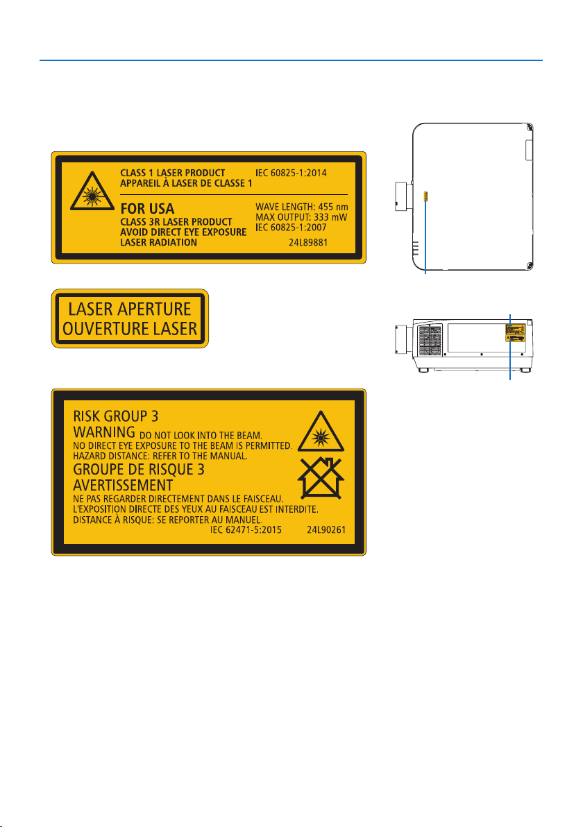
Label Information
•Thecautionandtheexplanatorylabelsarestuckonthebelowindicatedpositions.
For USA
Label 1
Label 2
Label 3
Label 1
Label 2
For other regions
Label 3
Important Information
xv
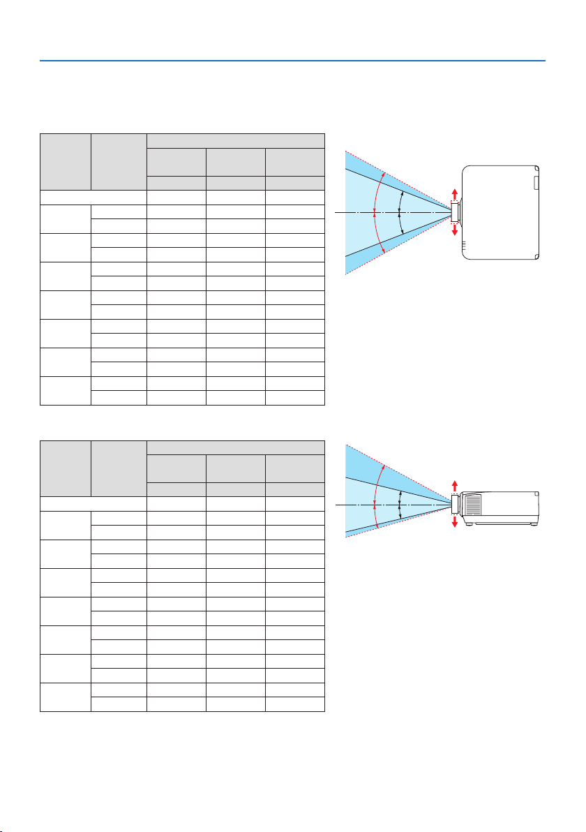
Laser light radiation range
The figure below shows the maximum radiation range of the laser light.
Horizontalangle(unit:degree)
Lens unit Zoom
Lens position
Right most
Center (Refer-
ence value)
Left most
HR HC HL
NP11FL 31.8 31.8 31.8
NP12ZL
Tele 27.4 18.0 27.4
Wide 34.0 22.9 34.0
NP13ZL
Tele 15.1 9.6 15.1
Wide 28.3 18.6 28.3
NP14ZL
Tele 9.6 6.0 9.6
Wide 15.1 9.6 15.1
NP15ZL
Tele 6.4 4.0 6.4
Wide 9.7 6.1 9.7
NP40ZL
Tele 31.7 23.8 31.7
Wide 41.0 31.8 41.0
NP41ZL
Tele 13.0 9.4 13.0
Wide 27.9 20.7 27.9
NP43ZL
Tele 6.8 4.9 6.8
Wide 13.4 9.7 13.4
HC
HR
HL
HC
Left
Right
Verticalangle(unit:degree)
Lens unit Zoom
Lens position
Upper most
Center (Refer-
ence value)
Lower most
VU VC VD
NP11FL 21.2 21.2 21.2
NP12ZL
Tele 24.0 11.5 13.7
Wide 30.1 14.8 17.6
NP13ZL
Tele 13.0 6.0 7.2
Wide 24.8 11.9 14.1
NP14ZL
Tele 8.3 3.8 4.5
Wide 13.1 6.0 7.2
NP15ZL
Tele 5.5 2.5 3.0
Wide 8.4 3.8 4.6
NP40ZL
Tele 28.9 15.4 18.3
Wide 37.8 21.2 24.9
NP41ZL
Tele 11.6 5.9 7.0
Wide 25.3 13.3 15.8
NP43ZL
Tele 6.1 3.0 3.7
Wide 12.0 6.1 7.3
VC
VC
VU
VD
Lower
Upper
Important Information
xvi
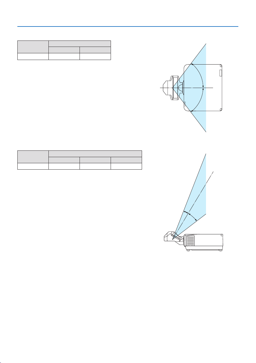
Horizontalangle(unit:degree)
Lens unit
Zoom
Tele Wide
NP44ML
— 55.8
H
H
Verticalangle(unit:degree)
Lens unit
Zoom
Tele V1 V2
NP44ML — 10.7 24.6
V
1
V
2

Important Information
xvii
Cable information
Use shielded cables or cables attached ferrite cores so as not to interfere with radio and television
reception.
For details, please refer to “5. Making Connections” in this user’s manual.
FCC Information
WARNING
• TheFederalCommunicationsCommissiondoesnotallowanymodicationsorchangestothe
unit EXCEPT those specified by NEC Display Solutions of America, Inc. in this manual. Failure
to comply with this government regulation could void your right to operate this equipment.
•ThisequipmenthasbeentestedandfoundtocomplywiththelimitsforaclassAdigitaldevice,
pursuant to Part 15 of the FCC Rules. These limits are designed to provide reasonable protection
against harmful interference when the equipment is operated in a commercial environment.
This equipment generates, uses, and can radiate radio frequency energy and, if not installed
and used in accordance with the instruction manual, may cause harmful interference to radio
communications. Operation of this equipment in a residential area is likely to cause harmful
interference in which case the user will be required to correct the interference at his own
expense.
Supplier’s declaration of conformity (for USA only)
This device complies with Part 15 of the FCC Rules. Operation is subject to the following two
conditions.
(1) This device may not cause harmful interference, and (2) this device must accept any interfer-
ence received, including interference that may cause undesired operation.
U.S.ResponsibleParty:NEC Display Solutions of America, Inc.
Address:3250 Lacey Rd, Ste 500
Downers Grove, IL 60515
TelephoneNumber:630-467-3000
TypeofProduct:Projector
EquipmentClassication:Class A Peripheral
ModelNumber:NP-PA1004UL-W/NP-PA1004UL-B/
NP-PA804UL-W/NP-PA804UL-B

Important Information
xviii
Cautions for ensuring the projector’s performance
•Donotinstallinplacessubjecttovibrationsorshocks.
If installed in places where the vibrations from power sources and the like are conveyed, or in
vehicles or on vessels, etc. the projector could be affected by vibrations or shocks that may dam-
age internal parts and lead to malfunction.
Install in a place not subject to vibrations or shocks.
•Donotinstallnearhighvoltagepowerlinesorpowersources.
The projector may be affected by interference if it is installed near a high voltage power line or
a power source.
•Donotinstallorstoreinsuchplacesasthosedescribedbelow.Doingsocouldleadtomalfunc-
tion.
- Places where strong magnetic fields are generated
- Places where corrosive gases are generated
•Ifintenselightlikelaserbeamsentersfromthelens,itcouldleadtomalfunction.
•Consultyourdealerbeforeusinginplaceswheremuchcigarettesmokeordustispresent.
•Select[HIGH] in [FAN MODE] if you continue to use the projector for consecutive days.
•Whenthesamestillimageisprojectedforalongperiodoftimewithacomputer,etc.thepattern
of the image may remain on the screen after the projection is stopped, but it will disappear after
a while. This happens due to the properties of liquid crystal panels, and is not a malfunction. We
recommend using a screensaver on the computer side.
•Whenusingtheprojectorataltitudesofabout5500feet/1700metersorhigher,besuretoset
the [FAN MODE] to [HIGH ALTITUDE]. If not, the inside of the projector may get hot, leading to
malfunction.
•Whentheprojectorisusedathighaltitudes(placeswheretheatmosphericpressureislow),it
may be necessary to replace the optical parts sooner than usual.
•Aboutmovingtheprojector
- Remove the lens unit once, and be sure to attach the lens cap so as not to scratch the lens. Also,
attach a dust protective cap to the projector.
- Do not subject the projector to vibrations or strong shocks.
The projector could be damaged otherwise.
•Donotusethetiltfeetforpurposesotherthanadjustingtheprojector’stilt.
Improper handling, such as carrying the projector by the tilt feet or using it leaned against a wall,
could lead to malfunction.
•Donottouchthesurfaceoftheprojectionlenswithbarehands.
Fingerprints or dirt on the surface of the projection lens will be enlarged and projected on the
screen. Do not touch the surface of the projection lens.
•Donotunplugthepowercordfromtheprojectororthepoweroutletwhileprojecting.Doingso
could cause deterioration of the projector’s AC IN terminal or power plug contact. To interrupt
the AC power supply while images are being projected, use a power strip switch, a breaker, etc.
•Abouthandlingoftheremotecontrol
- The remote control will not work if the projector’s remote signal sensor or the remote control’s
signal transmitter is exposed to strong light or if there are obstacles between them that obstruct
the signals.
- Operate the remote control from within 20 meters from the projector, pointing it at the projec-
tor’s remote signal sensor.
- Do not drop the remote control or handle it improperly.
Important Information
xix
- Do not let water or other liquids get on the remote control. Should the remote control get wet,
wipe it off immediately.
- Avoid using in hot and humid places as far as possible.
- When planning not to use the remote control for long periods of time, remove both batteries.
•Takemeasurestopreventexternallightfromshiningonthescreen.
Make sure only the light from the projector shines on the screen. The less external light on the
screen, the higher the contrast and the more beautiful the images.
•Aboutscreens
Images will not be clear if there is dirt, scratches, discoloration, etc. on your screen. Handle the
screen with care, protecting it from volatile substances, scratches and dirt.
Precautions when installing the projector at an angle
This projector can be installed universally in every angle. When installing the projector at the angles
shown below, the separately sold option cover is required to be attached to the projector.
WARNING
• Forsafetyreasons,besuretoattachtheoptioncover.
• Besuretoattachtheoptioncovertotheprojectorwhentheprojector’spoweristurnedon.
This may result in fire.
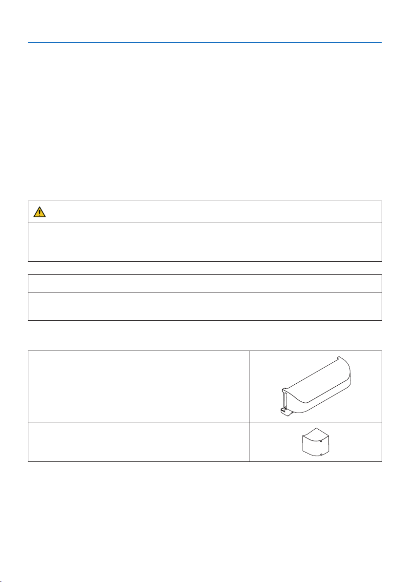
Model name of option cover
NP13CV-W for PA1004UL-W/PA804UL-W
NP13CV-B for PA1004UL-B/PA804UL-B
Two covers are packaged with the option cover NP13CV-W and NP13CV-B.
OptioncoverA:forattachingtotheconnectionterminal
area
OptioncoverB:forattachingtotheexhaustvent
Important Information
xx
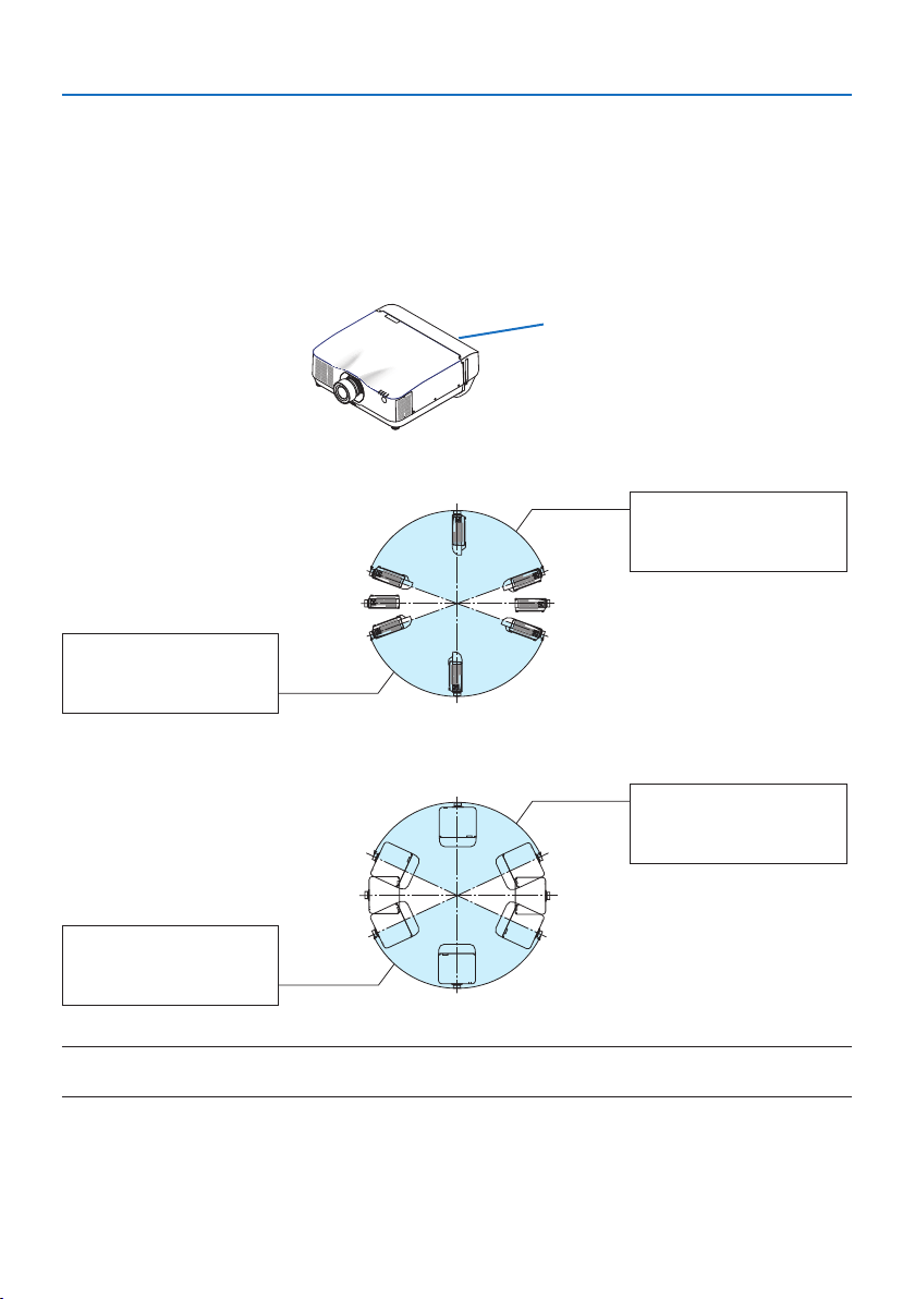
The drawings below show the installation angle required to attach the option cover A and B re-
spectively.
•BothoptioncoverAandBmayneedtobeattacheddependingontheinstallationpositionof
the projector.
•Whethertheoptioncoverneedstobeattachedinthecurrentinstallationpositioncanbechecked
on the [INFO.] screen of the on-screen menu (→ pages
157, 158).
Installation angles required to attach the option cover A
Option cover A
In the direction of back and forth
20°–150°
Option cover A must be
attached
90°
270°
180° 0°
200°–330°
Option cover A must be
attached
In the direction of left and right
20°–160°
Option cover A must be
attached
90°
270°
180° 0°
200°–340°
Option cover A must be
attached
NOTE:
•Thedrawingsshowtheimageofinstallationangleasareference.Theyareslightlydierentfromtheactualone.
Important Information
xxi
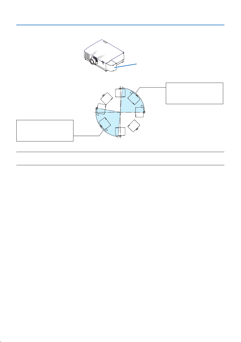
Installation angles required to attach the option cover B
Option cover B
0°–85°
Option cover B must be
attached
90°
270°
180° 0°
170°–265°
Option cover B must be
attached
NOTE:
•Thedrawingsshowtheimageofinstallationangleasareference.Theyareslightlydierentfromtheactualone.
Important Information
xxii
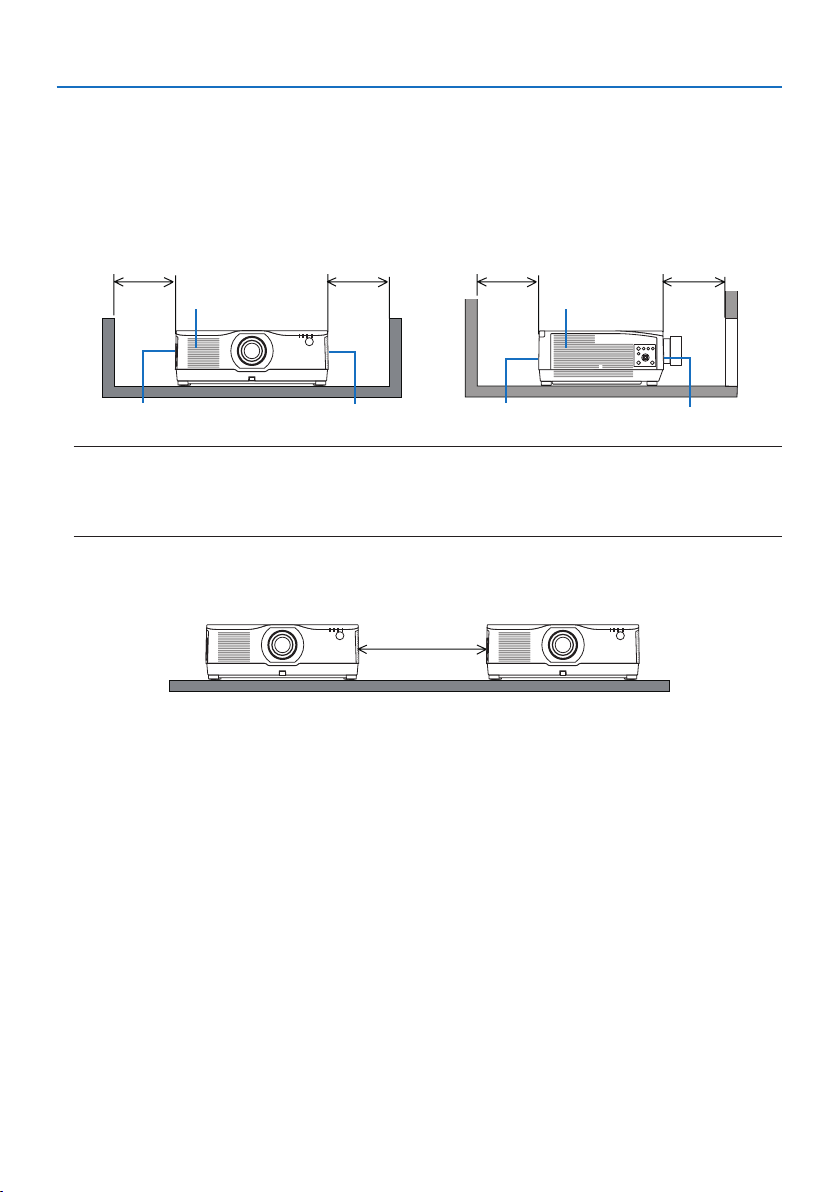
Clearance for Installing the Projector
•Wheninstallingtheprojector,keepsucientspacearoundit,asdescribedbelow.Ifnot,thehot
exhaust emitted from the projector may be taken back in.
Also, make sure no wind from an air-conditioner hits the projector.
The projector’s heat control system may detect an abnormality (temperature error) and automati-
cally shut off the power.
Exhaust vent
Intake vent Exhaust vent
Intake ventExhaust vent Intake vent
30 cm/12" or greater 20 cm/8" or greater20 cm/8" or greater 30 cm/12" or greater
NOTE:
•Intheabovegure,itisassumedthatthereissucientspaceabovetheprojector.
•Fortheportraitprojection,eachrequiredclearancebetweentheoorandtheintakeortheexhaustventissamewiththe
clearanceontheupperillustration.Seepage210foraninstallationexampleonportraitprojection.
•Whenusingmultipleprojectorstogetherformulti-screenprojection,providesucientspace
around the projectors for air intake and exhaust. When the intake and exhaust vents are obstructed,
the temperature inside the projector will rise and this may result in a malfunction.
Precautions for Ceiling Installation
Do not install the projector in the following places. Attached substances such as oil, chemicals and
moisture may cause deformation or cracks of the cabinet, corrosion of the metal parts, or malfunction.
• Outdoorsandplaceswithhumidordust
• Placesexposedtooilsmokeorsteam
• Placeswherecorrosivegasesaregenerated
About Copyright of original projected pictures:
Please note that using this projector for the purpose of commercial gain or the attraction of public
attention in a venue such as a coffee shop or hotel and employing compression or expansion of the
screen image with the following functions may raise concern about the infringement of copyrights
which are protected by copyright law.
[ASPECT RATIO], [KEYSTONE], Magnifying feature and other similar features.
[AUTO POWER OFF] Function
The factory default setting for [AUTO POWER OFF] is 15 minutes. If no input signal is received and no
operation is performed on the projector during 15 minutes, the projector is automatically powered
off for saving the power consumption. In order to control the projector by an external device, set
the [AUTO POWER OFF] to [OFF]. Please refer page
154 for details.

Important Information
xxiii
Trademarks
•NaViSet,ProAssist,andVirtualRemotearetrademarksorregisteredtrademarksofNECDisplay
Solutions, Ltd. in Japan, in the United State and other countries.
•Apple,Mac,iMac,andMacBookaretrademarksofAppleInc.registeredintheU.S.andother
countries.
•Microsoft,Windows,andPowerPointareeitheraregisteredtrademarkortrademarkofMicrosoft
Corporation in the United States and/or other countries.
•ThetermsHDMIandHDMIHigh-DenitionMultimediaInterface,andtheHDMILogoaretrade-
marks or registered trademarks of HDMI Licensing Administrator, Inc. in the United States and
other countries.
•DisplayPortandDisplayPortComplianceLogoaretrademarksownedbytheVideoElectronics
Standards Association.
•HDBaseT™isatrademarkofHDBaseTAlliance.
•TrademarkPJLinkisatrademarkappliedfortrademarkrightsinJapan,theUnitedStatesofAmerica
and other countries and areas.
•Blu-rayisatrademarkofBlu-rayDiscAssociation.
•CRESTRONandCRESTRONROOMVIEWaretrademarksorregisteredtrademarksofCrestron
Electronics, Inc. in the United States and other countries.
•ExtronandXTPareregisteredtrademarksofRGBSystems,Inc.intheUnitedStates.
•EthernetiseitheraregisteredtrademarkortrademarkofFujiXeroxCo.,Ltd.
•Art-NetisanEthernetprotocolinventedbyArtisticLicence.
Art-Net™DesignedbyandCopyrightArtisticLicenceHoldingsLtd.
•Otherproductandcompanynamesmentionedinthisuser’smanualmaybethetrademarksor
registered trademarks of their respective holders.
•VirtualRemoteToolusesWinI2C/DDClibrary,©NicomsoftLtd.

1
1-1. Introduction to the Projector
This section introduces you to your new projector and describes the features and controls.
General
•Liquidcrystaltypehighbrightness/highresolutionprojector
This projector has a display resolution of 1920 dots × 1200 lines (WUXGA) and an aspect ratio
of16:10.Select[BOOST] under [REF. LIGHT MODE] for a brighter screen.
Model Brightness
PA1004UL-W/PA1004UL-B NORMAL:9000lm
BOOST:10000lm
PA804UL-W/PA804UL-B NORMAL:7500lm
BOOST:8200lm
When [BOOST] is selected, the cooling fan noise increases. The life of the optical components
may also be shortened depending on the operating environment.
•Aproprietarysealedstructurethatachieveshighlydust-proofperformance
Due to its excellent dust-proof performance, the projector is not equipped with a filter. Filter
replacement is therefore unnecessary.
•Silentdesignutilizingasealedstructure
A silent design with no irritating fan noise even in a quiet conference room or classroom.
Light source · Brightness
•Along-lifelaserdiodeisequippedinthelightmodule
The product can be operated at low cost because the laser light source can be used for a long
time without requiring replacement or maintenance.
•Brightnesscanbeadjustedwithinawiderange
Unlike with ordinary light sources, the brightness can be adjusted from 50 to 100% in 1% incre-
ments.
•[CONSTANT BRIGHTNESS] mode
Brightness normally decreases with use, but by selecting [CONSTANT BRIGHTNESS] mode,
sensors inside the projector detect and automatically adjust the output, thereby maintaining
constant brightness throughout the life of the light module.
However, if brightness output is set at the maximum, brightness will decrease with use.
Installation
•Widerangeofoptionallensesselectableaccordingtotheplaceofinstallation
This projector supports 9 types of optional lenses, providing a selection of lenses adapted to a
variety of places of installation and projection methods.
Note that no lens is mounted upon shipment from the factory. Please purchase optional lenses
separately.
1. Check the product overview, supplied items and part names

1. Check the product overview, supplied items and part names
2
•360dgereefreeprojection
This projector can be installed universally in every angle.
Note, however, that the separately sold option cover is required to be attached to the projector
depending on the installation angle of the projector.
For controlling fine inclination, use the tilt foot. Install an appropriate metal and a stand that
has enough strength to support the projector for controlling the installation angle.
Videos
•Widerangeofinput/outputterminals(HDMI,DisplayPort, HDBaseT, etc.)
Theprojectorisequippedwithavarietyofinput/outputterminals:HDMI(input×2),DisplayPort,
HDBaseT(input×1,output×1),computer(analog),etc.
The projector’s HDMI input, DisplayPort input terminals and HDBaseT Ports support HDCP.
HDMI and HDBaseT support HDCP 2.2/1.4
DisplayPort supports HDCP 1.3
•Simultaneousdisplayof2images(PIP/PICTURE BY PICTURE)
Two images can be projected simultaneously with a single projector.
Therearetwotypesoflayoutsforthetwoimages:[PIP] in which a sub-picture is displayed on
the main picture, and [PICTURE BY PICTURE] in which the main and sub pictures are displayed
next to each other.
•Multi-screenprojectionusingmultipleprojectors
This projetor equips the HDBaseT IN/Ethernet and HDBaseT OUT/Ethernet ports. Multiple pro-
jectors in same brightness up to four units can be conneted in a daisy chain by a LAN* cable via
these terminals. A high quality picture is achieved by dividing and projecting high resolution
videos among the various projectors.
Furthermore, the boundaries of the screens are smoothed using an edge blending function.
* Use a commercially available CAT 5e STP cable or one in a higher specification.
•Seamlessswitchfunctionforsmootherscreenchangeswhenswitchingthesignal
When the input connector is switched, the image displayed before switching is held so that that
the new image can be switched to without a break due to absence of a signal.
•SupportsHDMI3Dformat
This projector can be used to watch videos in 3D using commercially-available active shutter-
type 3D eyewear and 3D emitters that support XPANDVISION 3D.
Network
•SupportswiredLAN
Equips the LAN and HDBaseT/Ethernet (RJ-45) ports. Utilizing a wired LAN connected with these
ports, it enables to control the projector by a computer.

1. Check the product overview, supplied items and part names
3
•CRESTRON ROOMVIEW and Extron XTP compatibility
The projector supports CRESTRON ROOMVIEW and Extron XTP, allowing multiple devices con-
nected in the network to be managed and controlled from a computer. Moreover, it enables to
output and control image via an Extron XTP transmitter connected with the projector.
•Compatiblewithoursoftwareapplications(NaViSet Administrator 2, ProAssist, Virtual Remote
Tool, etc.). The projector can be controlled from a computer connected via a wired LAN.
•NaViSet Administrator 2
You can monitor the status of the projector and control a variety of functions.
•ProAssist
Necessary adjustments can be made smoothly for multi-screen projection.
•Virtual Remote Tool
A virtual remote control is displayed on the computer screen to perform simple controls
such as turning the projector on/off, switching signals, etc. It is also possible to change the
background logo of the projector. (→ page
190)
Please visit our web site for downloading each software.
URL:
https://www.nec-display.com/dl/en/index.html
Energy-saving
•Energy-savingdesignwithastandbypowerconsumptionof0.22W(100-130VAC)/0.28
W (200-240 V AC)
Selecting [ON] for [POWER-SAVING] from the menu can put the projector in power-saving mode.
Whennetworkisenabled:0.8W
Whenthenetworkisdisabled:0.22W(100-130VAC)/0.28W(200-240VAC)
•[LIGHT MODE] for low power consumption and “Carbon Meter” display
The projector is equipped with an [REF. LIGHT MODE] for reducing power consumption during
use. Furthermore, the power-saving effect when one option among [ECO1] and [ECO2] is set is
converted into the amount of reductions of CO
2
emissions and this is indicated on the confirma-
tion message displayed when the power is turned off and at [INFORMATION] on the on-screen
menu (CARBON METER).
1. Check the product overview, supplied items and part names
4
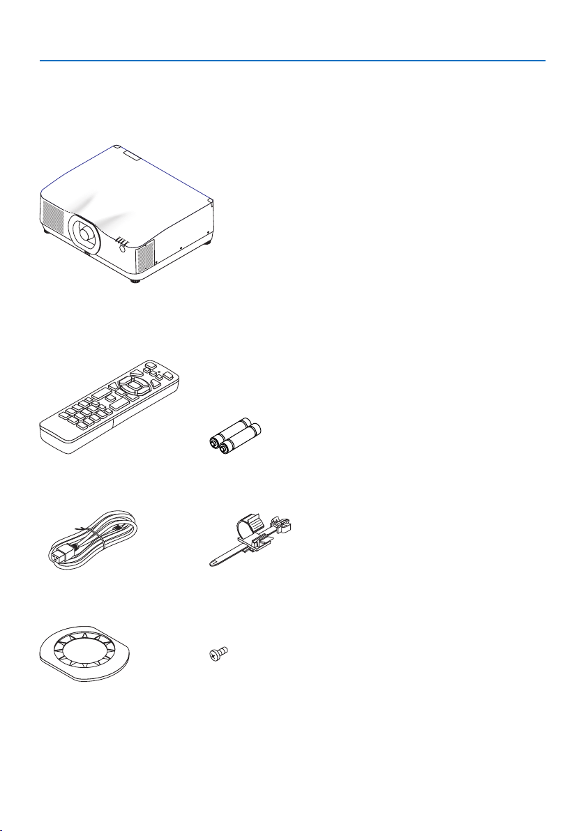
1-2. What’s in the Box?
Make sure your box contains everything listed. If any pieces are missing, contact your dealer.
Please save the original box and packing materials if you ever need to ship your projector.
Projector
Dust cap for lens
(24F56481)
* The projector is shipped without a lens. For the types of lens and throw distances, see page 171.
Remote control
(7N901321)
AAA alkaline batteries (x2)
Power cord
(7N080533)
Power cord stopper
(24C10881)
Lens mask
(24FU2831)
Lens theft prevention screw
(24V00941)

1. Check the product overview, supplied items and part names
5
•ImportantInfomation
(ForUSA:7N8R0161,ForCanada/SouthAmerica:7N8R0511)
•QuickSetupGuide
(7N8R0171)
•SecuritySticker
(Use this sticker when security password is set on.)
•Limitedwarranty
1. Check the product overview, supplied items and part names
6
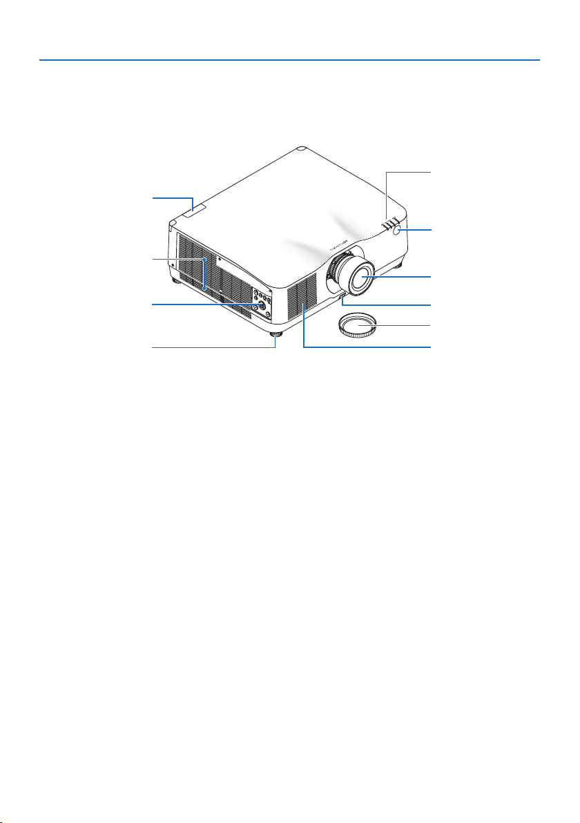
1-3. Part Names of the Projector
Front
The lens is sold separately. The description below is for when the NP41ZL lens is mounted.
1
2
3
8
6
5
4
7
6
9
1. Exhaust vent
Heated air is exhausted from here
(→ page
xxii, 170)
2. Controls
(→ page 8)
3. Adjustable Tilt Foot
4. Intake vent
(→ page
xxii, 170)
5. Indicator Section
(→ page 8, 191)
6. Remote Sensor
(→ page 14)
7. Lens
8. Lens Cap
(The optional lens is shipped with the lens
cap.)
9. Lens Release Button
(→ page
206)
1. Check the product overview, supplied items and part names
7
* Security and theft protection lock compatible with Kensington security cables/equipment. For products,
visit Kensington’s website.
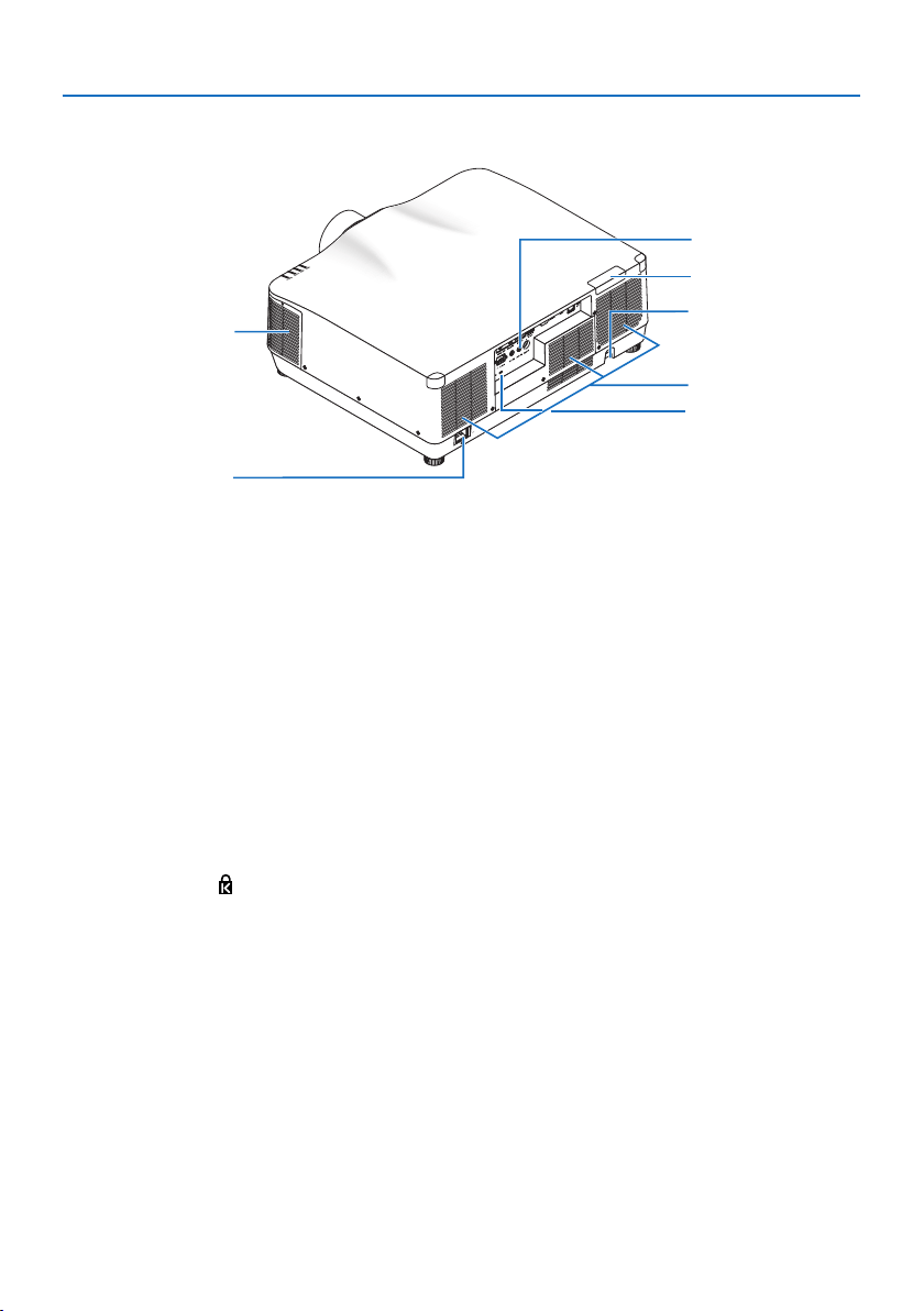
Rear
1
7
2
3
4
6
5
1. Exhaust vent
(→ page
xxii, 170)
2. Intake vent
(→ page xxii, 170)
3. Security Bar
Attach an anti-theft device. The security bar
accepts security wires or chains up to 0.18
inch/4.6 mm in diameter.
4. Remote Sensor
(located on the front and the rear)
(→ page
14)
5. Security Slot (
)*
6. Terminals
(→ page 9)
7. AC IN Terminal
Connect the supplied power cord’s three-
pin plug here, and plug the other end into
an active wall outlet.
(→ page
17)
1. Check the product overview, supplied items and part names
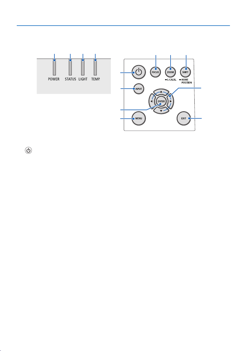
8
Controls/Indicators
2 3 4 5
10
7
8
1
6
9
11 12
13
1. (POWER) Button
Switches between projector’s power on and
standby.
(→ page
20, 37)
2. POWER Indicator
(→ page 17, 20, 37, 191)
3. STATUS Indicator
(→ page 191)
4. LIGHT Indicator
(→ page 191)
5. TEMP. Indicator
(→ page 191)
6. INPUT Button
(→ page 23)
7. MENU Button
(→ page 82)
8. ▲▼◀▶ / Volume Buttons ◀▶
(→ page
27, 36, 82)
9. ENTER Button
(→ page
82)
10. EXIT Button
(→ page 82)
11. FOCUS Button
(→ page 31)
12. ZOOM/L-CALIB. Button
(→ page
21, 34)
13. SHIFT/HOME POSITION Button
(→ page 27)
1. Check the product overview, supplied items and part names
9
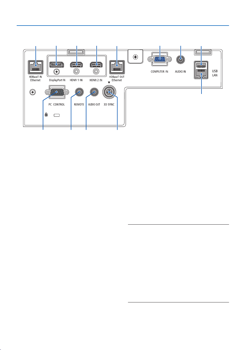
Terminal Panel Features
2731 45
81112 13
10
6 9
1. HDMI 1 IN Terminal (Type A)
(→ page
161, 163, 165)
2. HDMI 2 IN Terminal (Type A)
(→ page 161, 163, 165)
3. DisplayPort IN Terminal
(→ page 161)
4. COMPUTER IN/ Component Input Termi-
nal (Mini D-Sub 15 Pin)
(→ page 160, 164)
5. COMPUTER AUDIO IN Mini Jack (Stereo
Mini)
(→ page 160, 163)
6. HDBaseT IN/Ethernet Port (RJ-45)
(→ page 166, 167)
7. HDBaseT OUT/Ethernet Port (RJ-45)
(→ page 167)
8. AUDIO OUT Mini Jack (Stereo Mini)
(→ page 163, 165)
9. USB-A Port (Type A)
(→ page
48)
10. LAN Port (RJ-45)
(→ page
168)
11. 3D SYNC Terminal (Mini DIN 3 Pin)
(→ page 53)
12. PC CONTROL Port (D-Sub 9 Pin)
(→ page
189)
Use this port to connect a PC or control
system. This enables you to control the pro-
jector using serial communication protocol.
If you are writing your own program, typical
PC control codes are on page
197.
13. REMOTE Terminal (Stereo Mini)
Use this terminal for wired remote control
of the projector.
(→ page
15)
NOTE:
•WhenaremotecontrolcableisconnectedtotheREMOTE
terminal,infraredremotecontroloperationscannotbe
performed.
•When[HDBaseT]isselectedinthe[REMOTESENSOR]andthe
projectorisconnectedtoacommercially-availabletransmis-
siondevicethatsupportsHDBaseT,remotecontroloperations
ininfra-redcannotbecarriedoutiftransmissionofremote
controlsignalshasbeensetupinthetransmissiondevice.
However,remotecontrolusinginfraredrayscanbecarried
outwhenthepowersupplyofthetransmissiondeviceis
switchedo.
1. Check the product overview, supplied items and part names
10
1-4. Part Names of the Remote Control
112
3
5
4
7
6
9
8
12
15
14
10
11
13
16
17
20
21
18
19
25
27
28
31
23
26
30
29
24
22
32
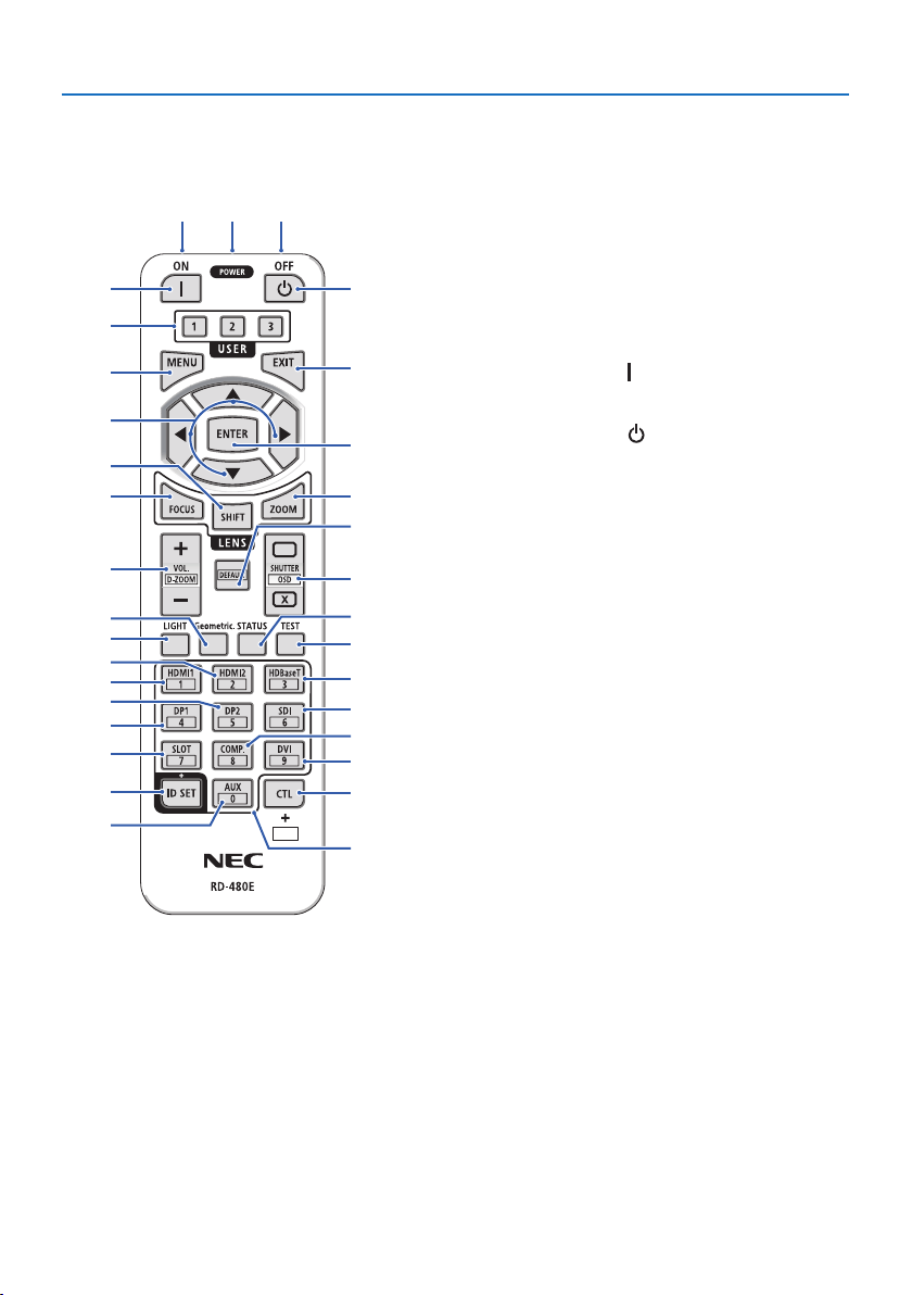
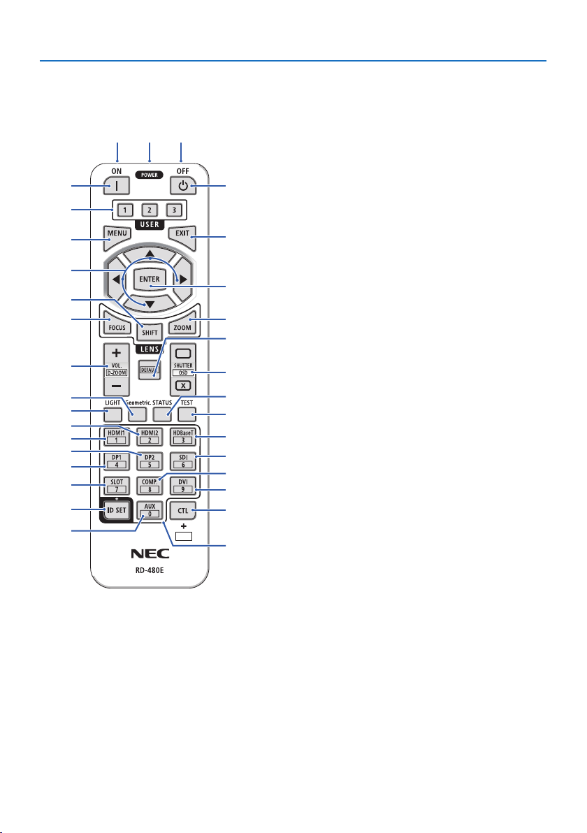
1. Infrared Transmitter
(→ page
14)
2. Remote Jack
Connect a commercially available remote cable
here for wired operation.
(→ page
15)
3. POWER ON Button (
)
(→ page
20)
4. POWER OFF Button (
)
(→ page
37)
5. USER 1/2/3 Button
(Not available on this series of projectors. For future
expansion)
6. MENU Button
(→ page 82)
7. EXIT Button
(→ page 82)
8. ▲▼◀▶ Button
(→ page 82)
9. ENTER Button
(→ page 82)
10. FOCUS Button
Applicablelensunit:NP40ZL/NP41ZL/NP43ZL/
NP44ML
(→ page
31)
11. SHIFT Button
(→ page
27)
12. ZOOM Button
Applicablelensunit:NP40ZL/NP41ZL/NP43ZL/
NP44ML
(→ page
34)

1. Check the product overview, supplied items and part names
11
13. VOL./D-ZOOM (+)(−) Button
(→ page
36, 40)
14. DEFAULT Button
(Not available on this series of projectors. For future
expansion)
15. SHUTTER/OSD OPEN (
)/CLOSE ( ) Button
(→ page
39)
16. LIGHT Button
(→ page 42)
17. Geometric. Button
(→ page 45, 113)
18. STATUS Button
(→ page 156)
19. TEST Button
(→ page 92)
20. HDMI1 Button
(→ page 23)
21. HDMI2 Button
(→ page 23)
22. HDBaseT Button
(→ page 23)
23. DP1 Button
(→ page 23)
24. DP2 Button
(Not available on this series of projectors.)
25. SDI Button
(Not available on this series of projectors.)
26. SLOT Button
(Not available on this series of projectors.)
27. COMP. Button
(→ page
23)
112
3
5
4
7
6
9
8
12
15
14
10
11
13
16
17
20
21
18
19
25
27
28
31
23
26
30
29
24
22
32
1. Check the product overview, supplied items and part names
12
28. DVI Button
(Not available on this series of projectors.)
29. AUX Button
(Not available on this series of projectors. For future
expansion)
30. ID SET Button
(→ page
139)
31. Numeric Keypad Button
(→ page 139)
32. CTL Button
(→ page 39, 40)
112
3
5
4
7
6
9
8
12
15
14
10
11
13
16
17
20
21
18
19
25
27
28
31
23
26
30
29
24
22
32
1. Check the product overview, supplied items and part names
13
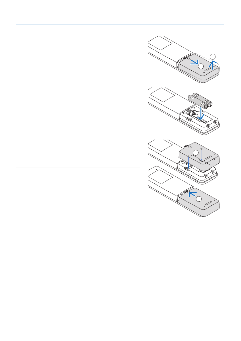
Battery Installation
1. Press the catch and remove the battery cover.
1
2
2. Install new ones (AAA). Ensure that you have the
batteries’ polarity (+/−) aligned correctly.
3. Slip the cover back over the batteries until it snaps
into place.
NOTE:
•Donotmixdierenttypesofbatteriesornewandoldbatteries.
1
2
Remote Control Precautions
•Handletheremotecontrolcarefully.
•Iftheremotecontrolgetswet,wipeitdryimmediately.
•Avoidexcessiveheatandhumidity.
•Donotshort,heat,ortakeapartbatteries.
•Donotthrowbatteriesintore.
•Ifyouwillnotbeusingtheremotecontrolforalongtime,removethebatteries.
•Ensurethatyouhavethebatteries’polarity(+/−)alignedcorrectly.
•Donotusenewandoldbatteriestogether,orusedierenttypesofbatteriestogether.
•Disposeofusedbatteriesaccordingtoyourlocalregulations.
•Pleasenotethatifmultipleprojectorsareinstallednearby,otherprojectorsmayunintentionally
light up when you turn on the power using the remote control.
1. Check the product overview, supplied items and part names
14
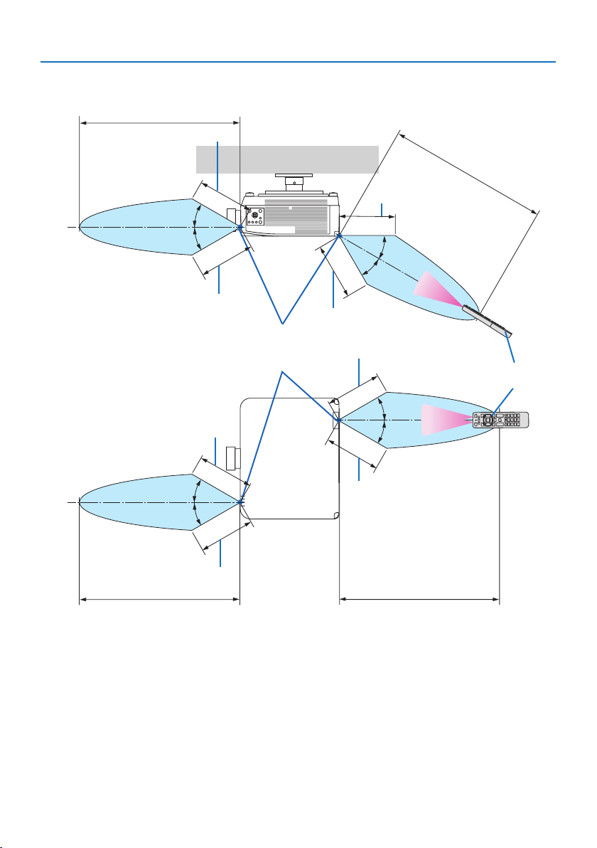
Operating Range for Wireless Remote Control
20 m/787 inch
20 m/787 inch
Remote control
Remote sensor on projector cabinet
20 m/787 inch
20 m/787 inch
7 m/276 inch
7 m/276 inch
7 m/276 inch
7 m/276 inch
7 m/276 inch
30°
30°
30°
30°
30°
30°
30°
30°
7 m/276 inch
7 m/276 inch
7 m/276 inch
•Theprojectorwillnotrespondifthereareobjectsbetweentheremotecontrolandthesensor,
or if strong light falls on the sensor. Weak batteries will also prevent the remote control from
properly operating the projector.
1. Check the product overview, supplied items and part names
15
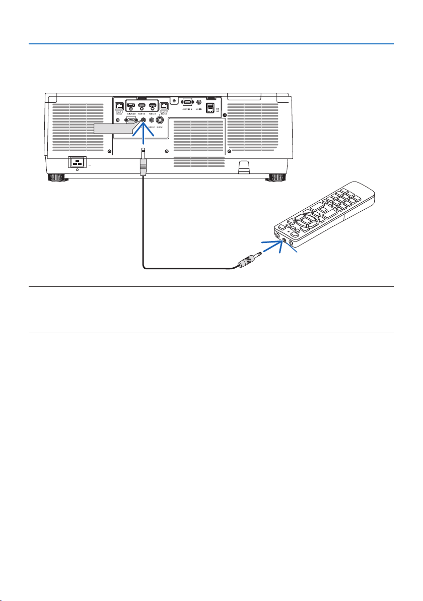
Using the Remote Control in Wired Operation
Connect one end of the remote cable to the REMOTE terminal and the other end to the remote
jack on the remote control.
REMOTE
Remote jack
NOTE:
•WhenaremotecableisinsertedintotheREMOTEterminal,theremotecontroldoesnotworkforinfraredwirelesscommunication.
•PowerwillnotbesuppliedtotheremotecontrolbytheprojectorviatheREMOTEjack.Batteryisneededwhentheremotecontrol
isusedinwiredoperation.

16
This section describes how to turn on the projector and to project a picture onto the screen.
2-1. Flow of Projecting an Image
Step 1
•Connectingyourcomputer/Connectingthepowercord(→ page
17)
Step 2
•Turningontheprojector(→ page
20)
Step 3
•Selectingasource(→ page
23)
Step 4
•Adjustingthepicturesizeandposition(→ page
26)
•Correctingkeystonedistortion[CORNERSTONE] (→ page
45)
Step 5
•Adjustingapictureandsound(→ page
36)
Step 6
•Makingapresentation
Step 7
•Turningotheprojector(→ page
37)
Step 8
•Afteruse(→ page
38)
2. Projecting an Image (Basic Operation)

2. Projecting an Image (Basic Operation)
17
2-2. Connecting Your Computer/Connecting the Power Cord
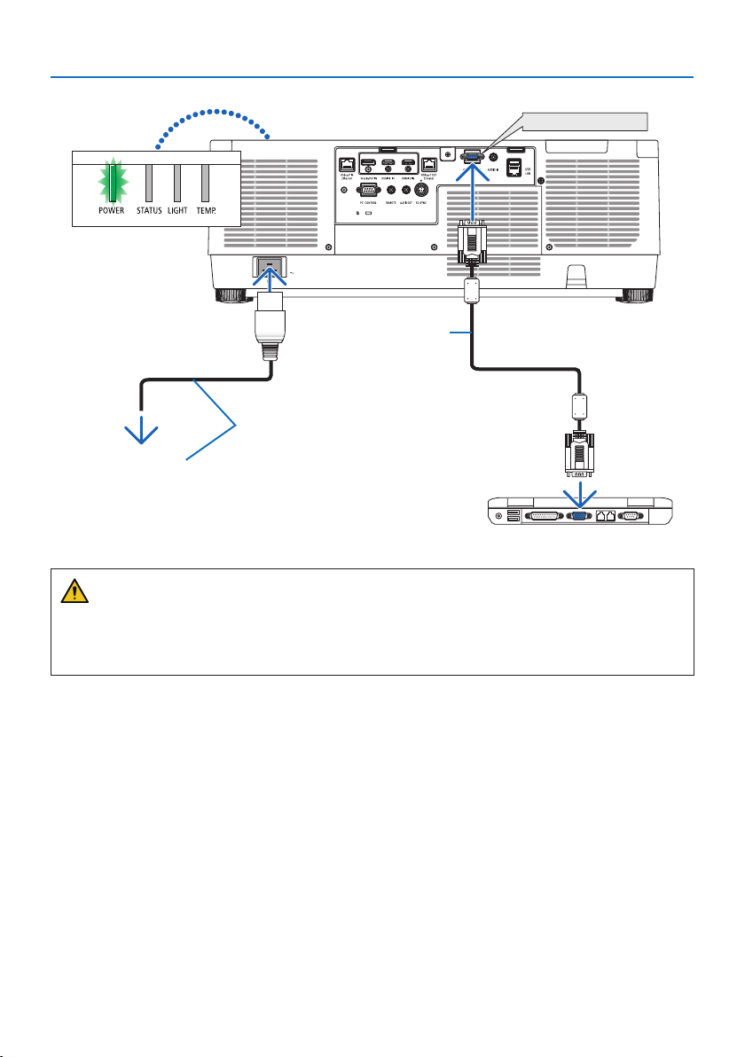
1. Connect your computer to the projector.
This section will show you a basic connection to a computer. For information about other con-
nections, see “6. Connecting to Other Equipment” on page
159.
Connect the display output terminal (mini D-sub 15 pin) on the computer to the computer video
input terminal on the projector with a commercially-available computer cable (with ferrite core)
and then turn the knobs of the connectors to secure them.
2. Connect the supplied power cord to the projector.
First connect the supplied power cord’s three-pin plug to the AC IN terminal of the projector,
and then connect another plug of the supplied power cord directly in the wall outlet. Do not
use any plug converter.
CAUTION:
•Thisequipmentisdesignedtobeusedintheconditionofthepowercordconnectedto
earth. If the power cord is not connected to the earth, it may cause electric shock. Please
make sure the power cord is earthed properly.
Do not use a 2-core plug converter adapter.
•Topreventthepowercordfromcomingloose,makesurethatalltheprongsofthepower
cord plug are fully inserted into the AC IN terminal of the projector before using the power
cord stopper. A loose contact of the power cord may cause a fire or electric shock.
Upon connecting the power cable, the POWER indicator of the projector will light. (→ page
191)
2. Projecting an Image (Basic Operation)
18
COMPUTER IN
Make sure that the prongs are fully inserted
into both the AC IN and the wall outlet.
Computer cable (VGA)
(supplied)
To wall outlet
CAUTION:
Parts of the projector may become temporarily heated if the projector is turned off with the
POWER button or if the AC power supply is disconnected during normal projector operation.
Use caution when picking up the projector.
2. Projecting an Image (Basic Operation)
19
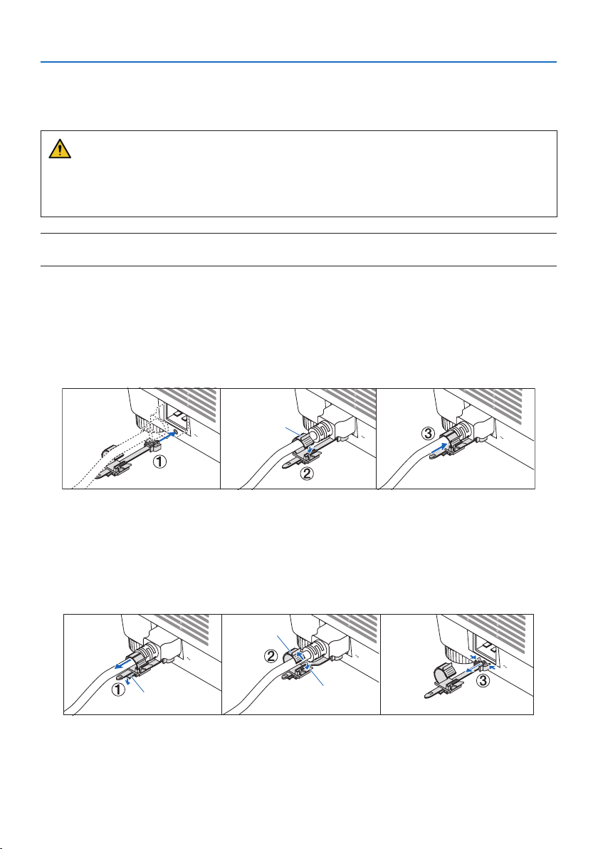
Using the power cord stopper
To prevent the power cord from accidently removing from the AC IN of the projector, use the power
cord stopper.
CAUTION:
To prevent the power cord from coming loose, make sure that all the prongs of the power cord
are fully inserted into the AC IN terminal of the projector before using the power cord stopper
to fix the power cord. A loose contact of the power cord may cause a fire or electric shock.
NOTE:
•Ifyoupullonthepowersupplycordwhiletheconnectorisxed,themainunitmayfalldownandbedamaged
Installing the power cord stopper
① With the clamper facing the power supply cord, align the tip of the power supply cord stopper
with the hole below the AC IN terminal and push it in.
② Pass the power supply cord through the clamper and press the clamper to fix it.
③ Slide the clamper until the base of the power plug.
Clamper
Disconnecting the power cord
① Pull to an appropriate position while pushing down the knob of the power cord stopper.
② Press down the knob on the clamper to open the clamper and take out the power cord.
③ Push and pull the fitted part of the power cord stopper from the left and right to remove it from
the main unit.
Clamper
Knob
Knob
2. Projecting an Image (Basic Operation)
20
2-3. Turning on the Projector
WARNING
The projector produces a strong light. When turning on the power, make sure no one within the
projection range is looking at the lens.
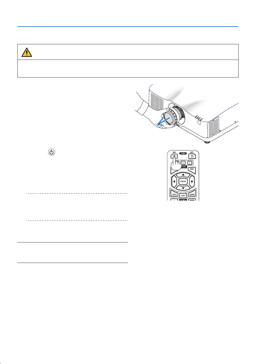
1. Remove the lens cap.
2. Press the (POWER) button on the projec-
tor cabinet or the POWER ON button on the
remote control.
The POWER indicator lit in green will start
to blink in blue. After that, the image will be
projected onto the screen.
TIP:
•Whenthemessage“PROJECTORISLOCKED!ENTERYOUR
PASSWORD.”isdisplayed,itmeansthatthe[SECURITY]
featureisturnedon.(→ page 50)
After you turn on your projector, ensure that
the computer or video source is turned on.
NOTE:
•Abluescreen(bluebackground)isdisplayedwhennosignalis
beinginput(byfactorydefaultmenusettings).
2. Projecting an Image (Basic Operation)
21
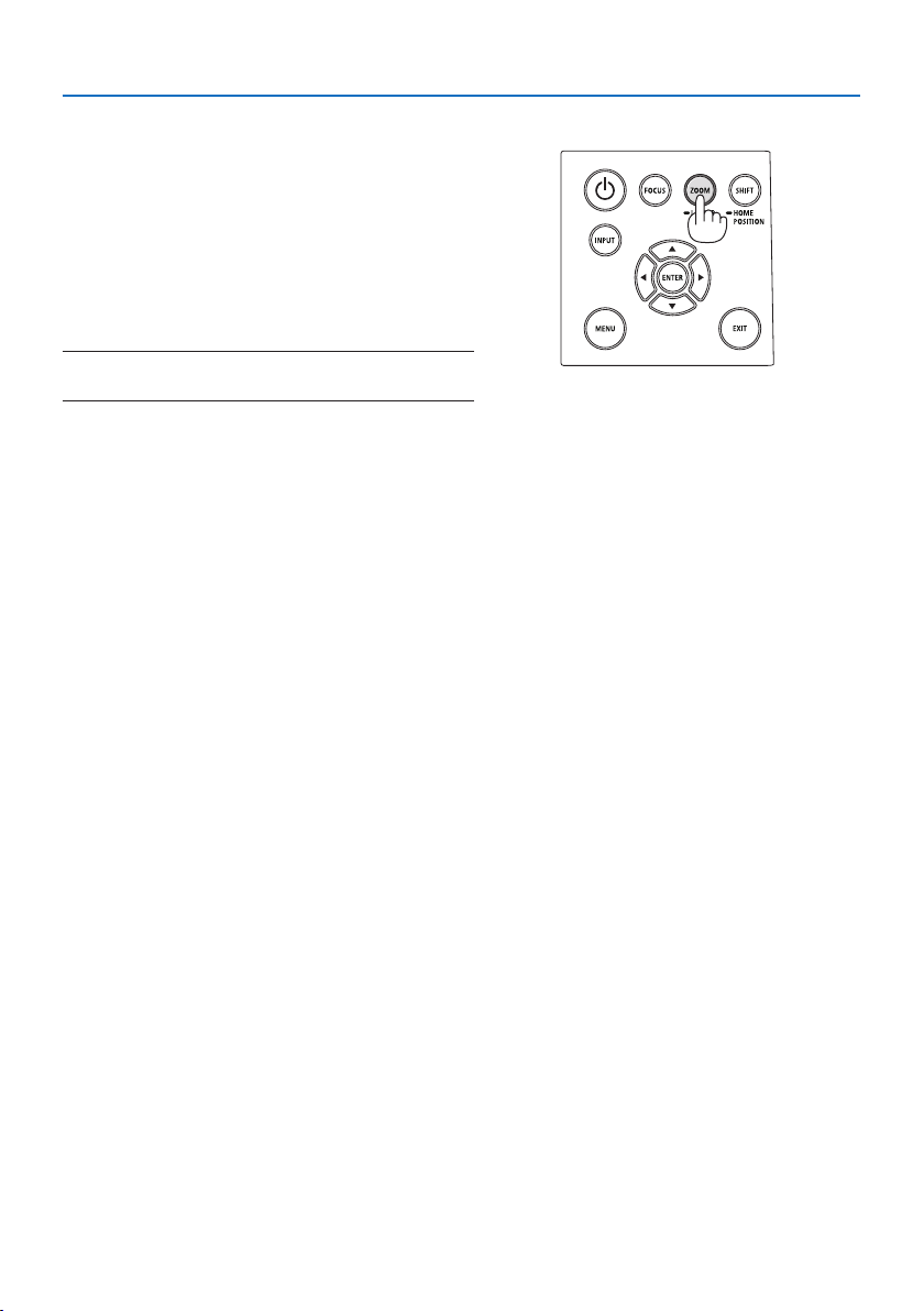
Performing Lens Calibration
After mounting the separately available lens unit or
replacing a lens unit, perform [LENS CALIBRATION]
by holding to press ZOOM/L-CALIB. button on the
cabinet over two seconds.
Calibration corrects the adjustable zoom, shift, and
focus range. If calibration is not performed, you may
not be able to get the best focus and zoom even if
you adjust the focus and zoom for the lens.
NOTE:
•[LENSCALIBRATION]isnotavailableforthelensunitNP44ML.
2. Projecting an Image (Basic Operation)
22
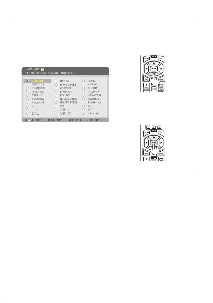
Note on Startup screen (Menu Language Select screen)
When you first turn on the projector, you will get the Startup menu. This menu gives you the op-
portunity to select one of the 30 menu languages.
To select a menu language, follow these steps:
1. Use the ▲, ▼, ◀ or ▶ button to select one of
the 30 languages from the menu.
2. Press the ENTER button to execute the selec-
tion.
After this has been done, you can proceed to
the menu operation.
If you want, you can select the menu language
later.
(→ [LANGUAGE] on page
86 and 123)
NOTE:
•Ifthemessage,[PLEASESET"DATEANDTIME".]isshown,pleasesetthecurrentdateandtime.(→ page 137)
•Inthecasethismessageisnotshown,the[DATEANDTIMESETTINGS]isrecommendedtocomplete.
•Keepthelenscapothelenswhiletheprojector’spowerison.
Ifthelenscapison,itcouldbewarpedduetohightemperature.
•IftheSTATUSindicatorlightsorangewiththepowerbuttonpressed,theprojectorwillnotbeturnedonsincethe[CONTROLPANEL
LOCK]hasbeen[ON].Cancelthelockbyturningito.(→ page 137)
•WhilethePOWERindicatorisblinkingblueinshortcycles,thepowercannotbeturnedobyusingthepowerbutton.
2. Projecting an Image (Basic Operation)
23
2-4. Selecting a Source
Selecting the computer or video source
NOTE:
•Turnonthecomputerorvideosourceequipmentconnectedtotheprojector.
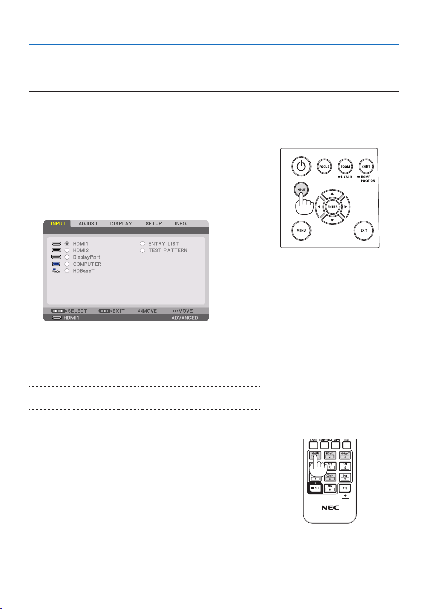
Detecting the Signal Automatically
Press the INPUT button for 1 second or longer. The projector
will search for the available input source and display it. The
inputsourcewillchangeasfollows:
HDMI1 → HDMI2 → DisplayPort → COMPUTER → HDBaseT
→ HDMI1 → …
•Pressitbrieytodisplaythe[INPUT] screen.
•Pressthe▼/▲ buttons to match the target input terminal
and then press the ENTER button to switch the input. To
delete the menu display in the [INPUT] screen, press the
MENU or EXIT button.
TIP:
•Ifnoinputsignalispresent,theinputwillbeskipped.
Using the Remote Control
Press any one of the HDMI1, HDMI2, HDBaseT, DP1 or COMP.
button.
2. Projecting an Image (Basic Operation)
24
Selecting Default Source
You can set a source as the default source so that it will be displayed each time the projector is
turned on.
1. Press the MENU button.
The menu will be displayed.
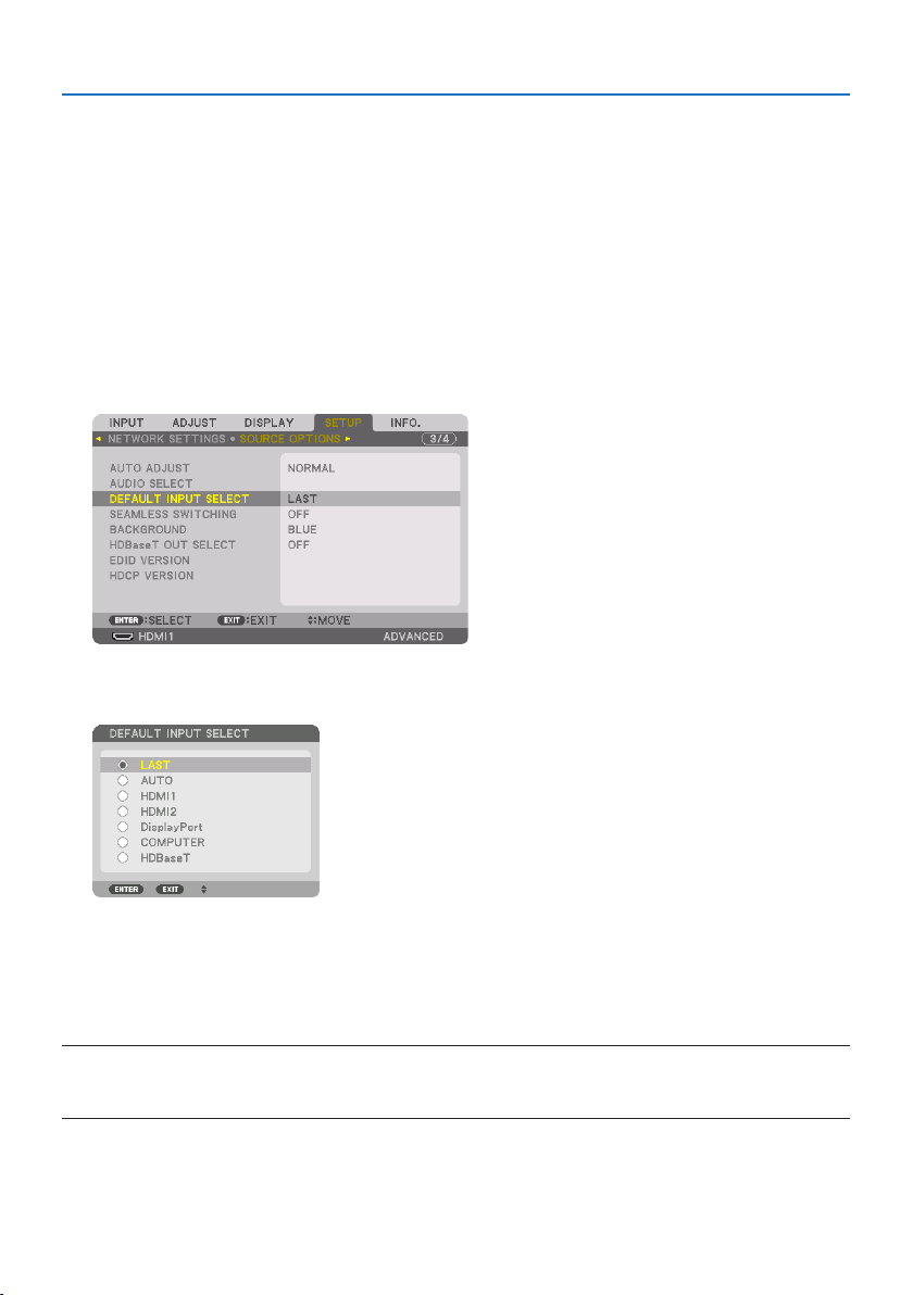
2. Press the ▶buttontoselect[SETUP] and press the ▼ button or the ENTER button to select
[MENU(1)].
3. Press the ▶buttontoselect[SOURCE OPTIONS] and press the ▼ button or the ENTER
button.
4. Press the ▼buttonthreetimestoselect[DEFAULT INPUT SELECT] and press the ENTER
button.
The [DEFAULT INPUT SELECT] screen will be displayed.
(→ page
150)
5. Select a source as the default source, and press the ENTER button.
6. Press the EXIT button a few times to close the menu.
7. Restart the projector.
The source you selected in step 5 will be projected.
NOTE:
•Evenwhen[AUTO]isturnedon,the[HDBaseT]willnotbeautomaticallyselected.Tosetyournetworkasthedefaultsource,select
[HDBaseT].

2. Projecting an Image (Basic Operation)
25
TIP:
•WhentheprojectorisinStandbymode,applyingacomputersignalfromacomputerconnectedtotheCOMPUTERIN input will
powerontheprojectorandsimultaneouslyprojectthecomputer’simage.([AUTOPOWERONSELECT] → page 154)
•OntheWindows10keyboard,acombinationoftheWindowsandPkeysallowsyoutosetupexternaldisplayeasilyandquickly.
2. Projecting an Image (Basic Operation)
26
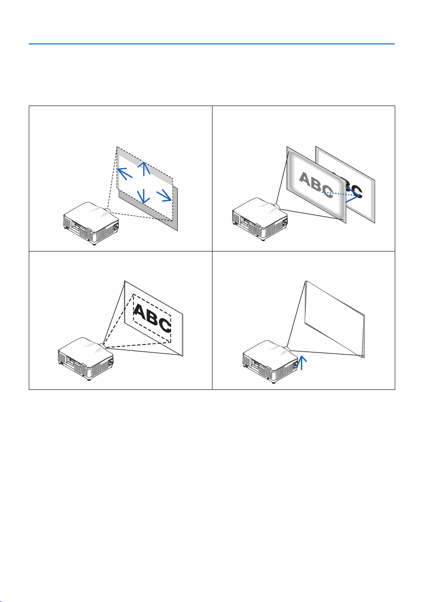
2-5. Adjusting the Picture Size and Position
Use the lens shift, the adjustable tilt foot, the zoom and the focus to adjust the picture size and
position.
In this chapter drawings and cables are omitted for clarity.
Adjusting the projected image’s vertical and
horizontal position
“Lens shift” (→ page 27)
Adjusting the focus
“Focus” (→ page 29)
Finely adjusting the size of an image
“Zoom” (→ page 34)
Adjusting the projected image’s inclination
“Tilt foot” (→ page 35)
2. Projecting an Image (Basic Operation)
27
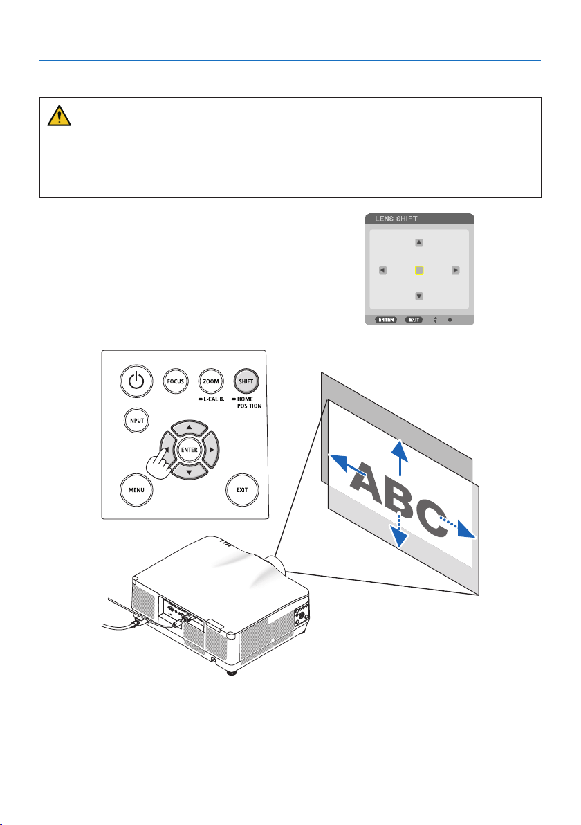
Adjusting the vertical position of a projected image (Lens shift)
CAUTION
•Performtheadjustmentfrombehindorfromthesideoftheprojector.Ifadjustmentsare
performed from the front, your eyes could be exposed to strong light and get injured.
•Keephandsawayfromthelensmountingportionwhileperformingalensshift.Failuretodo
so could result in fingers being pinched by the moving lens.
1. Press either SHIFT/HOME POSITION button
on the cabinet or SHIFT button on the remote
control.
The [LENS SHIFT] screen will be displayed.
2. Press the ▼▲◀▶ buttons to move the projected image.
To set back the lens to the home position
Press and hold the SHIFT/HOME POSITION button over 2 seconds. The lens mounted on the projec-
tor goes back to the home position. (roughly to the center position)
2. Projecting an Image (Basic Operation)
28
NOTE:
•Ifthelensisshiftedtothemaximuminthediagonaldirection,thescreenperipheralareawillbedarkorshaded.
•UseNP11FLatthehomeposition.Ifnecessary,ne-adjustthepositionoftheprojectedimageusingthelensshiftfunction.
•TheNP44MLmustbexedtotheprojectorusingtheseparatelysoldsupportkit(NP02LK).Loosenthescrewsofthesupportbracket,
youcanne-adjustmentofthelensshift.
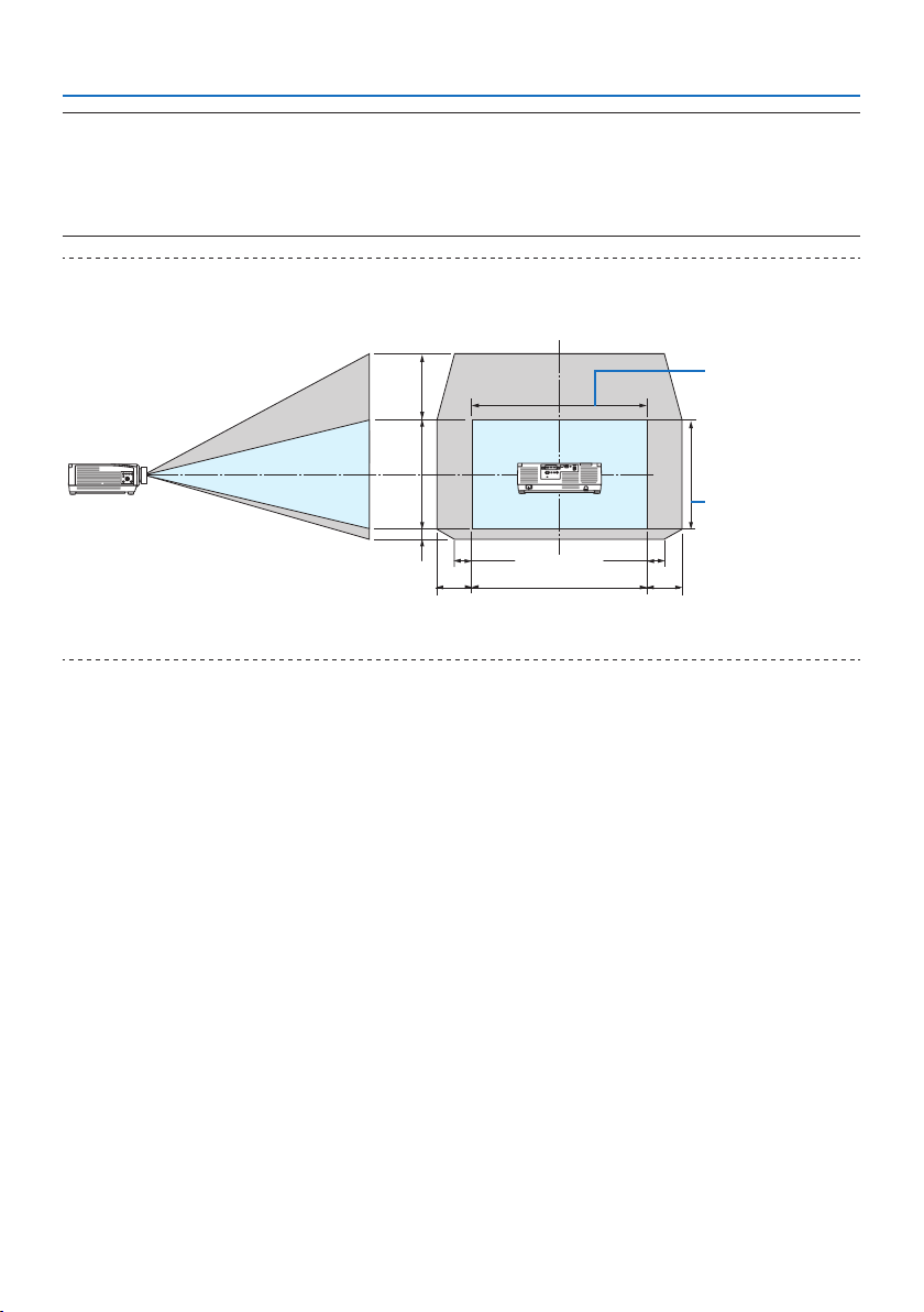
TIP:
•Thegurebelowshowsthelensshiftadjustmentrange(projectionmethod:Desktop/Front)oftheNP41ZLlensunit.Seepage175
forotherlensunits.
Height of projected
image
Width of projected
image
20%H 20%H
50%V
10%V
100%V
10%H10%H
100%H
Descriptionofsymbols:Vindicatesvertical(heightoftheprojectedimage),Hindicateshorizontal(widthoftheprojectedimage).
2. Projecting an Image (Basic Operation)
29
Focus
Recommend to perform the focus adjustment after leaving the projector under the state the TEST
PATTERN has been projected for over 30 minutes.
Please refer to page
92 in the User’s Manual about the TEST PATTERN.
Applicable lens: NP12ZL/NP13ZL/NP14ZL/NP15ZL (Manual focus)
Use the focus ring to obtain the best focus.
Focus ring
2. Projecting an Image (Basic Operation)
30
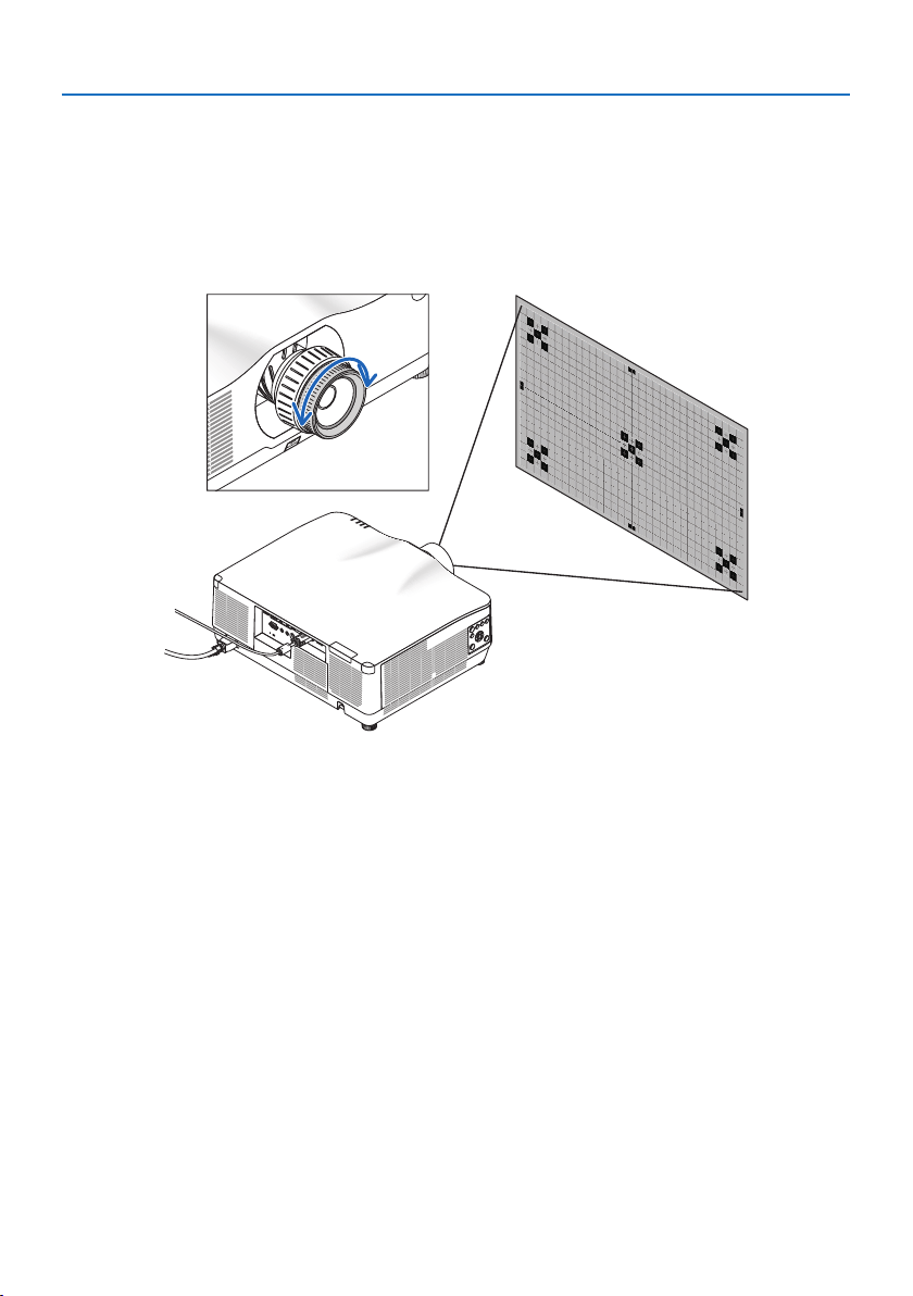
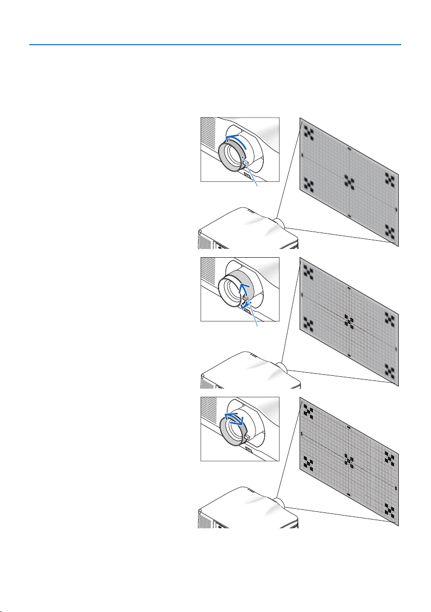
Applicable lens: NP11FL (Manual focus)
With the NP11FL lens, adjust the focus and picture distortion.
Preparations:
Press and hold the SHIFT/HOME POSITION button on the cabinet longer than 2 seconds for shifting
back the lens to the home position.
1. Turn the distortion ring to the left
edge.
Distortion ring
2. Turn the focus lever clockwise and
counterclockwise to adjust the focus
at the center of the screen.
Focus lever
3. Use the distortion ring to correct the
screen’s distortion.
(This also brings the screen peripheral
area into focus.)
4. Use the focus lever to adjust the
screen’s overall focus.
* If the focus at the center of the
screen is off, turn the distortion ring
a little counterclockwise. The focus
at the center of the screen can now
be adjusted with the focus lever.
2. Projecting an Image (Basic Operation)
31
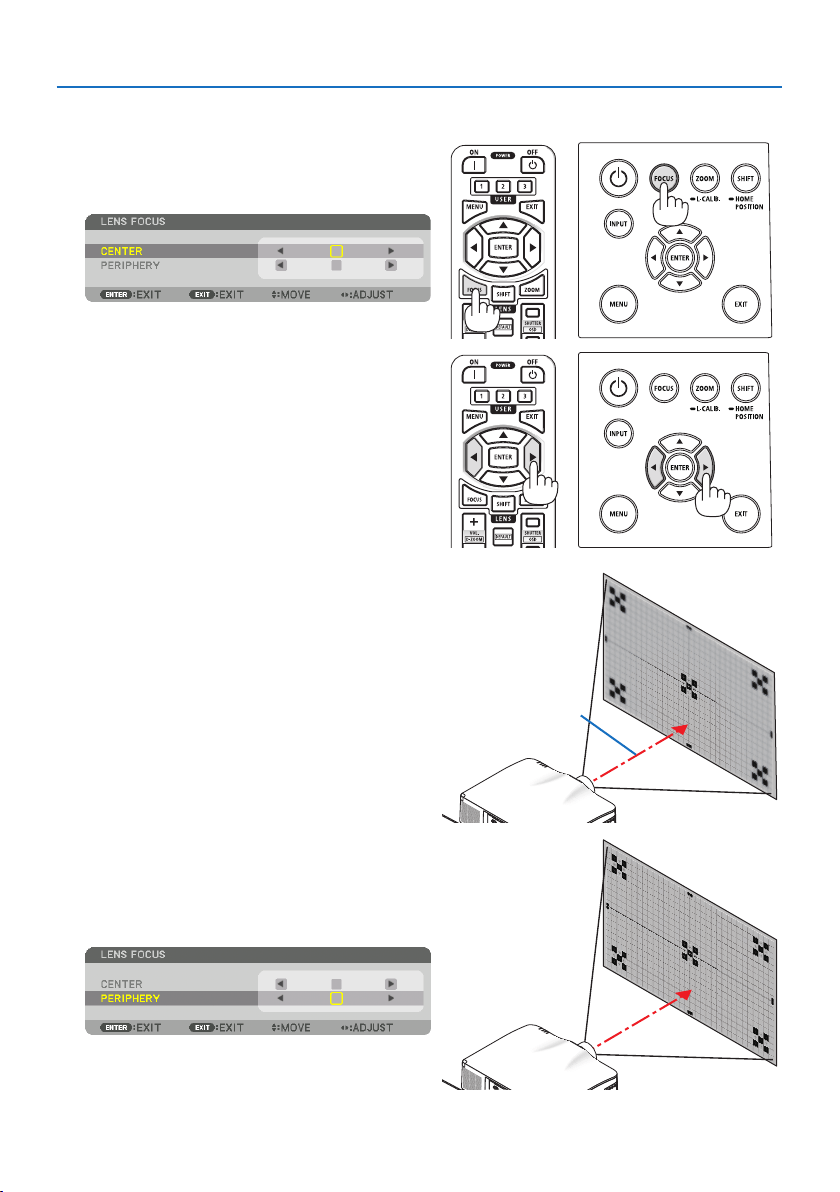
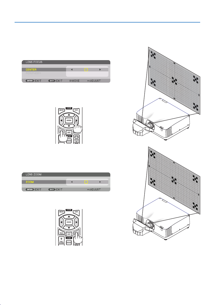
Applicable lens: NP40ZL/NP41ZL (Motorized focus)
1. Press the FOCUS button.
The [LENS FOCUS] control screen will be dis-
played on.
Press ◀▶ buttons to adjust focus.
2. Whenthecursorisonthe[CENTER] on on-
screen menu, press either ◀ or ▶ button to
align focus around the optical axis.
* The picture shows and example when the
lens shift is moved upward. The focus for the
lower part of the screen is aligned.
When the lens is at the center, the focus for
the center of the screen is aligned.
Optical axis
3. Press ▼buttontoselectthe[PERIPHERY] on
the on-screen menu, and then press either ◀
or ▶ button to align the focus of screen pe-
ripheral area. During this operation, the focus
for around the optical axis will be maintained.
2. Projecting an Image (Basic Operation)
32
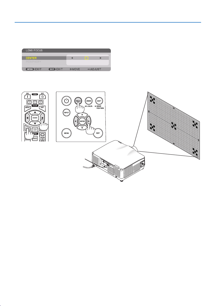
Applicable lens: NP43ZL (Motorized focus)
1. Press the FOCUS button.
The [LENS FOCUS] control screen will be displayed on.
Press ◀▶ buttons to adjust focus.
* [PERIPHERY] LENS FOCUS is not available for this lens unit.
2. Projecting an Image (Basic Operation)
33
Applicable lens: NP44ML (Motorized focus)
•TheNP44MLmustbexedtotheprojectorusingtheseparatelysoldsupportkit(NP02LK).
The support kit is not shown on this illustration.
1. Press the FOCUS button.
The [LENS FOCUS] control screen will be displayed on.
Press ◀▶ buttons to adjust focus of screen center.
* [PERIPHERY] LENS FOCUS is not available for this
lens unit.
2. Press the ZOOM/L-CALIB. button on the cabinet.
The [LENS ZOOM] control screen will be displayed on.
* In another way, press the ZOOM button on the
remote control.
Press ◀▶ buttons to align the focus of screen periph-
eral area.
2. Projecting an Image (Basic Operation)
34
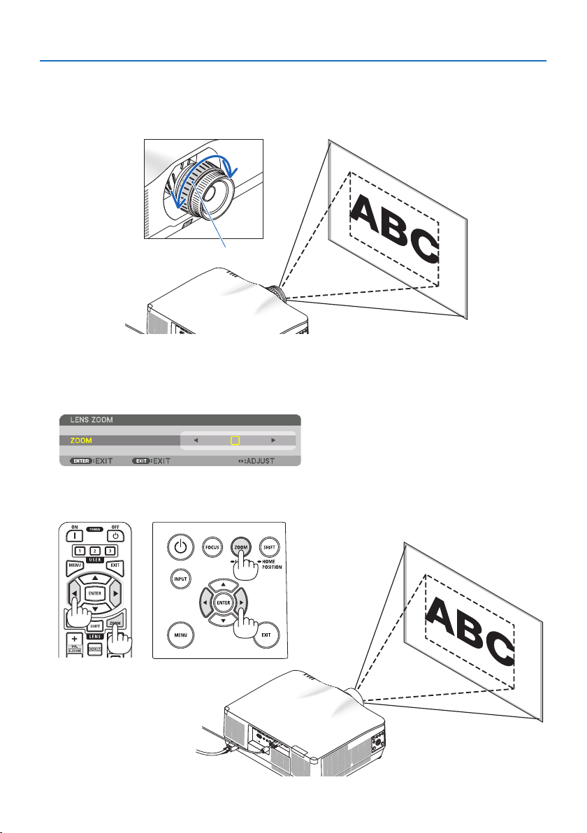
Zoom
Applicable lens: NP12ZL/NP13ZL/NP14ZL/NP15ZL (Manual zoom)
Turn the zoom ring clockwise and counterclockwise.
Zoom ring
Applicable lens: NP40ZL/NP41ZL/NP43ZL (Motorized zoom)
1. Press ZOOM/L-CALIB. button.
The [ZOOM] adjustment screen will be displayed on.
* In another way, press the ZOOM button on the remote control.
Press ◀▶ buttons to adjust zoom.
2. Projecting an Image (Basic Operation)
35
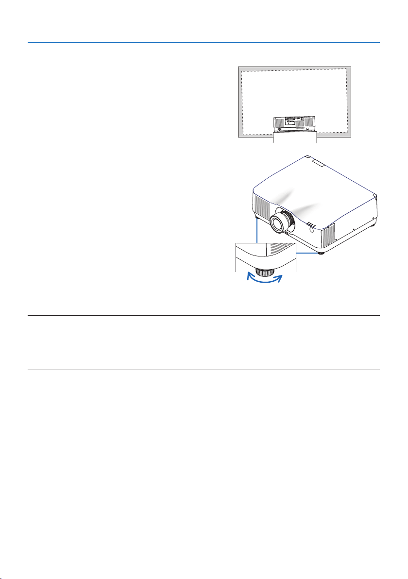
Adjusting the Tilt Foot
1. Turn the left and right tilt foot to adjust.
The tilt foot lengthen and shorten when turned.
Turn one of the tilt foot to adjust the image so
that it is level.
•Iftheprojectedimageisdistorted,see“3-5
Correcting Horizontal and Vertical Keystone
Distortion [CORNERSTONE]” (→ page
45)
and “[GEOMETRIC CORRECTION]” (→ page
113).
•Thetiltfootcanbelengthenedbyamaxi-
mum of 10 mm/0.4".
•Thetiltfootcanbeusedtotilttheprojector
by a maximum of 1.4°.
Up Down
Tilt foot
NOTE:
•Donotlengthenthetiltfootanymorethan10mm/0.4".Doingsowillmaketheprojectorunstable.
•Donotusethetiltfootforanypurposeotherthanadjustinginclinationoftheprojectorinstallationangle.
Handlingthetiltfootimproperly,suchascarryingtheprojectorbygraspingthetiltfootorhookingitontoawallusingthetilt
foot,coulddamagetheprojector.
2. Projecting an Image (Basic Operation)
36
2-6. Adjusting a picture and sound
Adjusting the picture
Display the on-screen menu and adjust the picture. (→ page
96)
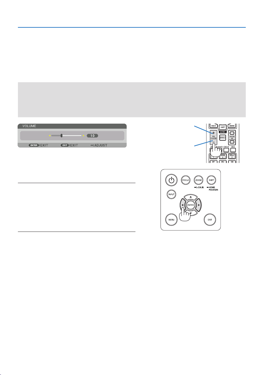
Turning Up or Down Volume
Sound level from the AUDIO OUT terminal can be adjusted.
Important:
•DonotturnupthevolumetothemaximumlevelontheexternalspeakersystemconnectedtotheAUDIOOUToftheprojector.
Doingsomayproduceanunexpected,loudsoundatthetimeofturningonorotheprojector,causingdamagetoyourhearing.
Whenadjustingthevolumeontheexternalspeakersystem,setvolumelevelofthespeakersystemtolessthanhalfitsratingand
adjustthevolumeontheprojectortogetappropriatesoundlevel.
When no menus appear, the ◀ and ▶ buttons on
the projector cabinet work as a volume control.
•Ontheremotecontrol,presstheVOL./D-ZOOM
(+) or (−)button.
NOTE:
•Thevolumecannotbeadjustedusingthe◀ or ▶buttoninthe
followingcases.
•Whentheon-screenmenuisdisplayed
•WhenthescreenisenlargedbypressingtheVOL./D-ZOOM (+)
(−)buttonswhileholdingdowntheCTLbuttonontheremote
control
X
Increase volume
Decrease volume
2. Projecting an Image (Basic Operation)
37
2-7. Turning off the Projector
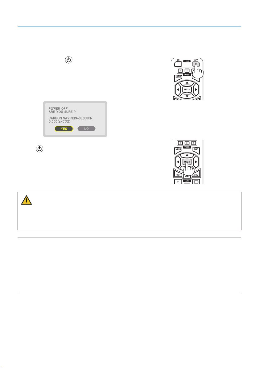
Toturnotheprojector:
1. First, press the
(POWER) button on the
projector cabinet or the POWER OFF button
on the remote control.
The [POWER OFF / ARE YOU SURE ? / CARBON
SAVINGS-SESSION 0.000[g-CO2]] message will
appear.
2. Secondly, press the ENTER button or press
the (POWER) or the POWER OFF button
again.
The light source will be turned off and the power
supply will be cut.
CAUTION
•Partsoftheprojectormaybecometemporarilyheatediftheprojectoristurnedowiththe
POWER button or if the AC power supply is disconnected during normal projector operation.
Use caution when picking up the projector.
NOTE:
•WhilethePOWERindicatorisblinkingblueinshortcycles,thepowercannotbeturnedo.
•Youcannotturnothepowerfor60secondsimmediatelyafterturningitonanddisplayinganimage.
•Donotunplugthepowercordfromtheprojectororfromthepoweroutletwhileanimageisbeingprojected.Doingsocould
deterioratetheprojector’sACINterminalorthepowerplug’scontact.ToturnotheACpowerwhileanimageisbeingprojected,
usethepowerstrip’sswitch,thebreaker,etc.
•DonotdisconnecttheACpowersupplytotheprojectorwithin10secondsofmakingadjustmentorsettingchangesandclosing
themenu.Doingsocancauselossofadjustmentsandsettings.

2. Projecting an Image (Basic Operation)
38
2-8. After Use
1. Unplug the power cord.
2. Disconnect any other cables.
3. Mount the lens cap on the lens.
4. Before moving the projector, screw in the tilt foot if they have been lengthened.
39
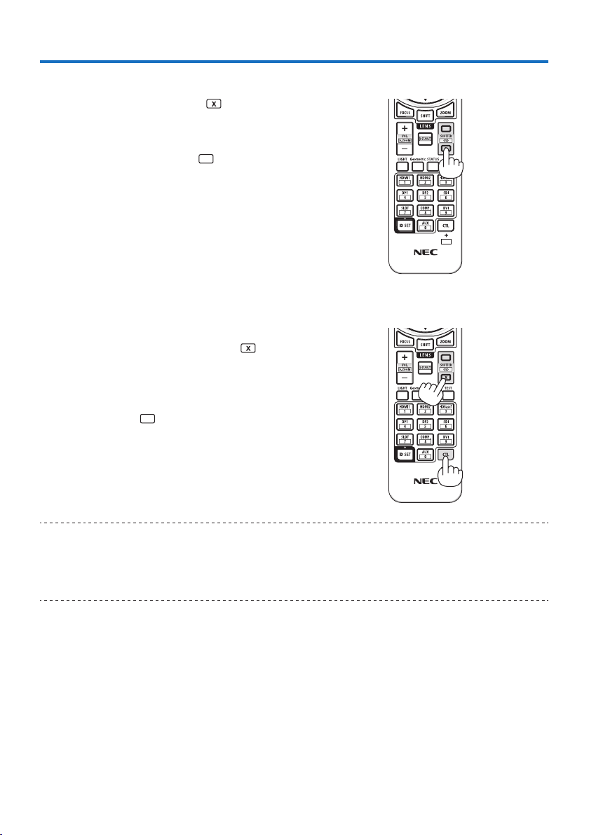
3-1. Turn off the light of the projector (LENS SHUTTER)
1. Press the SHUTTER CLOSE (
) button on the
remote control.
The light source will turn off temporarily.
Press the SHUTTER OPEN (
) button to allow
the screen to become illuminated again.
•Youcansettheprojectionlighttogradually
fade in or out.
3-2. Turning Off the On-Screen Menu (On-Screen Mute)
1. Hold down the CTL button on the remote
control and press the OSD CLOSE (
) button.
The on-screen menu, input terminal, etc. will
disappear.
•Todisplaytheon-screendisplay,pressthe
OSD OPEN (
) button while holding down
the CTL button on the remote control.
TIP:
•Toconrmthattheon-screenmuteisturnedon,presstheMENUbutton.Iftheon-screenmenuisnotdisplayedeventhoughyou
press the MENUbutton,itmeanstheon-screenmuteisturnedon.
•Theon-screenmuteismaintainedevenwhentheprojectoristurnedo,
•HoldingdowntheMENUbuttonontheprojectorcabinetforatleast10secondswillturnotheon-screenmute.
3. Convenient Features
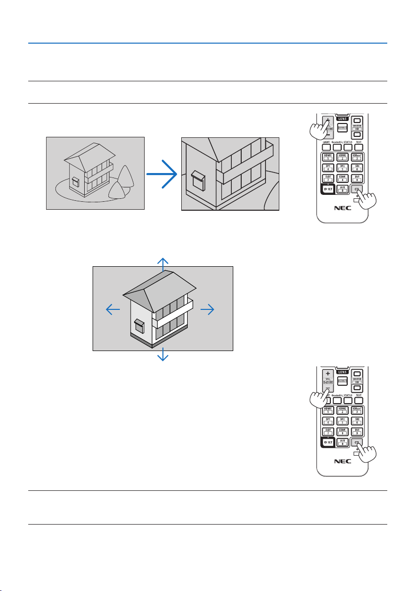
3. Convenient Features
40
3-3. Enlarging a Picture
You can enlarge the picture up to four times.
NOTE:
•Dependingonaninputsignal,themaximummagnicationmaybelessthanfourtimes,orthefunctionmayberestricted.
1. Press and hold the CTL button and then press VOL./D-ZOOM (+)
button on the remote control to magnify the picture.
X
2. Press the ▲▼◀▶ button.
The area of the magnified image will be moved
3. Press and hold the CTL button and then press VOL./D-ZOOM (−)
button on the remote control.
Each time the button is pressed, the image is reduced.
X
NOTE:
•Theimagewillbeenlargedorreducedatthecenterofthescreen.
•Displayingthemenuwillcancelthecurrentmagnication.
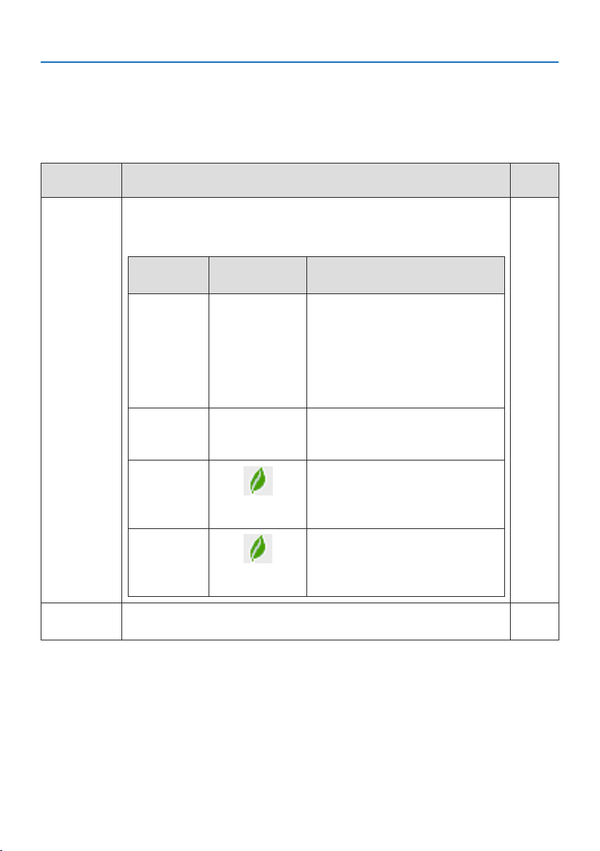
3. Convenient Features
41
3-4. Adjustment of luminance (brightness) and energy-saving effect
Youcanadjusttheoutputoftheunittoarangeof50–100%(inincrementsof1%)andcontrolthe
brightness after adjustment to keep it constant. Also, set the [REF. LIGHT MODE] to [ECO1] or [ECO2]
to reduce the brightness and operating sound. By saving energy consumption, the CO
2
emission
from this projector can be reduced. There are two ways to set the light mode.
Function
name
Description Page
REF.LIGHTMODETheadjustmentvaluesofthe[REF.LIGHTMODE]andbrightnessaresavedasasettingcommon
toallinputsignals.
Validwhenthe[MODE] (→ page
96)issetto[STANDARD].
REF.LIGHTMODE
Iconatthebottomof
the menu
Description
BOOSTThepicturebecomesbrighterthanthe
[NORMAL]mode.However,theoperatingnoise
andpowerconsumptionwillalsoincreasedue
tocontrolofthecoolingfanaccordingtothe
brightness.Thelifeoftheopticalcomponents
mayalsobeshorteneddependingonthe
operatingenvironment.
NORMAL100%brightness
Alternatively,youcanadjusttheoutputfrom
50to100%using[REF.LIGHTADJUST].
ECO1
Brightnesswillbeatabout80%.
Thecoolingfanwillalsoslowdownaccord-
ingly.
Lower power consumption
ECO2
Brightnesswillbeatabout50%.
Thecoolingfanwillalsoslowdownaccord-
ingly.
Lowerpowerconsumptionconsiderably
128
LIGHTMODEAdjustthebrightnessandsaveitforeachinputsignal.
Validwhenthe[MODE] (→ page 96)issetto[PROFESSIONAL].
99
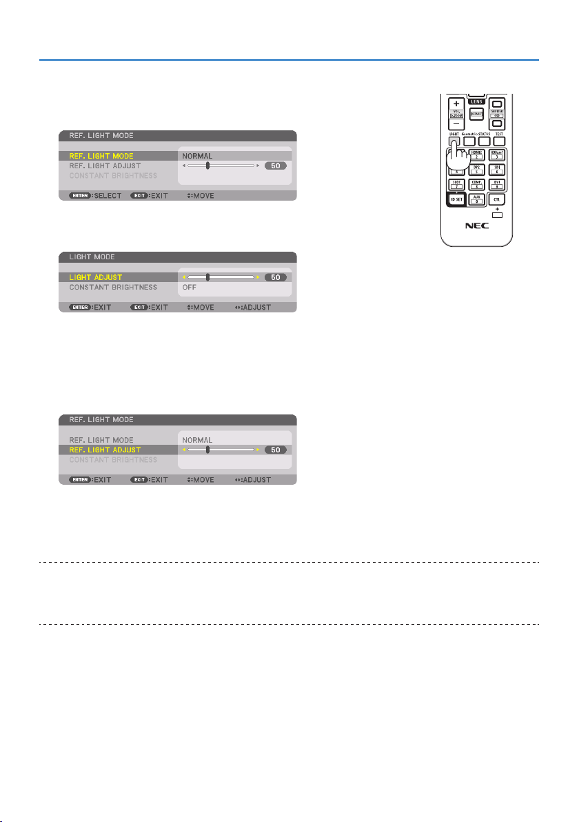
3. Convenient Features
42
Display the [LIGHT MODE] screen
1. Press LIGHT button on the remote control.
When[STANDARD]isselectedfor[MODE]
The [REF. LIGHT MODE] screen will be displayed.
When[PROFESSIONAL]isselectedfor[MODE]
The [LIGHT MODE] screen will be displayed.
X
Perform [LIGHT ADJUST]
An explanation is given here using the [REF. LIGHT MODE] screen.
1. Press the ▼buttontoadjustthecursorto[REF. LIGHT ADJUST].
2. Press the ◀▶ button to adjust.
To keep the brightness after adjustment constant, set [CONSTANT BRIGHTNESS] to [ON].
Press the MENU button to cancel the menu screen.
TIP:
•Brightnessnormallydecreaseswithuse,butbyselecting[CONSTANTBRIGHTNESS]mode,sensorsinsidetheprojectordetect
brightnessandautomaticallyadjusttheoutput,therebymaintainingaconstantbrightnessthroughoutthelifeofthelightmodule.
However,ifoutputisalreadyatitsmaximum,brightnesswilldecreasewithuse.
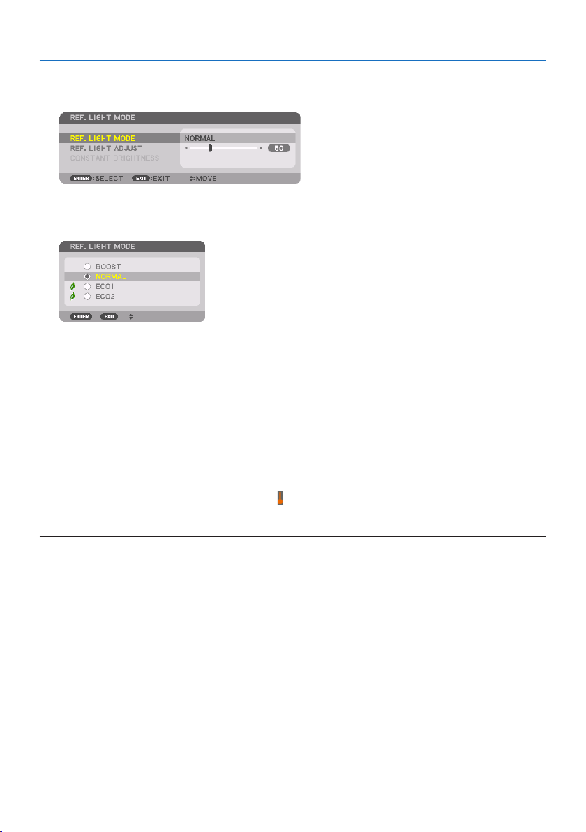
3. Convenient Features
43
Change [REF. LIGHT MODE]
1. Withthecursoradjustedto[REF. LIGHT MODE], press the ENTER button.
The [REF. LIGHT MODE] selection screen will be displayed.
2. Use the ▼▲ buttons to make a selection, and press the ENTER button.
The display will return to the [REF. LIGHT MODE] screen and the selected option will be applied.
Press the MENU button to return to the original screen.
NOTE:
•Thelightmodulehoursusedcanbecheckedin[USAGETIME]onthemenu.Select[INFO.] →[USAGETIME].
•Afteralapseof1minutefromwhentheprojectordisplaysablue,blackorlogoscreen,[REF.LIGHTMODE]willautomaticallyswitch
to[ECO].
•Theluminance(brightness)maydecreasetemporarilydependingonthetemperatureoftheoperatingenvironmentandthe[REF.
LIGHTMODE]setting.
Thisisoneoftheprotectionfunctionscalled“ForcedECOMODE”.When“ForcedECOMODE”isinoperation,theTEMP.Indicatorlights
upinorange.Atthesametime,theThermometersymbol[]isdisplayedatthelowerrightofthemenuscreen.Thetemperature
insidetheprojectordecreasesduetotheroomtemperaturebeinglowered,cancellingthe“ForcedECOMODE”andreturningtothe
originalbrightness.
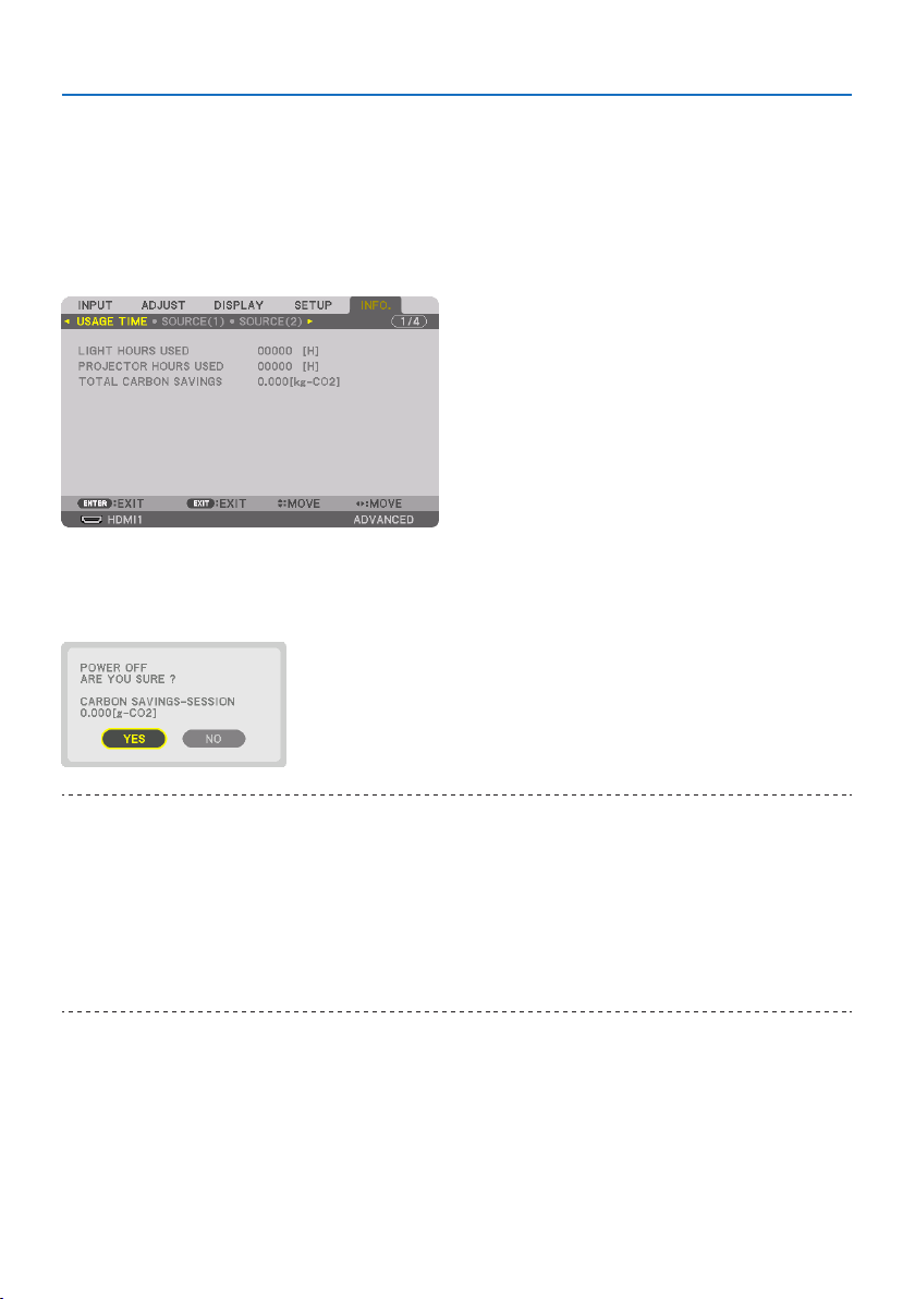
3. Convenient Features
44
Checking Energy-Saving Effect [CARBON METER]
This feature will show energy-saving effect in terms of CO
2
emission reduction (kg) when the pro-
jector’s [LIGHT MODE] is set to either [ECO1] or [ECO2]. This feature is called as [CARBON METER].
Therearetwomessages:[TOTAL CARBON SAVINGS] and [CARBON SAVINGS-SESSION]. The [TOTAL
CARBON SAVINGS] message shows the total amount of CO
2
emission reduction from the time of
shipment up to now. You can check the information on [USAGE TIME] from [INFO.] of the menu.
(→ page
156)
The [CARBON SAVINGS-SESSION] message shows the amount of CO
2
emission reduction between
the time of changing to [LIGHT MODE] immediately after the time of power-on and the time of
power-off. The [CARBON SAVINGS-SESSION] message will be displayed in the [POWER OFF / ARE
YOU SURE ?] message at the time of power-off.
TIP:
•TheformulashownbelowisusedtocalculatetheamountofCO
2
emissionreduction.AmountofCO
2
emissionreduction=(Power
consumptionin[NORMAL][REF.LIGHTMODE]–Powerconsumptionincurrentsetting)×CO
2
conversionfactor.*Whenanenergy-
saving[LIGHTMODE]isselected,ortheLensShutterisused,therewillbeafurtherreductioninCO
2
emission.
*CalculationforamountofCO
2
emissionreductionisbasedonanOECDpublication“CO
2
EmissionsfromFuelCombustion,2008
Edition”.
•The[TOTALCARBONSAVINGS]iscalculatedbasedonsavingsrecordedin15minutesintervals.
•ThepowerconsumptionwhentheprojectorisinstandbymodeisexcludedfromthecalculationoftheamountofCO
2
emission
reduction.
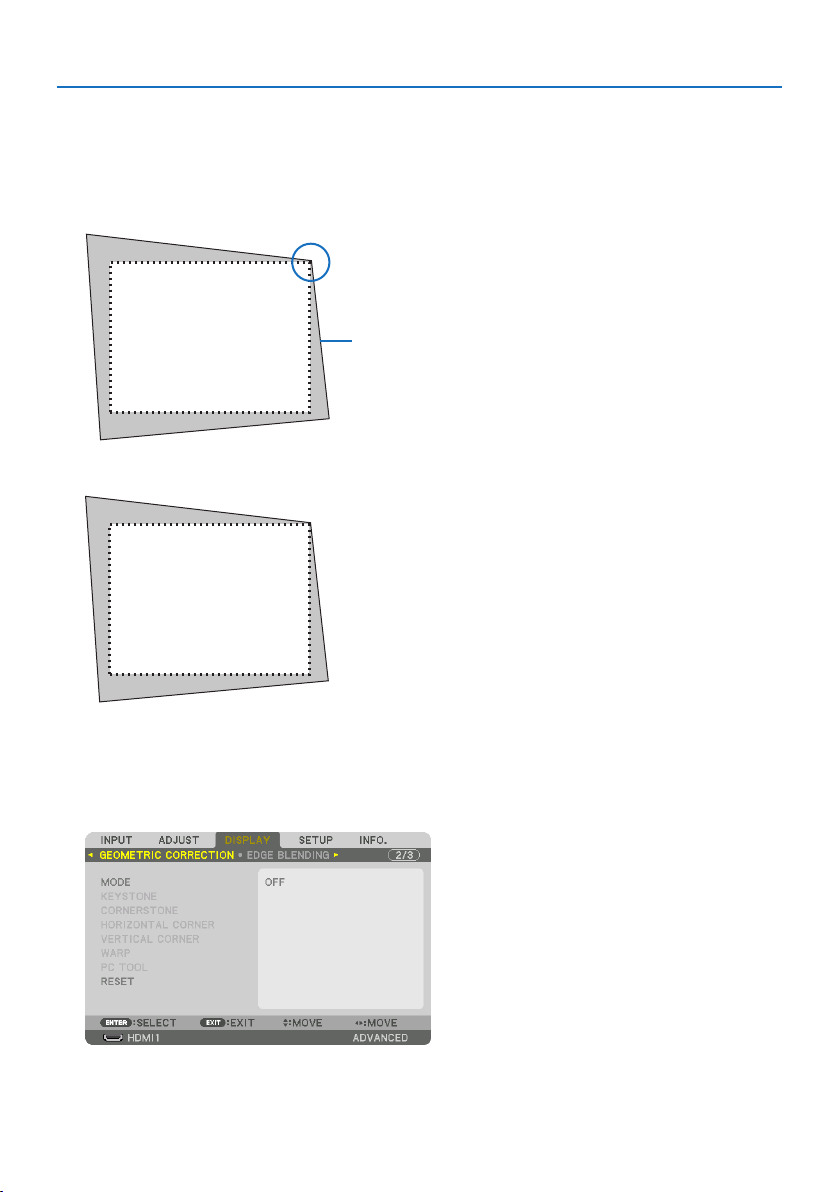
3. Convenient Features
45
3-5. Correcting Horizontal and Vertical Keystone Distortion
[CORNERSTONE]
Use the [CORNERSTONE] feature to correct keystone (trapezoidal) distortion to make the top or bot-
tom and the left or right side of the screen longer or shorter so that the projected image is rectangular.
1. Project an image so that the screen is smaller than the area of the raster.
Projected image
The drawing shows the upper right corner.
2. Pick up any one of the corners and align the corner of the image with a corner of the screen.
3. Press the Geometric. button either on the cabinet or the remote control.
Display the [GEOMETRIC CORRECTION] screen of the on-screen menu.
4. Movethecursoronto[MODE] by ▼ button and press the ENTER.
The mode selection screen will displayed on.
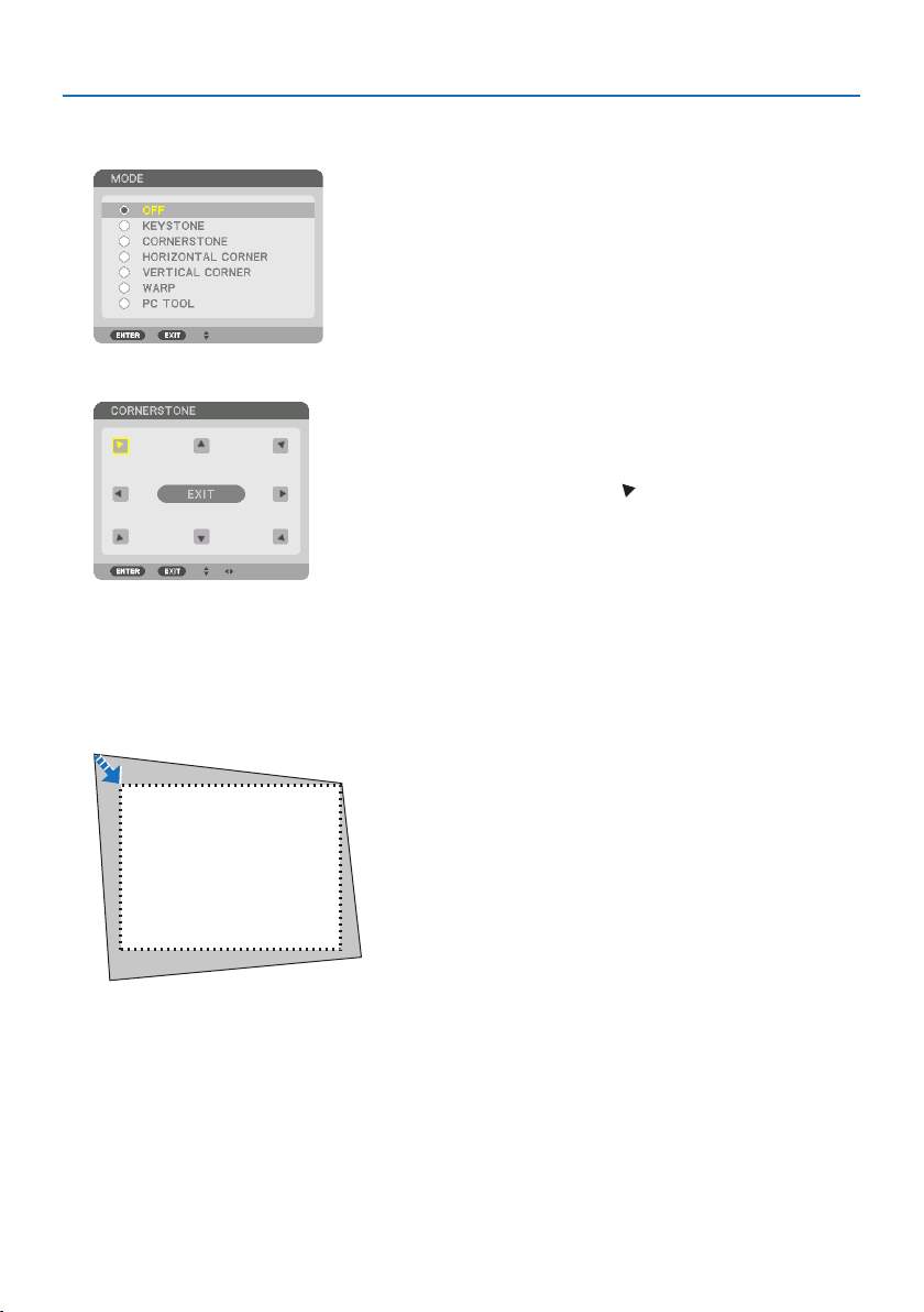
3. Convenient Features
46
5. Select[CORNERSTONE] and press the ENTER.
Go back to display the [GEOMETRIC CORRECTION] screen of the on-screen menu.
6. Press the ▼buttontoalignwiththe[CORNERSTONE] and then press the ENTER button.
The drawing shows the upper left icon ( ) is selected.
The screen will switch to the [CORNERSTONE] screen.
7. Use the ▲▼◀▶ button to select one icon (▲) which points in the direction you wish to
move the projected image frame.
8. Press the ENTER button.
9. Use the ▲▼◀▶ button to move the projected image frame as shown on the example.
10. Press the ENTER button.
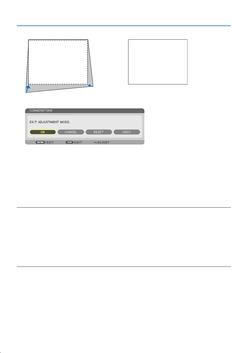
3. Convenient Features
47
11. Use the ▲▼◀▶ button to select another icon which points in the direction.
On the [CORNERSTONE] screen, select [EXIT] or press the EXIT button on the remote control.
The confirmation screen is displayed.
12. Press the ◀ or ▶buttontohighlightthe[OK] and press the ENTER button.
This completes the [CORNERSTONE] correction.
•Select[CANCEL] and press the ENTER button to return to the [CORNERSTONE] screen.
Selecting [CANCEL] will return to the adjustment screen without saving changes (Step 3).
Selecting [RESET] will return to the factory default.
Selecting [UNDO] will exit without saving changes.
NOTE:
•Evenwhentheprojectoristurnedon,thelastusedcorrectionvaluesareapplied.
•Carryouteitheroneofthefollowingactionstocleartheadjustmentvalueof[CORNERSTONE].
-InStep11,select[RESET]andthenpresstheENTERbutton.
-Inthestate[CORNERSTONE]hasbeenselectedfor[MODE]inthe[GEOMETRICCORRECTION]:
*PresstheGeometric.buttonfor2ormoreseconds.
*Run[DISPLAY] →[GEOMETRICCORRECTION] →[RESET]intheon-screenmenu.
•Using[CORNERSTONE]correctioncancausetheimagetobeslightlyblurredbecausethecorrectionismadeelectronically.
•AcommerciallyavailableUSBmouseisavailablefor[CORNERSTONE]correction.
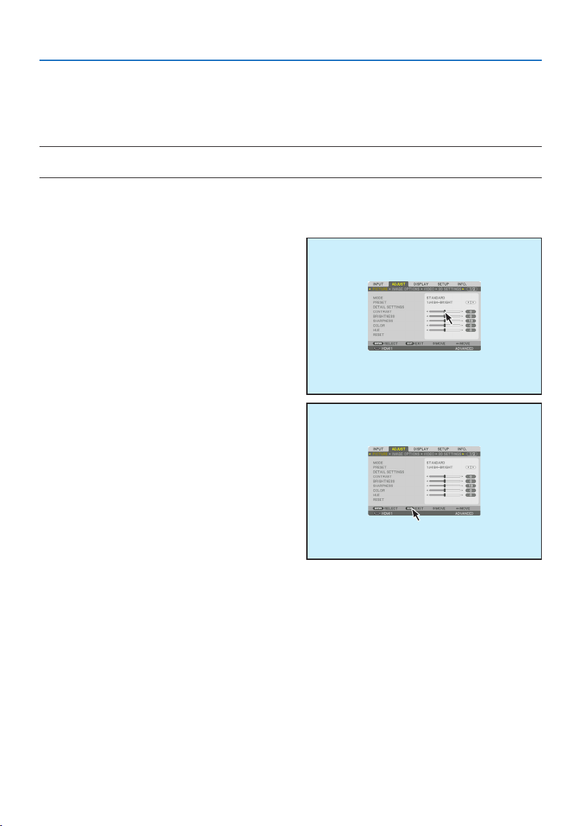
3. Convenient Features
48
3-6. Operation for the On-Screen Menu by a commercially available USB
mouse
Once a commercially available USB mouse is connected to this projector, it enables to perform the
operation for the on-screen menu and the geometric correction easily.
NOTE:
•NotguaranteetheperformanceofallUSBmouseavailableonthemarket.
Menu operation
1. Display the on-screen menu by right click.
2. Select a desired menu and perform adjust-
ment by left click.
The adjustment bar can be control by drag
and drop.
3.Select[EXIT] displayed at the bottom of
the menu by left click for going back to the
previous level. If the cursor is on the main
menu option, it works for closing the menu.
(It works as the same performance with the
EXIT button on the remote control.)
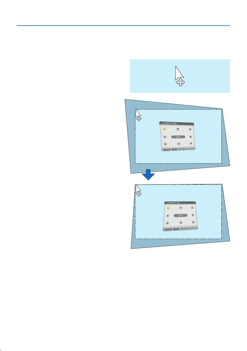
3. Convenient Features
49
Geometric correction
The USB mouse can be used for [CORNERSTONE] CORRECTION, [HORIZONTAL CORNER], [VERTI-
CAL CORNER], and [WARP]. In this clause, the [CORNERSTONE] CORRECTION by an USB mouse is
explained as an example.
1.Whiletheadjustmentscreenofthe[COR-
NERSTONE] CORRECTION is displayed,
right click on the projection screen. The
shape of mouse pointer will be changed
and the correction will become avail-
able.
2. Left click at the screen corner. The pro-
jection screen corner will move to the
mouse clicked position.
3. Repeat the step 2 for correcting all dis-
tortion. After completion of distortion
correction, right click on the projection
screen. The shape of mouse pointer will
be changed to normal.
4. Leftclick[EXIT] on the correction screen
to finish.
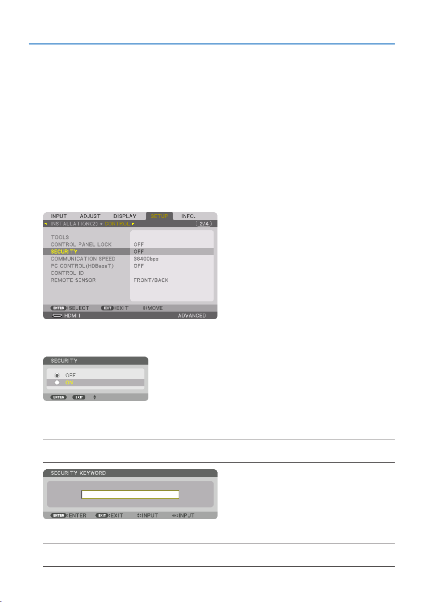
3. Convenient Features
50
3-7. Preventing the Unauthorized Use of the Projector [SECURITY]
A keyword can be set for your projector using the Menu to avoid operation by an unauthorized
user. When a keyword is set, turning on the projector will display the Keyword input screen. Unless
the correct keyword is entered, the projector cannot project an image.
•The[SECURITY] setting cannot be cancelled by using the [RESET] of the menu.
To enable the Security function:
1. Press the MENU button.
The menu will be displayed.
2. Press the ▶buttontwicetoselect[SETUP] and press the ▼ button or the ENTER button
toselect[MENU(1)].
3. Press the ▶buttontoselect[CONTROL].
4. Press the ▼buttonthreetimestoselect[SECURITY] and press the ENTER button.
The [OFF]/[ON] menu will be displayed.
5. Press the ▼buttontoselect[ON] and press the ENTER button.
The [SECURITY KEYWORD] screen will be displayed.
6. Type in a combination of the four ▲▼◀▶ buttons and press the ENTER button.
NOTE:
•Akeywordmustbe4to10digitsinlength.
The [CONFIRM KEYWORD] screen will be displayed.
NOTE:
•Makeanoteofyourpasswordandstoreitinasafeplace.
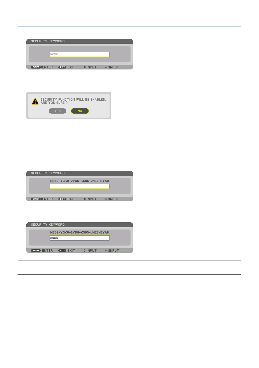
3. Convenient Features
51
7. Type in the same combination of ▲▼◀▶ buttons and press the ENTER button.
The confirmation screen will be displayed.
8. Select[YES] and press the ENTER button.
The [SECURITY] function has been enabled.
To turn on the projector when [SECURITY] is enabled:
1. Press the POWER ON button.
The projector will be turned on and display a message to the effect that the projector is locked.
2. Press the MENU button.
3. Type in the correct keyword and press the ENTER button. The projector will display an
image.
NOTE:
•Thesecuritydisablemodeismaintaineduntilthemainpoweristurnedoorunpluggingthepowercord.
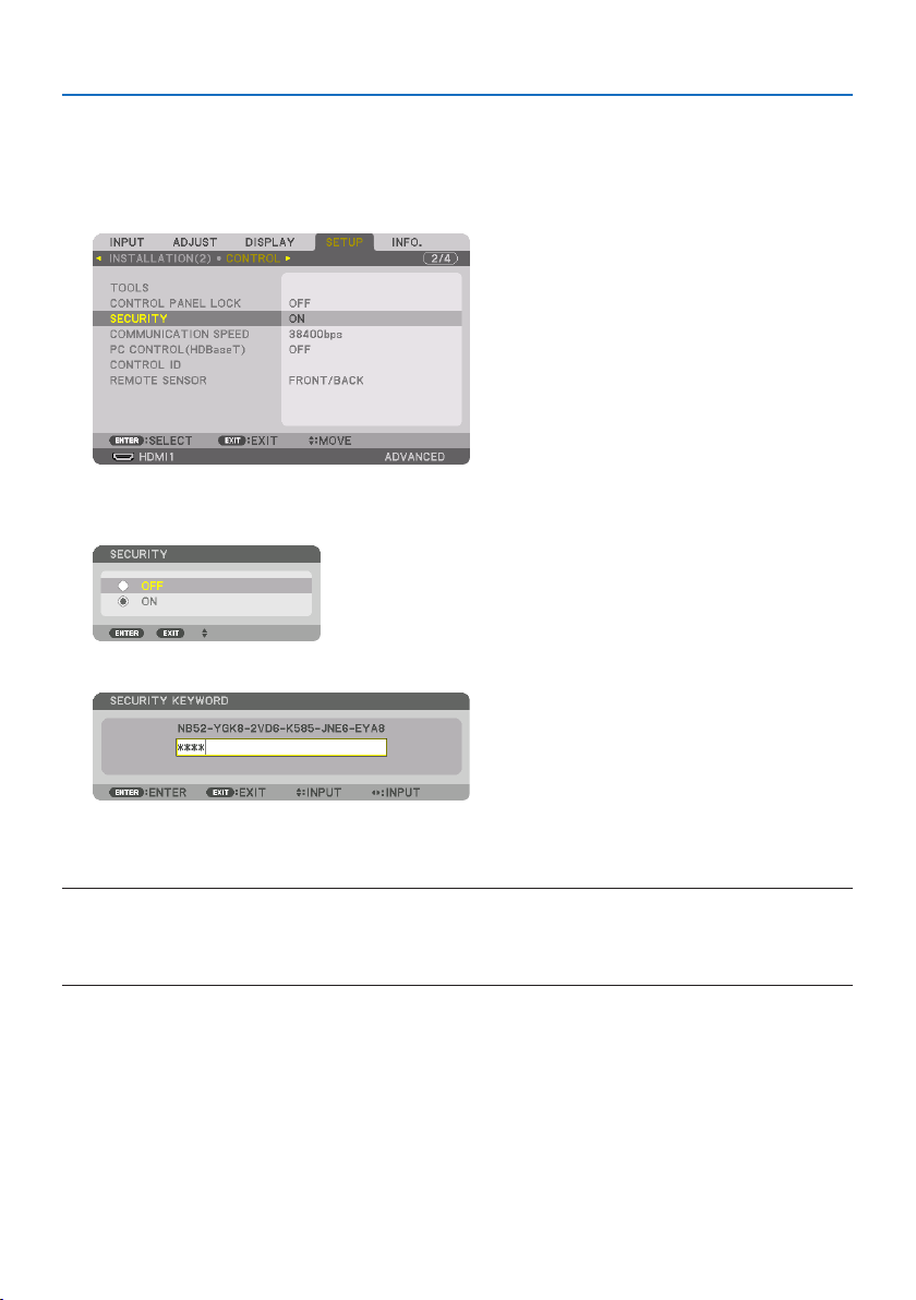
3. Convenient Features
52
To disable the [SECURITY] function:
1. Press the MENU button.
The menu will be displayed.
2.Select[SETUP] →[CONTROL] →[SECURITY] and press the ENTER button.
The [OFF]/[ON] menu will be displayed.
3. Select[OFF] and press the ENTER button.
The [SECURITY KEYWORD] screen will be displayed.
4. Type in your keyword and press the ENTER button.
When the correct keyword is entered, the [SECURITY] function will be disabled.
NOTE:
•Ifyouforgetyourkeyword,contactyourdealer.Yourdealerwillprovideyouwithyourkeywordinexchangeforyourrequestcode.
YourrequestcodeisdisplayedintheKeywordConrmationscreen.Inthisexample[NB52-YGK8-2VD6-K585-JNE6-EYA8]isarequest
code.

3. Convenient Features
53
3-8. Projecting 3D videos
This projector can be used to watch videos in 3D using commercially-available active shutter-type
3D eyewear. In order to synchronize the 3D video and eyewear, a commercially-available 3D emitter
needs to be connected to the projector (on the projector side).
The 3D eyewear receives information from the 3D emitter and performs opening and closing on
the left and right.
CAUTION
Health precautions
Before use, please make sure to read any health precautions that may be stated in the operating
manuals enclosed with the 3D eyewear and 3D video software (Blu-ray player, games, computer
animation files, etc.).
Please take note of the following in order to avoid adverse health effects.
•Pleasedonotusethe3Deyewearforpurposesotherthantowatch3Dvideos.
•Pleasekeepadistanceofatleast2mawayfromthescreenwhenwatchingvideos.Watching
a video too close to the screen will increase eye fatigue.
•Pleasedonotwatchvideoscontinuouslyforalongperiodoftime.Pleasetakea15minutes’
break after every hour of watching.
•Pleaseconsultadoctorbeforewatchingifyouoranyofyourfamilymembershaveahistory
of suffering from seizures caused by light sensitivity.
•Pleasestopwatchingimmediatelyandtakearestwhenyoufeelphysicallyunwellwhilewatch-
ing (vomiting, giddiness, nausea, headaches, sore eyes, blurred vision, cramps and dumbness
in the limbs, etc.). Please consult a doctor if the symptoms persist.
•Pleasewatcha3Dvideodirectlyinfrontofthescreen.Ifyouwatcha3Dvideoobliquelyfrom
the sides, this may result in physical and eye fatigue.
3D eyewear and 3D emitter preparations
Please use an active shutter-type 3D eyewear that conforms with the VESA standard.
A commercially-available RF type made by XPANDVISION is recommended.
3DeyewearXPANDX105-RF
3D emitter XPANDAD025-RF-X1
Procedure to watch 3D videos using this projector
1. Connect the video device to the projector.
2. Switch on the power supply to the projector.
3. Run the 3D video software and project the video using the projector.
This has been automatically set up when shipped from the factory. When a 3D video cannot
be projected, it may be because the 3D detection signals are not included or because they are
not detectable by the projector.
Please manually select the format.
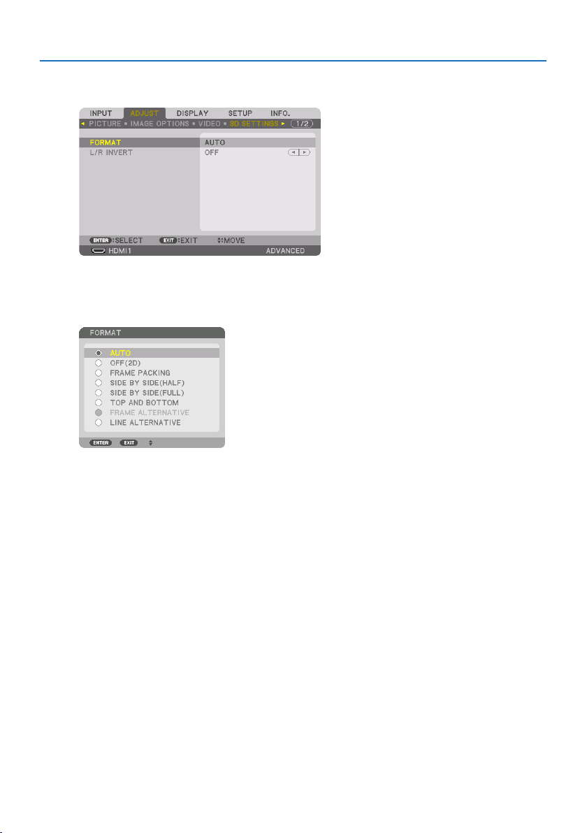
3. Convenient Features
54
4. Select the 3D video format.
(1) Press the MENU button to display the on-screen menu and select [ADJUST] → [3D SETTINGS].
(2) Press the ▼ button to align the cursor with the [FORMAT] and press the ENTER button.
The format screen will be displayed.
(3) Select the input signal format using the ▼ button and then press the ENTER button.
The 3D settings screen will disappear and the 3D video will be projected.
Press the MENU button and the on-screen menu will disappear.
The 3D caution message screen will be displayed when switching to a 3D video (default factory
setting when shipped). Please read the “Health Precautions” on the previous page to watch
videos in the correct manner. The screen will disappear after 60 seconds or when the ENTER
button is pressed. (→ page
124)
5. Turn on the power supply of the 3D eyewear and wear the eyewear to watch the video.
A normal video will be shown when a 2D video is input.
To watch a 3D video in 2D, select [OFF(2D)] in the [FORMAT] screen mentioned above in (3).

3. Convenient Features
55
NOTE:
•Uponswitchingto3Dimage,thefollowingfunctionswillbecancelledanddisabled.[BLANKING],[PIP/PICTUREBYPICTURE],
[GEOMETRICCORRECTION],[EDGEBLENDING](Astheadjustedvaluesof[GEOMETRICCORRECTION]and[EDGEBLENDING] are
maintained,whenyouswitchto2Dpicture,theadjustedscreenwillbedisplayedagain.)
•Theoutputmaynotautomaticallyswitchtoa3Dvideodependingonthe3Dinputsignal.
•ChecktheoperatingconditionsdescribedintheusermanualoftheBlu-rayplayer.
•PleaseconnecttheDINterminalofthe3Demittertothe3DSYNCofthemainprojector.
•The3Deyewearallowsvideostobeviewedin3Dbyreceivingsynchronizedopticalsignalsoutputfromthe3Demitter.
Asaresult,the3Dimagequalitymaybeaectedbyconditionssuchasthebrightnessofthesurroundings,screensize,viewing
distance,etc.
•Whenplayinga3Dvideosoftwareonacomputer,the3DimagequalitymaybeaectedifthecomputerCPUandgraphicschip
performancearelow.Pleasechecktherequiredoperatingenvironmentofthecomputerthatisstatedintheoperatingmanual
attachedtothe3Dvideosoftware.
•Dependingonthesignal,[FORMAT]and[L/RINVERT]maynotbeabletobeselected.Pleasechangethesignalinthatcase.
When videos cannot be viewed in 3D
Please check the following points when videos cannot be viewed in 3D.
Please also read the operating manual attached to the 3D eyewear.
Possible reasons Solutions
The selected signal does not support 3D output. Please change the video signal input to one that
supports 3D.
The format for the selected signal is turned to
[OFF(2D)].
Please change the format in the on-screen menu to
[AUTO] or a format that supports 3D.
A eyewear that is not supported by the projector is
being used.
Please purchase a commercially-available 3D eye-
wear or 3D emitter (recommended). (→ page
53)
Please check the following points when a video
cannot be viewed in 3D using a 3D eyewear that is
supported by the projector.
The power supply of the 3D eyewear is turned
off.
Please turn on the power supply of the 3D eyewear.
The internal battery of the 3D eyewear is flat. Please charge or replace the battery.
The viewer is located too far away from the
screen.
Please get closer to the screen until the video can be
seen in 3D.
Please turn the [L/R INVERT] in the on-screen menu
to [OFF].
Due to multiple 3D projectors working at the
same time in the vicinity, the projectors may in-
terfere with one another. Alternatively, there may
be a bright light source near the screen.
Please maintain sufficient distance between the
projectors.
Please keep the light source away from the screen.
Please turn the [L/R INVERT] in the on-screen menu
to [OFF].
There is an obstacle between the optical receiver of
the 3D eyewear and the 3D emitter.
Please remove the obstacle.
The 3D format of the 3D video contents is not sup-
ported.
Please check with the company selling the 3D video
contents.

3. Convenient Features
56
3-9. Controlling the Projector by Using an HTTP Browser
Overview
You can display the HTTP server screen of the projector by using a web browser and operating the
projector with a computer or smartphone.
Possible operations on the HTTP server screen
•Operatetheprojector.
Operations such power on/off of the projector, input terminal switchover, and lens control etc.
can be carried out.
•Adjustingthepictureandprojectionscreen,suchaspictureadjustment,geometriccorrection,
edge blending, etc. is possible.
•Networksettings(smartphonesarenotsupported)
Configure the various settings when using the projector connected to a network (wired LAN).
Also, it is possible to configure the connection settings with various control systems.
For details about settings and adjustments, see the explanation on the screen menu.
Important:
•Thedefault[WIREDLAN]settingofthisprojectorissetto[DISABLE]whenitisshippedfromthefactory.Toconnecttoanetwork,
displaytheon-screenmenuandchangethe[WIREDLAN]prolesettinginthe[NETWORKSETTINGS]from[DISABLE]to[PROFILE
1]or[PROFILE2]toenablethe[WIREDLAN].
•Whensettingupa[WIREDLAN]forthersttimeafterpurchasingtheunit,besuretosetthe[NETWORKPASSWORD].
To view the HTTP server screen
For computers
1. Connect the projector to the computer with a LAN cable sold commercially. (→ page
168)
2.Select[SETUP] →[NETWORK SETTINGS] →[WIRED LAN] in the on-screen menu to configure
the network settings. (→ page
143)
3. Start up the web browser on your computer and enter the address or URL in the input
field.
SpecifytheaddressorURLas“http://<IPAddressofProjector>/index.html”.
The HTTP server screen will be displayed.
For smartphones
1. Connect a wireless LAN compatible router to the projector with a commercially available
LAN cable.
2.Select[SETUP] →[NETWORK SETTINGS] →[WIRED LAN] in the on-screen menu to configure
the network settings. (→ page
143)
3. Configure the network settings of the smartphone so that it can be connected to the
projector.

3. Convenient Features
57
4. Start up the web browser and enter the address or URL in the input field.
SpecifytheaddressorURLas“http://<IPAddressofProjector>/index.html”.
The HTTP server screen will be displayed.
NOTE:
•Tousetheprojectorinanetwork,consultwithyournetworkadministratoraboutnetworksettings.
•Thedisplay’sorbutton’sresponsecanbesloweddownoroperationmaynotbeaccepteddependingthesettingsofyournetwork.
Shouldthishappen,consultyournetworkadministrator.Theprojectormaynotrespondifitsbuttonsarerepeatedlypressedinrapid
intervals.Shouldthishappen,waitamomentandrepeat.Ifyoustillcan’tgetanyresponse,turnoandbackontheprojector.
•IfthePROJECTORNETWORKSETTINGSscreendoesnotappearinthewebbrowser,presstheCtrl+F5keystorefreshyourweb
browser(orclearthecache).
•Thisprojectoruses“JavaScript”and“Cookies”andthebrowsershouldbesettoacceptthesefunctions.Thesettingmethodwillvary
dependingontheversionofbrowser.Pleaserefertothehelplesandtheotherinformationprovidedinyoursoftware.
Preparation before Use
Connect the projector to a commercially available LAN cable before engaging in browser opera-
tions. (→ page
168)
Operation with a browser that uses a proxy server may not be possible depending on the type of
proxy server and the setting method. Although the type of proxy server will be a factor, it is possible
that items that have actually been set will not be displayed depending on the effectiveness of the
cache, and the contents set from the browser may not be reflected in operation. It is recommended
that a proxy server not be used unless it is unavoidable.
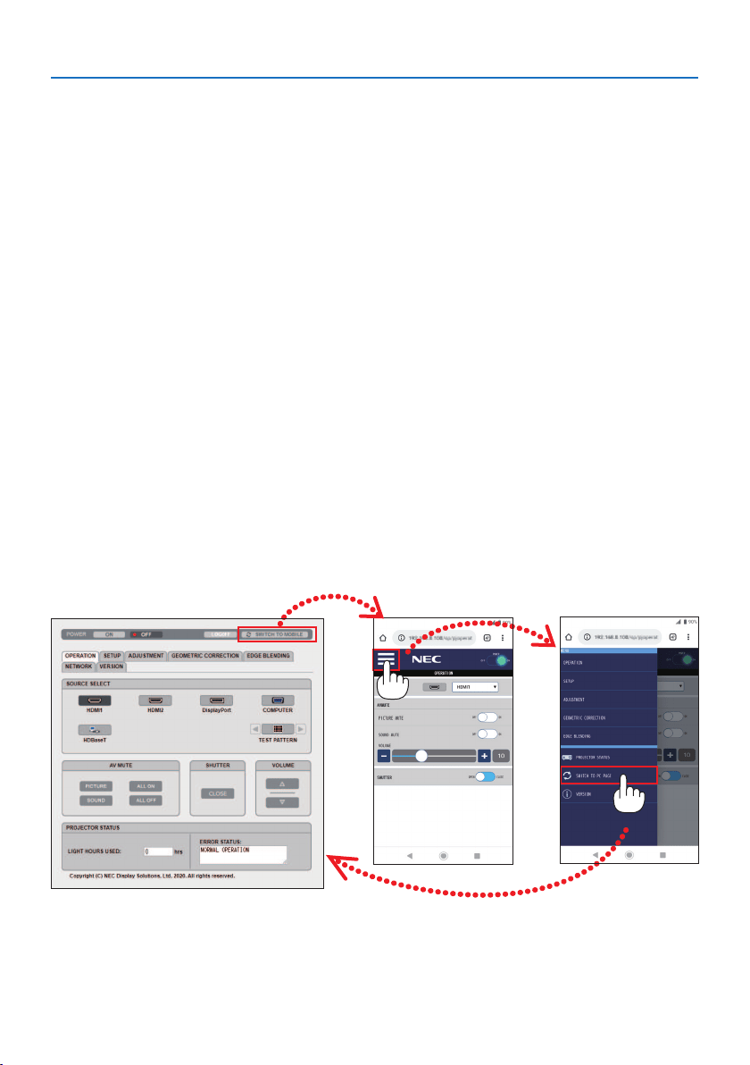
3. Convenient Features
58
Handling of the Address for Operation via a Browser
Regarding the actual address that is entered for the address or entered to the URL column when
operation of the projector is via a browser, the host name can be used as it is when the host name
corresponding to the IP address of the projector has been registered to the domain name server
by a network administrator, or the host name corresponding to the IP address of the projector has
been set in the “HOSTS” file of the computer being used.
Example1:Whenthehostnameoftheprojectorhasbeensetto“pj.nec.co.jp”,accessisgainedto
the network setting by specifying
http://pj.nec.co.jp/index.html
for the address or the entry column of the URL.
Example2:WhentheIPaddressoftheprojectoris“192.168.73.1”,accessisgainedtothenetwork
setting by specifying
http://192.168.73.1/index.html
for the address or the entry column of the URL.
HTTP server screen
The screen size of the terminal being used is automatically determined to display the computer
screen or smartphone screen.
You can also switch between the computer screen and the smartphone screen manually.
•Whenswitchingthedisplayfromacomputertoasmartphone
Press the [SWITCH TO MOBILE] button at the top right of the screen.
•Whenswitchingthedisplayfromasmartphonetoacomputer
Press the menu button at the top left of the screen, and select [SWITCH TO PC PAGE].
Screen for computer Screen for smartphone

3. Convenient Features
59
3-10. Storing Changes for Lens Shift, Zoom, and Focus [LENS MEMORY]
This function serves to store the adjusted values when using the [LENS SHIFT], motorized [ZOOM],
and motorized [FOCUS] functions of the projector. Adjusted values can be applied to the signal
you selected. This will eliminate the need to adjust lens shift, focus, and zoom at the time of source
selection. There are two ways to save adjusted values for lens shift, zoom, and focus.
Function name Description Page
REF.LENSMEMORYAdjustedvaluescommontoallinputsignals.Atthetimeofinstallation,twokindsof
adjustedvaluescanbestored.
Ifnoadjustedvalueshavebeensavedto[LENSMEMORY],thelenswillapply[REF.
LENSMEMORY]adjustedvalues.
130
LENSMEMORYAdjustedvaluesforeachinputsignal.
Usetheadjustedvaluesforthesignalwithadierentaspectratioorresolution.The
adjustedvaluescanbeappliedatthetimeofsourceselection.
108
NOTE:
•Besuretocarryout[LENSCALIBRATION]afterreplacingthelens.
•[LENSMEMORY]and[LENSCALIBRATION]arenotavailableforthelensunitNP44ML.
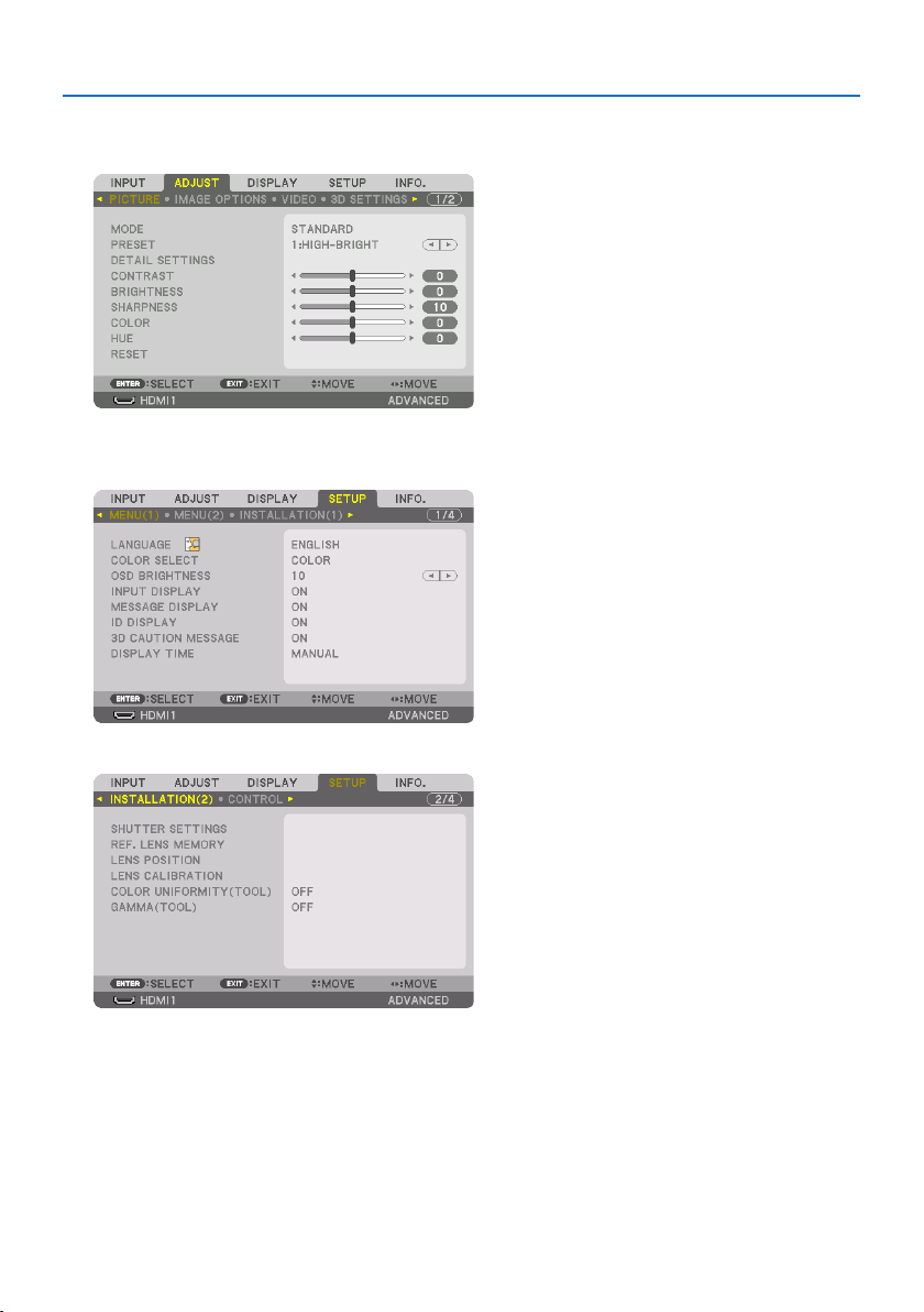
3. Convenient Features
60
To store your adjusted values in [REF. LENS MEMORY]:
1. Press the MENU button.
The menu will be displayed.
2. Press the ▶buttontoselect[SETUP] and press the ENTER button.
3. Press the ▶buttontoselect[INSTALLATION(2)].
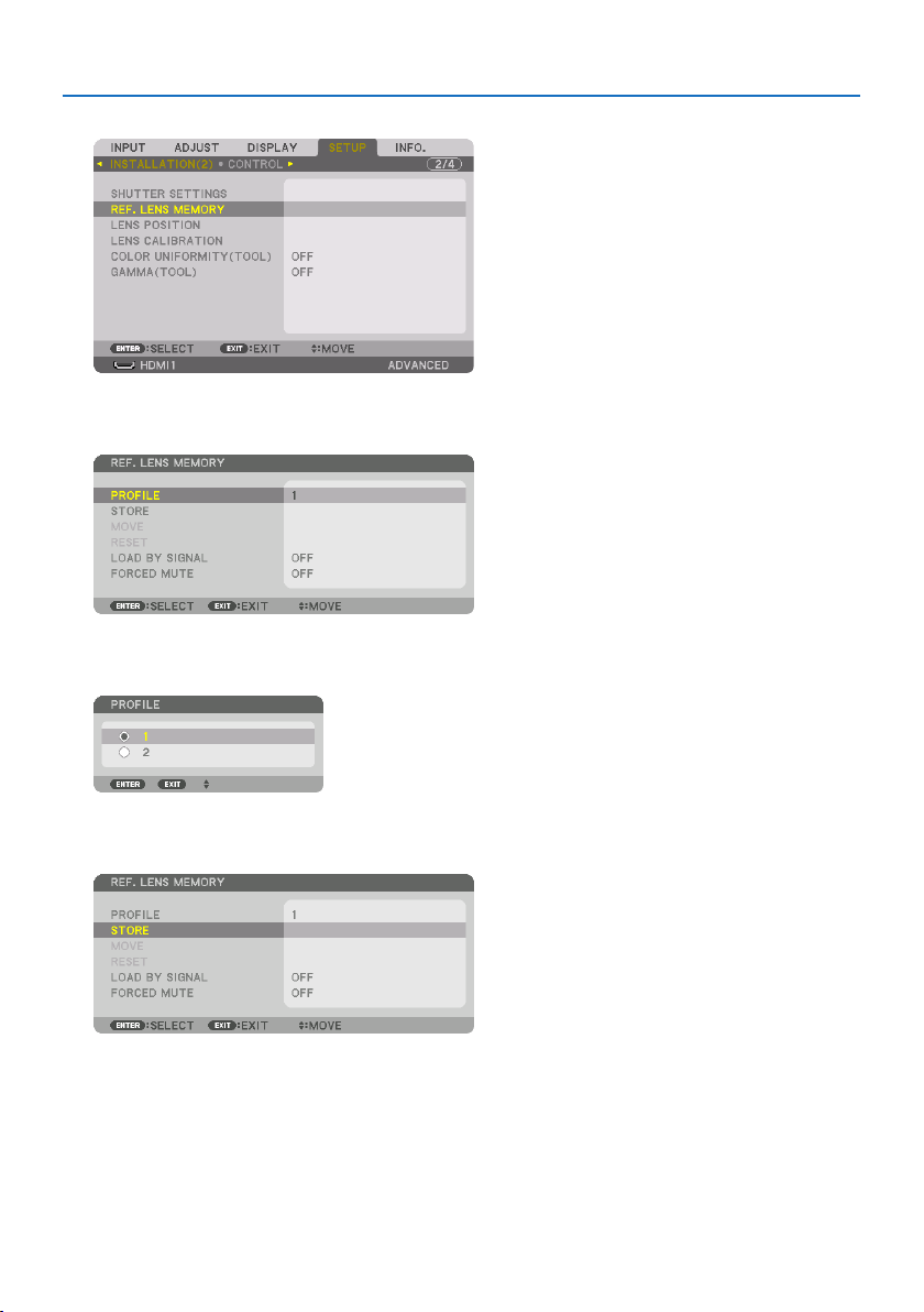
3. Convenient Features
61
4. Press the ▼buttontoselect[REF. LENS MEMORY] and press the ENTER button.
The [REF. LENS MEMORY] screen will be displayed.
5. Makesure[PROFILE] is highlighted, then press the ENTER button.
The [PROFILE] selection screen appears.
6. Press the ▼/▲buttonstoselectthe[PROFILE] number, then press the ENTER button.
Return to the [REF. LENS MEMORY] settings screen.
7. Select[STORE] and press the ENTER button.
The confirmation screen will be displayed.

3. Convenient Features
62
8. Press the ◀buttontoselectand[YES] and press the ENTER button.
Select a [PROFILE] number and save the adjusted [LENS SHIFT], [ZOOM], and [FOCUS] values to it.
9. Press the MENU button.
The menu will be closed.
TIP:
•Tostoreadjustedvaluesforeachinputsource,usethe[LENSMEMORY]function.(→ page 108)
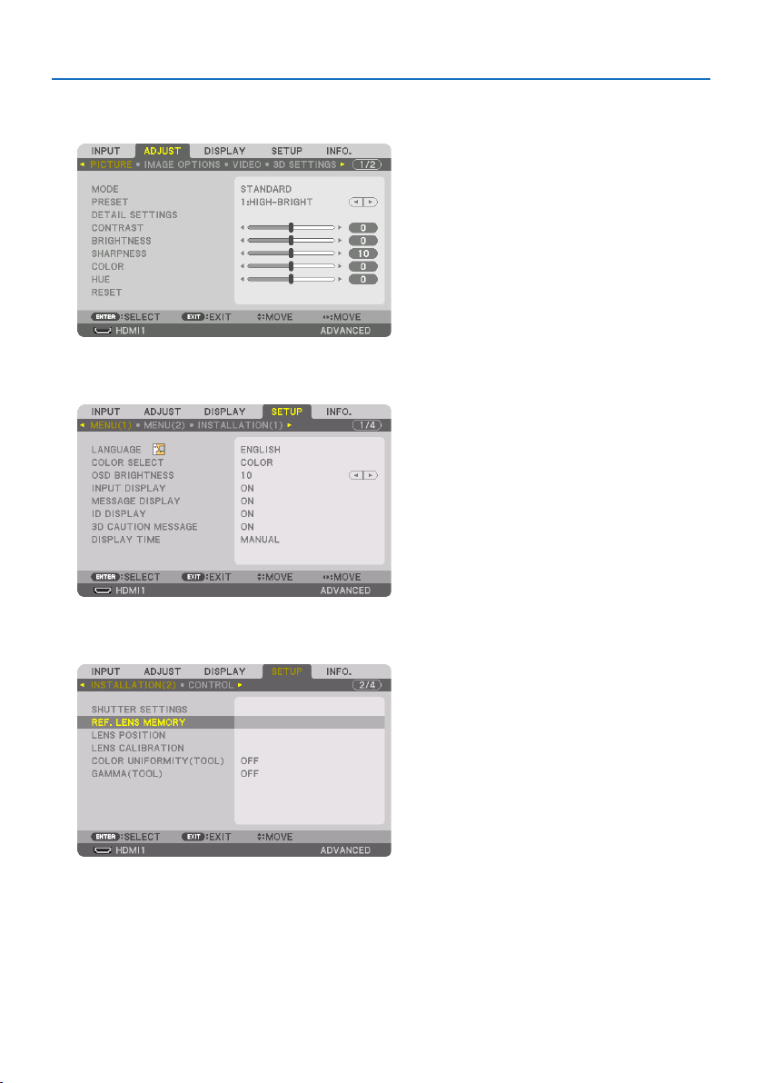
3. Convenient Features
63
To call up your adjusted values from [REF. LENS MEMORY]:
1. Press the MENU button.
The menu will be displayed.
2. Press the ▶buttontoselect[SETUP] and press the ENTER button.
3. Press the ▶buttontoselect[INSTALLATION(2)].
4. Press the ▼buttontoselect[REF. LENS MEMORY] and press the ENTER button.
The [REF. LENS MEMORY] screen will be displayed.
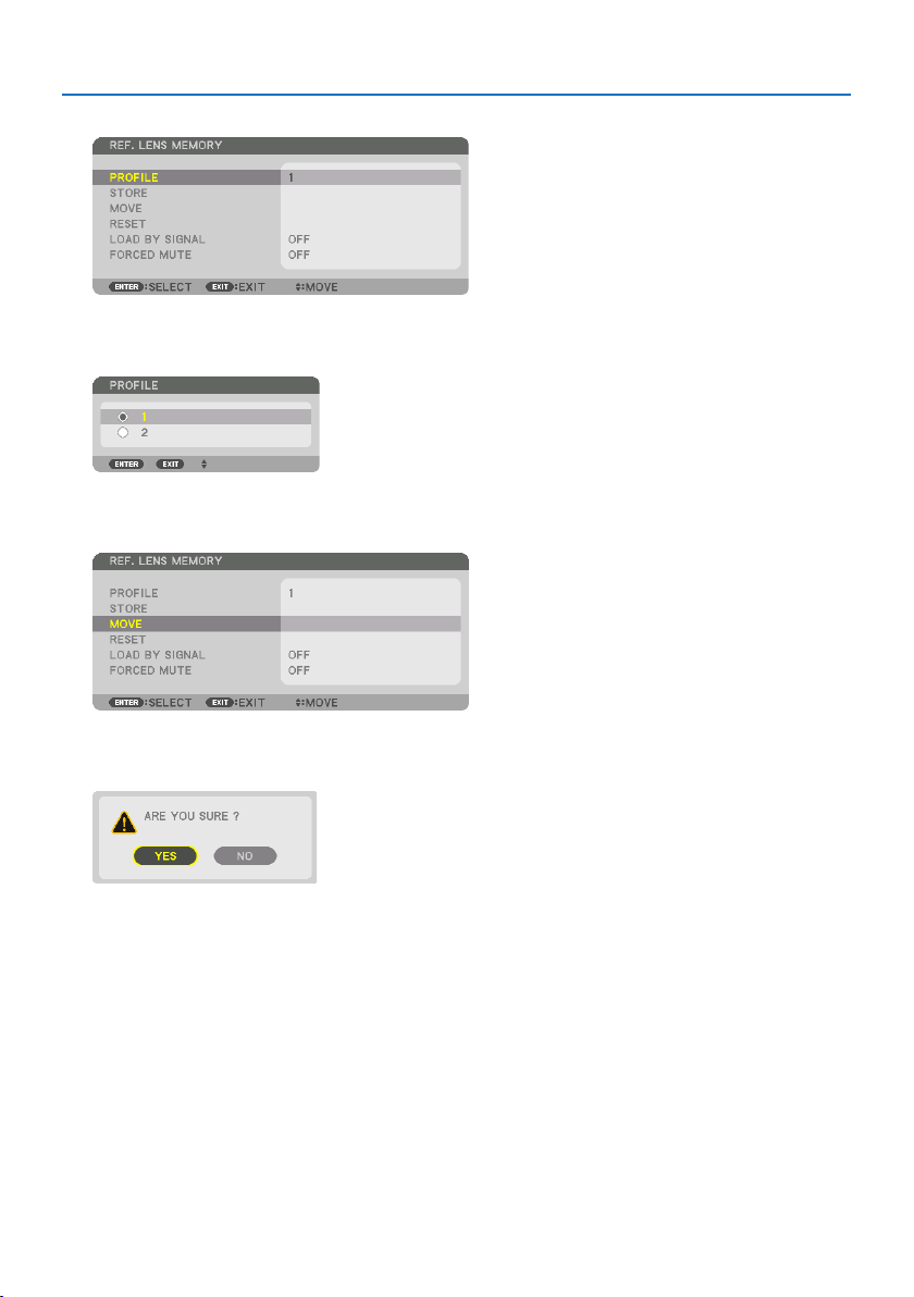
3. Convenient Features
64
5. Makesure[PROFILE] is highlighted, then press the ENTER button.
The [PROFILE] selection screen appears.
6. Press the ▼/▲buttonstoselectthe[PROFILE] number, then press the ENTER button.
Return to the [REF. LENS MEMORY] settings screen.
7. Select[MOVE] and press the ENTER button.
The lens will shift based on the adjusted values stored in the selected [PROFILE].
8. Press the ◀buttontoselectand[YES] and press the ENTER button.
The adjusted values will be applied to the current signal. .
9. Press the MENU button.
The menu will be closed.
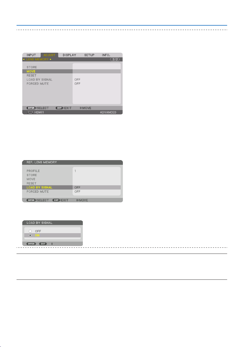
3. Convenient Features
65
TIP:
To call up the stored values from [LENS MEMORY]:
1.Fromthemenu,select[ADJUST] →[LENSMEMORY] →[MOVE]andpresstheENTERbutton.
Theconrmationscreenwillbedisplayed.
2.Pressthe◀buttontoselectand[YES]andpresstheENTERbutton.
Duringprojection,iftheadjustedvaluesforaninputsignalhavebeensaved,thelenswillshift.Ifnot,thelenswillshiftaccording
totheadjustedvaluesstoredintheselected[REF.LENSMEMORY] →[PROFILE]number.
To automatically apply the stored values at the time of source selection:
1.Fromthemenu,select[SETUP] →[REF.LENSMEMORY] →[LOADBYSIGNAL]andpresstheENTERbutton.
2.Pressthe▼buttontoselectand[ON]andpresstheENTERbutton.
Thiswillmovethelensautomaticallytothepositionatthetimeofsourceselectionaccordingtotheadjustedvalues.
NOTE:
•The[LENSMEMORY]functionmaynotproduceacompletelyalignedimage(duetotolerancesinthelenses)usingtheadjusted
valuesstoredintheprojector.Aftercallingupandapplyingthestoredvaluesfromthe[LENSMEMORY]function,nelyadjustthe
lensshift,motorizedzoomandmotorizedfocustoproducethebestpossibleimage.
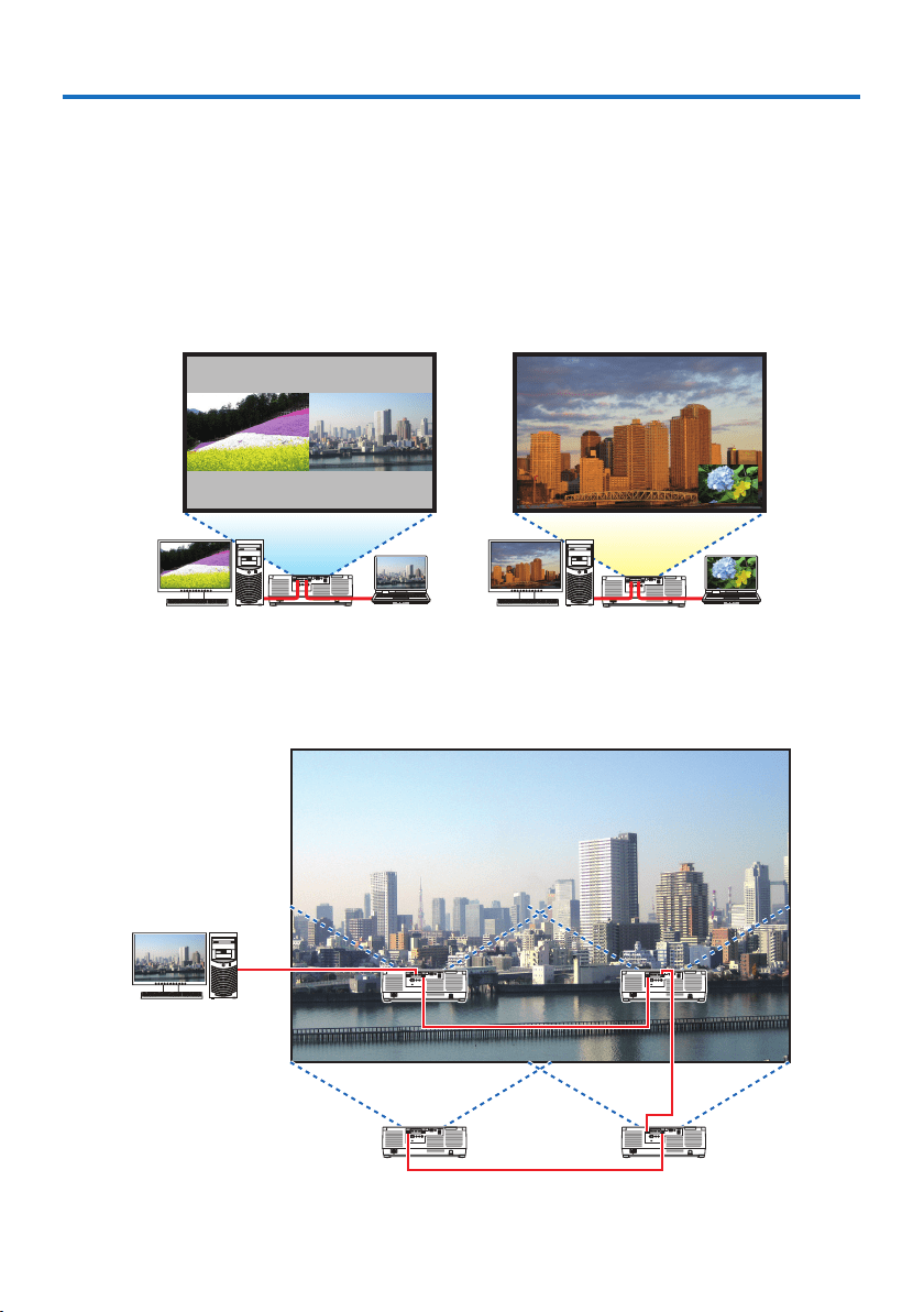
66
This projector can be used singly or arranged in multiple units for multi-screen projection.
4-1. Things that can be done using multi-screen projection
Case 1. Using a single projector to project two types of videos [PIP/PICTURE BY
PICTURE]
Connection example and projection image
In the case of [PICTURE BY PICTURE] In the case of [PIP]
Case 2. Lien up multiple projectors to project a high-resolution image in a
larger screen. [TILING]
Connection example and projection image
4. Multi-Screen Projection
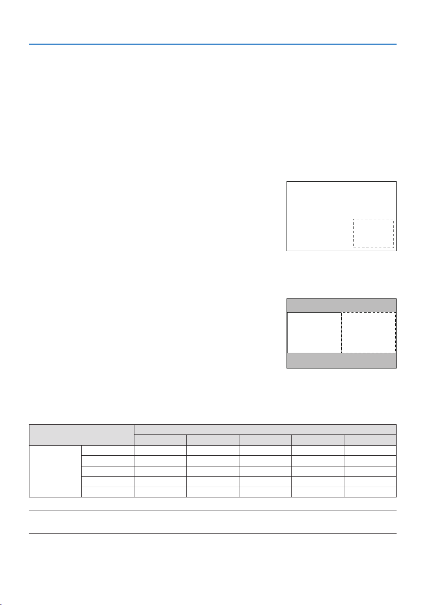
4. Multi-Screen Projection
67
4-2. Using a single projector to project two types of videos at the same
time [PIP/PICTURE BY PICTURE]
The projector has a feature that allows you to view two different signals simultaneously. You have
twomodes:[PIP] mode and [PICTURE BY PICTURE] mode.
The projection video in the first screen display is known as the main display while the projection
video that is called out subsequently is known as the sub-display.
Select the projection function under [DISPLAY] → [PIP/PICTURE BY PICTURE] → [MODE] in the on-
screen menu (the default factory setting when shipped is [PIP]). (→ page
111)
•Asinglescreenisprojectedwhenpoweristurnedon.
Picture in Picture function
A small sub-display is displayed inside the main display.
The sub-display can be set up and adjusted as follows. (→
page
111, 112)
•Selectwhethertodisplaythesub-displayatthetopright,
top left, bottom right or bottom left of the screen (the
size of the sub-display can be selected and the position
can be fine-tuned)
•Switchthemaindisplaywiththesub-display
MainDisplay
Sub-Display
Picture by picture function
Display the main display and sub-display side by side.
The main display and sub-display can be set up and ad-
justed as follows. (→ page
111, 112)
•Selectingthedisplayboundary(ratio)ofthemaindisplay
and sub-display
•Switchthemaindisplayandsub-display
MainDisplaySub-Display
Input terminals that can be used for the main screen and sub-screen.
The main screen and sub-screen can provide the following input terminals.
•Themaindisplayandsub-displaysupportcomputersignalsuptoWUXGA@60HzRB.
Sub-Display or additional display
HDMI1 HDMI2 DisplayPort COMPUTER HDBaseT
Main Display
HDMI1 No Yes Yes Yes Yes
HDMI2 Yes No Yes Yes Yes
DisplayPort Yes Yes No Yes Yes
COMPUTER Yes Yes Yes No Yes
HDBaseT Yes Yes Yes Yes No
NOTE:
•Somesignalsmaynotappeardependingontheresolution.
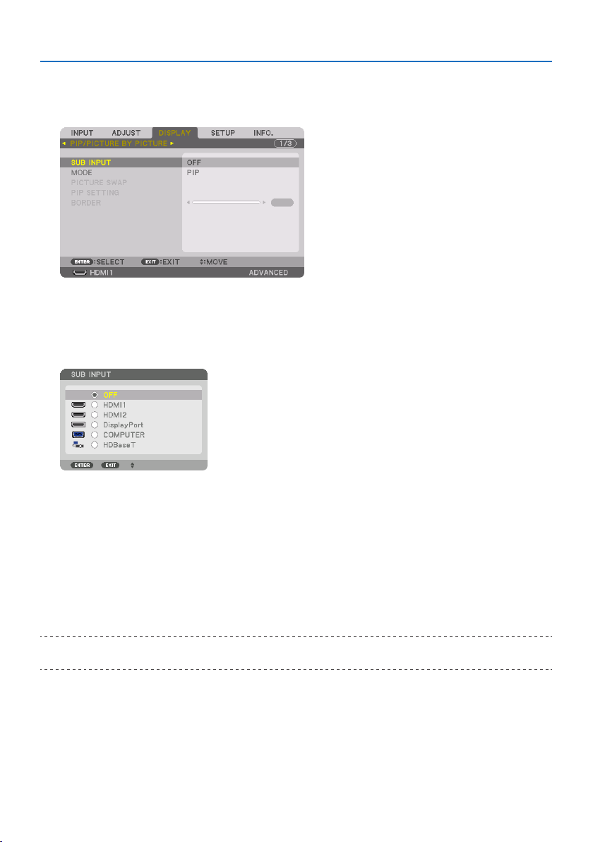
4. Multi-Screen Projection
68
Projecting two screens
1. Press the MENUbuttontodisplaytheon-screenmenuandselect[DISPLAY] →[PIP/PIC-
TURE BY PICTURE].
This displays the [PIP/PICTURE BY PICTURE] screen in the on-screen menu.
2. Select[SUB INPUT] using the ▼/▲ buttons, and press the ENTER button.
This displays the [SUB INPUT] screen.
3. Select the input signal using the ▼/▲ buttons, and press the ENTER button.
* This screen belongs to a HDBaseT model.
The [PIP] (PICTURE IN PICTURE) or [PICTURE BY PICTURE] screen set up under [MODE] is
projected. (→ page
111)
•Whenthesignalnameisdisplayedingrey,thismeansthatitcannotbeselected.
4. Press the MENU button.
The on-screen menu will disappear.
5. Whenreturningtosinglescreen,displaythe[PIP/PICTURE BY PICTURE] screen one more
timeandselect[OFF]inthe[SUB INPUT] screen of the Step 3.
TIP:
•Duringdual-screenprojection,iftheselectedinputisnotsupportedbythesub-screen,thesub-screenwillappearasablackscreen.
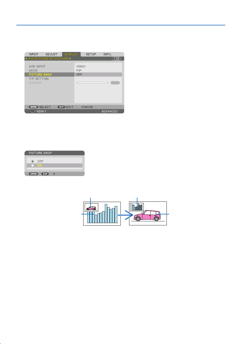
4. Multi-Screen Projection
69
Switching the main display with the sub-display and vice versa
1. Press the MENUbuttontodisplaytheon-screenmenuandselect[DISPLAY] →[PIP/PIC-
TURE BY PICTURE].
This displays the [PIP/PICTURE BY PICTURE] screen in the on-screen menu.
2. Select[PICTURE SWAP] using the ▼/▲ buttons and then press the ENTER button.
Display the screen for switching the display positions.
3. Select[ON] using the ▼ button and then press the ENTER button.
The video of the main display will switch with that of the sub-display.
When turned [OFF] When turned [ON]
Sub-display video
Main display video Sub-display video
Main display video
The signal output from the HDBaseT OUT/Ethernet terminal does not change even if the display
positions are switched.
4. Press the MENU button.
The on-screen menu will disappear.

4. Multi-Screen Projection
70
Restrictions
•Thefollowingoperationsareenabledonlyforthemaindisplay.
- Audio-visual adjustments
- Video magnification / compression using the partial VOL./D-ZOOM (+)(−) buttons.
However, magnification / compression is up to the positions set in [PICTURE BY PICTURE] →
[BORDER] only.
- TEST PATTERN
•[PIP/PICTURE BY PICTURE] cannot be used when a 3D video is being displayed.
•Whenusingthe[PIP/PICTURE BY PICTURE] function, [DYNAMIC CONTRAST] can not be used.
•[PIP/PICTURE BY PICTURE]cannotbeusedwhenthesignalinputhasaresolutionof1920×1200
or more.
•TheHDBaseT OUT/Ethernet port has a repeater function. The output resolution is limited by the
maximum resolution of the connected monitor and projector.
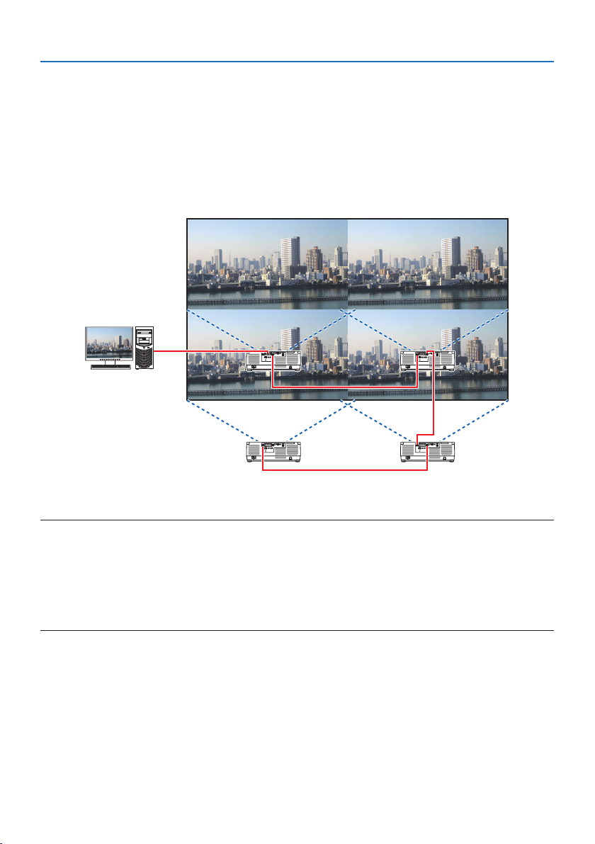
4. Multi-Screen Projection
71
4-3. Line up multiple projectors to display a high resolution image in a
larger screen [TILING]
Thissectionprovidesproceduresforprojectinganimagewitharesolutionof3840×2160(4KUHD)
by using four projectors.
Preparation:
•Arrangefourprojectorsina2×2layout.
Connect your video output equipment to the four projectors (→ page
167).
•Turnonthepowerofalldevicestoprojectthesamefourimages
When performing settings or adjustments using one remote control, enable the [CONTROL ID] for
assigning ID to each projector so as not to activate the other projectors. (→ page 138)
NOTE:
•Whensettinguptheprojector,assignauniquecontrolIDtoeachprojector.
•Setthe“Colorsetting”and“DeepColorsetting”onyourBlu-rayplayerorcomputerto“Auto”.Refertotheowner’smanualaccompanied
withyourBlu-rayplayerorcomputerformoreinformation.
•ConnectanHDMIoutputofyourBlu-rayplayerorcomputertotherstprojectorandthenconnecttoHDBaseTIN/Ethernet port
ofthesecondandsubsequentprojectors.
•SelectinganotherinputsourceonthesecondandsubsequentprojectorswilldisabletheHDBaseTrepeaterfunction.
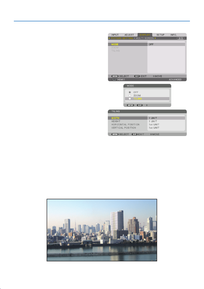
4. Multi-Screen Projection
72
Setting [TILING]
1. Press the MENU button to display the
on-screenmenuandselect[DISPLAY] →
[PICTURE SETTING] →[MODE].
This displays the [MODE] screen.
2.Select[TILING] using the ▼/▲ buttons, and
press the ENTER button.
The display returns to the [PICTURE SETTING]
screen.
3.Select[TILING] using the ▼/▲ buttons, and
press the ENTER button.
This displays the [TILING] screen.
4. Set[WIDTH],[HEIGHT],[HORIZONTAL POSITION],and[VERTICAL POSITION]
(1) In the screen for setting the number of horizontal units, select [2 UNITS]. (number of units
in the horizontal direction)
(2) In the screen for setting the number of vertical units, select [2 UNITS]. (number of units in
the vertical direction)
(3) In the screen for setting the horizontal order, select [1st UNIT] or [2nd UNIT]. (look at the
screens, the one on the left is the [1st UNIT] while the one on the right is the [2nd UNIT])
(4) In the screen for setting the vertical order, select the [1st UNIT] or the [2nd UNIT]. (look at the
screens, the one at the top is the [1st UNIT] while the one at the bottom is the [2nd UNIT])
After completing setting for the steps 1 to 4, a single image will be displayed to fill the screen.

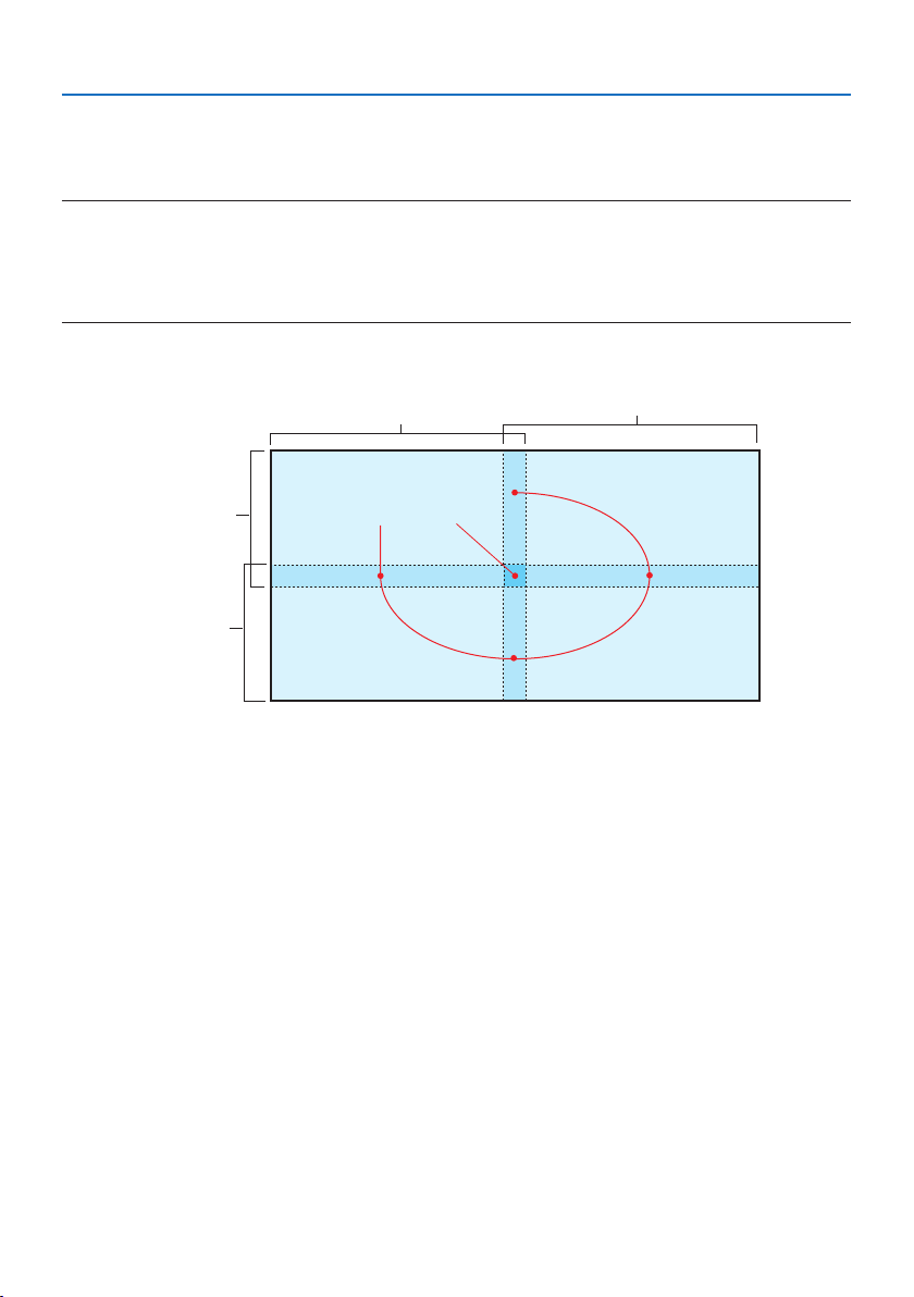
4. Multi-Screen Projection
74
4-4. Adjust boundaries of a projected image [EDGE BLENDING]
This projector is equipped with an “[EDGE BLENDING] Function” that makes the edges (boundaries)
of the projection screen indistinguishable.
NOTE:
•BeforeperformingtheEdgeBlendingfunction,placetheprojectorinthecorrectpositionsothattheimagebecomessquareinthe
appropriatesize,andthenmakeopticaladjustments(lensshift,focus,andzoom).
•Adjustthebrightnessofeachprojectorusing[REF.LIGHTADJUST]under[REF.LIGHTMODE].Inaddition,use[REF.WHITEBALANCE]
toadjustthe[CONTRAST],[BRIGHTNESS]and[UNIFORMITY].
Thefollowingprocedureshowsanexampleoffourprojectorsina2×2layout.
Edge Blending area
Projected area
Projected area
Projected area
Projected area
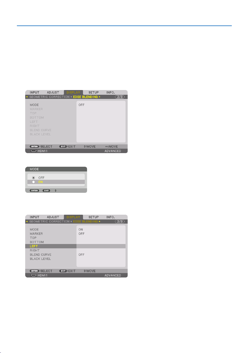
4. Multi-Screen Projection
75
Setting the overlap of projection screens
①Enable[EDGE BLENDING].
1. Press the MENU button.
The menu will be displayed.
2. Select[DISPLAY] →[EDGE BLENDING].
The [EDGE BLENDING] screen will be displayed. Align the cursor with [MODE] and then press
the ENTER button. The mode screen will be displayed.
3. Select[MODE] →[ON] and press the ENTER button.
ThisenablestheEdgeBlendingfunction.Thefollowingmenuitemsareavailable:
[MARKER], [TOP], [BOTTOM], [LEFT], [RIGHT], [BLEND CURVE], and [BLACK LEVEL]
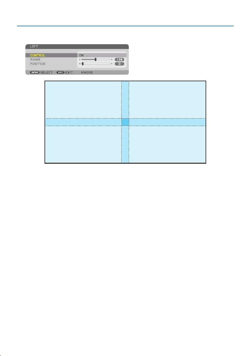
4. Multi-Screen Projection
76
4. Selectanappropriateitemfrom[TOP],[BOTTOM],[LEFT],and[RIGHT] for an area of
overlappededges,andturnon[CONTROL].
[TOP]:[OFF]
[BOTTOM]:[ON]
[LEFT]:[OFF] [RIGHT]:[ON]
[TOP]:[ON]
[BOTTOM]:[OFF]
[LEFT]:[OFF] [RIGHT]:[ON]
[TOP]:[OFF]
[BOTTOM]:[ON]
[LEFT]:[ON] [RIGHT]:[OFF]
[TOP]:[ON]
[BOTTOM]:[OFF]
[LEFT]:[ON] [RIGHT]:[OFF]
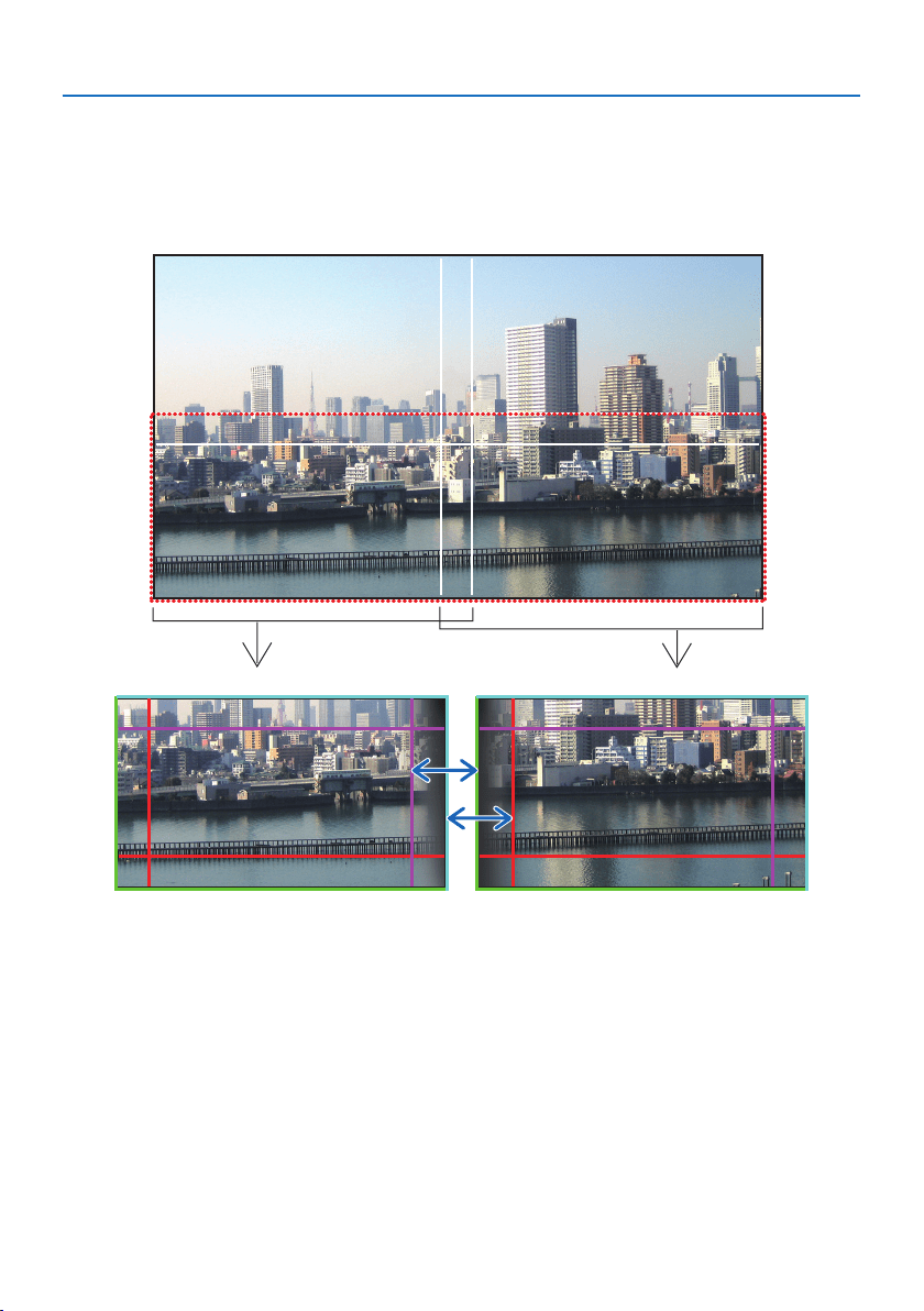
4. Multi-Screen Projection
77
②Adjust[POSITION]and[RANGE] to determine an area of overlapped edges of
images projected from each projector.
When [MARKER] is set to [ON], markers of four colors are displayed on the screen.
The cyan and green markers represent the edges of the region where images overlap, the magenta
and red markers represent the range of overlapping (region/width).
Turn on [RIGHT] Turn on [LEFT]
* The 2 screens are separated in the diagram for explanatory purposes.
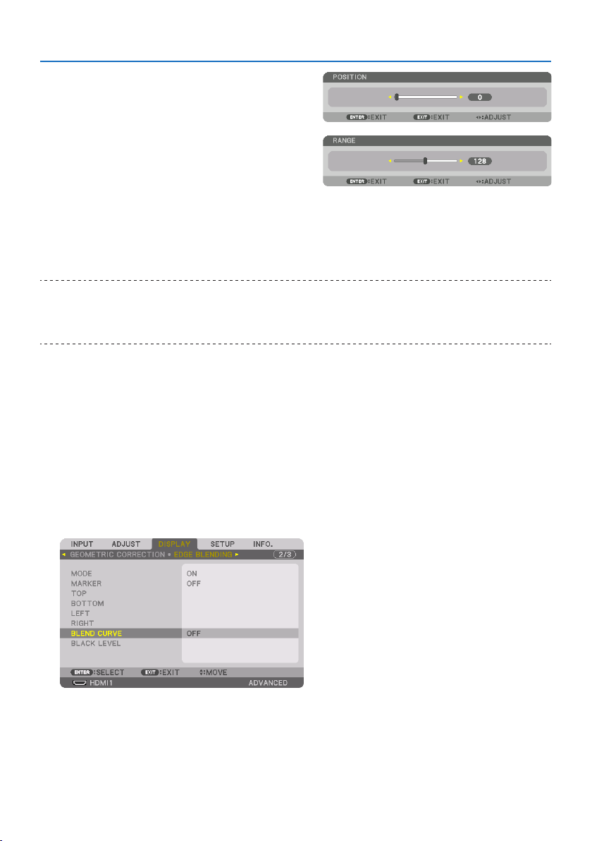
4. Multi-Screen Projection
78
Fit the edge of the overlapping area to the edge
of the image with [POSITION], then adjust the
overlapping area (width) with [RANGE]. In the
case of the figure on the previous page, first set
the cyan marker to the edge of the image on the
left screen and the green marker to the edge of
the image on the right screen. Next, adjust the
magenta marker on the left screen onto the green
marker on the right screen, and the red marker
on the right screen onto the cyan marker on the
left screen. Adjustment is completed when the
markers are stacked and become white. Turn off
[MARKER] to turn off the marker.
TIP:
•Whendisplayingasignalwithadierentresolution,performtheEdgeBlendingfunctionfromthestart.
•Settingof[MARKER]willnotbesavedandreturnto[OFF]whentheprojectoristurnedo.
•Todisplayorhidethemarkerwhiletheprojectorisrunning,turnonoro[MARKER]fromthemenu.
[BLEND CURVE]
Adjust the brightness of the overlapped section on the screens. According to the necessity, adjust
the brightness of the overlapped section on the screens by the [BLEND CURVE] and [BLACK LEVEL].
• Setthe[MODE] to [ON] for selecting [BLEND CURVE] and [BLACK LEVEL].
Selectinganoptionforthe[BLEND CURVE]
By controlling the graduation of the overlapped section on the screens, it makes the border on the
projected screens inconspicuous. Select the optimal option among nine.
1. OntheOn-ScreenMenu,movethecursorontothe[DISPLAY] →[EDGE BLENDING] →
[BLEND CURVE] and then press the ENTER.Theoptionsettingscreenforthe[BLEND CURVE]
is displayed on.
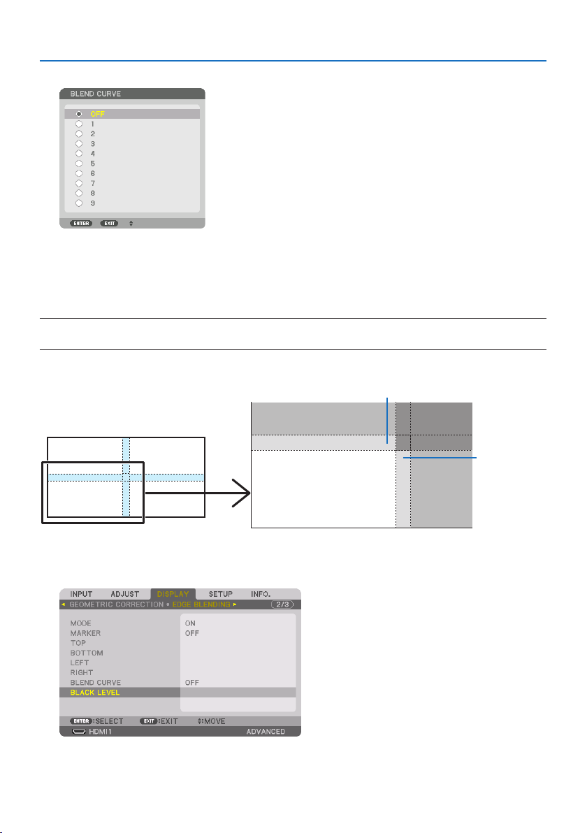
4. Multi-Screen Projection
79
2. Select one option among nine by ▲ or ▼.
Black Level Adjustment
This adjusts the black level of the overlapping area and the non-overlapping area of the multi-screen
(EDGE BLENDING).
Adjust the brightness level if you feel the difference is too large.
NOTE:
•Adjustableareavariesdependingonwhatcombinationof[TOP],[BOTTOM],[LEFT]and[RIGHT]areturnedon.
The black level of the lower left projector is adjusted as shown in the figure.
CENTER
TOP
RIGHT
BORDER (TOP)
BORDER
(RIGHT)
1. Select[DISPLAY] →[EDGE BLENDING] →[BLACK LEVEL] and press the ENTER button.
The screen will switch to the black level adjustment screen.
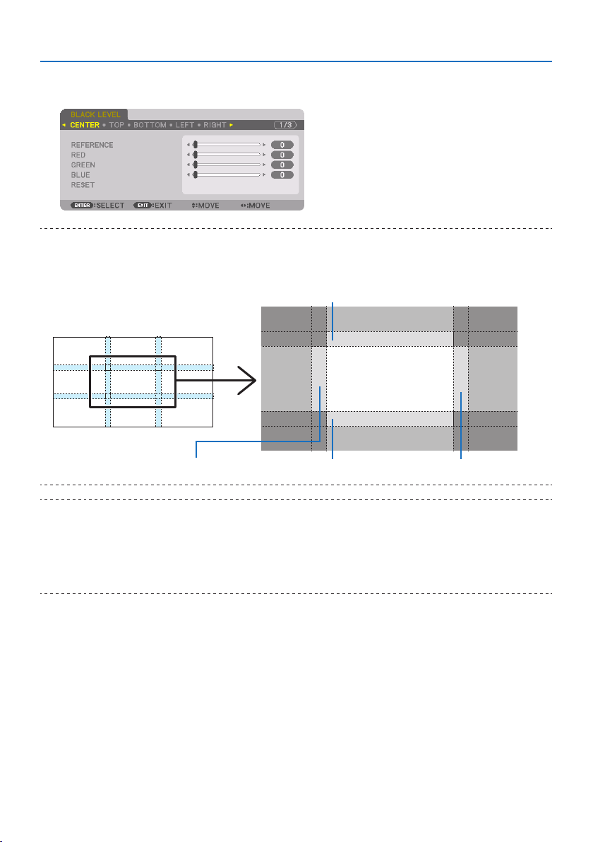
4. Multi-Screen Projection
80
2. Use the ◀, ▶, ▼ or ▲ button to select an item and use the ◀ or ▶ to adjust the black level.
Do this for the other projector if necessary.
TIP:
•9-segmentedportionsforBlackLeveladjustment
Theblacklevelofthecenterprojectorisadjustedasshowninthegure.
CENTER
BORDER (BOTTOM)BORDER (LEFT)
BORDER (TOP)
TOP
BOTTOM
RIGHTLEFT
BORDER (RIGHT)
TIP:
•Thenumberofblackleveldivisionscreenschangesdependingonthenumberofedgeblendingpositionsselected(top,bottom,
right,left).Inaddition,whenthetop/bottomandleft/rightendsareselected,thecornerdivisionscreenappears.
•Theedgeblendingwidthisthewidthsetintherangeandthecornerisformedbytheintersectingareaofthetop/bottomends
orleft/rightends.
•The[BLACKLEVEL]canbeadjustedtomakeitbrighteronly.

4. Multi-Screen Projection
81
Adjust using a computer or smartphone
[EDGE BLENDING] can be easily done using a computer or smartphone connected to the projectors
via a network.
Connect to the HTTP server (→ page
56) and display the [EDGE BLENDING] tab.
Screen for computer Screen for smartphone
The [EDGE BLENDING] setting/adjustment items are displayed on one screen and can be operated
using the mouse of the computer or the touch screen of the smartphone. For details of each setting/
adjustment, refer to the On-Screen Menu explanation.
•[POSITION] and [RANGE] can be adjusted by moving the markers (cyan, green, magenta, red line)
by clicking and dragging with the mouse (or swiping the smartphone).
•Thefollowingadjustmentvaluescanbenelyadjustedwiththe←/→buttononthekeyboard:
•POSITION
•RANGE
•[REFERENCE] for [BLACK LEVEL], [RED], [GREEN], BLUE]
•Tocheckwhichscreenoftheprojectoryouareadjusting,pressthe[IDENTIFICATION]button.The
identification message (IP address) will be displayed on the screen for 3 seconds.
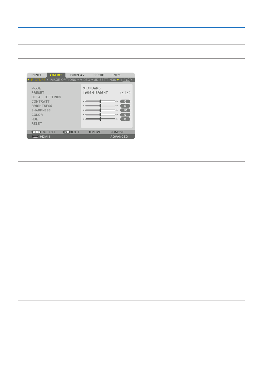
82
5-1. Using the Menus
NOTE:
•Theon-screenmenumaynotbedisplayedcorrectlywhileinterlacedmotionvideoimageisprojected.
1. Press the MENU button on the remote control or the projector cabinet to display the menu.
NOTE:
•ThecommandssuchasENTER,EXIT,▲▼,◀▶inthebottomshowavailablebuttonsforyouroperation.
2. Press the ◀▶ buttons on the remote control or the projector cabinet to display the sub-
menu.
3. Press the ENTER button on the remote control or the projector cabinet to highlight the
top item or the first tab.
4. Use the ▲▼ buttons on the remote control or the projector cabinet to select the item you
want to adjust or set.
You can use the ◀▶ buttons on the remote control or the projector cabinet to select the tab
you want.
5. Press the ENTER button on the remote control or the projector cabinet to display the
submenu window.
6. Adjustthelevelorturntheselecteditemonorobyusingthe▲▼◀▶ buttons on the
remote control or the projector cabinet.
Changes are stored until adjusted again.
7. Repeat steps 2-6 to adjust an additional item, or press the EXIT button on the remote
control or the projector cabinet to quit the menu display.
NOTE:
•Whenamenuormessageisdisplayed,severallinesofinformationmaybelost,dependingonthesignalorsettings.
8. Press the MENU button to close the menu.
To return to the previous menu, press the EXIT button.
5. Using On-Screen Menu
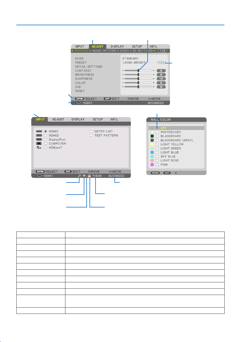
5. Using On-Screen Menu
83
5-2. Menu Elements
Slide bar
Solid triangle
Tab
Radio button
High Altitude symbol
REF. LIGHT MODE symbol
Menu windows or dialog boxes typically have the following elements:
Highlight Indicatestheselectedmenuoritem.
SolidtriangleIndicatesfurtherchoicesareavailable.Ahighlightedtriangleindicatestheitemisactive.
TabIndicatesagroupoffeaturesinadialogbox.Selectingonanytabbringsitspagetothefront.
RadiobuttonUsethisroundbuttontoselectanoptioninadialogbox.
SourceIndicatesthecurrentlyselectedsource.
MenumodeIndicatesthecurrentmenumode:[BASIC]or[ADVANCED].
OTimerremainingtimeIndicatestheremainingcountdowntimewhenthe[OFFTIMER]ispreset.
SlidebarIndicatessettingsorthedirectionofadjustment.
REF.LIGHTMODEsymbolIndicates[REF.LIGHTMODE]isset.
KeyLocksymbolIndicatesthe[CONTROLPANELLOCK]isenabled.
ThermometersymbolIndicatesthe[LIGHTMODE]isforciblysetto[ON]modebecausetheinternaltemperatureistoo
high.
HighAltitudesymbolIndicatesthe[FANMODE]issetto[HIGHALTITUDE]mode.
Source
Available buttons
Thermometer symbol Key Lock symbol
Off Timer remaining time
Menu mode
Highlight
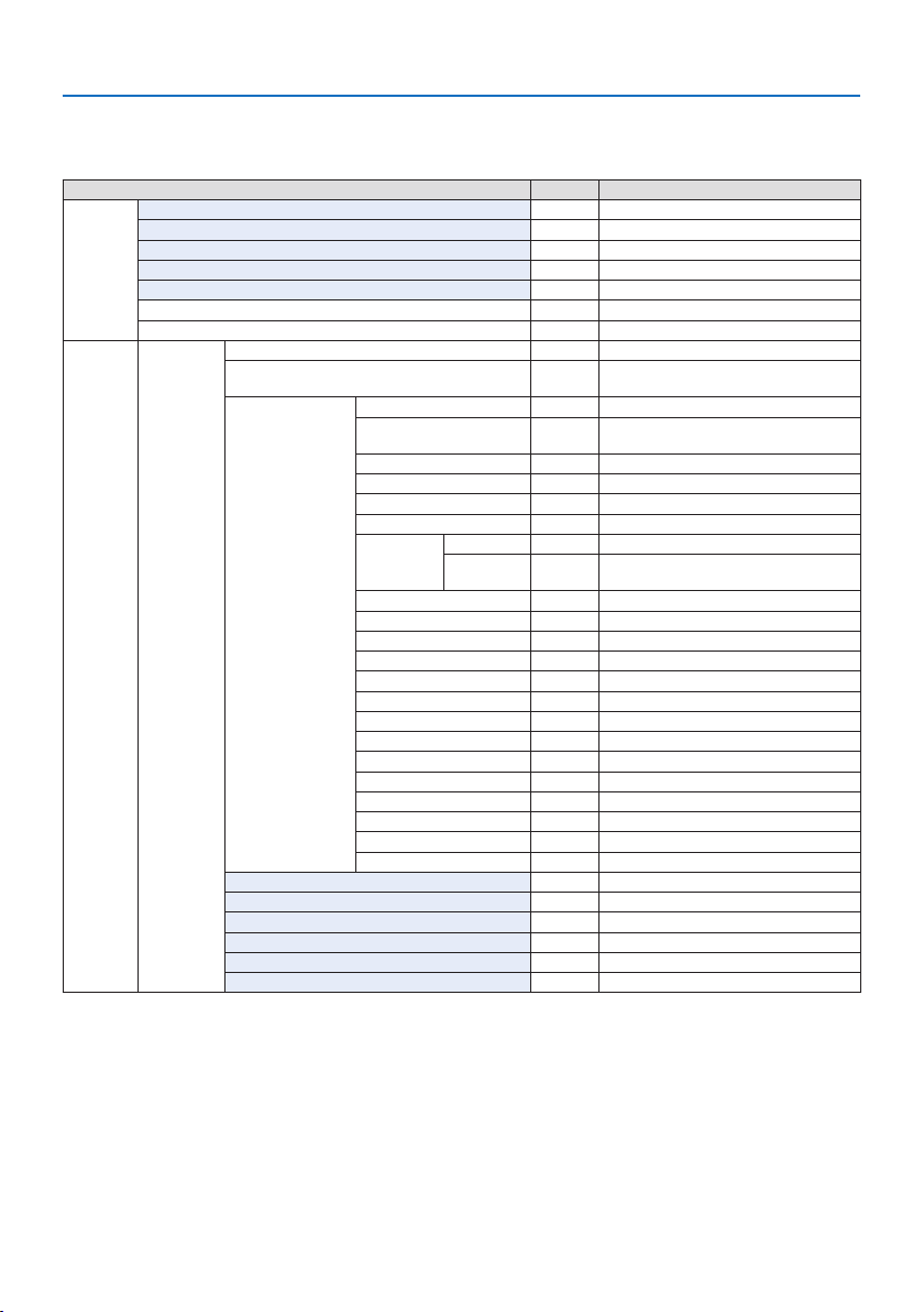
5. Using On-Screen Menu
84
5-3. List of Menu Items
Some menu items are not available depending on the input source.
MenuItemDefault Options
INPUTHDMI1*
HDMI2*
DisplayPort*
COMPUTER*
HDBaseT
ENTRYLIST
TESTPATTERN
ADJUSTPICTUREMODE STANDARDSTANDARD,PROFESSIONAL
PRESET*AUTO,1:HIGH-BRIGHT,2:PRESENTATION,3:VIDEO,
4:MOVIE,5:GRAPHIC,6:sRGB,7:DICOMSIM.
DETAILSETTINGSGENERAL
REFERENCE*HIGH-BRIGHT,PRESENTATION,VIDEO,MOVIE,GRAPHIC,
sRGB,DICOMSIM.
GAMMASETTING*
1
SCREENSIZE*
2
*LARGE,MEDIUM,SMALL
COLORTEMPERATURE*
3
*
DYNAMICCONTRAST*OFF,MOTIONIMAGE,STILLIMAGE
LIGHTMODELIGHTADJUST*
CONSTANT
BRIGHTNESS
OFFOFF,ON
WHITEBALANCE
CONTRASTR0
CONTRASTG0
CONTRASTB0
BRIGHTNESSR0
BRIGHTNESSG0
BRIGHTNESSB0
COLORCORRECTION
RED 0 HUE,SATURATION
GREEN0 HUE,SATURATION
BLUE 0 HUE,SATURATION
YELLOW0 HUE,SATURATION
MAGENTA0 HUE,SATURATION
CYAN0 HUE,SATURATION
CONTRAST50
BRIGHTNESS50
SHARPNESS10
COLOR 50
HUE 0
RESET
* The asterisk (*) indicates that the default setting varies depending on the signal.
*1 The [GAMMA SETTING] item is available when an item other than [DICOM SIM.] is selected for [REFERENCE].
*2 The [SCREEN SIZE] item is available when [DICOM SIM.] is selected for [REFERENCE].
*3 When [HIGH-BRIGHT] is selected in [REFERENCE], the [COLOR TEMPERATURE] is not available.
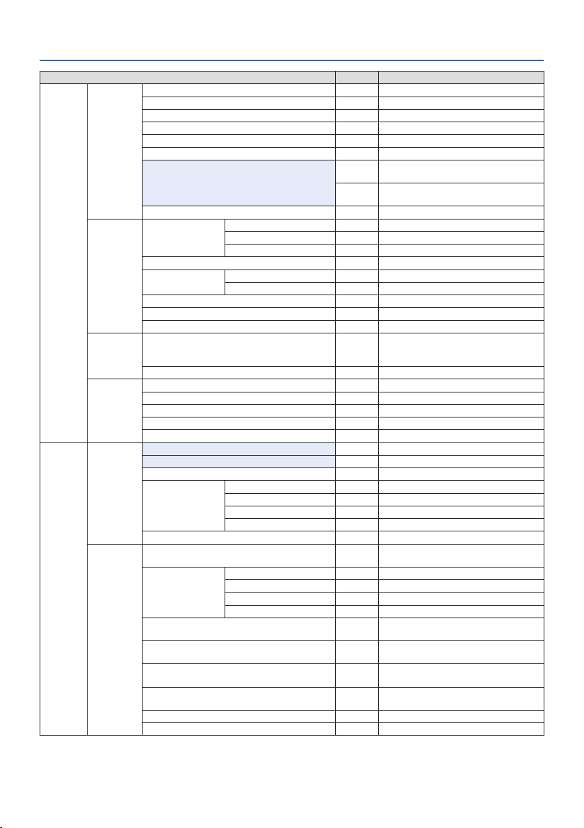
5. Using On-Screen Menu
85
MenuItemDefault Options
ADJUSTIMAGEOPTIONSCLOCK*
PHASE*
HORIZONTAL*
VERTICAL*
BLANKING*TOP,BOTTOM,LEFT,RIGHT
OVERSCANAUTO,0[%],5[%],10[%]
ASPECTRATIOAUTO(HDTV/SDTV)AUTO,NORMAL,4:3,LETTERBOX,WIDE
SCREEN,ZOOM,FULL
AUTO(COMPUTER) AUTO,NORMAL,4:3,5:4,16:9,15:9,16:10,
FULL,NATIVE
INPUTRESOLUTION*
4
*–
VIDEONOISEREDUCTIONRANDOMNR*OFF,LOW,MEDIUM,HIGH
MOSQUITONROFFOFF,LOW,MEDIUM,HIGH
BLOCKNROFFOFF,LOW,MEDIUM,HIGH
DEINTERLACENORMALNORMAL,MOVIE,STILL
CONTRASTENHANCEMENTMODE AUTOOFF,AUTO,NORMAL
GAIN
SIGNALTYPEAUTOAUTO,RGB,REC601,REC709,REC2020
VIDEOLEVELAUTOAUTO,NORMAL,ENHANCED,SUPERWHITE
HDR MODE*
5
AUTOAUTO,OFF,ON
3DSETTINGSFORMATAUTOAUTO,OFF(2D),FRAMEPACKING,SIDEBYSIDE(HALF),SIDE
BYSIDE(FULL),TOPANDBOTTOM,FRAMEALTERNATIVE,
LINEALTERNATIVE
L/RINVERTOFFOFF,ON
LENSMEMORYSTORE
MOVE
RESET
LOADBYSIGNALOFFOFF,ON
FORCEDMUTEOFFOFF,ON
DISPLAYPIP/PICTUREBY
PICTURE
SUBINPUTOFFOFF,HDMI1,HDMI2,DisplayPort,COMPUTER,HDBaseT
MODE PIPPIP,PICTUREBYPICTURE
PICTURESWAPOFFOFF,ON
PIPSETTINGSTARTPOSITIONTOP-LEFTTOP-LEFT,TOP-RIGHT,BOTTOM-LEFT,BOTTOM-RIGHT
HORIZONTALPOSITION
VERTICALPOSITION
SIZEMEDIUMLARGE,MEDIUM,SMALL
BORDER
GEOMETRIC
CORRECTION
MODE OFFOFF,KEYSTONE,CORNERSTONE,HORIZONTALCORNER,
VERTICALCORNER,WARP,PCTOOL
KEYSTONEHORIZONTAL
VERTICAL
TILT
THROWRATIO
CORNERSTONETOP-LEFT,TOP,TOP-RIGHT,LEFT,RIGHT,BOTTOM-LEFT,
BOTTOM,BOTTOM-RIGHT
HORIZONTALCORNERTOP-LEFT,TOP,TOP-RIGHT,LEFT,RIGHT,BOTTOM-LEFT,
BOTTOM,BOTTOM-RIGHT
VERTICALCORNERTOP-LEFT,TOP,TOP-RIGHT,LEFT,RIGHT,BOTTOM-LEFT,
BOTTOM,BOTTOM-RIGHT
WARPTOP-LEFT,TOP,TOP-RIGHT,LEFT,RIGHT,BOTTOM-LEFT,
BOTTOM,BOTTOM-RIGHT
PCTOOLOFFOFF,1,2,3
RESET
*4 The [INPUT RESOLUTION] item can be selected for [COMPUTER] input.
*5 The [HDR MODE] item is available exclusively for 4K signal.
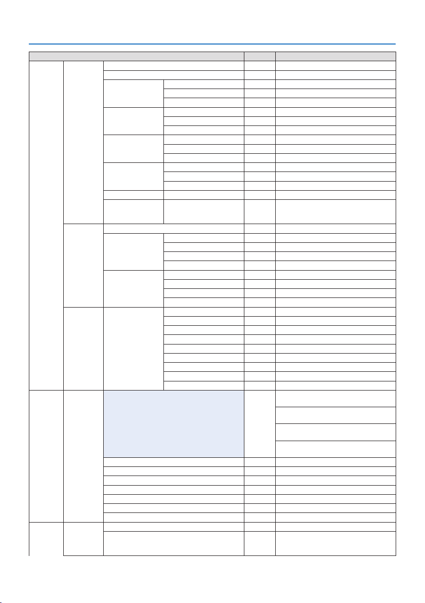
5. Using On-Screen Menu
86
MenuItemDefault Options
DISPLAYEDGEBLENDINGMODE OFFOFF,ON
MARKEROFFOFF,ON
TOPCONTROL ON OFF,ON
RANGE
POSITION
BOTTOM CONTROL ON OFF,ON
RANGE
POSITION
LEFTCONTROL ON OFF,ON
RANGE
POSITION
RIGHTCONTROL ON OFF,ON
RANGE
POSITION
BLEND CURVE 5 OFF,1,2,3,4,5,6,7,8,9
BLACKLEVELCENTER,TOP,BOTTOM,LEFT,RIGHT,
BORDER(TOP),BORDER(BOTTOM),
BORDER(LEFT),BORDER(RIGHT)
REFERENCE,RED,GREEN,BLUE,RESET
PICTURESETTINGMODE OFFOFF,ZOOM,TILING
ZOOM HORIZONTALZOOM
VERTICALZOOM
HORIZONTALPOSITION
VERTICALPOSITION
TILINGWIDTH1UNIT,2UNITS,3UNITS,4UNITS
HEIGHT1UNIT,2UNITS,3UNITS,4UNITS
HORIZONTALPOSITION1stUNIT,2ndUNIT,3rdUNIT,4thUNIT
VERTICALPOSITION1stUNIT,2ndUNIT,3rdUNIT,4thUNIT
MULTISCREENWHITEBALANCEMODE OFFOFF,ON
CONTRASTW
CONTRASTR
CONTRASTG
CONTRASTB
BRIGHTNESSW
BRIGHTNESSR
BRIGHTNESSG
BRIGHTNESSB
SETUPMENU(1) LANGUAGEENGLISHENGLISH,DEUTSCH,FRANÇAIS,ITALIANO,ESPAÑOL,
SVENSKA,日本語
DANSK,PORTUGUÊS,ČEŠTINA,MAGYAR,POLSKI,
NEDERLANDS,SUOMI
NORSK,TÜRKÇE,РУССКИЙ,,Ελληνικά,简体中
文,한국어
ROMÂNĂ,HRVATSKA,БЪЛГАРСКИ,INDONESIA,,
ไทย,,繁體中文,Tiếng Việt
COLORSELECTCOLOR COLOR,MONOCHROME
OSDBRIGHTNESS10 1,2,3,4,5,6,7,8,9,10
INPUTDISPLAYON OFF,ON
MESSAGEDISPLAYON OFF,ON
IDDISPLAYON OFF,ON
3DCAUTIONMESSAGEON OFF,ON
DISPLAYTIMEAUTO45SECMANUAL,AUTO5SEC,AUTO15SEC,AUTO45SEC
SETUPMENU(2) MENUANGLE0° 0°,90°,270°
MENUPOSITIONCENTER TOP-LEFT,TOP-CENTER,TOP-RIGHT,CENTER-LEFT,
CENTER,CENTER-RIGHT,BOTTOM-LEFT,BOTTOM-CENTER,
BOTTOM-RIGHT

5. Using On-Screen Menu
87
MenuItemDefault Options
INSTALLATION(1)ORIENTATIONAUTOAUTO,DESKTOPFRONT,CEILINGREAR,DESKTOPREAR,
CEILINGFRONT
SCREENSCREENTYPEFREEFREE,4:3SCREEN,16:9SCREEN,16:10SCREEN
POSITION
WALLCOLOROFFOFF,WHITEBOARD,BLACKBOARD,BLACKBOARD(GRAY),
LIGHTYELLOW,LIGHTGREEN,LIGHTBLUE,SKYBLUE,
LIGHTROSE,PINK
FANMODEAUTOAUTO,NORMAL,HIGH,HIGHALTITUDE
REF.LIGHTMODEREF.LIGHTMODENORMALBOOST,NORMAL,ECO1,ECO2
REF.LIGHTADJUST
CONSTANTBRIGHTNESSOFFOFF,ON
REF.WHITEBALANCE CONTRASTR
CONTRASTG
CONTRASTB
BRIGHTNESSR
BRIGHTNESSG
BRIGHTNESSB
UNIFORMITYR
UNIFORMITYB
STATICCONVERGENCE HORIZONTALR
HORIZONTALG
HORIZONTALB
VERTICALR
VERTICALG
VERTICALB
INSTALLATION(2)SHUTTERSETTINGSPOWERONSHUTTEROPENOPEN,CLOSE
PICTUREMUTESHUTTEROPENOPEN,CLOSE
FADEINTIME0 0–10SEC
FADEOUTTIME0 0–10SEC
REF.LENSMEMORYPROFILE1 1,2
STORE
MOVE
RESET
LOADBYSIGNALOFFOFF,ON
FORCEDMUTEOFFOFF,ON
LENSPOSITIONHOME
LENSCALIBRATION
COLORUNIFORMITY(TOOL)OFFOFF,1,2,3
GAMMA(TOOL)OFFOFF,1,2,3
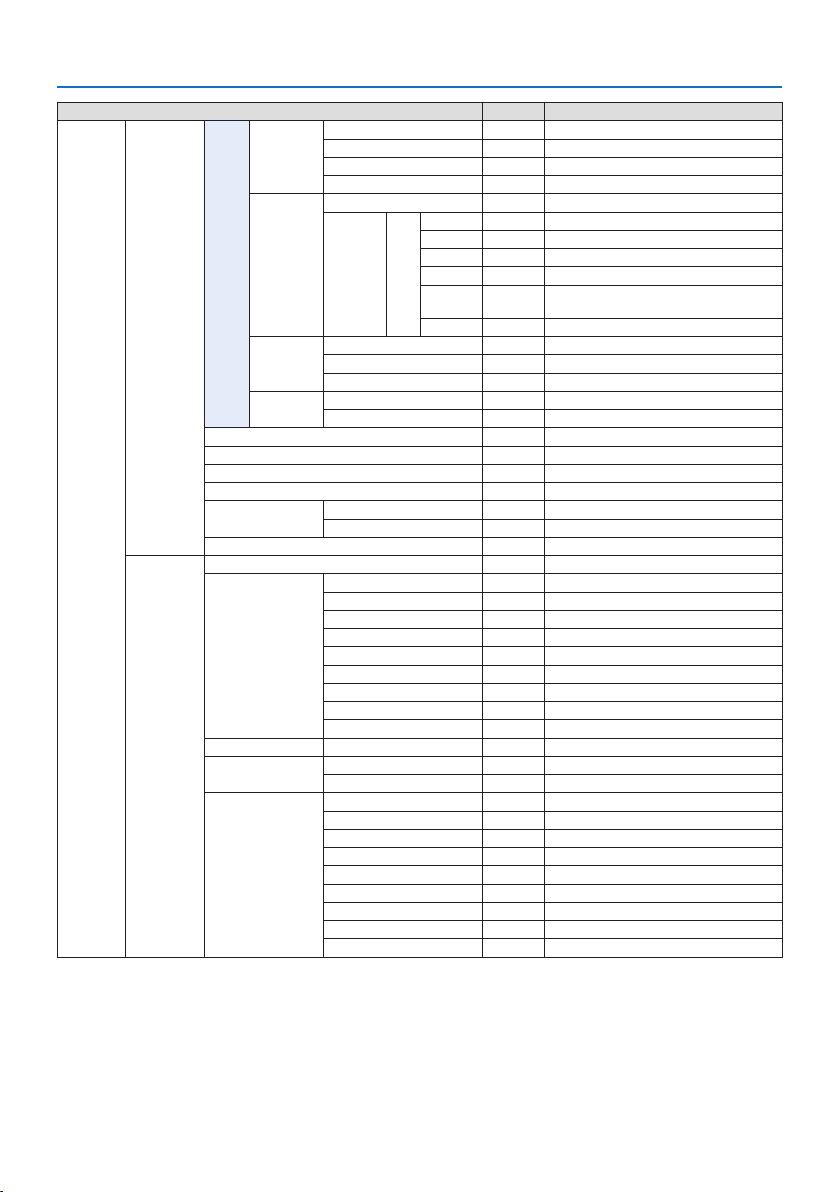
5. Using On-Screen Menu
88
MenuItemDefault Options
SETUPCONTROL TOOLSADMINISTRATOR
MODE
MENU MODE ADVANCEDADVANCED,BASIC
NOTSAVESETTINGVALUESOFFOFF,ON
NEWPASSWORD
CONFIRMPASSWORD
PROGRAM
TIMER
ENABLEOFFOFF,ON
SETTINGSEDITACTIVE
DAY
TIME
FUNCTION
ADVANCED
SETTINGS
REPEAT
DATEANDTIME
SETTINGS
TIMEZONESETTINGS
DATEANDTIMESETTINGS
SUMMERTIMESETTINGS
MOUSEBUTTON RIGHTHANDRIGHTHAND,LEFTHAND
SENSITIVITYMEDIUMFAST,MEDIUM,SLOW
CONTROLPANELLOCKOFFOFF,ON
SECURITYOFFOFF,ON
COMMUNICATIONSPEED38400bps4800bps,9600bps,19200bps,38400bps,115200bps
PCCONTROL(HDBaseT)OFFOFF,ON
CONTROLIDCONTROLIDNUMBER1 1–254
CONTROLIDOFFOFF,ON
REMOTESENSORFRONT/BACKFRONT/BACK,FRONT,BACK,HDBaseT
NETWORK
SETTINGS
NETWORKPASSWORD
WIREDLANINTERFACELAN,HDBaseT
PROFILESDISABLE,PROFILE1,PROFILE2
DHCPOFF,ON
IPADDRESS
SUBNETMASK
GATEWAY
AUTODNSOFF,ON
DNSCONFIGURATION
RECONNECT
PROJECTORNAMEPROJECTORNAMEPJ-********
DOMAINHOSTNAMEpj-********
DOMAINNAME
ALERTMAILALERTMAILOFF,ON
HOSTNAMEpj-********
DOMAINNAME
SENDER'SADDRESS
SMTPSERVERNAME
RECIPIENT'SADDRESS1
RECIPIENT'SADDRESS2
RECIPIENT'SADDRESS3
TESTMAIL
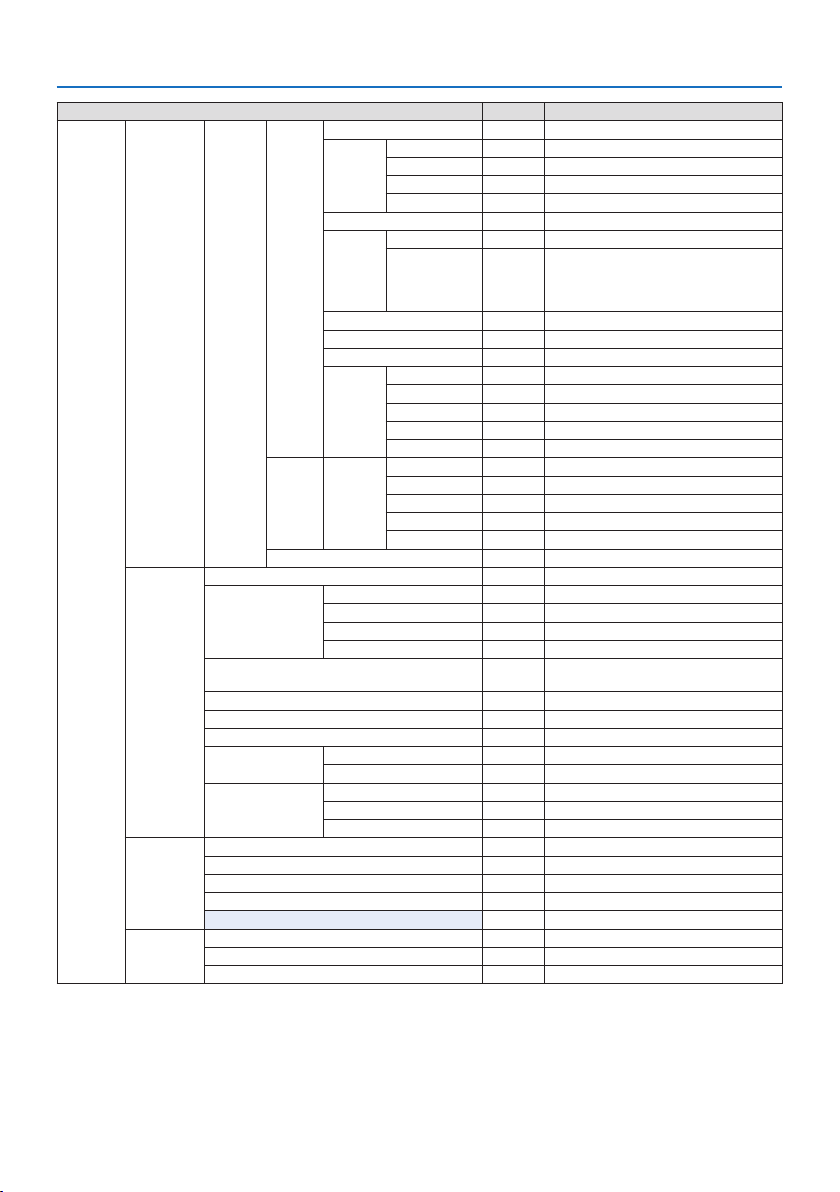
5. Using On-Screen Menu
89
MenuItemDefault Options
SETUPNETWORK
SETTINGS
NETWORK
SERVICE
SERVICESHTTPSERVERON OFF,ON,AUTH.
PJLinkNEWPASSWORD
CONFIRMPASSWORD
CLASSCLASS1,CLASS2
DESTINATION
AMXBEACONOFFOFF,ON
CRESTRONROOMVIEWOFFOFF,ON
CRESTRON
CONTROL (ENABLE,
CONTROLLERIP
ADDRESS,IPID)
ExtronXTPOFFOFF,ON
PCCONTROLON OFF,ON
AUTH.PCCONTROLON OFF,ON
Art-NetArt-NetOFFOFF,ON
[2.x.x.x]
[10.x.x.x]
SETTINGS
CHANNEL
ACCOUNTUSER1,
USER2,
USER3
REGISTER
CHANGEUSERNAME
CHANGEPASSWORD
ENABLEON OFF,ON
DELETE
PASSCODE
SOURCEOPTIONSAUTOADJUSTNORMALOFF,NORMAL,FINE
AUDIOSELECTHDMI1HDMI1HDMI1,COMPUTER
HDMI2HDMI2HDMI2,COMPUTER
DisplayPortDisplayPortDisplayPort,COMPUTER
HDBaseT HDBaseT HDBaseT,COMPUTER
DEFAULTINPUTSELECTLASTLAST,AUTO,HDMI1,HDMI2,DisplayPort,COMPUTER,
HDBaseT
SEAMLESSSWITCHINGOFFOFF,ON
BACKGROUNDBLUE BLUE,BLACK,LOGO
HDBaseTOUTSELECTOFFOFF,AUTO,HDMI1,HDMI2,DisplayPort,HDBaseT
EDIDVERSIONHDMI1MODE1 MODE1,MODE2
HDMI2MODE1 MODE1,MODE2
HDCPVERSIONHDMI1HDCP2.2HDCP2.2,HDCP1.4
HDMI2HDCP2.2HDCP2.2,HDCP1.4
HDBaseT HDCP1.4HDCP2.2,HDCP1.4
POWEROPTIONSPOWER-SAVINGON OFF,ON
DIRECTPOWERONOFFOFF,ON
AUTOPOWERONSELECTOFFOFF,HDMI1,HDMI2,DisplayPort,COMPUTER,HDBaseT
AUTOPOWEROFF0:15 OFF,0:05,0:10,0:15,0:20,0:30,1:00
OFFTIMEROFFOFF,0:30,1:00,2:00,4:00,8:00,12:00,16:00
RESETCURRENTSIGNAL
ALLDATA
ALLDATA(INCLUDINGENTRYLIST)

5. Using On-Screen Menu
90
MenuItemDefault Options
INFO.USAGETIMELIGHTHOURSUSED
PROJECTORHOURSUSED
TOTALCARBONSAVINGS
SOURCE(1)INPUTTERMINAL
RESOLUTION
HORIZONTALFREQUENCY
VERTICALFREQUENCY
SYNCTYPE
SYNCPOLARITY
SCANTYPE
SOURCENAME
ENTRYNO.
SOURCE(2)SIGNALTYPE
BITDEPTH
VIDEOLEVEL
SAMPLINGFREQUENCY
3DFORMAT
SOURCE(3)INPUTTERMINAL
RESOLUTION
HORIZONTALFREQUENCY
VERTICALFREQUENCY
SYNCTYPE
SYNCPOLARITY
SCANTYPE
SOURCENAME
ENTRYNO.
SOURCE(4)SIGNALTYPE
BITDEPTH
VIDEOLEVEL
SAMPLINGFREQUENCY
3DFORMAT
WIREDLANIPADDRESS
SUBNETMASK
GATEWAY
MACADDRESS
DNS
VERSIONSOFTWARE
OTHERSDATETIME
PROJECTORNAME
MODELNO.
SERIALNUMBER
CONTROLID*
5
LENSID
CONDITIONSINTAKETEMPERATURE
EXHAUSTTEMPERATURE
ATMOSPHERICPRESSURE
INSTALLATIONPOSITION
X-AXIS
Y-AXIS
Z-AXIS
OPTIONCOVER
*6 [CONTROL ID] will be displayed when [CONTROL ID] has been set up.
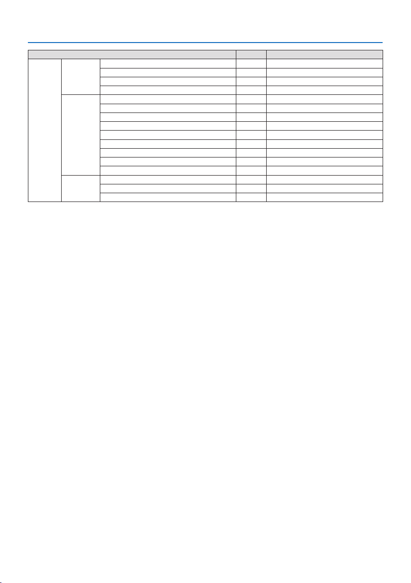
5. Using On-Screen Menu
91
MenuItemDefault Options
INFO.HDBaseT SIGNALQUALITY
OPERATIONMODE
LINKSTATUS
HDMISTATUS
Art-Net(1)Ch1
Ch2
Ch3
Ch4
Ch5
Ch6
Ch7
Ch8
Ch9
Art-Net(2)Ch10
Ch11
Ch12

5. Using On-Screen Menu
92
5-4. Menu Descriptions & Functions [INPUT]
HDMI1
This projects the video of the device connected to the HDMI 1 IN terminal.
HDMI2
This projects the video of the device connected to the HDMI 2 IN terminal.
DisplayPort
This projects the video of the device connected to the DisplayPort IN terminal.
COMPUTER
This projects the video of the device connected to the computer video input terminal.
(This projects the analog RGB signal or component signal.)
HDBaseT
Projecting the HDBaseT signal.
ENTRY LIST
Displays a list of signals. See the following pages.
TEST PATTERN
Closes the menu and switches to the test pattern screen.
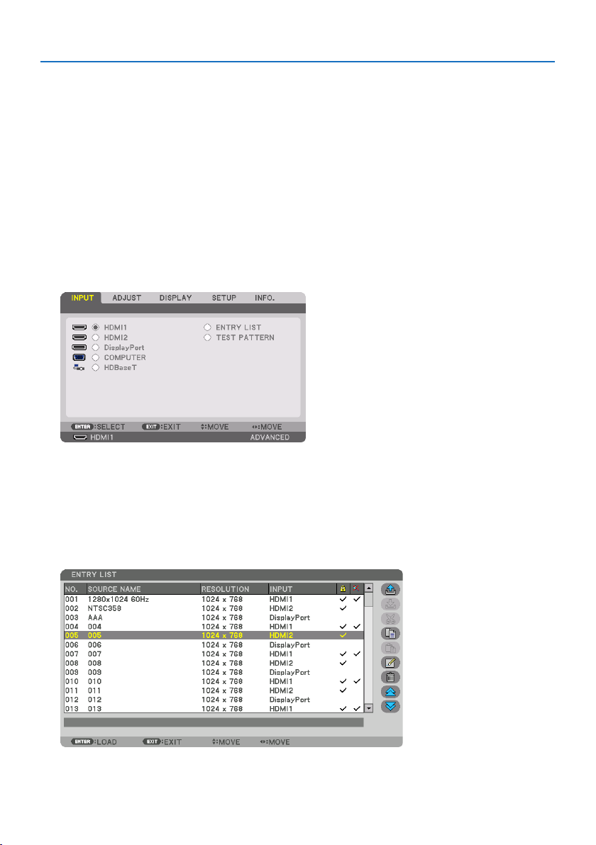
5. Using On-Screen Menu
93
Using the Entry List
When any source adjustments are made, the adjustments are automatically registered in the Entry
List. The (adjustment values of) registered signals can be loaded from the Entry List whenever
necessary.
However, only up to 100 patterns can be registered in the Entry List. When 100 patterns have been
registered in the Entry List, an error message is then displayed and no additional patterns can be
registered. You should thus delete (adjustment values of) signals that are no longer needed.
Displaying the Entry list
1. Press the MENU button.
The menu will be displayed.
2. Press the ◀ or ▶buttontoselect[INPUT].
The [INPUT] list will be displayed.
* This screen belongs to a HDBaseT model.
3. Use the ◀, ▶, ▲, or ▼toselect[ENTRY LIST] and press the ENTER button.
The [ENTRY LIST] windows will be displayed.
If the [ENTRY LIST] window is not displayed, switch the menu to [ADVANCED].
To switch the menu between [ADVANCED] and [BASIC], select [SETUP] → [CONTROL] → [TOOLS]
→ [ADMINISTRATOR MODE] → [MENU MODE]. (→ page 132)
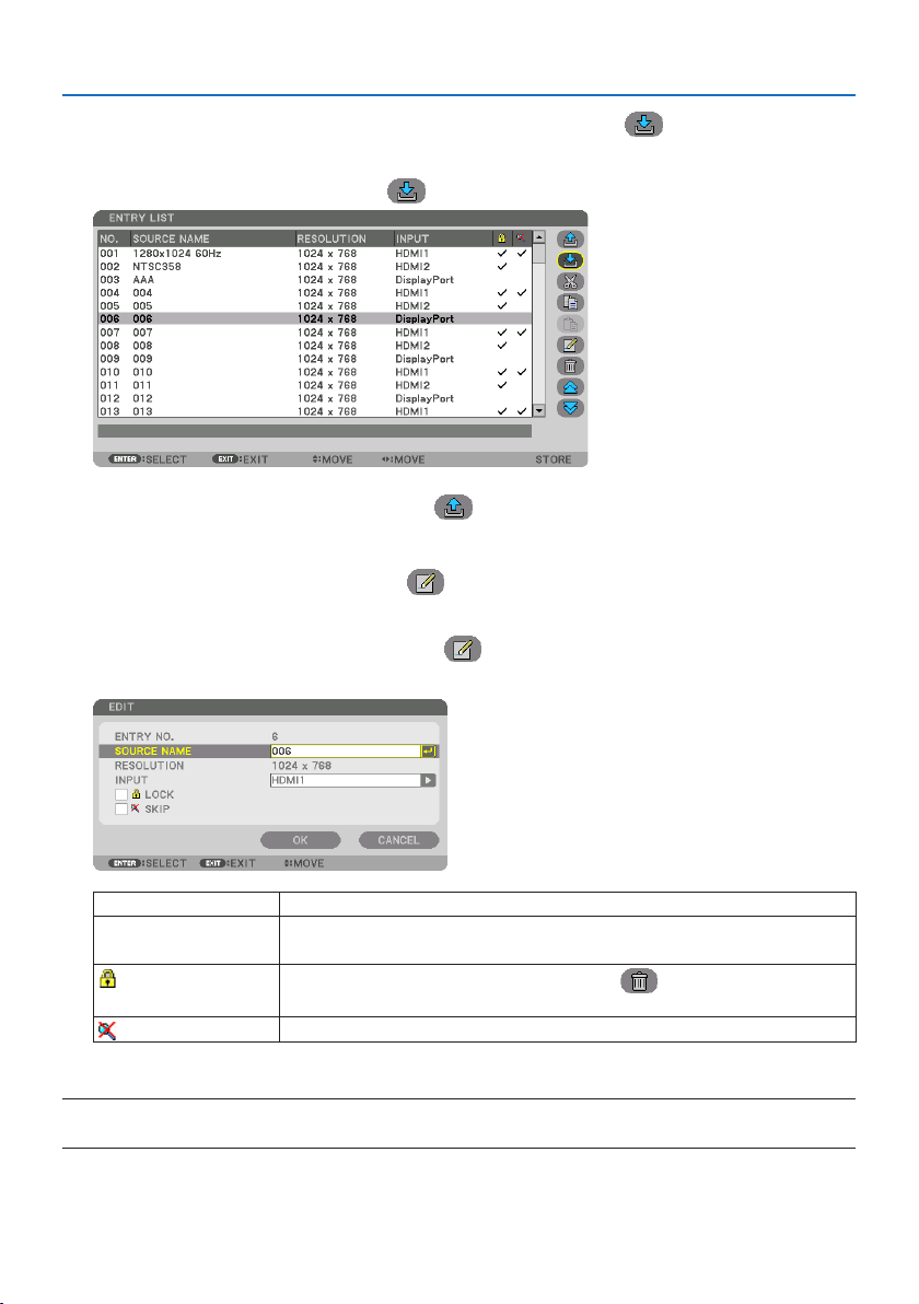
5. Using On-Screen Menu
94
EnteringthecurrentlyprojectedsignalintotheEntryList[
(STORE)]
1. Press the ▲ or ▼ button to select any number.
2. Press the ◀ or ▶buttontoselect[
(STORE)] and press the ENTER button.
CallingupasignalfromtheEntryList[ (LOAD)]
1. Press the ▲ or ▼ button to select a signal and press the ENTER button.
EditingasignalfromtheEntryList[
(EDIT)]
1. Press the ▲ or ▼ button to select a signal you wish to edit.
2. Press the ◀, ▶, ▲, or ▼buttontoselect[
(EDIT)] and press the ENTER button.
The [EDIT] window will be displayed.
SOURCENAMEEnterasignalname.Upto18alphanumericcharacterscanbeused.
INPUTTheinputterminalcanbechanged.SwitchingbetweenHDMI1/HDMI2/DisplayPort/COM-
PUTER/HDBaseTispossible.
LOCK
Setsothattheselectedsignalcannotbedeletedwhen[
(ALLDELETE)]isexecuted.The
changesmadeafterLOCKexecutioncannotbesaved.
SKIP
Setsothattheselectedsignalwillbeskippedduringautosearch.
3. Settheaboveitemsandselect[OK] and press the ENTER button.
NOTE:
•Theinputterminalcannotbechangedtothecurrentlyprojectedsignal.
5. Using On-Screen Menu
95
CuttingasignalfromtheEntryList[
(CUT)]
1. Press the ▲ or ▼ button to select a signal you wish to delete.
2. Press the ◀, ▶, ▲, or ▼buttontoselect[
(CUT)] and press the ENTER button.
The signal will be deleted from the Entry List and the deleted signal will be displayed on the
clipboard at the bottom of the Entry List.
NOTE:
•Thecurrentlyprojectedsignalcannotbedeleted.
•Whenthelockedsignalisselected,itwillbedisplayedingraywhichindicatesitisnotavailable.
TIP:
•DataontheclipboardcanbepassedontotheEntryList.
•DataontheclipboardwillnotbelostaftertheEntryListisclosed.
CopyingandpastingasignalfromtheEntryList[
(COPY)]/[ (PASTE)]
1. Press the ▲ or ▼ button to select a signal you wish to copy.
2. Press the ◀, ▶, ▲, or ▼buttontoselect[
(COPY)] and press the ENTER button.
The copied signal will be displayed on the clipboard at the bottom of the Entry List.
3. Press the ◀ or ▶ button to move to the list.
4. Press the ▲ or ▼ button to select a signal.
5. Press the ◀, ▶, ▲, or ▼buttontoselect[
(PASTE)] and press the ENTER button.
Data on the clipboard will be pasted to the signal.
DeletingallthesignalsfromtheEntryList[
(ALL DELETE)]
1. Press the ◀, ▶, ▲, or ▼buttontoselect[
(ALL DELETE)] and press the ENTER button.
The confirmation message will be displayed.
2. Press the ◀ or ▶buttontoselect[YES] and press the ENTER button.
NOTE:
•Thelockedsignalcannotbedeleted.
Using Test Pattern [TEST PATTERN]
Displays the test pattern for adjusting distortion on the screen and the focus at the time of the pro-
jector setup. Once the [TEST PATTERN] on the onscreen menu is selected, the pattern for adjustment
will be displayed on. If you find distortion on the pattern, adjust the projector installation angle
or correct distortion by pressing the Geometric. button on the remote. If the focus adjustment is
required, press the FOCUS button on the remote control for displaying the [FOCUS] adjustment
screen and then adjust [FOCUS] by ◀ or ▶ button. Recommend to perform the focus adjustment
after leaving the projector under the state the TEST PATTERN has been projected for over 30 minutes.
Press EXIT button to close the test pattern and return to the menu.
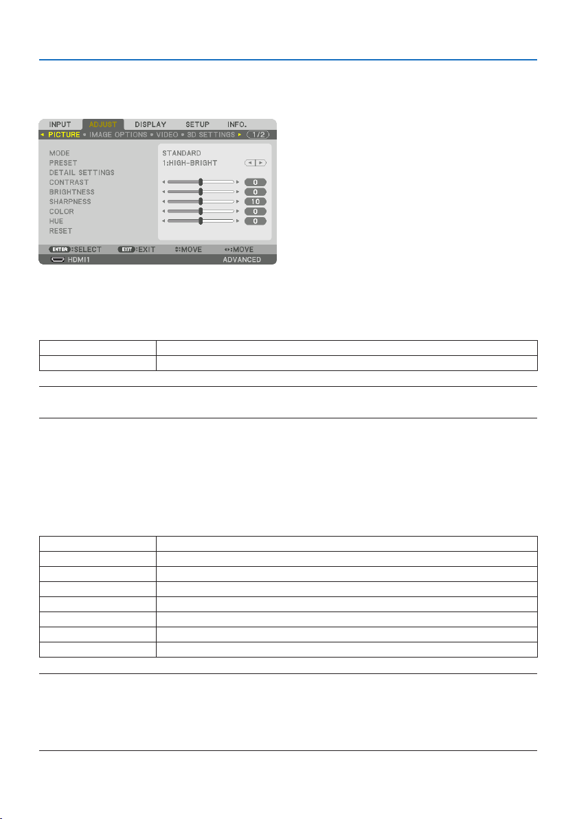
5. Using On-Screen Menu
96
5-5. Menu Descriptions & Functions [ADJUST]
[PICTURE]
[MODE]
This function allows you to determine how to save settings for [DETAIL SETTINGS] of [PRESET] for
each input.
STANDARDSavessettingsforeachitemof[PRESET](Preset1through7)
PROFESSIONALSavesallthesettingsof[PICTURE]foreachinput.
NOTE:
•When[TESTPATTERN]isdisplayed,[MODE]cannotbeselected.
[PRESET]
This function allows you to select optimized settings for your projected image.
You can adjust neutral tint for yellow, cyan or magenta.
There are seven factory presets optimized for various types of images. You can also use [DETAIL
SETTINGS] to set user adjustable settings to customize each gamma or color.
Your settings can be stored in [PRESET] 1 to [PRESET] 7.
AUTOAutomaticallydistinguishtheoptimalsettingfortheinputsignal.
HIGH-BRIGHTRecommendedforuseinabrightlylitroom.
PRESENTATIONRecommendedformakingapresentationusingaPowerPointle.
VIDEORecommendedfortypicalTVprogramviewing.
MOVIERecommendedformovies.
GRAPHICRecommendedforgraphics.
sRGBStandardcolorvalues
DICOMSIM.RecommendedforDICOMsimulationformat.
NOTE:
•The[DICOMSIM.]optionisfortraining/referenceonlyandshouldnotbeusedforactualdiagnosis.
•DICOMstandsforDigitalImagingandCommunicationsinMedicine.ItisastandarddevelopedbytheAmericanCollegeofRadiology
(ACR)andtheNationalElectricalManufacturersAssociation(NEMA).
Thestandardspecieshowdigitalimagedatacanbemovedfromsystemtosystem.
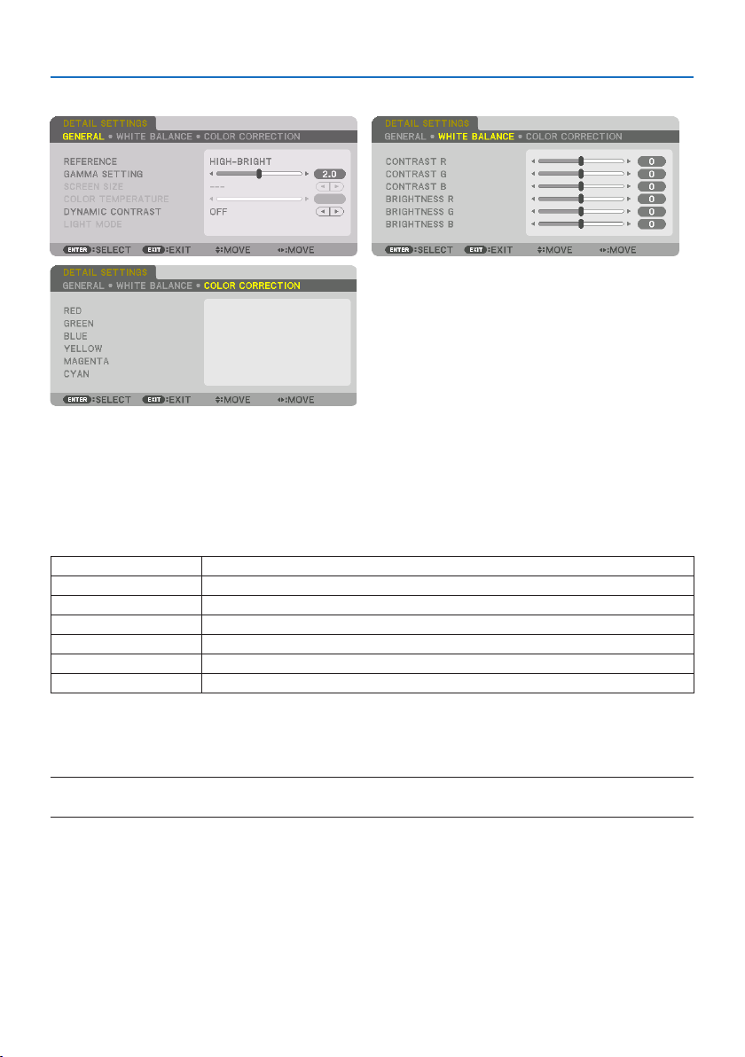
5. Using On-Screen Menu
97
[DETAIL SETTINGS]
[GENERAL]
StoringYourCustomizedSettings[REFERENCE]
This function allows you to store your customized settings in [PRESET 1] to [PRESET 7].
First, select a base preset mode from [REFERENCE], then set [GAMMA SETTING] and [COLOR TEM-
PERATURE].
HIGH-BRIGHTRecommendedforuseinabrightlylitroom.
PRESENTATIONRecommendedformakingapresentationusingaPowerPointle.
VIDEORecommendedfortypicalTVprogramviewing.
MOVIERecommendedformovies.
GRAPHICRecommendedforgraphics.
sRGBStandardcolorvalues.
DICOMSIM.RecommendedforDICOMsimulationformat.
Adjustingthegradationofthepicture[GAMMA SETTING]
Adjusts the gradation of the picture. With this, even dark areas can be reproduced vividly.
NOTE:
•Thisfunctionisnotavailablewhen[DICOMSIM.]isselectedfor[DETAILSETTINGS].

5. Using On-Screen Menu
98
SelectingScreenSizeforDICOMSIM[SCREEN SIZE]
This function will perform gamma correction appropriate for the screen size.
LARGEForscreensizeof300"
MEDIUMForscreensizeof200"
SMALLForscreensizeof100"
NOTE:
•Thisfunctionisavailableonlywhen[DICOMSIM.]isselectedfor[DETAILSETTINGS].
AdjustingColorTemperature[COLOR TEMPERATURE]
This option allows you to select the color temperature of your choice.
A value between 5000 K and 10500 K can be set in 100 K units.
NOTE:
•When[HIGH-BRIGHT]isselectedin[REFERENCE],thisfunctionisnotavailable.
AdjustingBrightnessandContrast[DYNAMIC CONTRAST]
When set, the most optimal contrast ratio is adjusted according to the video.
OFFDynamiccontrastisdisabled.
MOTIONIMAGEMostoptimalsettingsformovingimages.
STILLIMAGEMostoptimalsettingsforstaticimages.Rapidlyfollowsanychangesinthevideo.
NOTE:
•[DYNAMICCONTRAST]cannotbeselectedinthefollowingcases.[]
-Whenthe[REF.LIGHTMODE]issetto[ECO2]
-Whentheinputterminalisselectedfor[SUBINPUT]under[PIP/PICTUREBYPICTURE]
-Whenperforming[GEOMETRICCORRECTION]
-When[EDGEBLENDING] →[MODE]issetto[ON]
-When[PICTURESETTING] →[MODE]issetto[ZOOM]or[TILING]
-When[MULTISCREEN] →[WHITEBALANCE] →[MODE]issetto[ON]
-When[FANMODE]issetto[HIGH]or[HIGHALTITUDE]
-Whenperformingportraitprojection
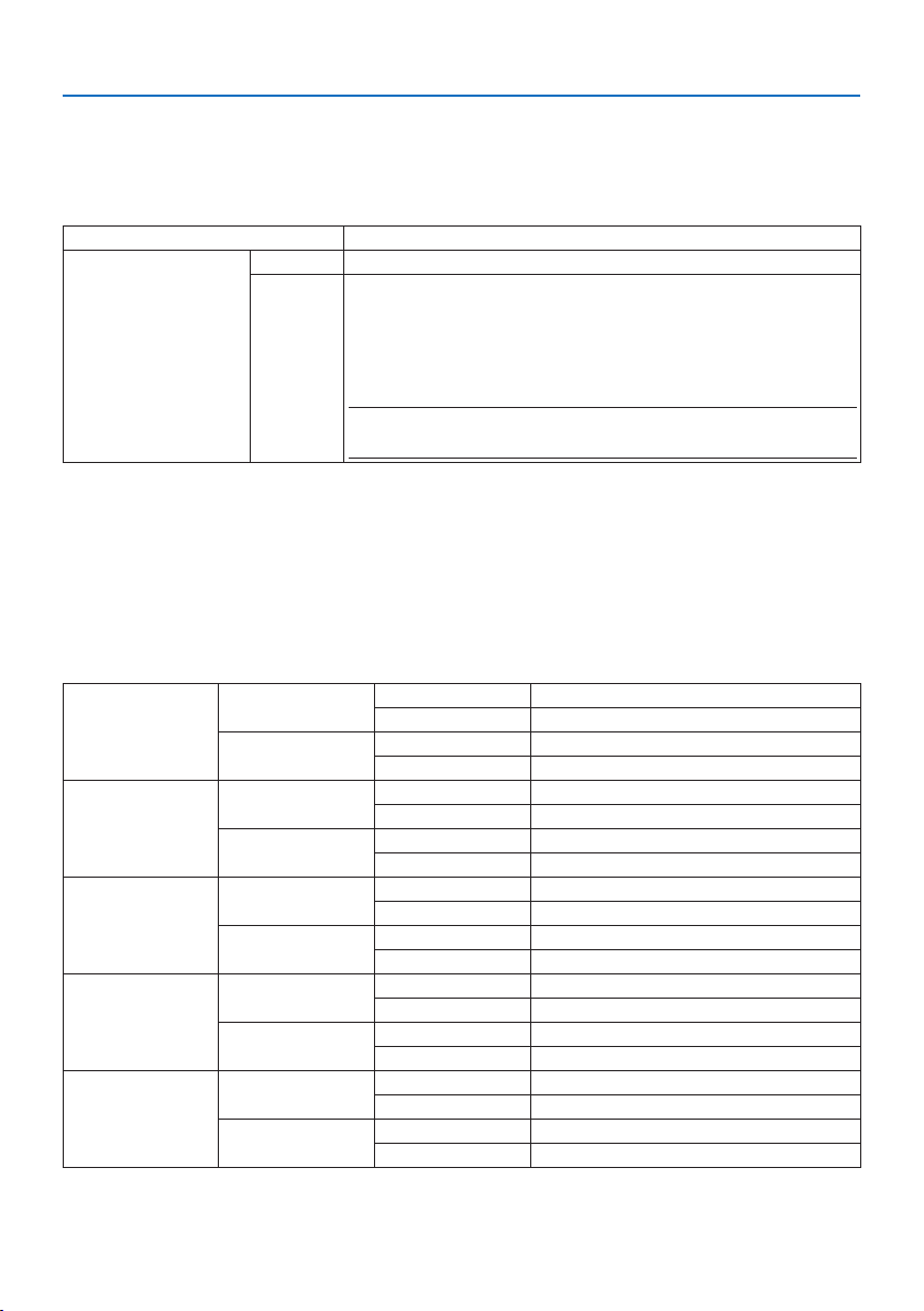
5. Using On-Screen Menu
99
AdjustingBrightness[LIGHT MODE]
Adjust the brightness of the projector and save it for each input signal.
With the [REF. LIGHT MODE] set to [NORMAL], the adjustment will be valid if the [PICTURE] → [MODE]
is set to [PROFESSIONAL]. (→ page
96, 128)
LIGHTADJUSTBrightnesscanbeadjustedin1%incrementsfrom50to100%.
CONSTANTBRIGHTNESSOFF[CONSTANTBRIGHTNESS]modewillbecanceled.
ON Maintainsthebrightnessthatisineectatthetime[ON]isselected.Unless[OFF] is
selected,thesamesettingswillremainineectevenwhentheprojectoristurned
o.
•Tore-adjustthebrightness,rstturnthissetting[OFF]beforemakingfurther
adjustments.
NOTE:
•The[CONSTANTBRIGHTNESS]settingwillnotbesavedforeachinputsignal.
AdjustingWhiteBalance[WHITE BALANCE]
This allows you to adjust the white balance. Contrast for each color (RGB) to adjust the white level
of the screen; Brightness for each color (RGB) is used to adjust the black level of the screen.
[COLOR CORRECTION]
Corrects the color for all signals.
Adjusts the tone for the colors red, green, blue, yellow, magenta and cyan.
RED HUE + Direction Magentadirection
− Direction Yellowdirection
SATURATION+ Direction Vivid
− Direction Weak
GREENHUE + Direction Yellowdirection
− Direction Cyandirection
SATURATION+ Direction Vivid
− Direction Weak
BLUE HUE + Direction Cyandirection
− Direction Magentadirection
SATURATION+ Direction Vivid
− Direction Weak
YELLOWHUE + Direction Reddirection
− Direction Greendirection
SATURATION+ Direction Vivid
− Direction Weak
MAGENTAHUE + Direction Bluedirection
− Direction Reddirection
SATURATION+ Direction Vivid
− Direction Weak

5. Using On-Screen Menu
100
CYANHUE + Direction Greendirection
− Direction Bluedirection
SATURATION+ Direction Vivid
− Direction Weak
[CONTRAST]
Adjusts the intensity of the image according to the incoming signal.
[BRIGHTNESS]
Adjusts the brightness level or the back raster intensity.
[SHARPNESS]
Controls the detail of the image.
[COLOR]
Increases or decreases the color saturation level.
[HUE]
Varies the color level from +/− green to +/− blue. The red level is used as reference.
NOTE:
•When[TESTPATTERN]isdisplayed,[CONTRAST],[BRIGHTNESS],[SHARPNESS],[COLOR]and[HUE]cannotbeadjusted.
[RESET]
The settings and adjustments for [PICTURE] will be returned to the factory default settings with the
exception of the following; Preset numbers and [REFERENCE] within the [PRESET] screen.
The settings and adjustments under [DETAIL SETTINGS] within the [PRESET] screen that are not
currently selected will not be reset.
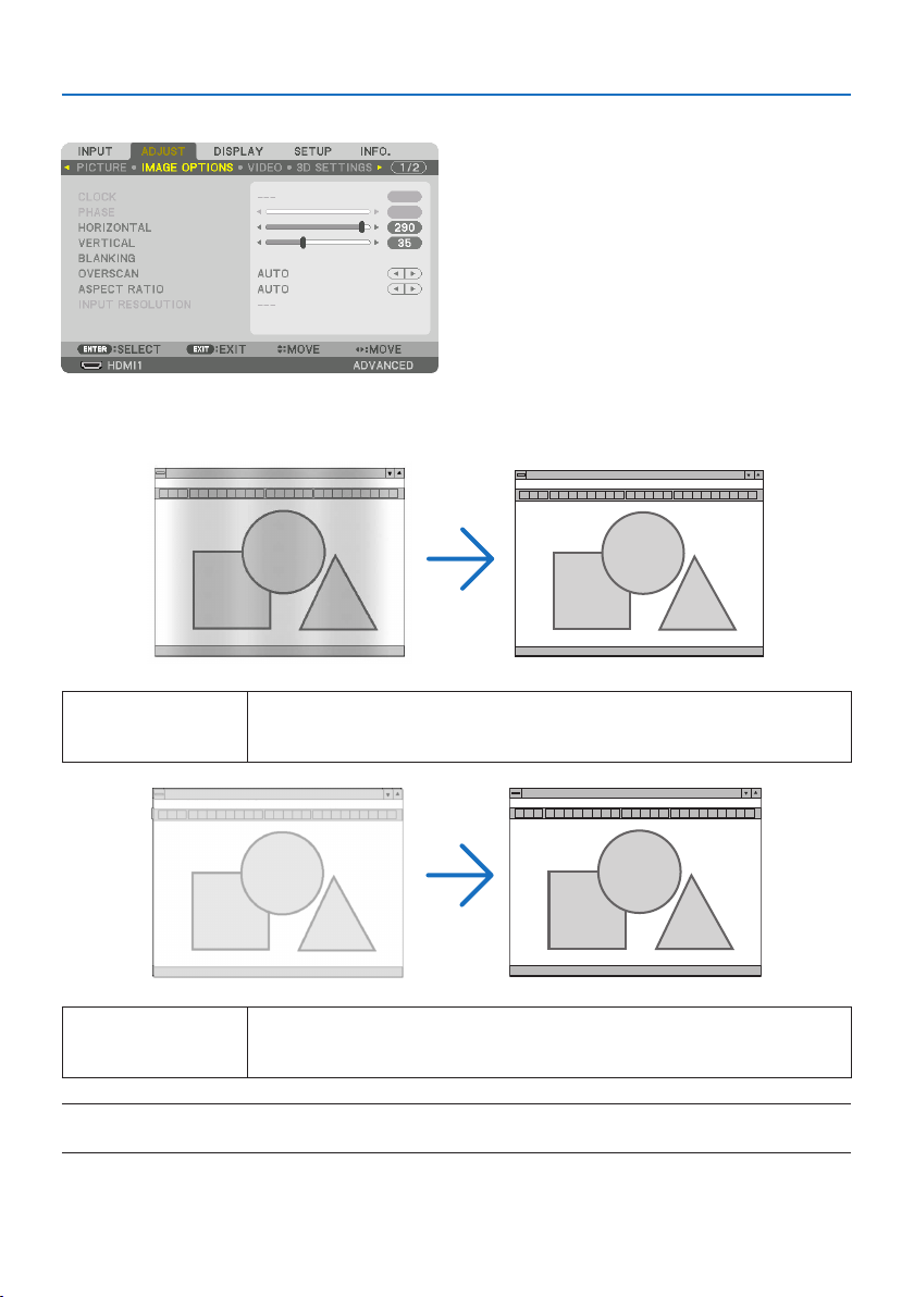
5. Using On-Screen Menu
101
[IMAGE OPTIONS]
AdjustingClockandPhase[CLOCK/PHASE]
This allows you to manually adjust [CLOCK] and [PHASE].
CLOCKUsethisitemtonetunethecomputerimageortoremoveanyverticalbandingthatmightappear.
Thisfunctionadjuststheclockfrequenciesthateliminatethehorizontalbandingintheimage.
Thisadjustmentmaybenecessarywhenyouconnectyourcomputerforthersttime.
PHASEUsethisitemtoadjusttheclockphaseortoreducevideonoise,dotinterferenceorcrosstalk.(This
isevidentwhenpartofyourimageappearstobeshimmering.)
Use[PHASE]onlyafterthe[CLOCK]iscomplete.
NOTE:
•The[CLOCK]and[PHASE]itemsareavailableforRGBsignalsonly.
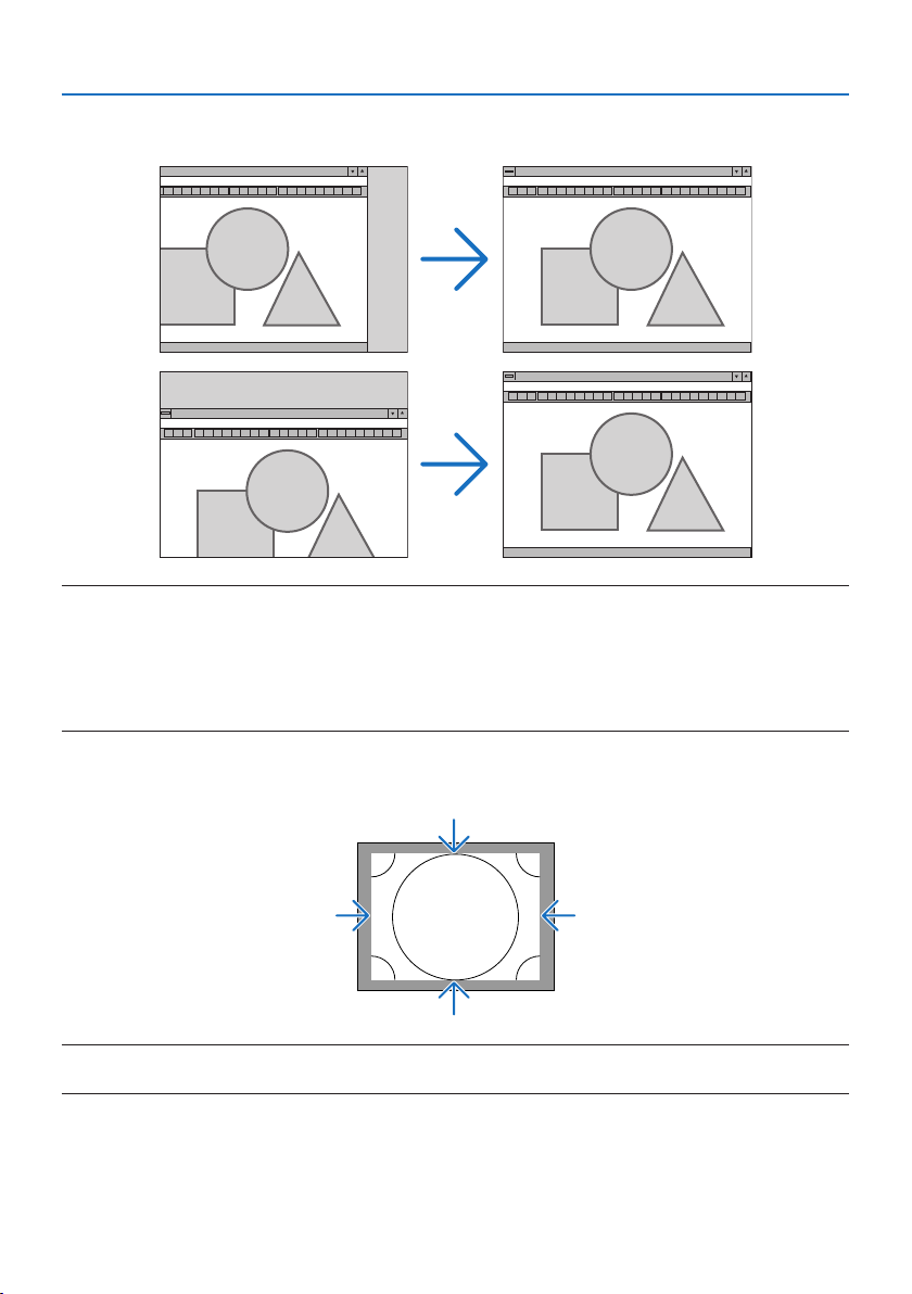
5. Using On-Screen Menu
102
Adjusting Horizontal/Vertical Position [HORIZONTAL/VERTICAL]
Adjusts the image location horizontally and vertically.
NOTE:
•Animagecanbedistortedduringtheadjustmentof[CLOCK]and[PHASE].Thisisnotmalfunction.
•Theadjustmentsfor[CLOCK],[PHASE],[HORIZONTAL],and[VERTICAL]willbestoredinmemoryforthecurrentsignal.Thenexttime
youprojectthesignalwiththesameresolution,horizontalandverticalfrequency,itsadjustmentswillbecalledupandapplied.
Todeleteadjustmentsstoredinmemory,fromthemenu,youselect[SETUP] →[RESET] →[CURRENTSIGNAL]andresetthe
adjustments.
[BLANKING]
Adjusts the display range (blanking) at the top, bottom, left and right edges of the input signal.
NOTE:
•Thiscanbesetwhen[3DSETTINGS] →[FORMAT]issetto[OFF(2D)].

5. Using On-Screen Menu
103
SelectingOverscanPercentage[OVERSCAN]
Select overscan percentage (Auto, 0%, 5% and 10%) for signal.
Projected image
Overscaned by 10%
NOTE:
•The[OVERSCAN]itemisnotavailable:
-when[NATIVE]isselectedfor[ASPECTRATIO].
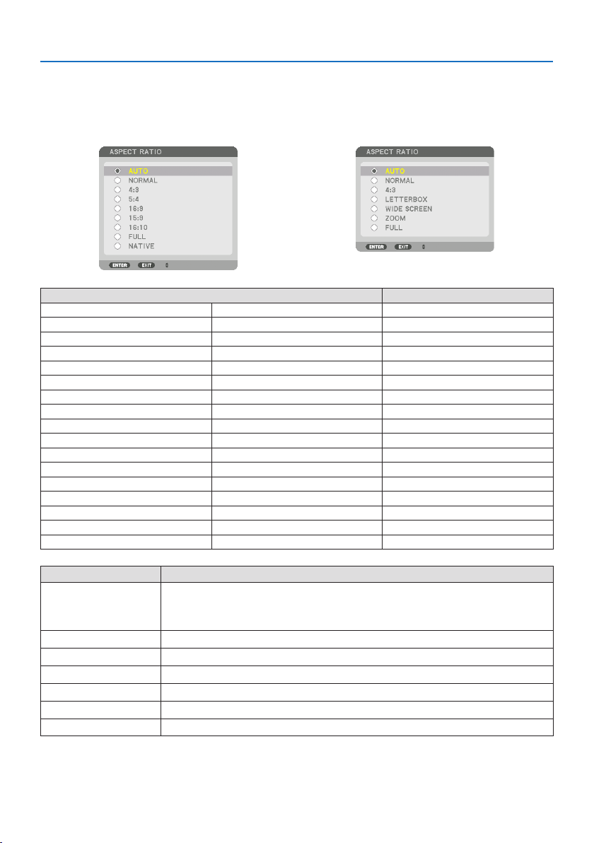
5. Using On-Screen Menu
104
SelectingtheAspectRatio[ASPECT RATIO]
Usethisfunctiontoselectthescreen’slateral:longitudinalaspectratio.
The projector automatically identifies the signal being input and sets the optimum aspect ratio.
For Computer signal For HDTV/SDTV signals
Resolution Aspect Ratio
VGA 640×4804:3
SVGA 800×6004:3
XGA 1024×7684:3
WXGA 1280×76815:9
WXGA 1280×80016:10
HD(FWXGA) 1366×768approx.16:9
WXGA+ 1440×90016:10
SXGA 1280×10245:4
SXGA+ 1400×10504:3
WXGA++ 1600×90016:9
UXGA 1600×12004:3
WSXGA+ 1680×105016:10
FHD(1080P) 1920×108016:9
WUXGA 1920×120016:10
WQXGA 2560×160016:10
Quad HD 3840×216016:9
Quad HD 4096×216019:7
Options Function
AUTOTheprojectorwillautomaticallydeterminetheincomingsignalanddisplayitinitsaspectratio.
Theprojectormayerroneouslydeterminetheaspectratiodependingonitssignal.Ifthisoccurs,
selecttheappropriateaspectratiofromthefollowing.
NORMALTheimageisdisplayedinitsoriginalaspectratioofitsinputsignal.
4:3Theimageisdisplayedin4:3aspectratio.
5:4Theimageisdisplayedin5:4aspectratio
16:9 Theimageisdisplayedin16:9aspectratio
15:9 Theimageisdisplayedin15:9aspectratio
16:10 Theimageisdisplayedin16:10aspectratio
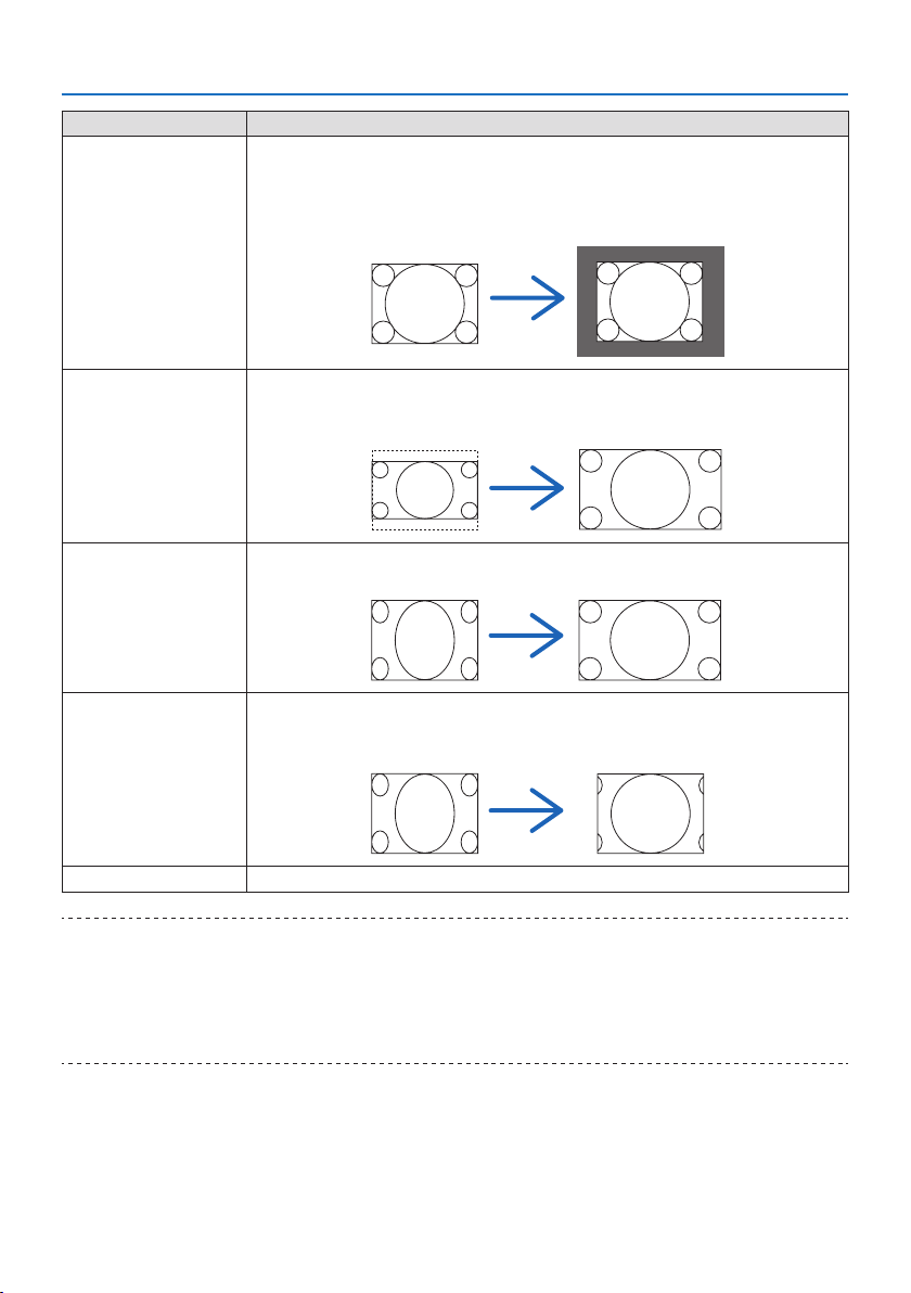
5. Using On-Screen Menu
105
Options Function
NATIVETheprojectordisplaysthecurrentimageinitstrueresolutionwhentheincomingcomputersignal
hasalowerorhigherresolutionthantheprojector’snativeresolution.(→ page
182)
Whentheincomingcomputersignalhasahigherresolutionthantheprojector’snativeresolution,
thecenterofanimagewillbedisplayed.
4:3
LETTERBOX Theimageofaletterboxsignal(16:9)isstretchedequallyinthehorizontalandverticaldirections
totthescreen.
LETTERBOX
WIDESCREENTheimageofasqueezesignal(16:9)isstretchedleftandrightin16:9.
Squeeze
ZOOM Theimageofasqueezesignal(16:9)isstretchedleftandrightin4:3.
Partsofthedisplayedimagearecroppedattheleftandrightedgesandthereforenotvisible.
Squeeze
FULLProjecttofullscreensize.
TIP:
•Imagepositioncanbeadjustedverticallyusing[POSITION]whenthe[16:9],[15:9],or[16:10]aspectratiosareselected.
•Theterm“letterbox”referstoamorelandscape-orientedimagewhencomparedtoa4:3image,whichisthestandardaspectratio
foravidesource.
Theletterboxsignalhasaspectratioswiththevistasize“1.85:1”orcinemascopesize“2.35:1”formovielm.
•Theterm“squeeze”referstothecompressedimageofwhichaspectratioisconvertedfrom16:9to4:3.
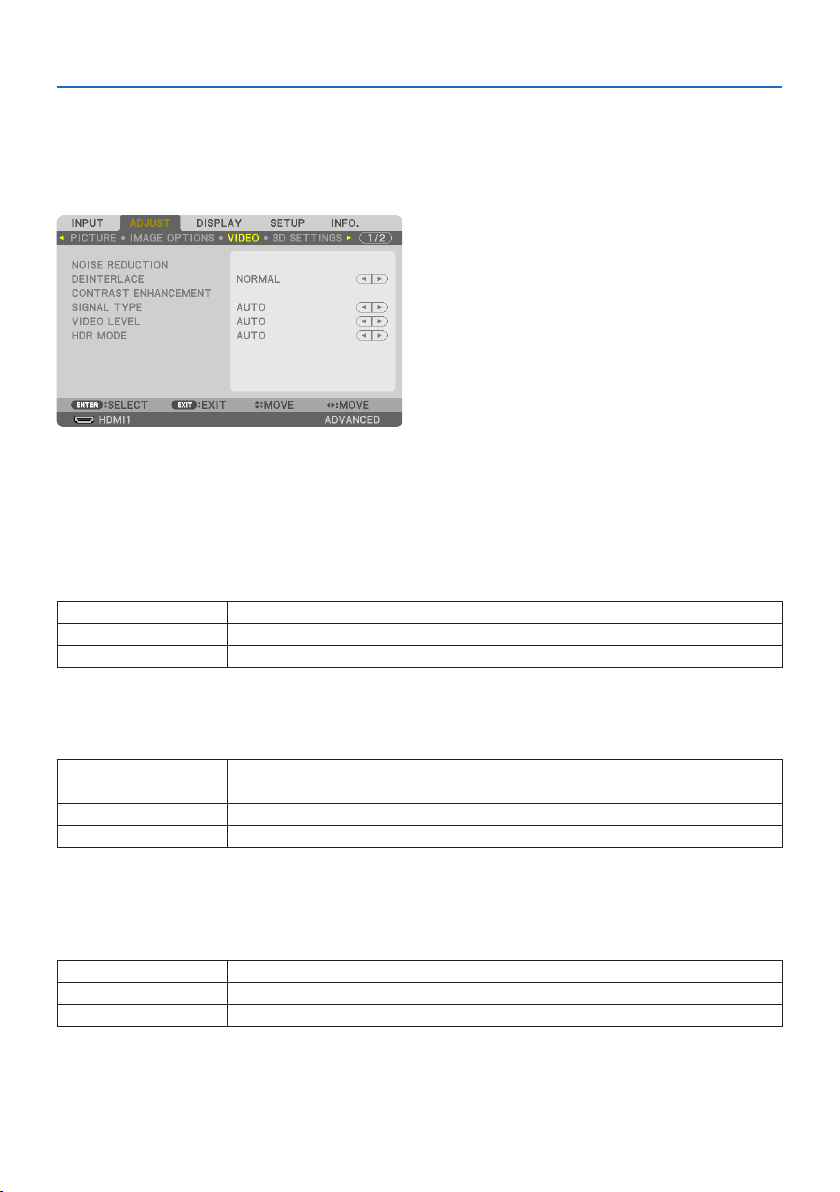
5. Using On-Screen Menu
106
[INPUT RESOLUTION]
The resolution is assigned automatically when the resolution of the input signal from the computer
video input terminal (analog RGB) cannot be distinguished.
[VIDEO]
UsingNoiseReduction[NOISE REDUCTION]
When projecting a video image, you can use the [NOISE REDUCTION] function to reduce the screen
noise (roughness and distortion). This device is equipped with three types of noise reduction func-
tions. Select the function according to the type of noise. Depending on the noise level, the noise
reduction effect can be set to [OFF], [LOW ], [MEDIUM] or [HIGH]. [NOISE REDUCTION] can be selected
for SDTV, HDTV signal and component signal input.
RANDOMNRReducesickeringrandomnoiseinanimage.
MOSQUITONRReducesmosquitonoisethatappearsaroundtheedgesofanimageduringBlu-rayplayback.
BLOCKNRReducesblocknoiseormosaic-likepatterns.
SelectingInterlacedProgressiveConversionProcessMode[DEINTERLACE]
This function allows you to select an interlaced-to-progressive conversion process for video signals.
NORMALAutomaticallydistinguishesamovingimagefromastaticimagetocreateadistinctimage.Please
select[MOVIE]ifthereareanyobviousjitterandnoises.
MOVIESelectwhenprojectingmovingimages.Thisissuitableforsignalswithalotofjitterandnoise.
STILLSelectwhenprojectingstaticimages.Thevideowillickerwhenamovingimageisprojected.
[CONTRAST ENHANCEMENT]
Using the characteristics of the human eye, a picture quality with a sense of contrast and resolution
is achieved.
OFF[CONTRASTENHANCEMENT]functionisdisabled.
AUTOContrastandpicturequalityareautomaticallyimprovedusingthisfunction.
NORMALAdjustthegainmanually.

5. Using On-Screen Menu
107
[SIGNAL TYPE]
Selection of RGB and component signals. Normally, this is set to [AUTO]. Please change the setting
if the color of the image remains unnatural.
AUTOAutomaticallydistinguishesRGBandcomponentsignals.
RGBSwitchestotheRGBinput.
REC601 SwitchestothecomponentsignalconformingtotheITU-RRec601standard.
SettingappropriatetoSDTVimages.
REC709 SwitchestothecomponentsignalconformingtotheITU-RRec709standard.
SettingappropriatetoHi-Visionimages.
REC2020 SwitchestothecomponentsignalconformingtotheITU-RRec2020standard.
Settingappropriateto4Kimages.
[VIDEO LEVEL]
Selection of the video signal level when connecting an external device to the HDMI 1 IN terminal,
HDMI 2 IN terminal, DisplayPort input terminal, and HDBaseT IN terminal of the projector.
AUTOThevideolevelisswitchedautomaticallybasedontheinformationfromthedeviceoutputtingthe
signal.
Dependingontheconnecteddevice,thissettingmaynotbemadeproperly.Inthiscase,switchto
[NORMAL]or[ENHANCED]fromthemenuandviewwiththeoptimumsetting.
NORMALThisdisablestheenhancedmode.
ENHANCEDThisimprovestheimage’scontrast,expressingthedarkandlightsectionsmoredynamically.
SUPERWHITEThevideocontrastisimprovedandthedarkareasappearmoredynamic.
[HDR MODE]
AUTOAutomaticallydistinguishesHDRsignal.
OFFProjectstheimagebasedontheinputsignal
ON ProjectstheimageconformingtotheHDRsignal
NOTE:
•Theseoptionsareavailableexclusivelyfor4Ksignal.
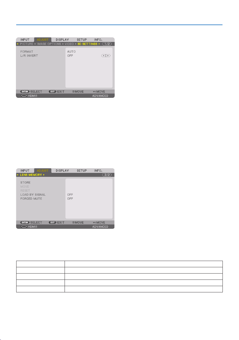
5. Using On-Screen Menu
108
[3D SETTINGS]
[FORMAT]
Select the 3D video format (recording / transmission format). Select to match the 3D broadcast
and 3D media. Normally, [AUTO] is selected. Please select the 3D input signal format when the 3D
detection signal of the format cannot be distinguished.
[L/R INVERT]
Invert the display order of the left and right videos.
Select [ON] if you feel uncomfortable with the 3D display when [OFF] is selected.
Using the Lens Memory Function [LENS MEMORY]
This function serves to store the adjusted values for each input signal when using the [LENS SHIFT],
motorized [ZOOM], and motorized [FOCUS] functions of the projector. Adjusted values can be ap-
plied to the signal you selected. This will eliminate the need to adjust lens shift, focus, and zoom
at the time of source selection.
STOREStoresthecurrentadjustedvaluesinmemoryforeachinputsignal.
MOVE Appliestheadjustedvaluestothecurrentsignal.
RESETReturnstheadjustedvaluestothelastcondition.
LOADBYSIGNALMovesthelenstotheregisteredlensadjustmentpositionwhenthesignalisswitched.
FORCEDMUTESelectwhethertomutethepictureornotwhenmovingthelens.
•ThisfunctionisnotavailableforthelensunitNP44ML.
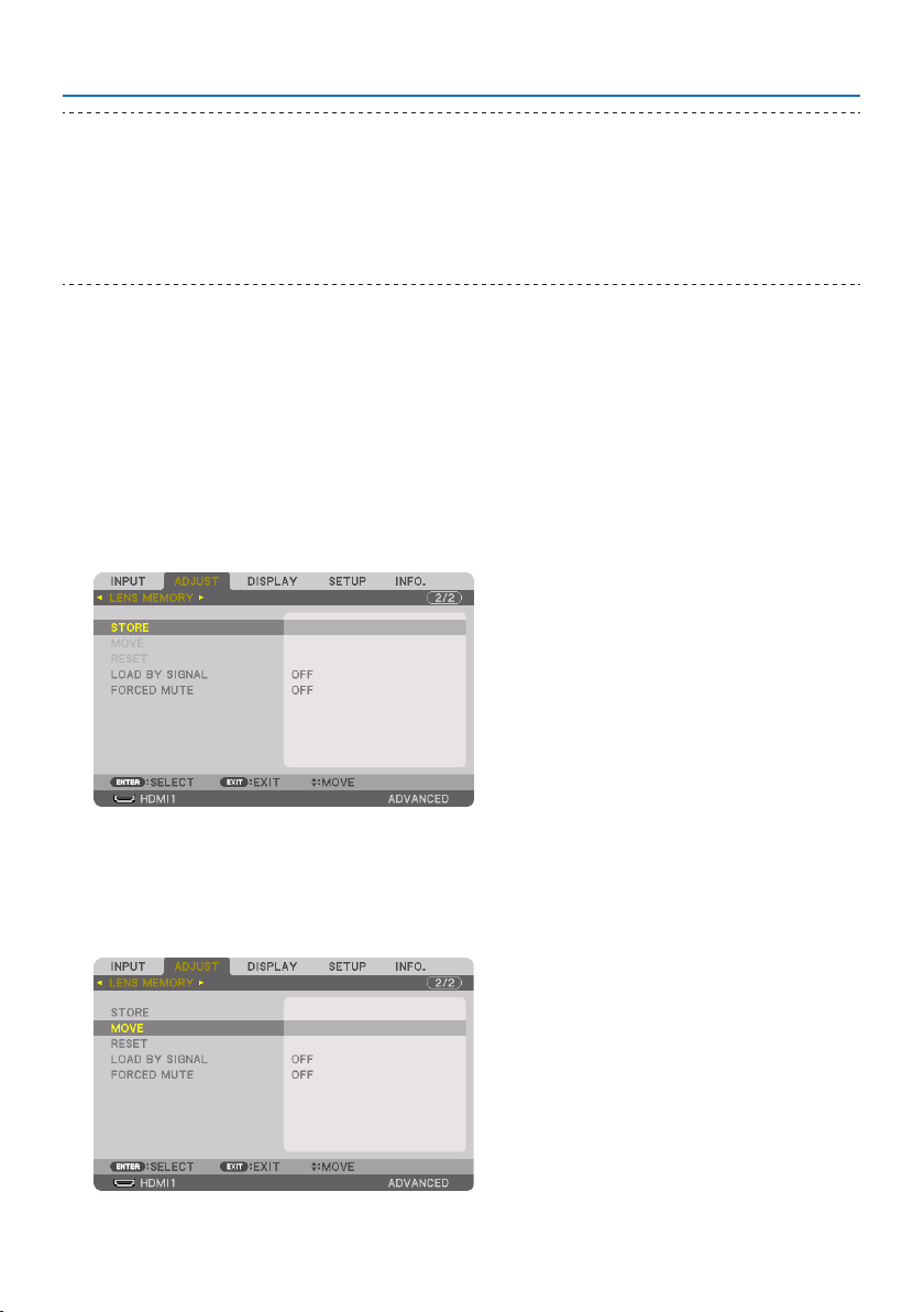
5. Using On-Screen Menu
109
TIP:
•Lensmemoryadjustmentswillbeautomaticallyregisteredthe[ENTRYLIST].Theselensmemoryadjustmentscanbeloadedfrom
the[ENTRYLIST].(→ page 93)
Notethatperforming[CUT]or[ALLDELETE]inthe[ENTRYLIST]willdeletelensmemoryadjustmentsaswellassourceadjustments.
Thisdeletionwillnottakeeectuntilotheradjustmentsisloaded.
•Forstoringeachadjustmentof[LENSSHIFT],motorized[ZOOM],andmotorized[FOCUS]ascommonvalueforallinputsignal,store
themas[REF.LENSMEMORY].
Tostoreyouradjustedvaluesin[LENS MEMORY]:
1. Project the connected device signal you want to adjust.
2. Adjust the projecting image of position, size and focus by the SHIFT/HOME POSITION,
ZOOM +/−, and FOCUS +/− buttons.
•Adjustmentcanbeperformedbytheremotecontrol.Pleasereferto“2-5Adjustingthe
Picture Size and Position” on page
26.
•Slightadjustmentbymovingtheprojectorpositionandbythetiltfootisnotsubjectof
[LENS MEMORY].
3. Movethecursoron[STORE] and press ENTER.
4. Movethecursoron[YES] and press ENTER.
Tocalluptheadjustedvaluesfrom[LENS MEMORY]:
1. Fromthemenu,select[ADJUST] →[LENS MEMORY] →[MOVE] and press the ENTER but-
ton.
The confirmation screen will be displayed.
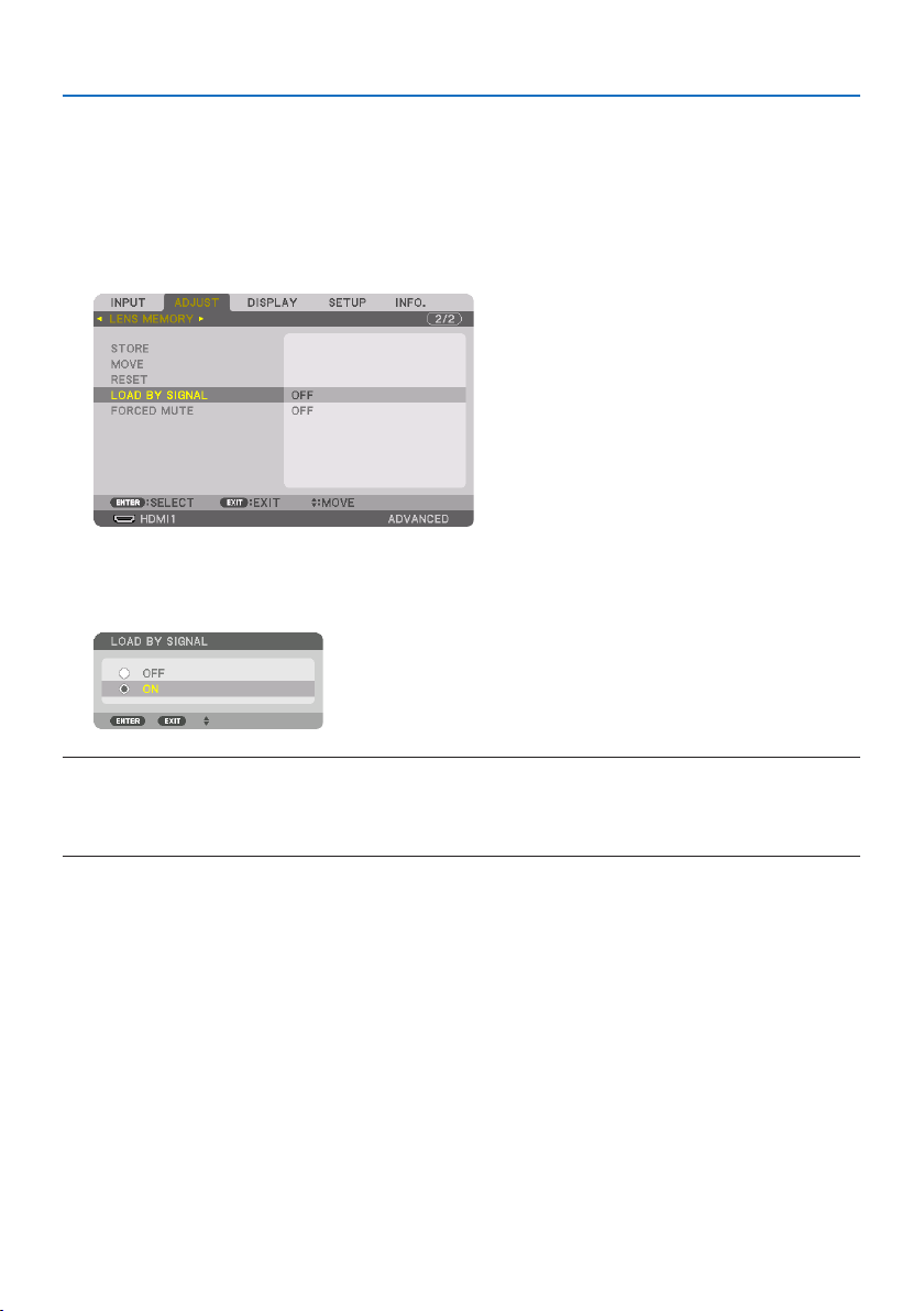
5. Using On-Screen Menu
110
2. Press the ◀buttontoselectand[YES] and press the ENTER button.
During projection, if the adjusted values for an input signal have been saved, the lens will shift.
If not, the lens will shift according to the adjusted values stored in the selected [REF. LENS
MEMORY] → [PROFILE] number.
To automatically apply the adjusted values at the time of source selection:
1. Fromthemenu,select[LOAD BY SIGNAL] and press the ENTER button.
2. Press the ▼buttontoselectand[ON] and press the ENTER button.
This will move the lens automatically to the position at the time of source selection according
to the adjusted values.
NOTE:
•The[LENSMEMORY]functionmaynotproduceacompletelyalignedimage(duetotolerancesinthelenses)usingtheadjusted
valuesstoredintheprojector.Aftercallingupandapplyingtheadjustedvaluesfromthe[LENSMEMORY]function,nelyadjust
the[LENSSHIFT],[ZOOM]and[FOCUS]toproducethebestpossibleimage.
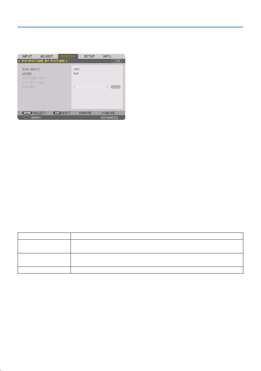
5. Using On-Screen Menu
111
5-6. Menu Descriptions & Functions [DISPLAY]
[PIP/PICTURE BY PICTURE]
SUB INPUT
Select the input signal to be displayed in the sub-display.
Please refer to “4-2. Using a single projector to project two types of videos at the same time [PIP/
PICTURE BY PICTURE]” (→ page
67) for details on the operation.
MODE
Select either [PIP] (PICTURE IN PICTURE) or [PICTURE BY PICTURE] when switching to 2-screen display.
PICTURE SWAP
The videos in the main display and sub-display will be switched.
Please refer to “4-2. Using a single projector to project two types of videos at the same time [PIP/
PICTURE BY PICTURE]” (→ page
67) for details.
PIP SETTING
Select the display position, position adjustment and size of the sub-display in the [PIP] screen.
STARTPOSITIONSelectionofthedisplaypositionofthesub-displaywhenswitchingtothe[PIP]screen.
HORIZONTALPOSITIONAdjustthedisplaypositionofthesub-displayinthehorizontaldirection.Therespectivecornerswill
serveasreferencepoints.
VERTICALPOSITIONAdjustthedisplaypositionofthesub-displayintheverticaldirection.Therespectivecornerswill
serveasreferencepoints.
SIZESelectthedisplaysizeofthesub-display.
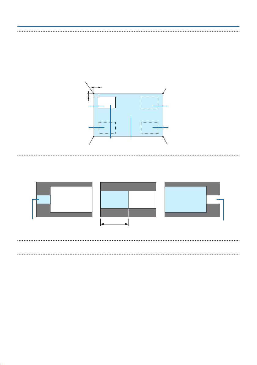
5. Using On-Screen Menu
112
TIP:
•The[HORIZONTALPOSITION]and[VERTICALPOSITION]aretheamountofmovementfromthereferencepoints.Forexample,when
[TOP-LEFT]isadjusted,thepositionisdisplayedwiththesameamountofmovementevenifdisplayedwithother[STARTPOSITION]
settings.
Themaximumamountofmovementishalftheresolutionoftheprojector.
Reference point
Adjust using the
horizontal position
Sub-displayMaindisplay
Reference point
Adjust using the vertical posi-
tion
TOP-LEFT TOP-RIGHT
BOTTOM-LEFT BOTTOM-RIGHT
Reference pointReference point
BORDER
Select the display boundary of the main display and sub-display of the [PICTURE BY PICTURE] screen.
Display boundary
Maindisplay
Sub-display
Maindisplay
Sub-displayMaindisplaySub-display
TIP:
•Sevenoptionsfromzerotosixareavailable.
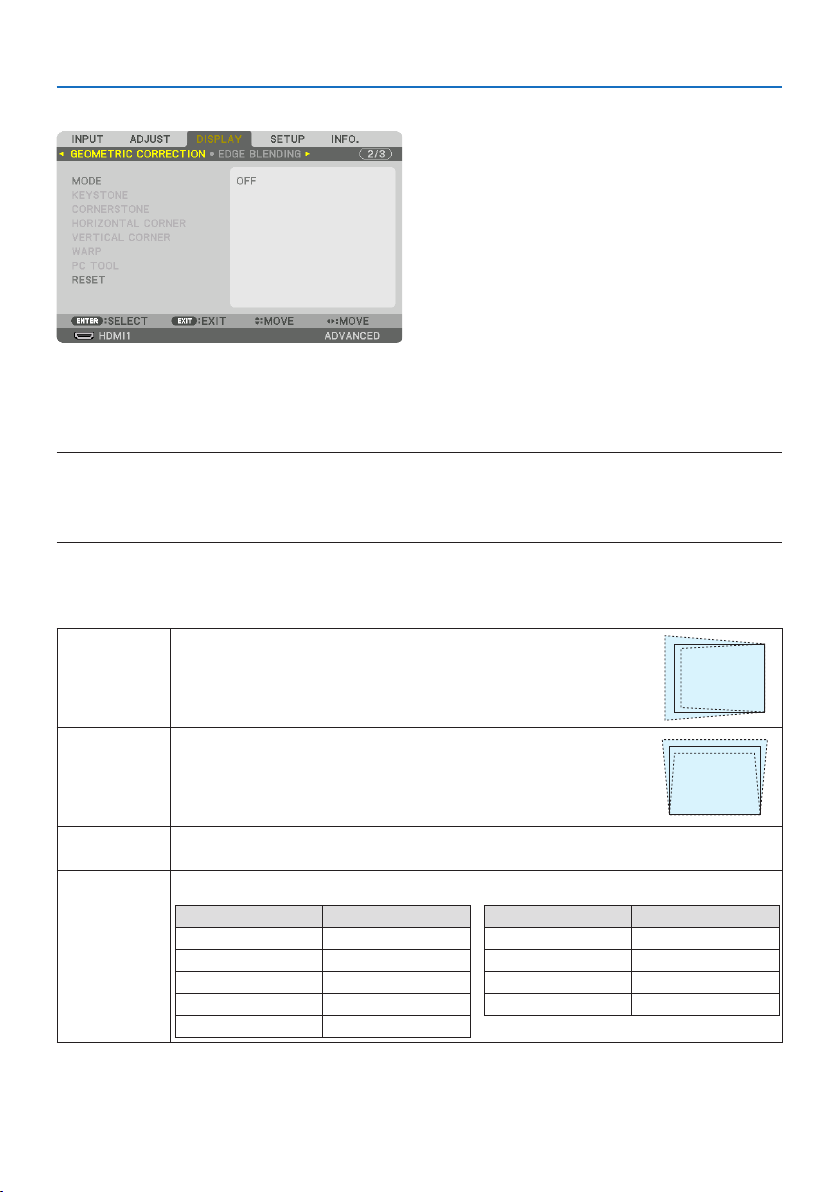
5. Using On-Screen Menu
113
[GEOMETRIC CORRECTION]
MODE
Set pattern for correcting distortion. If [OFF] is selected, the [GEOMETRIC CORRECTION] becomes
ineffective.
NOTE:
•Ifyouneedtochangethe[MENUANGLE],makesuretochangeitbeforeperformingthe[GEOMETRICCORRECTION].If[MENU
ANGLE]ischangedafterperformingthe[GEOMETRICCORRECTION],correctedvalueswillberesettothedefaultvalues.
•Thiscanbesetwhen[3DSETTINGS] →[FORMAT]issetto[OFF(2D)].
KEYSTONE
Correct distortion in horizontal and vertical directions.
HORIZONTALAdjustmentswhenprojectingfromadiagonaldirectiontothescreen.
VERTICALAdjustmentswhenprojectingfromthetoporbottomdirectiontothescreen.
TILTAdjuststhedistortionwhenperformingtrapezoidalcorrectionwiththescreenmovedintheverticaldirection
usingthelensshift.
THROWRATIOAdjustsaccordingtotheprojectionratiooftheoptionallensused.
ModelnameoflensunitAdjustmentrange
NP11FL8
NP12ZL12–15
NP13ZL15–30
NP14ZL29–47
NP15ZL46–71
ModelnameoflensunitAdjustmentrange
NP40ZL8–11
NP41ZL13–30
NP43ZL30–60
NP44ML3
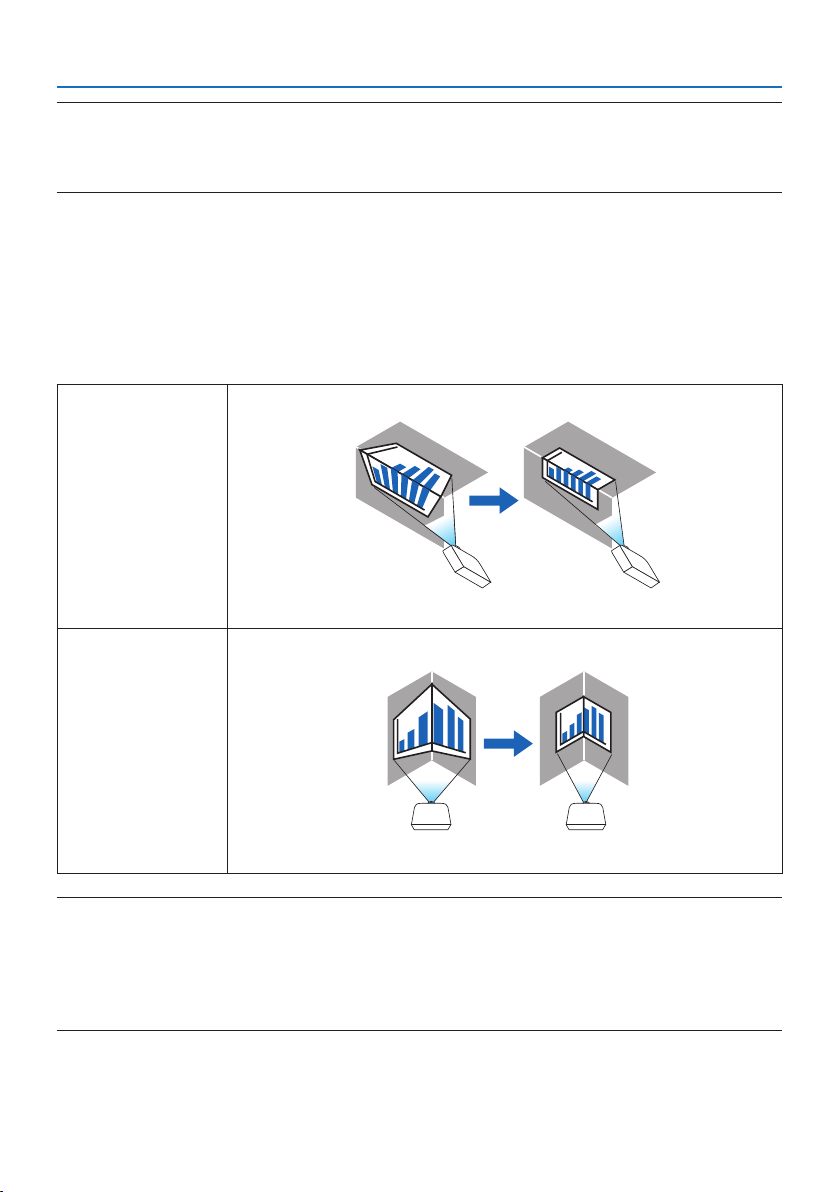
5. Using On-Screen Menu
114
NOTE:
•Whenpowerissuppliedtothedevice,theadjustmentvalueofthe[KEYSTONE]usedpreviouslyisretainedevenifthegradientof
thedeviceischanged.
•Aselectricalcorrectioniscarriedoutby[KEYSTONE],thebrightnessmaybereducedorthescreenqualitymaydeterioratesometimes.
CORNERSTONE
Display the 4-point correction screen and adjust the trapezoidal distortion of the projection screen.
Please refer to “Correcting Horizontal and Vertical Keystone Distortion [CORNERSTONE]” (→ page
45) for details on the operation.
HORIZONTAL CORNER/VERTICAL CORNER
Distortion correction for corner projection such as wall surfaces.
HORIZONTALCORNERPerformscorrectionforprojectionontoawalllyingatanangletothehorizontaldirection.
*Reverseanglecorrectionisalsopossible.
VERTICALCORNERPerformscorrectionforprojectionontoawalllyingatanangletotheverticaldirection.
*Reverseanglecorrectionisalsopossible.
NOTE:
•Whenthemaximumadjustmentrangeisexceeded,distortionadjustmentisdisabled.Setuptheprojectoratanoptimalangleas
thedeteriorationintheimagequalityincreasesasthedistortionadjustmentvolumegetslarger.
•Pleasenotethattheimagewillgooutoffocusduetothedierenceinthedistancebetweentheupperandlowerorleftandright
sidesandthecenterofthescreenforprojectionscuttingacrosscorners.Lenseswithshortfocalpointsarealsonotrecommended
forprojectionscuttingacrosscornersastheimagewillgooutoffocus.
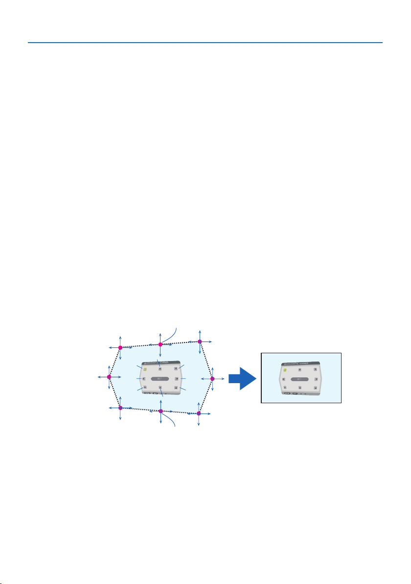
5. Using On-Screen Menu
115
Adjustment method
1.Alignthecursorwiththe[HORIZONTAL CORNER]or[VERTICAL CORNER]ofthe[GEOMETRIC
CORRECTION] menu and then press the ENTER button.
•Theadjustmentscreenwillbedisplayed.
2. Press the ▼▲◀▶ buttons to align the cursor (yellow box) with the target adjustment point
and then press the ENTER button.
•Thecursorwillchangeintoanadjustmentpoint(yellowincolor).
3. Press the ▼▲◀▶ buttons to adjust the corners or sides of the screen and then press the
ENTER button.
•Theadjustmentpointwillgobacktobeingacursor(yellowbox).
Explanation of screen transition
•Theadjustmentpointsofthefourcorners(a,c,fandhinthedrawing)willmoveindepen-
dently.
•Thefollowingadjustmentpointsdieratthe[HORIZONTAL CORNER] and [VERTICAL COR-
NER].
HORIZONTAL CORNER:WhenPointbinthedrawingismoved,andtheuppersideandPoint
g are moved, the lower side will move in a parallel manner.
VERTICAL CORNER:WhenPointdinthedrawingismoved,andtheleftsideandPointeare
moved, the right side will move in a parallel manner.
[Adjustment points of the [HORIZONTAL CORNER] screen and movement points of the
projection screen]
a
b
b
c
d
e
f
g
h
a
c
d
e
f
g
h
Point b will be displaced in a parallel manner at the same time as Points a, b, c
Point g will be displaced in a parallel manner at the same time as Points f, g, h
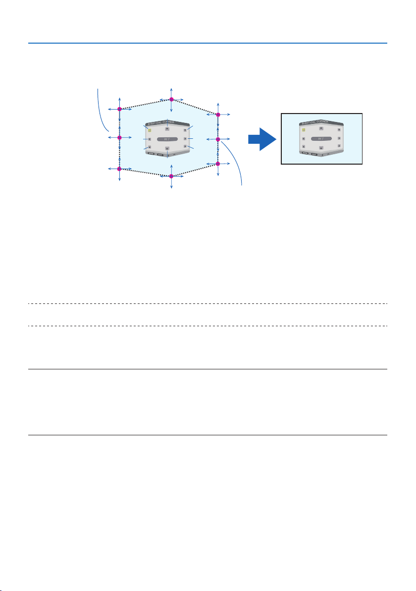
5. Using On-Screen Menu
116
[Adjustment points of the [VERTICAL CORNER] screen and movement points of the projec-
tion screen]
a
a
b
b
c
c
d
d
e
e
f
f
g
g
h
h
Point d will be displaced in a parallel manner at the same time as Points a, d, f
Point e will be displaced in a parallel manner at the same time as Points f, g, h
4. Start from Step 2 onwards to adjust the other points.
5. When the adjustment is completed, press the ▼▲◀▶ buttons to align the cursor with the
[EXIT] in the adjustment screen and then press the ENTER button.
•Switchtothe[GEOMETRIC CORRECTION] menu screen.
6. Press ◀ or ▶buttontomovethecursoronto[OK]thenpress[ENTER].
•Theadjustedvaluesfor[HORIZONTAL CORNER] or [VERTICAL CORNER] are stored and the
screen display goes back to the [GEOMETRIC CORRECTION].
TIP:
•AcommerciallyavailableUSBmouseisavailabletoperformcorrection.(→ page 49)
WARP
Correct projected image distortion on a specific surface as a column or a sphere.
NOTE:
•Whenthemaximumadjustmentrangeisexceeded,distortionadjustmentisdisabled.Setuptheprojectoratanoptimalangle
sincethemoretheadjustmentvolumegetslarge,themoreimagequalitygetsdeterioration.
•Pleasenotethattheimagewillgooutoffocusduetothedierenceinthedistancebetweenperipheriesandthecenterofthe
screenforprojectionscuttingacrosscornersasonacolumnorasphere.Lenseswithshortfocalpointsarealsonotrecommended
forprojectionscuttingacrosscornersastheimagewillgooutoffocus.
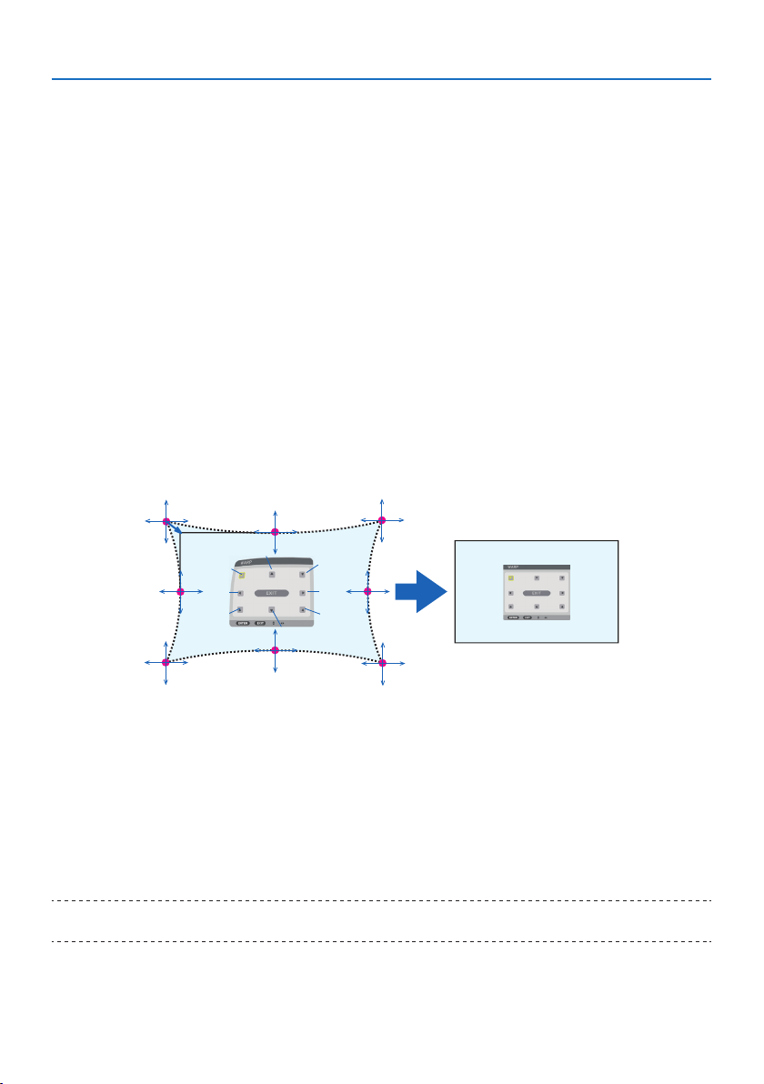
5. Using On-Screen Menu
117
Adjustment method
1. Alignthecursorwiththe[WARP]ofthe[GEOMETRIC CORRECTION] menu and the press
the ENTER.
•Adjustmentscreenwillbedisplayedon.
2. Press the ▼▲◀▶ buttons to align the cursor (blue box) with the target adjustment point
and then press the ENTER.
•Thecursorwillchangeintoanadjustmentpoint(yellowincolor).
3. Press the ▼▲◀▶ buttons to adjust the corners or sides of the screen and then press the
ENTER.
•Thecursorwillbacktoyellowbox.
Explanation for correcting distortion
•Eightadjustmentpointscanbemovedindependently.
•Forleftandrightsides,use◀/▶ buttons for adjusting the range of distortion, and ▼/▲
buttons for adjusting the distortion peak.
•Fortopandbottomsides,use▼/▲ buttons for adjusting the range of distortion, and ◀/▶
buttons for adjusting the distortion peak.
•Forcorners,use▼▲◀▶ buttons for moving positions.
a
b
c
e
h
d
g
f
b
a
c
d
e
f
g
h
4. For adjusting other points, repeat Step2 onwards.
5. Whentheadjustmentiscompleted,movethecursorontothe[EXIT] on the adjustment
screen and press the ENTER.
•Thescreenwillbeswitchedtothe[GEOMETRIC CORRECTION] menu.
The adjustment completion screen will be displayed on.
6. Press ◀ or ▶buttontomovethecursoronto[OK]thenpress[ENTER].
•Theadjustedvaluesfor[WARP] are stored and the screen display goes back to the [GEO-
METRIC CORRECTION].
TIP:
•AcommerciallyavailableUSBmouseisavailabletoperformcorrection.(→ page 49)

5. Using On-Screen Menu
118
PC TOOL
Recall the geometric correction data that is registered in the projector beforehand.
Three types of correction data can be registered.
NOTE:
•Aselectricalcorrectioniscarriedoutingeometriccorrection,thebrightnessmaybeaectedandthepicturequalitymaybe
degraded.
RESET
Reset the adjustment value that has been set up as [MODE] in [GEOMETRIC CORRECTION] (return
to the initial value).
•Thisisineectivewhen[MODE] is set [OFF].
•ResetcanbeexecutedbypressingandholdingtheGeometric. button on the remote control for
over 2 seconds.
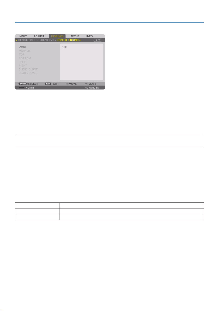
5. Using On-Screen Menu
119
[EDGE BLENDING]
This adjusts the edges (boundaries) of the projection screen when projecting high resolution videos
using a combination of several projectors in the up, down, left and right positions.
MODE
This enables or disables the [EDGE BLENDING] function.
When [MODE] is set to [ON], the [MARKER], [TOP], [BOTTOM], [LEFT], [RIGHT], [BLACK LEVEL], and
[BLEND CURVE] settings can be adjusted.
NOTE:
•Thiscanbesetwhen[3DSETTINGS] →[FORMAT]issetto[OFF(2D)].
MARKER
Set whether to display marker or not when adjusting the range and display position. When turned
on, magenta and red markers for adjusting the range adjustment and cyan and green markers for
adjusting the display position will be displayed.
TOP/BOTTOM/LEFT/RIGHT
This selects the [EDGE BLENDING] locations on the left, right, top and bottom on the screen.
The following settings can be adjusted when an item is selected. (→ page 75)
CONTROL Enable[TOP],[BOTTOM],[LEFT],and[RIGHT]functions.
RANGEAdjusttherange(width)oftheedgeblending.
POSITIONAdjustthedisplaypositionoftheedgeblending.
BLEND CURVE
Set brightness for the [EDGE BLENDING] sections. (→ page
78)
BLACK LEVEL
Adjust the black level of the [EDGE BLENDING] section. (→ page
79)
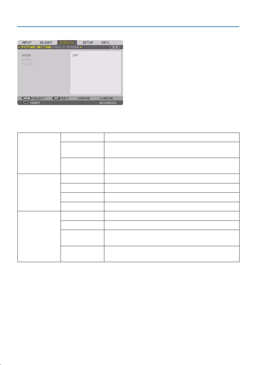
5. Using On-Screen Menu
120
[PICTURE SETTING]
This sets the division conditions for reducing or enlarging the image area and displaying it in the
desired position or for projecting using a combination of several projectors.
Please refer to “4. Multi-Screen Projection” (→ page 66) for details.
MODE OFFUsetheprojectorinastandalonestate.
ZOOM Thisadjuststhepositionandwidthofthevideoareathatyouwishtodivide.
Theedgeblendingwidthwillalsobeautomaticallysettothatwidth.
TILINGThisassignsthedividedscreenstotheprojectors.Theedgeblendingfunction
willalsobesetautomatically.
ZOOM HORIZONTALZOOMThisenlargesthevideoareainthehorizontaldirection.
VERTICALZOOMThisenlargesthevideoareaintheverticaldirection.
HORIZONTALPOSITIONThisshiftsthevideoareainthehorizontaldirection.
VERTICALPOSITIONThisshiftsthevideoareaintheverticaldirection.
TILINGWIDTHThisselectsthenumberofprojectorstobearrangedhorizontally.
HEIGHTThisselectsthenumberofprojectorstobearrangedvertically.
HORIZONTALPOSITIONThisselectsthepositionoftheprojectorstartingfromtheleftamongthose
arrangedhorizontally.
VERTICALPOSITIONThisselectsthepositionoftheprojectorstartingfromthetopamongthose
arrangedvertically.
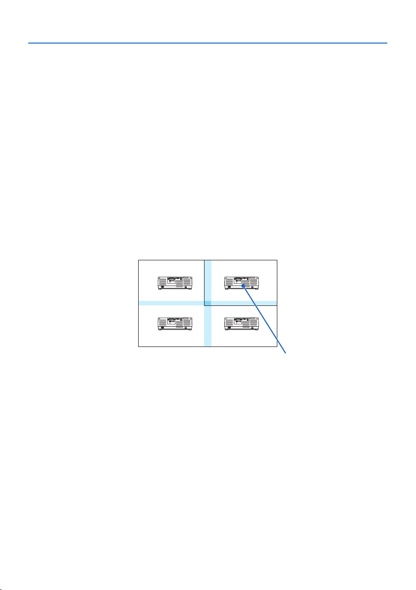
5. Using On-Screen Menu
121
Conditions for using tiling
•Alltheprojectorsneedtofullthefollowingconditions.
- The panel size must be the same
- The projection screen size must be the same
- The left and right ends or top and bottom ends of the projection screen must be consistent.
- The settings for the [LEFT] and [RIGHT] of the [EDGE BLENDING] are the same
- The settings for the [TOP] and [BOTTOM] of the [EDGE BLENDING] are the same
If the tiling conditions are satisfied, the video screen of the projector at each installation position
will be automatically extracted and projected.
If the tiling conditions are not satisfied, adjust the video screen of the projector at each installa-
tion position using the zoom function.
•AssignauniquecontrolIDtoeachprojector.
•Setthe“Colorsetting”and“DeepColorsetting”onyourBlu-rayplayerorcomputerto“Auto”.Refer
to the owner’s manual accompanied with your Blu-ray player or computer for more information.
Connect an HDMI output signal of your Blu-ray player or computer to the first projector and then
connect to the HDBaseT OUT/Ethernet port on the first projector to the HDBaseT IN/Ethernet port
on the second projector, same to the sequel projectors..
Tiling setting example) Number of horizontal units = 2, Number of vertical units = 2
Horizontal order = Second unit
Vertical order = First unit
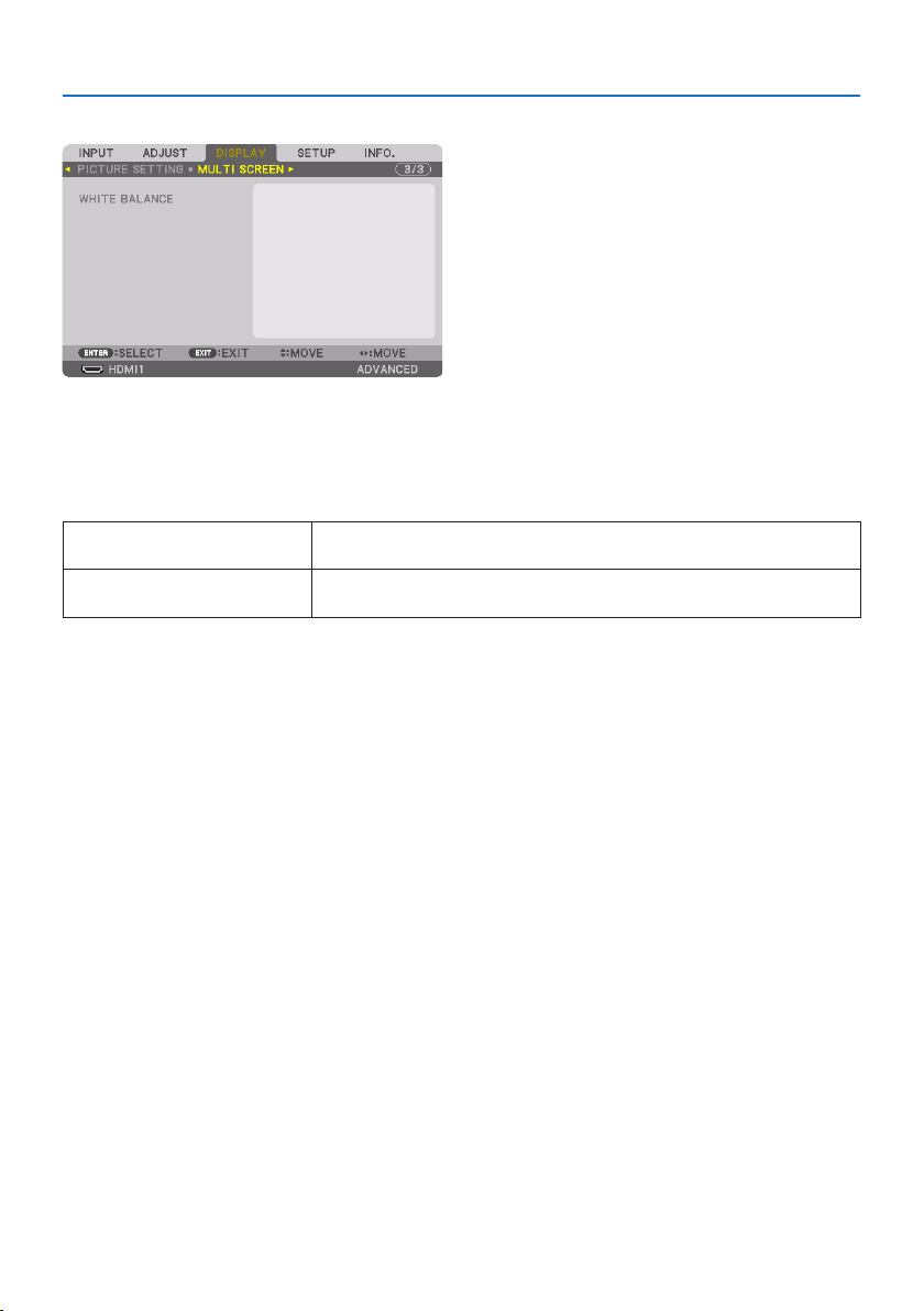
5. Using On-Screen Menu
122
[MULTI SCREEN]
WHITE BALANCE
This adjusts the white balance for each projector when projecting using a combination of several
projectors.
This can be adjusted when [MODE] is set to [ON].
CONTRASTW,CONTRASTR,CONTRAST
G,CONTRASTB
Adjustingthewhitecolorofthevideo.
BRIGHTNESSW,BRIGHTNESSR,
BRIGHTNESSG,BRIGHTNESSB
Adjustingtheblackcolorofthevideo.
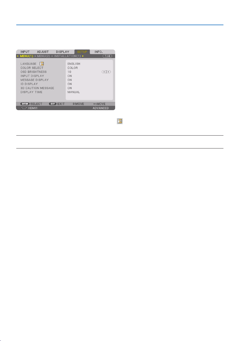
5. Using On-Screen Menu
123
5-7. Menu Descriptions & Functions [SETUP]
[MENU(1)]
SelectingMenuLanguage[LANGUAGE]
You can choose one of 30 languages for on-screen instructions.
NOTE:
•Yoursettingwillnotbeaectedevenwhen[RESET]isdonefromthemenu.
SelectingMenuColor[COLOR SELECT]
Youcanchoosebetweentwooptionsformenucolor:[COLOR] and [MONOCHROME].
SelectingMenuBrightness[OSD BRIGHTNESS]
Select the brightness of the On-Screen display (menu, source display and messages) from 10 levels.
TurningOn/OSourceDisplay[INPUT DISPLAY]
This option turns on or off input name display such as [HDMI1], [HDMI2], [DisplayPort], [COMPUTER],
[HDBaseT] to be displayed on the top right of the screen.
Turningmessagesonando[MESSAGE DISPLAY]
This option selects whether or not to display projector messages at the bottom of the projected
image.
Even when [OFF] is selected, the security lock warning is displayed. The security lock warning turns
off when the security lock is canceled.
TurningOn/OControlID[ID DISPLAY]
This option turns on or off the ID number which is displayed when the ID SET button on the remote
control is pressed. (→ page
139)
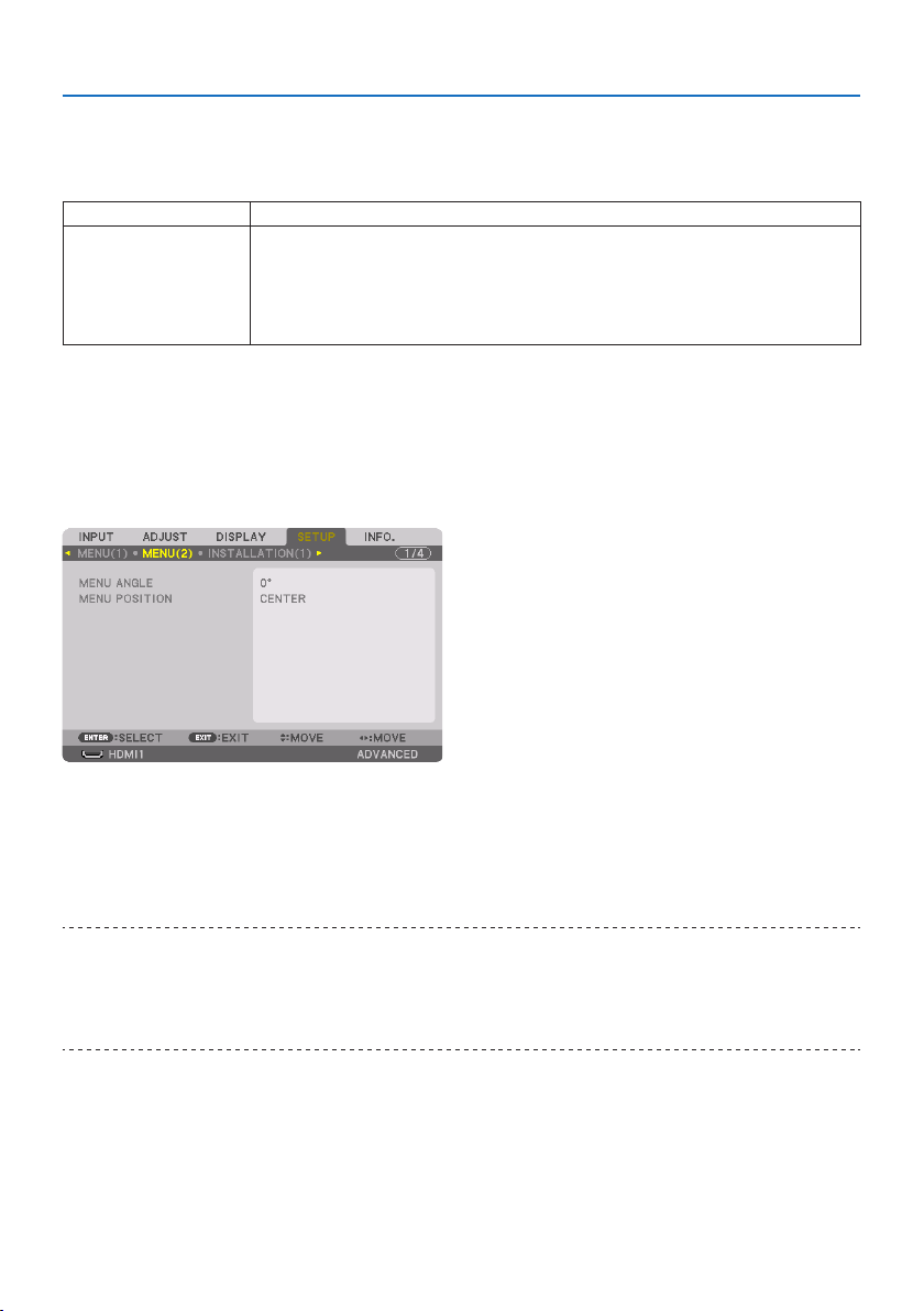
5. Using On-Screen Menu
124
[3D CAUTION MESSAGE]
This selects whether to display a caution message or not when switching to a 3D video.
The default condition when shipped from the factory is [ON].
OFFThe3Dcautionmessagescreenwillnotbedisplayed.
ON The3Dcautionmessagescreenwillbedisplayedwhenswitchingtoa3Dvideo.PresstheENTER
buttontocancelthemessage.
•Themessagewilldisappearautomaticallyafter60secondsorwhenotherbuttonsarepressed.If
itdisappearsautomatically,the3Dcautionmessagewillbedisplayedagainwhenswitchingtoa
3Dvideo.
SelectingMenuDisplayTime[DISPLAY TIME]
This option allows you to select how long the projector waits after the last touch of a button to turn
off the menu. The preset choices are [MANUAL], [AUTO 5 SEC], [AUTO 15 SEC], and [AUTO 45 SEC].
The [AUTO 45 SEC] is the factory preset.
[MENU(2)]
[MENU ANGLE]
Select the direction for displaying the menu.
[MENU POSITION]
Shift the menu displaying position. You can choose from 9 locations.
TIP:
•Thedisplaypositionofthemenuissavedevenwhenthepowersupplyoftheprojectoristurnedo.
•Whenyouchangethe[MENUANGLE],thedisplaypositionofthemenureturnstotheoriginalstatewhenitwasrstshippedfrom
thefactory.
•Inputterminalandmessagedisplayingpositionarenotinuencedbythe[MENUPOSITION].
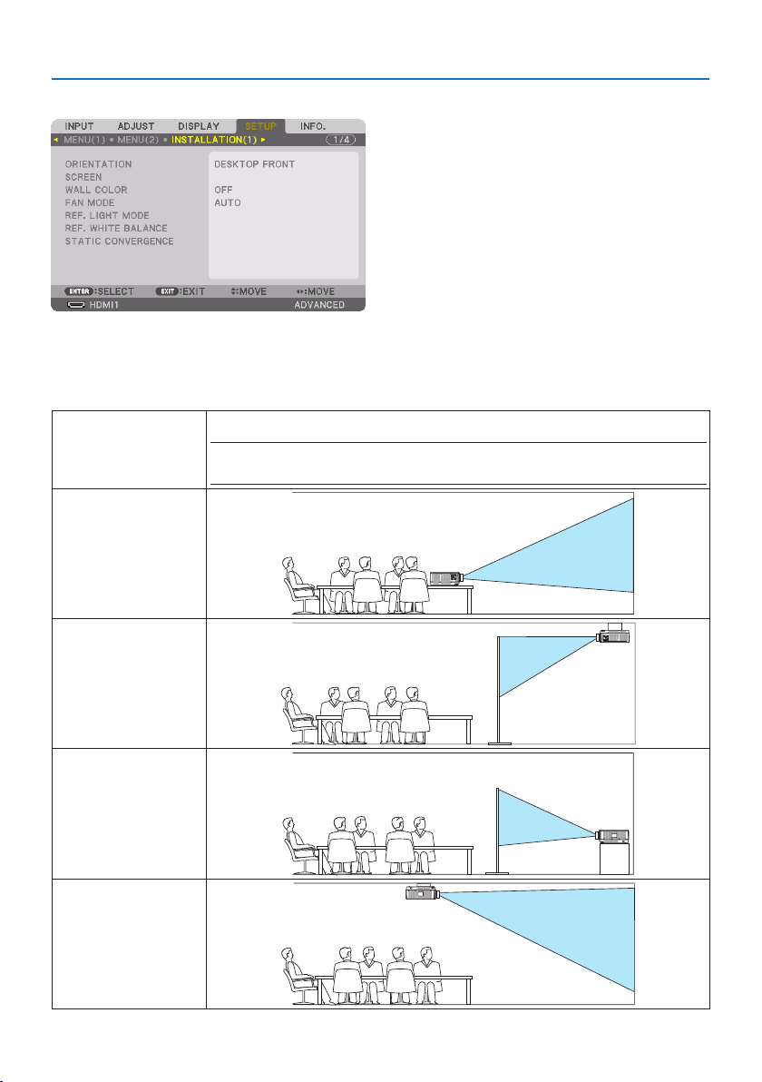
5. Using On-Screen Menu
125
[INSTALLATION(1)]
SelectingProjectorOrientation[ORIENTATION]
Thisreorientsyourimageforyourtypeofprojection.Theoptionsare:desktopfrontprojection,
ceiling rear projection, desktop rear projection, and ceiling front projection.
AUTOThisautomaticallydetectsandprojectsthe[DESKTOPFRONT]and[CEILINGFRONT].
NOTE:
•The[DESKTOPREAR]and[CEILINGREAR]willnotbedetected.Pleaseselectmanually.
DESKTOPFRONT
CEILINGREAR
DESKTOPREAR
CEILINGFRONT
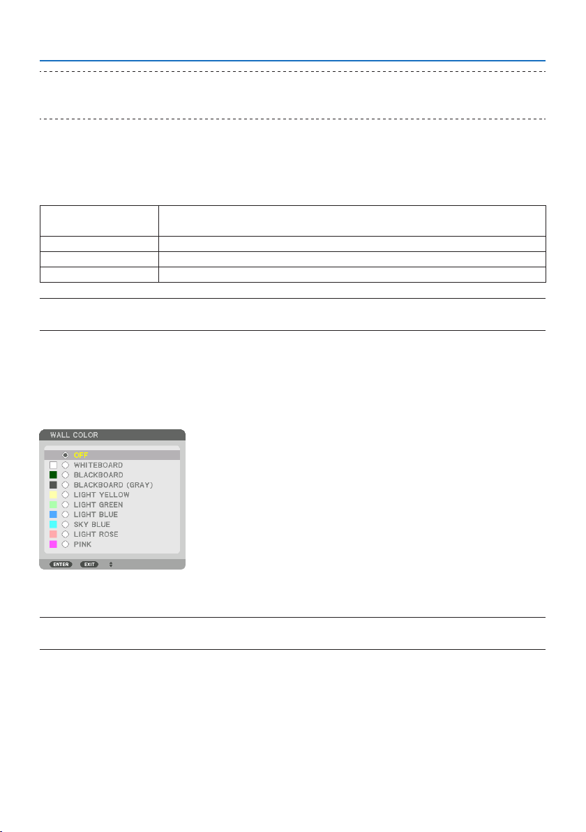
5. Using On-Screen Menu
126
TIP:
•Checkwhethertheautomatic[DESKTOPFRONT]isinstalledwithin±10degreesforoorinstallationandwhetherthe[CEILING
FRONT]iswithin±10degreesforceilinginstallation.Selectmanuallywhentheprojectionscreenisinverted.
Selecting Aspect Ratio and Position for Screen [SCREEN]
[SCREEN TYPE]
Sets the aspect ratio of the projection screen.
FREETheratiooftheliquidcrystalpanelisselected.Selectthiswhenprojectingmulti-screenand17:9
screen(2K).
4:3SCREENForascreenwitha4:3aspectratio
16:9SCREENForascreenwitha16:9aspectratio
16:10SCREENForascreenwitha16:10aspectratio
NOTE:
•Afterchangingthescreentype,checkthesettingof[ASPECTRATIO]inthemenu.(→ page 104)
[POSITION]
Adjust the screen position. Depending on the model you use and the screen type, the function may
become ineffective and the adjustable range may vary.
UsingtheWallColorCorrection[WALL COLOR]
This function allows for quick adaptive color correction in applications where the screen material
is not white.
NOTE:
•Selecting[WHITEBOARD]reduceslightsourcebrightness.
SelectingFanMode[FAN MODE]
Fan Mode is used to set the speed of the internal cooling fan.

5. Using On-Screen Menu
127
MODE Selectoneamongfourmodes:[AUTO],[NORMAL],[HIGH],and[HIGHALTITUDE].
AUTOThebuilt-infansautomaticallyrunatvariablespeedaccordingtothedetected
temperatureandatmosphericpressurebythebuilt-insensor.
NORMALThebuilt-infansrunattheappropriatespeedbasedonthedetectionbythe
built-intemperaturesensor.
HIGHThebuilt-infansrunathighspeed
HIGHALTITUDEThebuilt-infansrunathighspeed.Selectthisoptionwhenusingtheprojector
ataltitudesapproximately5500feet/1700metersorhigher.
NOTE:
•Makesurethespeedissetto[HIGH]whenyouareusingthisdevicecontinuouslyforseveraldays.
•Set[FANMODE]to[AUTO]or[HIGHALTITUDE]whenusingtheprojectorataltitudesapproximately5500feet/1700metersor
higher.
•Usingtheprojectorataltitudesapproximately5500feet/1700metersorhigherwithoutsettingto[AUTO]or[HIGHALTITUDE] can
causetheprojectortooverheatandtheprotectorcouldshutdown.Ifthishappens,waitacoupleminutesandturnontheprojector.
•Usingtheprojectorataltitudeslessthanapproximately5500feet/1700metersandsettingto[HIGHALTITUDE] can cause the
projectortoovercool,causingtheimagetoicker.Switch[FANMODE]to[AUTO].
• Usingtheprojectorataltitudesapproximately5500feet/1700metersorhighercanshortenthelifeofopticalcomponentssuch
asthelightsource.
•Yoursettingwillnotbeaectedevenwhen[RESET]isdonefromthemenu.
TIP:
•When[HIGHALTITUDE]isselectedfor[FANMODE],asymboliconwillbedisplayedatthebottomofthemenu.
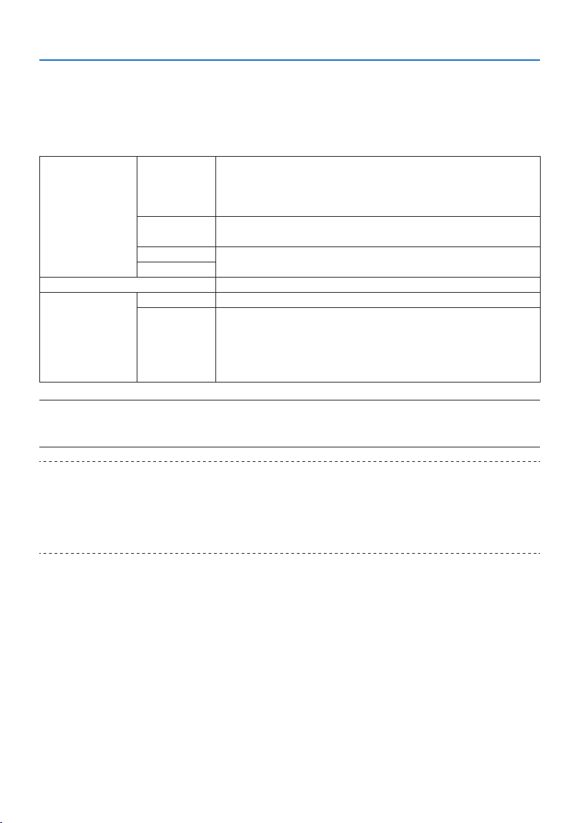
5. Using On-Screen Menu
128
[REF. LIGHT MODE]
Set this when you want to change the brightness of the projector or when you want to use the
projector in the energy-saving mode (→ page
41).
This can also be used to adjust the brightness between the different projectors when using a com-
bination of multiple projectors.
REF.LIGHTMODEBOOSTThepicturebecomesbrighterthanthe[NORMAL]mode.However,theoperating
noiseandpowerconsumptionwillalsoincreaseduetocontrolofthecoolingfanac-
cordingtothebrightness.Thelifeoftheopticalcomponentsmayalsobeshortened
dependingontheoperatingenvironment.
NORMALThelightmoduleluminance(brightness)willbecome100%andthescreenwill
turnbright.
ECO1 Bycontrollingthebrightnessandfanspeedaccordingtotheselectedsetting,
energycanbesavedandmotionnoiseandthepowerconsumptioncanbelowered.
ECO2
REF.LIGHTADJUSTBrightnesscanbeadjustedin1%incrementsfrom50to100%.
CONSTANTBRIGHTNESSOFF[CONSTANTBRIGHTNESS]modewillbecanceled.
ON Maintainsthebrightnessthatisineectatthetime[ON]isselected.Unless[OFF] is
selected,thesamesettingswillremainineectevenwhentheprojectoristurned
o.
•Tore-adjustthebrightness,rstturnthissetting[OFF]beforemakingfurther
adjustments.
NOTE:
•When[WALLCOLOR]issetto[WHITEBOARD],[REF.LIGHTMODE]cannotbeselected.
•If[CONSTANTBRIGHTNESS]issetto[ON],then[REF.LIGHTMODE]and[REF.LIGHTADJUST]cannotbeselected.
TIP:
•Brightnessnormallydecreaseswithuse,butbyselecting[CONSTANTBRIGHTNESS]mode,sensorsinsidetheprojectordetect
brightnessandautomaticallyadjusttheoutput,therebymaintainingaconstantbrightnessthroughoutthelifeofthelightmodule.
However,ifoutputisalreadyatitsmaximum,brightnesswilldecreasewithuse.
Forthisreason,whenusingmulti-screenprojection,itisrecommendedtoadjustthebrightnesstoaslightlylowerlevel,then
settingthe[CONSTANTBRIGHTNESS]modeto[ON].

5. Using On-Screen Menu
129
[REF. WHITE BALANCE]
This feature allows you to adjust the white balance for all signals.
The white and black levels of the signal are adjusted for optimum color reproduction.
Uniformity is also adjusted when the redness (R) and blueness (B) of the white color in the screen’s
horizontal (left/right) direction are uneven.
CONTRASTR,CONTRASTG,
CONTRASTB
Theseadjustthepicture’swhitecolor.
BRIGHTNESSR,BRIGHTNESS
G,BRIGHTNESSB
Theseadjustthepicture’sblackcolor.
UNIFORMITYRThefurtherthisissettothe+side,thestrongertherednessontheleftsideofthepicture(increas-
ingtowardstheleftedge)andtheweakertherednessontherightsideofthepicture(decreasing
towardstherightedge).
Thisisreversedwhensettothe–side.
UNIFORMITYBThefurtherthisissettothe+side,thestrongerthebluenessontheleftsideofthepicture
(increasingtowardstheleftedge)andtheweakerthebluenessontherightsideofthepicture
(decreasingtowardstherightedge).
Thisisreversedwhensettothe–side.
[STATIC CONVERGENCE]
This features allows you to adjust for color deviation in the picture.
This can be adjusted in units of ± 1 pixel in the horizontal direction for [HORIZONTAL R], [HORIZONTAL
G], and [HORIZONTAL B], in the vertical direction for [VERTICAL R], [VERTICAL G], and [VERTICAL B].
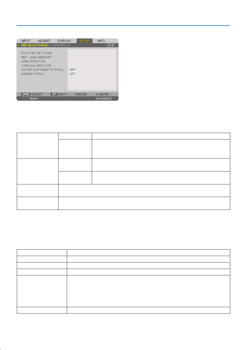
5. Using On-Screen Menu
130
[INSTALLATION(2)]
[SHUTTER SETTINGS]
Enabling and disabling the lens shutter function. You can also set how long the light will take to
fade in and fade out when either the SHUTTER button on the remote control.
POWERONSHUTTEROPENWhenthepoweristurnedon,thelightsourcecomesonandthepictureisprojected.
CLOSEThelightsourcedoesnotcomeonwhenthepoweristurnedon.
WhentheSHUTTERbuttonispressed,theshutterisreleasedandthelightsourceis
turnedon.
PICTUREMUTESHUTTEROPENThelightsourceisstillonwhenthepictureisturnedoforswitchingtheinput
terminals.
CLOSEThelightsourceturnsowhenthepictureisturnedoforswitchingtheinput
terminals.
FADEINTIMESethowlongthelightwilltaketofadeinaftertheSHUTTERbuttonispressed.
Thetimecanbesetfrom0to10secondsinincrementsof1second.
FADEOUTTIMESethowlongthelightwilltaketofadeoutaftertheSHUTTERbuttonispressed.
Thetimecanbesetfrom0to10secondsinincrementsof1second.
UsingtheReferenceLensMemoryFunction[REF. LENS MEMORY]
This function serves to store the adjusted values common to all input sources when using the [LENS
SHIFT], motorized [ZOOM], and motorized [FOCUS] functions of the projector or the remote control.
The adjusted values stored in memory can be used as a reference to the current.
PROFILESelectastored[PROFILE]number.
STOREStoresthecurrentadjustedvaluesinmemoryasareference.
MOVE Appliestheadjustedreferencevaluesstoredin[STORE]tothecurrentsignal.
RESETResetselected[PROFILE]number[REF.LENSMEMORY]tothefactorydefaultsettings.
LOADBYSIGNALWhenyouswitchsignalsthelenswillshifttothelensshift,zoom,andfocusvaluesfortheselected
[PROFILE]number.
Ifnoadjustedvalueshavebeensavedto[LENSMEMORY],thelenswillapply[REF.LENSMEMORY]
adjustedvalues.Alternatively,ifnoadjustedvalueshavebeensavedto[REF.LENSMEMORY],the
unitwillreturntofactorydefaultsettings.
FORCEDMUTEToturnotheimageduringlensshift,select[YES].
•ThisfunctionisnotavailableforthelensunitNP44ML.

5. Using On-Screen Menu
131
TIP:
•Adjustedvaluesin[REF.LENSMEMORY]willnotbereturnedtodefaultwhenperforming[CURRENTSIGNAL]or[ALLDATA] for
[RESET]fromthemenu.
•Tostoreadjustedvaluesforeachinputsource,usetheLensMemoryfunction.(→ page 59,108)
[LENS POSITION]
Set back the lens to the home position.
[LENS CALIBRATION]
The adjustment range of the zoom, focus, and shift of the mounted lens is calibrated.
Be sure to carry out [LENS CALIBRATION] after replacing the lens.
•ThisfunctionisnotavailableforthelensunitNP44ML.
[COLOR UNIFORMITY(TOOL)]
Retrieves the uniformity adjustment value registered in the projector after adjusting with the
ProAssist software application.
[GAMMA(TOOL)]
Retrieves the Gamma Tone adjustment value registered in the projector after adjusting with the
ProAssist software application.
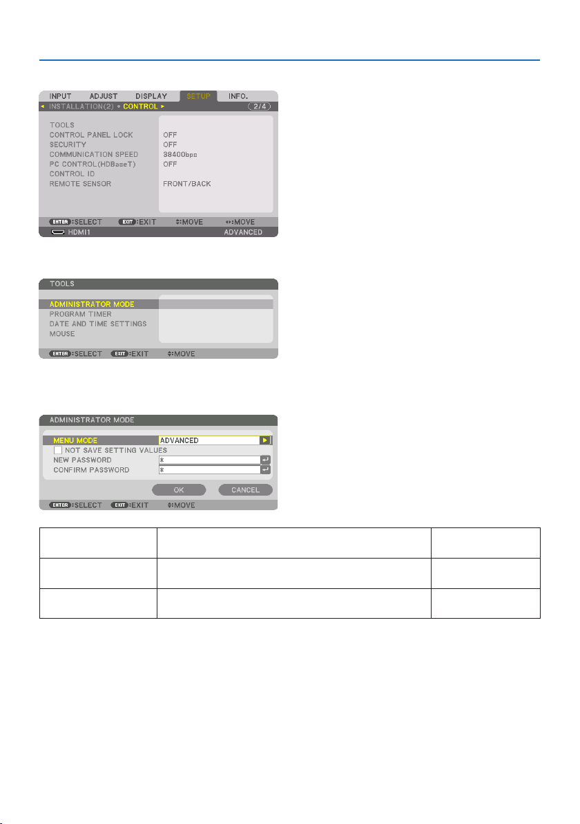
5. Using On-Screen Menu
132
[CONTROL]
TOOLS
ADMINISTRATOR MODE
This allows you to select [MENU MODE], save settings, and set a password for the administrator mode.
MENU MODE Selecteither[BASIC]or[ADVANCED]menu.
(→ page 83)
—
NOTSAVESETTINGVALUESPlacingacheckmarkwillnotsaveyourprojectorsettings.
Clearthischeckboxtosaveyourprojectorsettings.
—
NEWPASSWORD,CONFIRM
PASSWORD
Assignapasswordfortheadministratormode.Up to 10 alphanumeric
characters
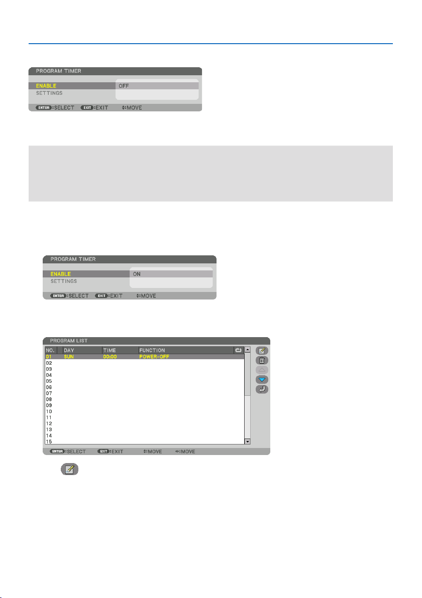
5. Using On-Screen Menu
133
PROGRAM TIMER
This option turns on/standby the projector and changes video signals, and selects [LIGHT MODE]
automatically at a specified time.
Important:
•Beforeusing[PROGRAMTIMER],makesurethatthe[DATEANDTIMESETTINGS]featureisset.(→ page 137)
MakesurethattheprojectorisinthestandbyconditionwiththePOWERcordconnected.
Theprojectorhasabuilt-inclock.Theclockwillkeepworkingforaboutamonthafterthemainpoweristurnedo.Ifthemain
powerisnotsuppliedtotheprojectorforamonthormore,itrequirestoset[DATEANDTIMESETTINGS]featureagain.
Setting a new program timer
1. Onthe[PROGRAM TIMER] screen, use the ▲ or ▼buttontoselect[SETTINGS] and press
the ENTER button.
The [PROGRAM LIST] screen will be displayed.
2. Select a blank program number and press the ENTER button.
The [ (EDIT)] screen will be displayed.
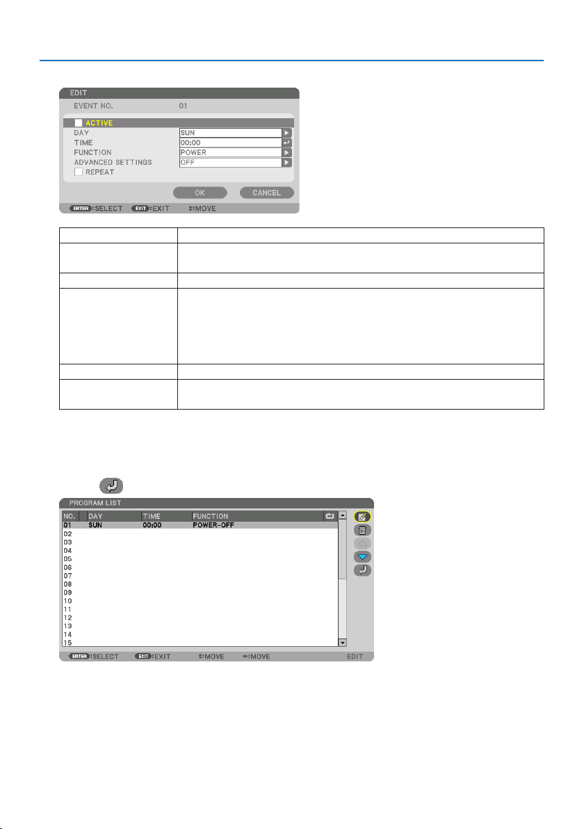
5. Using On-Screen Menu
134
3. Make settings for each item as required.
ACTIVEPlaceacheckmarktoenabletheprogram.
DAYSelectdaysoftheweekfortheprogramtimer.ToexecutetheprogramfromMondaytoFriday,
select[MON-FRI].Toexecutetheprogramineverydaybasis,select[EVERYDAY].
TIMESetthetimetoexecutetheprogram.Entertimein24-hourformat.
FUNCTIONSelectafunctiontobeexecuted.Selecting[POWER]willallowyoutoturnonorothe
projectorbysetting[ADVANCEDSETTINGS].Selecting[INPUT]willallowyoutoselectan
inputterminalbysetting[ADVANCEDSETTINGS].Selecting[LIGHTMODE]willallowyouto
selectoneoptionamong[BOOST],[NORMAL],[ECO1],and[ECO2]for[LIGHTMODE]bysetting
[ADVANCEDSETTINGS].
ADVANCEDSETTINGSSelectoneoptionfortheselecteditemin[FUNCTION].
REPEATPlaceacheckmarktorepeattheprogramcontinuingbasis.Tousetheprogramthisweekonly,
clearthecheckmark.
4. Select[OK] and press the ENTER button.
This will complete the settings.
You will be returned to the [PROGRAM LIST] screen.
5. Select[
(BACK)] and press the ENTER button.
You will be returned to the [PROGRAM TIMER] screen.
6. Select[EXIT] and press the ENTER button.
You will be returned to the [TOOLS] screen.

5. Using On-Screen Menu
135
NOTE:
•Upto30dierenttimersettingscanbeprogrammed.
•TheProgramTimerisexecutedonasettimebasis,notinaprogrambasis.
•Oncetheprogramnotmarkedwithacheckin[REPEAT]hasbeenexecuted,thecheckmarkinthe[ACTIVE]checkboxwillbecleared
automaticallyandtheprogramwillbedisabled.
•Whentheon-timeandtheo-timesetforthesametime,theo-timesettingwilltakepreference.
•Whentwodierentsourcesaresetforthesametime,thelargerprogramnumberwilltakepreference.
•Theon-timesettingwillnotbeexecutedwhilethecoolingfansarerunningoranerrorisoccurring.
•Iftheo-timesettingisexpiredundertheconditioninwhichthepoweroisnotpossible,theo-timersettingwillnotbeexecuted
untilthepowerobecomespossible.
•Programsnotmarkedwithacheckmarkin[ACTIVE]ofthe[EDIT]screenwillnotbeexecutedeveniftheProgramTimerisenabled.
•Whentheprojectoristurnedonbyusingtheprogramtimerandifyouwanttoturnotheprojector,settheo-timeordoit
manuallysoasnottoleavetheprojectoronforalongperiodoftime.
Activating the program timer
1. Select[ENABLE]onthe[PROGRAM TIMER] screen and press the ENTER button.
The selection screen will be displayed.
2. Press the ▼buttontoalignthecursorwith[ON] and then press the ENTER button.
Return to the [PROGRAM TIMER] screen.
NOTE:
•Whentheeectivesettingsofthe[PROGRAMTIMER]havenotbeensetto[ON],theprogramwillnotbeexecutedevenifthe
[ACTIVE]itemsinthe[PROGRAMLIST]havebeenticked.
•Evenwhentheeectivesettingsofthe[PROGRAMTIMER]aresetto[ON],the[PROGRAMTIMER]willnotworkuntilthe[PROGRAM
TIMER]screenisclosed.
Editing the programmed settings
1. Onthe[PROGRAM LIST] screen, select a program you want to edit and press the ENTER
button.
2. Changethesettingsonthe[EDIT] screen.
3. Select[OK] and press the ENTER button.
The programmed settings will be changed.
You will be returned to the [PROGRAM LIST] screen.
Changing the order of programs
1. Onthe[PROGRAM LIST] screen, select a program whose order you want to change and
press the ▶ button.
2. Press the ▼ button to select ▲ or ▼.
3. Press the ENTER button a few times to select a row to which you wish to move the program.
The order of the programs will be changed.

5. Using On-Screen Menu
136
Deleting the programs
1. Onthe[PROGRAM LIST] screen, select a program number you want to delete and press
the ▶ button.
2. Press the ▼buttontoselect[
(DELETE)].
3. Press the ENTER button.
The confirmation screen will be displayed.
4. Select[YES] and press the ENTER button.
The program will be deleted.
This will complete deleting the program.
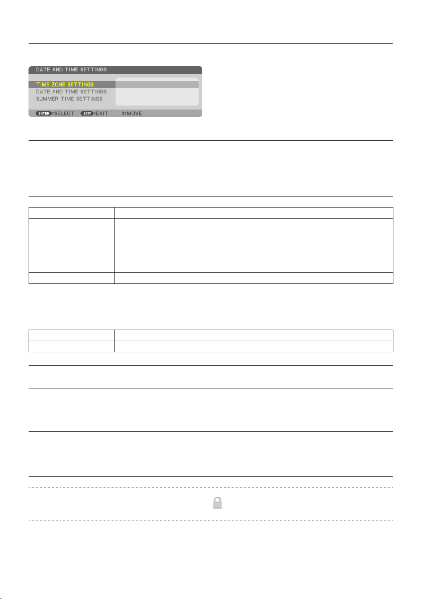
5. Using On-Screen Menu
137
DATE AND TIME SETTINGS
You can set the current time, month, date, and year.
NOTE:
•Theprojectorhasabuilt-inclock.Theclockwillkeepworkingforaboutamonthafterthemainpoweristurnedo.Ifthemain
powerisoforamonthormore,thebuilt-inclockwillcease.Ifthebuilt-inclockceases,setthedateandtimeagain.Thebuilt-in
clockwillnotceasewhileinthestandbymode.Inordertoactivatethebuilt-inclockcontinuouslyevenwhentheprojectorisnot
used,leaveitinthestandbystatenotpluggingothepowercord.
TIMEZONESETTINGSSelectyourtimezone.
DATEANDTIMESETTINGSSetyourcurrentdate(MM/DD/YYYY)andtime(HH:MM).
INTERNETTIMESERVER:Ifyouplaceacheckmark,theprojector’sbuilt-inclockwillbesynchronized
withanInternettimeserverinevery24hoursandatthetimeofprojector’sstartup.
UPDATE:Synchronizestheprojector’sbuilt-inclockimmediately.The[UPDATE]buttonisnotavail-
ableunlessthe[INTERNETTIMESERVER]checkboxisturnedon.
SUMMERTIMESETTINGSIfyouplaceacheckmark,theclockfordaylightsavingwillbeenabled.
[MOUSE]
This function is for using a commercially available USB mouse via the USB-A port on this projector.
BUTTON Selectforusingthemouseeitherbyrightorlefthand.
SENSITIVITYSelectthesensitivityofmouseamong[FAST],[MEDIUM]and[SLOW].
NOTE:
•ThissettingisnotguaranteedmotionofallcommerciallyavailableUSBmouses.
DisablingtheCabinetButtons[CONTROL PANEL LOCK]
This option turns on or off the [CONTROL PANEL LOCK] function.
NOTE:
•Howtocancelthe[CONTROLPANELLOCK]
Whenthe[CONTROLPANELLOCK]issetto[ON],presstheEXITbuttononthecabinetfor10secondsorlongertocancelthe[CONTROL
PANELLOCK]setting.
TIP:
•Whenthe[CONTROLPANELLOCK]isturnedon,akeylockicon[
]willbedisplayedatthebottomrightofthemenu.
•This[CONTROLPANELLOCK]doesnotaecttheremotecontrolfunctions.

5. Using On-Screen Menu
138
EnablingSecurity[SECURITY]
This feature turns on or off the [SECURITY] function.
Unless the correct keyword is entered, the projector cannot project an image. (→ page
50)
NOTE:
•Yoursettingwillnotbeaectedevenwhen[RESET]isdonefromthemenu.
SelectingCommunicationSpeed[COMMUNICATION SPEED]
This feature sets the communication speed for the PC Control port (D-Sub 9P). Make sure to set the
appropriate speed for the device to connect.
NOTE:
•Yourselectedcommunicationspeedwillnotbeaectedevenwhen[RESET]isdonefromthemenu.
[PC CONTROL(HDBaseT)]
Set this to [ON] when controlling the projector from a computer using RS-232C via an HDBaseT-
compatible transmitter (sold separately).
SettingIDtotheProjector[CONTROL ID]
You can operate multiple projectors separately and independently with the single remote control
that has the [CONTROL ID] function. If you assign the same ID to all the projectors, you can conve-
niently operate all the projectors together using the single remote control. To do so, you have to
assign an ID number to each projector.
CONTROLIDNUMBERSelectanumberfrom1to254youwishtoassigntoyourprojector.
CONTROLIDSelect[OFF]toturnothe[CONTROLID]settingandselect[ON]toturnonthe[CONTROLID]
setting.
NOTE:
•When[ON]isselectedfor[CONTROLID],theprojectorcannotbeoperatedbyusingtheremotecontrolthatdoesnotsupportthe
[CONTROLID]function.(Inthiscasethebuttonsontheprojectorcabinetcanbeused.)
•Yoursettingwillnotbeaectedevenwhen[RESET]isdonefromthemenu.
•PressingandholdingtheENTERbuttonontheprojectorcabinetfor10secondswilldisplaythemenuforcancelingtheControlID.
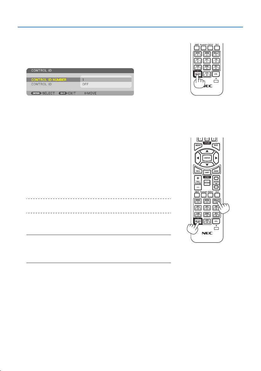
5. Using On-Screen Menu
139
Assigning or Changing the Control ID
1. Turn on the projector.
2. Press the ID SET button on the remote control.
The [CONTROL ID] screen will be displayed.
If the projector can be operated with the current remote control
ID, the [ACTIVE] will be displayed. If the projector cannot be oper-
ated with the current remote control ID, the [INACTIVE] will be
displayed. To operate the inactive projector, assign the control ID
used for the projector by using the following procedure (Step 3).
3. Press one of numeric keypad buttons while pressing and
holding the ID SET button on the remote control.
Example:
To assign “3”, press the “3” button on the remote control.
No ID means that all the projectors can be operated together
with a single remote control. To set “No ID” and cancel the con-
trol ID setting, enter “000” or press the number 0 while holding
down the ID SET button.
TIP:
•TherangeofIDsisfrom1to254.
4. Release the ID SET button.
The updated [CONTROL ID] screen will be displayed.
NOTE:
•TheIDscanbeclearedinafewdaysafterthebatteriesarerundownorremoved.
•Accidentallypressinganyoneofthebuttonsoftheremotecontrolwillclearcur-
rentlyspeciedIDwithbatteriesremoved.
X

5. Using On-Screen Menu
140
TurningOnorORemoteSensor[REMOTE SENSOR]
This option determines which remote sensor on the projector is enabled in wireless mode.
Theoptionsare:[FRONT/BACK], [FRONT], [BACK], and [HDBaseT].
NOTE:
•TheremotecontroloftheprojectorwillnotbeabletoreceivesignalsifthepowersupplyoftheHDBaseTtransmissiondevice
connectedtotheprojectorisswitchedonwhenthishasbeensetto[HDBaseT].
TIP:
•Iftheremotecontrolsystemdoesnotfunctionwhendirectsunlightorstrongilluminationstrikestheremotecontrolsensorofthe
projector,changetootheroption.

5. Using On-Screen Menu
141
[NETWORK SETTINGS]
Configure the various settings when using the projector connected to a network.
Important:
•Consultwithyournetworkadministratoraboutthesesettings.
•WhenusingawiredLAN,connecttheEthernetcable(LANcable)totheLANportontheprojector.(→ page 168)
•Pleaseuseashieldedtwistedpair(STP)cableofCategory5eorhigherfortheLANcable(soldcommercially).
•Thedefault[WIREDLAN]settingofthisprojectorissetto[DISABLE]whenitisshippedfromthefactory.Toconnecttoanetwork,
changethe[WIREDLAN]prolesettingfrom[DISABLE]to[PROFILE1]or[PROFILE2]toenablethewiredLAN.
TIP:
•Thenetworksettingsyoumakewillnotbeaectedevenwhen[RESET]isdonefromthemenu.
Hints on How to Set Up LAN Connection
To set up the projector for a LAN connection:
Select [WIRED LAN] → [PROFILES] → [PROFILE 1] or [PROFILE 2].
Two settings can be set for wired LAN.
Next turn on or off for [DHCP], [IP ADDRESS], [SUBNET MASK], and [GATEWAY] and select [OK]
and press the ENTER button. (→ page 143)
To recall LAN settings stored in the profile number:
Select [PROFILE 1] or [PROFILE 2] for wired LAN, and then select [OK] and press the ENTER but-
ton. (→ page
143)
To connect a DHCP server:
Turn on [DHCP] for wired LAN. Select [ON] and press the ENTER button. To specify IP address
without using the DHCP server, turn off [DHCP]. (→ page
143)
To receive error messages via e-mail:
Select [ALERT MAIL], and set [SENDER'S ADDRESS], [SMTP SERVER NAME], and [RECIPIENT'S AD-
DRESS]. Last, select [OK] and press the ENTER button. (→ page
145)

5. Using On-Screen Menu
142
NETWORK PASSWORD
Setting a password when using a wired LAN. Alternatively, changing the set password.
Set the password using a maximum of up to 10 alphanumeric characters.
If a password is set, you need to enter the password in the following cases.
•Whenopeningthe[NETWORK PASSWORD] screen and [WIRED LAN] screen of the on-screen
menu
•Whenupdatingthenetworksettingsonthe[SETTINGS] screen of the HTTP server
To delete the set password, leave the password entry field blank when registering.
TIP:
•However,ifyouforgetyourpassword,consultwithyourdealer.
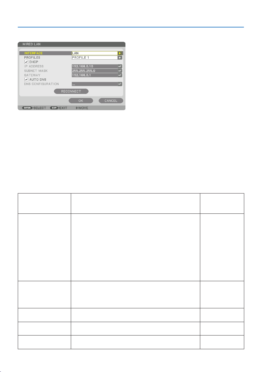
5. Using On-Screen Menu
143
WIRED LAN
When you select [WIRED LAN] in the on-screen menu for the first time after purchasing the projector,
the [NETWORK PASSWORD] setting screen will appear. Carry out the following Step (1) or Step (2).
(1) When setting the network password (recommended)
Refer to [NETWORK PASSWORD] (→ page 142).
(2) When no network password is set
Leave the 2 input fields in the [NETWORK PASSWORD] setting screen blank, then select [OK]
and press the ENTER button.
If [NETWORK PASSWORD] has been set, you cannot display the [WIRED LAN] screen without enter-
ing password.
INTERFACESelect[LAN] for using the LANportforconnectingtothewiredLAN.
Select[HDBaseT] for using the HDBaseTIN/Ethernet port for connecting
tothewiredLAN.
—
PROFILES•ThesettingsforthewiredLANcanberecordedintheprojector
memoryintwoways.
•Select[PROFILE1]or[PROFILE2]andthendosettingsfor[DHCP]and
theotheroptions.
Afterdoingthis,select[OK]andpresstheENTERbutton.Thiswillstore
yoursettingsinmemory.
•Torecallthesettingsfrommemory:
Afterselecting[PROFILE1]or[PROFILE2]fromthe[PROFILES]list.
Select[OK]andpresstheENTERbutton.
•Select[DISABLE]whennotconnectingtoawiredLAN
—
DHCPPlaceacheckmarktoautomaticallyassignanIPaddresstotheprojector
fromyourDHCPserver.
ClearthischeckboxtoregistertheIPaddressorsubnetmasknumber
obtainedfromyournetworkadministrator.
—
IPADDRESSSetyourIPaddressofthenetworkconnectedtotheprojectorwhen
[DHCP]isturnedo.
Up to 12 numeric
characters
SUBNETMASKSetyoursubnetmasknumberofthenetworkconnectedtotheprojector
when[DHCP]isturnedo.
Up to 12 numeric
characters
GATEWAYSetthedefaultgatewayofthenetworkconnectedtotheprojectorwhen
[DHCP]isturnedo.
Up to 12 numeric
characters
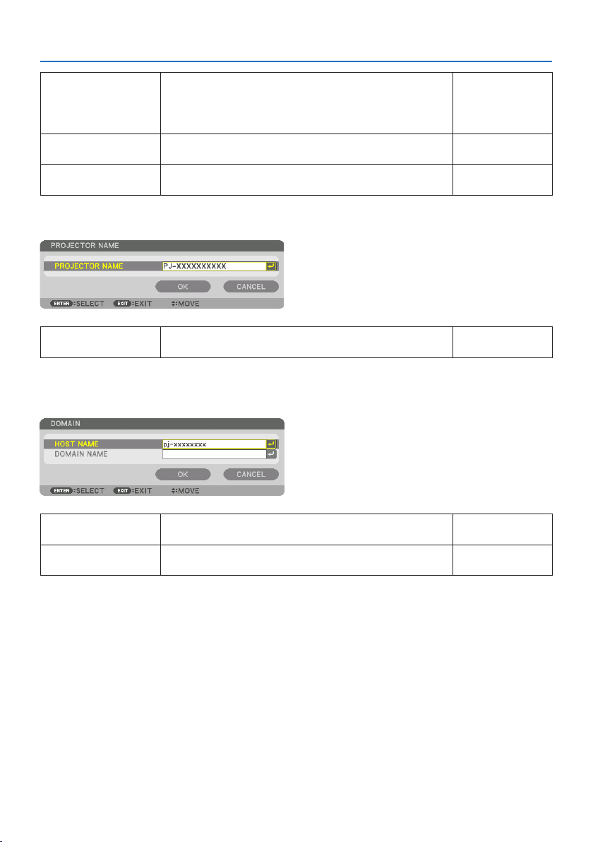
5. Using On-Screen Menu
144
AUTODNSPlaceacheckmarktoautomaticallyassigntheIPaddressofyourDNS
serverconnectedtotheprojectorfromyourDHCPserver.
ClearthischeckboxtosettheIPaddressofyourDNSserverconnectedto
theprojector.
Up to 12 numeric
characters
DNSCONFIGURATIONSettheIPaddressofyourDNSserveronthenetworkconnectedtothe
projectorwhen[AUTODNS]iscleared.
Up to 12 numeric
characters
RECONNECT Retrytoconnecttheprojectortoanetwork.Trythisifyouhavechanged
[PROFILES].
—
PROJECTOR NAME
PROJECTORNAMESetauniqueprojectorname.Up to 16 alphanumeric
charactersandsymbols
DOMAIN
Set a host name and domain name of the projector.
HOSTNAMESetahostnameoftheprojector.Up to 16 alphanumeric
characters
DOMAINNAMESetadomainnameoftheprojector.Up to 60 alphanumeric
characters
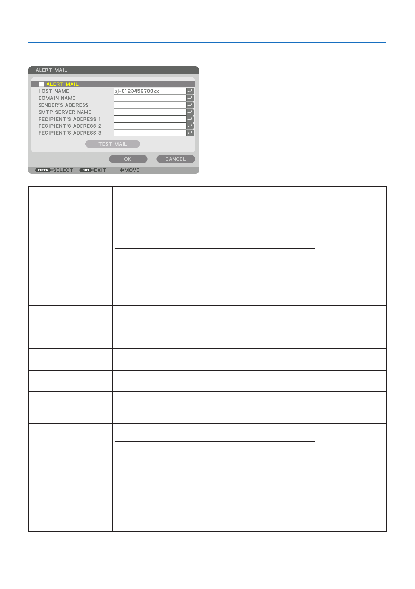
5. Using On-Screen Menu
145
ALERT MAIL
ALERTMAILThisoptionwillnotifyyourcomputeroferrormessagesviae-mailwhen
usingwirelessorwiredLAN.
PlacingacheckmarkwillturnontheAlertMailfeature.
ClearingacheckmarkwillturnotheAlertMailfeature.
Sampleofamessagetobesentfromtheprojector:
Subject:[Projector]ProjectorInformation
THE COOLING FAN HAS STOPPED.
[INFORMATION]
PROJECTOR NAME:xxxxx
LIGHT HOURS USED:xxxx[H]
—
HOSTNAMETypeinahostname.Up to 16 alphanumeric
characters
DOMAINNAMETypeinadomainnameofthenetworkconnectedtotheprojector.Up to 60 alphanumeric
characters
SENDER'SADDRESSSpecifythesender’saddress.Up to 60 alphanumeric
charactersandsymbols
SMTPSERVERNAMETypeintheSMTPservernametobeconnectedtotheprojector.Up to 60 alphanumeric
characters
RECIPIENT'SADDRESS1,
RECIPIENT'SADDRESS2,
RECIPIENT'SADDRESS3
Typeinyourrecipient’saddress.Up to 60 alphanumeric
charactersandsymbols
TESTMAILSendatestmailtocheckifyoursettingsarecorrect.
NOTE:
•Ifyouenteredanincorrectaddressinatest,youmaynotreceiveanAlert
mail.Shouldthishappen,checkiftheRecipient’sAddressiscorrectly
set.
•Unlessanyoneofthe[SENDER'SADDRESS],[SMTPSERVER'SNAME]or
[RECIPIENT'SADDRESS1-3]isselected,[TESTMAIL]isnotavailable.
•Besuretohighlight[OK]andpresstheENTERbuttonbeforeexecuting
[TESTMAIL].
—
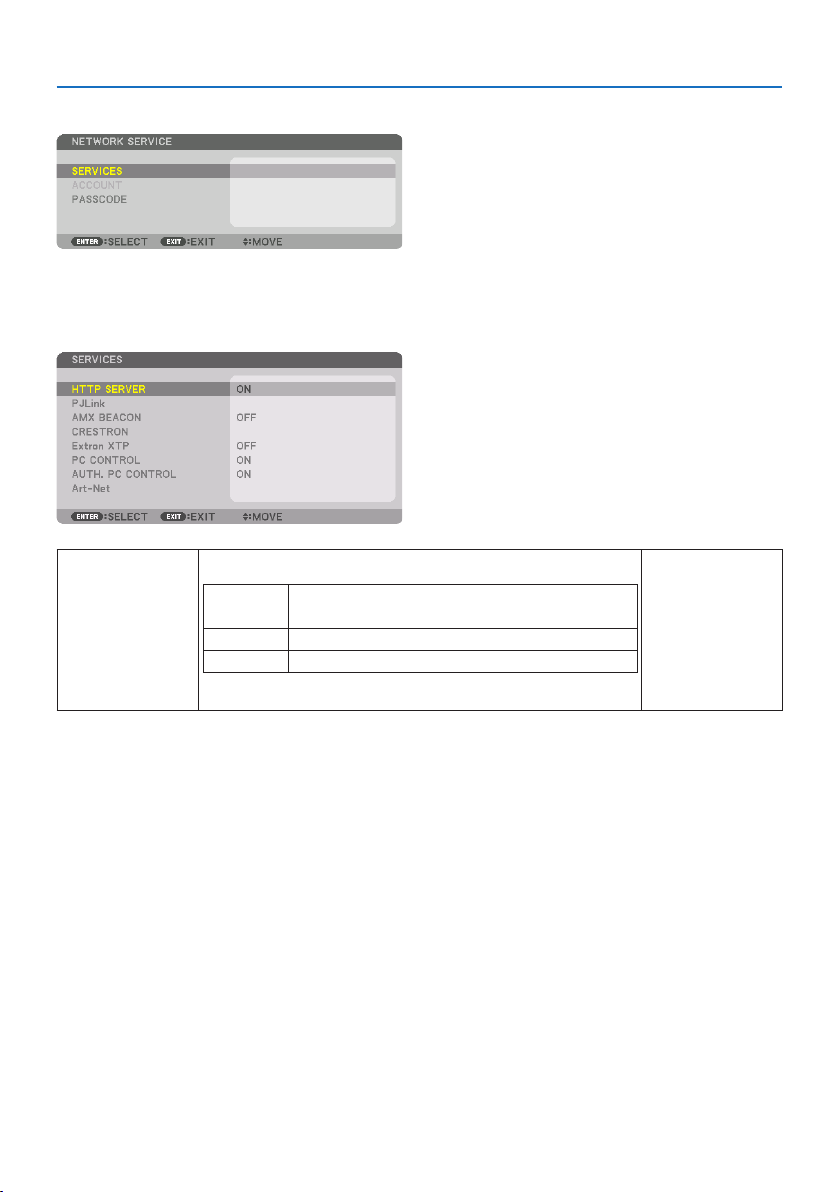
5. Using On-Screen Menu
146
[NETWORK SERVICE]
If [PASSCODE] has been set, you cannot display the [NETWORK SERVICE] screen without entering
PASSCODE.
[SERVICES]
HTTPSERVERCongurethesettingsforconnectingtotheHTTPserver.
ON ConnectdirectlytotheHTTPserverwithoutdisplayingthe
loginscreen.
OFFItisnotpossibletoconnecttotheHTTPserver.
AUTH.DisplaytheloginscreenwhenconnectingtotheHTTPserver.
EntertheUSERNAMEandPASSWORDthathavebeensetat[ACCOUNT].
—
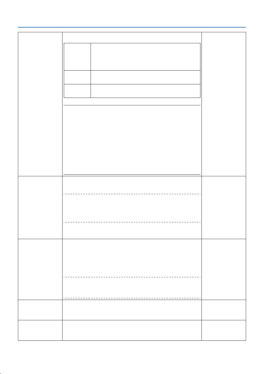
5. Using On-Screen Menu
147
PJLinkCongurethesettingsforusingPJLink.
NEW
PASSWORD,
CONFIRM
PASSWORD
Setthepassword.
CLASSTousefunctionswithPJLinkClass2specications,set
[CLASS2].
DESTINATIONWhenthe[CLASS]issetto[CLASS2],inputtheIPaddressof
thedestination.
NOTE:
•Donotforgetyourpassword.However,ifyouforgetyourpassword,consult
withyourdealer.
•WhatisPJLink?
PJLinkisastandardizationofprotocolusedforcontrollingprojectorsofdif-
ferentmanufacturers.ThisstandardprotocolisestablishedbyJapanBusiness
MachineandInformationSystemIndustriesAssociation(JBMIA)in2005.
TheprojectorsupportsallthecommandsofPJLinkClass1.
•SettingofPJLinkwillnotbeaectedevenwhen[RESET]isdonefromthe
menu.
Up to 32 alphanumeric
characters
AMXBEACONTurnonorofordetectionfromAMXDeviceDiscoverywhenconnectingtothe
networksupportedbyAMX’sNetLinxcontrolsystem.
TIP:
•WhenusingadevicethatsupportsAMXDeviceDiscovery,allAMXNetLinx
controlsystemwillrecognizethedeviceanddownloadtheappropriateDevice
DiscoveryModulefromanAMXserver.
[ON]willenabledetectingtheprojectorfromAMXDeviceDiscovery..
[OFF]willdisabledetectingtheprojectorfromAMXDeviceDiscovery.
—
CRESTRONROOMVIEW:TurnonorowhencontrollingtheprojectorfromyourPC.
CRESTRONCONTROL:Turnonorowhencontrollingtheprojectorfromyour
controller.
•CONTROLLERIPADDRESS:EnteryourIPaddressofCRESTRONSERVER.
•IPID:EnteryourIPID of CRESTRONSERVER.
TIP:
•TheCRESTRONsettingsarerequiredonlyforusewithCRESTRON ROOMVIEW.
Formoreinformation,visithttp://www.crestron.com
Up to 12 numeric
characters
ExtronXTPSetforconnectingthisprojectortotheExtronXTPtransmitter.
[ON]willenabletoconnectwiththeXTPtransmitter.
[OFF]willdisabletoconnectwiththeXTPtransmitter.
—
PCCONTROLSetthePCcontrolfunctiontoonoro.
[ON]willenablethePCcontrolfunction.
[OFF]willdisablethePCcontrolfunction.
—
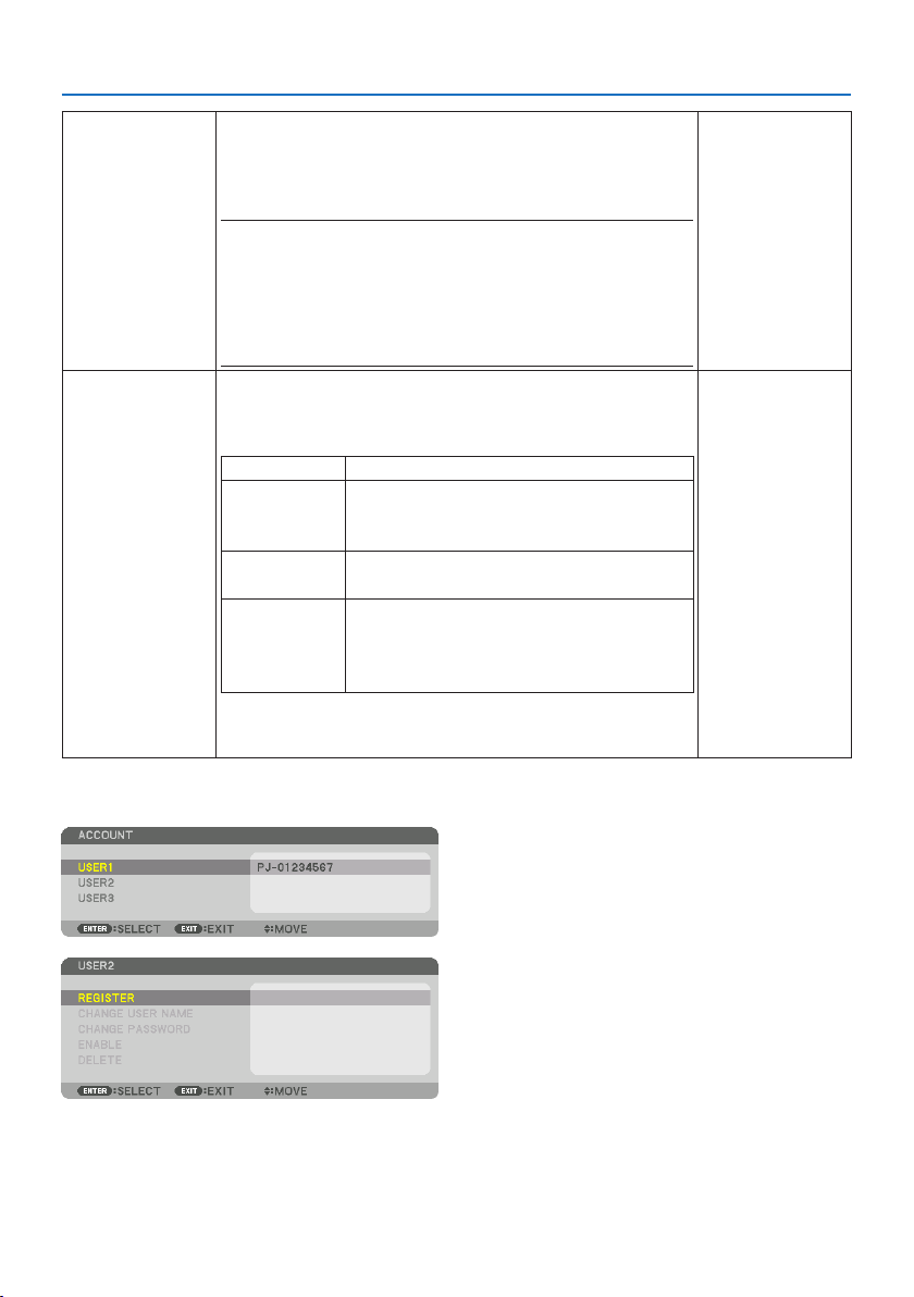
5. Using On-Screen Menu
148
AUTH.PCCONTROLSetPCcontrolfunctionusingauthenticationtoonoro.
[ON]willenablethePCcontrolfunctionwithauthenticationusingtheuser
nameandpasswordregisteredat[ACCOUNT].
[OFF]willdisablethePCcontrolfunctionwithauthentication.
NOTE:
•Thisfunctionisforfutureexpansion.Securitycanbeimprovedbyusing
togetherwithanapplicationcompatiblewiththeauthenticationfunction.
Forspecicationsrelatedtotheauthenticationprocedurerequiredbythe
applicationsoftware,pleasevisitourwebsite.
https://www.nec-display.com/dl/en/pj_manual/lineup.html
—
Art-NetArt-NetisacommunicationprotocolfortransmittingandreceivingDMX512
overanEthernetnetwork.
CongurethesettingsforcontrollingtheprojectorusingtheArt-Netcontroller.
Art-NetTurnsonoroArt-Net.
[2.X.X.X],
[10.X.X.X]
AutomaticallycalculatestheIPaddressaccordingtothe
Art-Netspecicationsandoverwritesittothecurrent
wiredLANsettings(IPaddress,subnetmask).
SETTINGSSetsDMXUniverseandstartchannelusedbythe
projector.
CHANNELSelectsprojectorfunctionstobeassignedtochannels
1thru12.Totemporarilydisabletheassignedfunction,
select[LOCK]tosettheparametertoanon-operable
value.
•ThefunctionandDMXvaluesetforeachchannelcanbecheckedin[INFO.].
•See“Art-NetDMXParameterList”(→ page
201)fortheDMXparameters.
—
[ACCOUNT]
Youcanregisterthreetypesofaccounts:[USER1], [USER2], and [USER3].
When [PASSCODE] is set, [REGISTER] is enabled for each user.
[CHANGE USER NAME], [CHANGE PASSWORD], [ENABLE], and [DELETE] can be selected once the
account has been registered at [REGISTER].

5. Using On-Screen Menu
149
REGISTERSettheusernameandpasswordoftheaccountforusewith[HTTP
SERVER]authenticationand[AUTH.PCCONTROL].
Up to 16 alphanumeric
characters
CHANGEUSERNAMEChangetheusernameregisteredat[ACCOUNT].Up to 16 alphanumeric
characters
CHANGEPASSWORDChangethepasswordregisteredat[ACCOUNT].Up to 16 alphanumeric
characters
ENABLEChoosewhethertoenableordisabletheaccount.
[ON]willenabletheaccount.
[OFF]willdisabletheaccount.Withthisaccount,youcannotconnectto
anHTTPserverthatrequiresauthenticationoroperatetheprojectorusing
the[AUTH.PCCONTROL]function.
—
DELETE DeletetheUSERNAMEandPASSWORDthathavebeensetat[ACCOUNT].
NOTE:
•Ifthe[USER1],[USER2],and[USER3]accountshaveallbeendeleted,
youcannotconnecttotheHTTPserverthatrequiresauthenticationor
operatetheprojectorusingthe[AUTH.PCCONTROL]function.
—
[PASSCODE]
Setthepasscodeforthenetworkadministrator.
Whenthepasscodeisset,aconrmationscreenisdisplayedwhenopeningthe[NETWORKSERVICE]
screenoftheon-screenmenuandthe[SERVICES]taboftheHTTPserver,andthepasscodemustbe
input.
Setthepasscodeusingacombinationofthe▼▲◀▶buttonsonthemainunitortheremotecontrol.
Todeletethepasscode,registerwiththe[PASSCODE]entryeldblank.
NOTE:
•Makeanoteofyourpasscodeandstoreitinasafeplace.
•Ifyouforgetyourpasscode,contactyourdistributor.
Up to 10 alphanumeric
characters
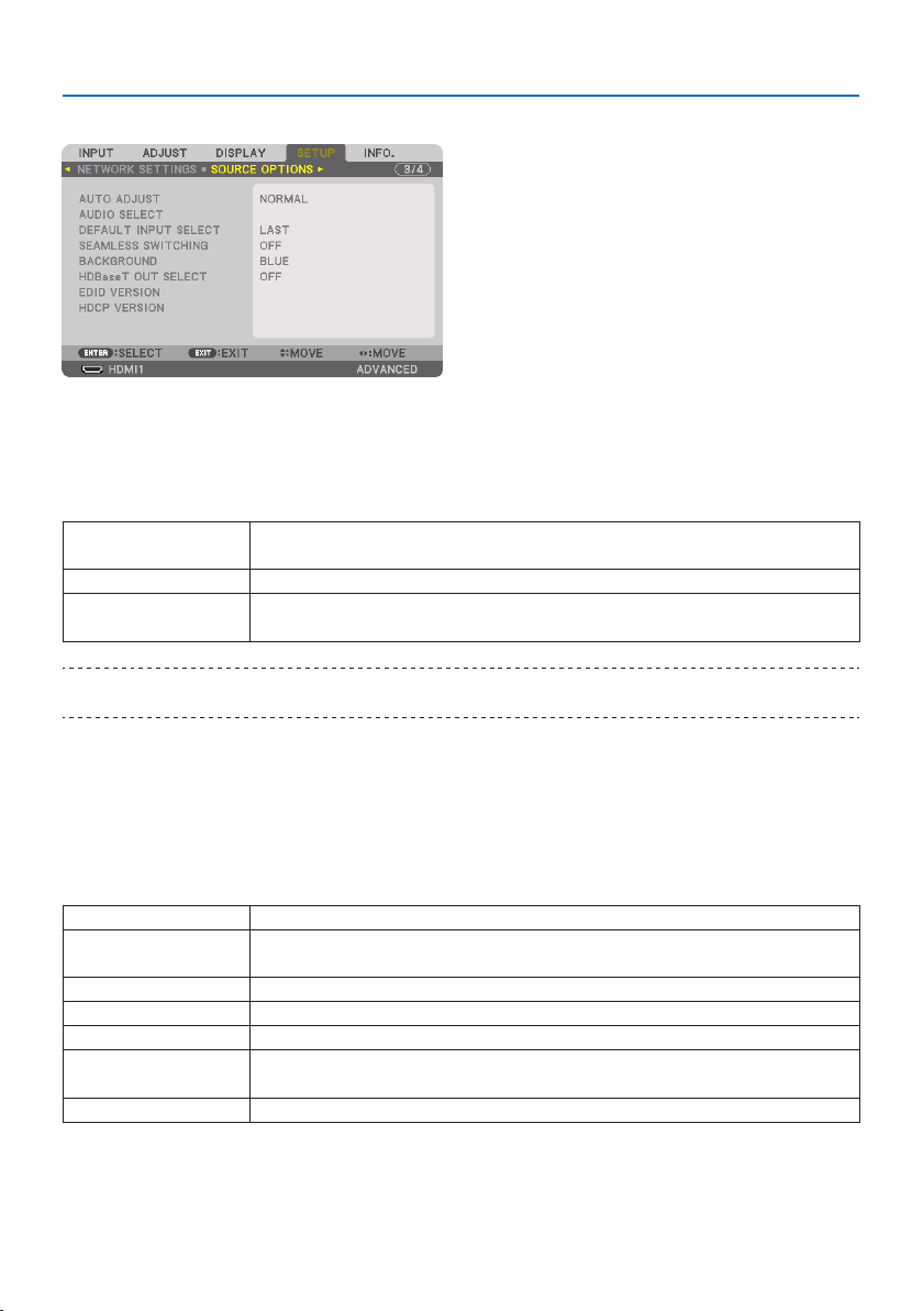
5. Using On-Screen Menu
150
[SOURCE OPTIONS]
SettingAutoAdjust[AUTO ADJUST]
This feature sets the Auto Adjust mode so that the computer signal can be automatically or manually
adjustedfornoiseandstability.Youcanautomaticallymakeadjustmentintwoways:[NORMAL]
and [FINE].
OFFThecomputersignalwillnotbeautomaticallyadjusted.Youcanmanuallyoptimizethecomputer
signal.
NORMALDefaultsetting.Thecomputersignalwillbeautomaticallyadjusted.Normallyselectthisoption.
FINESelectthisoptionifneadjustmentisneeded.Ittakesmoretimetoswitchtothesourcethanwhen
[NORMAL]isselected.
TIP:
•Thedefaultsettingwhenshippedfromthefactoryis[NORMAL].
[AUDIO SELECT]
This selects the audio input of the HDMI 1 IN terminal, HDMI 2 IN terminal, DisplayPort IN terminal
and HDBaseT IN/Ethernet port.
SelectingDefaultSource[DEFAULT INPUT SELECT]
You can set the projector to default to any one of its inputs each time the projector is turned on.
LASTSetstheprojectortodefaulttothepreviousorlastactiveinputeachtimetheprojectoristurnedon.
AUTOSearchesforanactivesourceinorderofHDMI1 → HDMI2 → DisplayPort → COMPUTER →
HDBaseTanddisplaystherstfoundsource.
HDMI1DisplaysthedigitalsourcefromtheHDMI1INconnectoreverytimetheprojectoristurnedon.
HDMI2DisplaysthedigitalsourcefromtheHDMI2INconnectoreverytimetheprojectoristurnedon.
DisplayPortDisplaysthedigitalsourcefromtheDisplayPorteverytimetheprojectoristurnedon.
COMPUTERDisplaysthecomputersignalfromtheCOMPUTERINconnectoreverytimetheprojectoristurned
on.
HDBaseT ProjecttheHDBaseTsignal.
[SEAMLESS SWITCHING]
When the input connector is switched, the image displayed before switching is held to switch to
the new image without a break due to absence of a signal.

5. Using On-Screen Menu
151
SelectingaColororLogoforBackground[BACKGROUND]
Use this feature to display a blue/black screen or logo when no signal is available. The default
background is [BLUE].
NOTE:
•Evenwhenthebackgroundlogoisselected,iftwopicturesaredisplayedin[PIP/PICTUREBYPICTURE]mode,thebluebackground
isdisplayedwithoutthelogowhenthereisnosignal.
[HDBaseT OUT SELECT]
Select signal to output from the HDBaseT OUT/Ethernet port on the projector.
OFFNosignalisoutput.
AUTOOutputtheinputsignal.Whentwoimagesareprojectedsimultaneously(PIP/PICTUREBYPICTURE),
theimageforthemainscreenisoutput.
HDMI1Output the input signal thru the HDMI1INterminal.
HDMI2Output the input signal thru the HDMI2INterminal.
DisplayPortOutput the input signal thru the DisplayPortINterminal.
HDBaseT Output the input signal thru the HDBaseTIN/Ethernetport.
NOTE:
•SignalthrutheCOMPUTERINterminalcannotbeoutput.Inthestate[PIP]or[PICTUREBYPICTURE]hasbeensetand[AUTO] has
beensetforthisfunction,moreover,theinputterminalforthemainscreenistheCOMPUTERandtheinputterminalforthesub
screen is one among the HDMI1IN,HDMI2IN,DisplayPortINterminals,orHDBaseTIN/Ethernetport,thesignalfromthesub
screenwillbeoutput.
•Ifthesetinputterminalsformainandsubscreenfor[PIP]and[PICTUREBYPICTURE]aredieredfromtheselectedinputterminals,
anyimagewillbeoutput.
•4K60pand4K50psignalscannotbeoutput.
[EDID VERSION]
Switch the EDID version for the HDMI 1 IN and HDMI 2 IN terminals.
MODE1 Supportsgeneralsignal
MODE2 Supports4Ksignal
Selectthismodefordisplaying4Kimageusingthedevicesupporting4K
NOTE:
•Ifimageandsoundcannotbeoutputin[MODE2],switchto[MODE1].

5. Using On-Screen Menu
152
[HDCP VERSION]
Switch the HDCP version for the HDMI 1 IN, HDMI 2 IN and HDBaseT IN/Ethernet terminals.
HDCP2.2AutomaticallyswitchthemodeHDCP2.2andHDCP1.4
HDCP1.4ForcedlyperformtransmissionwithHDCP1.4
NOTE:
•IfimageandsoundcannotbeoutputfromthemonitorconnectedwiththeHDBaseT OUT/Ethernetport,switchtheHDCPversion
to HDCP1.4.
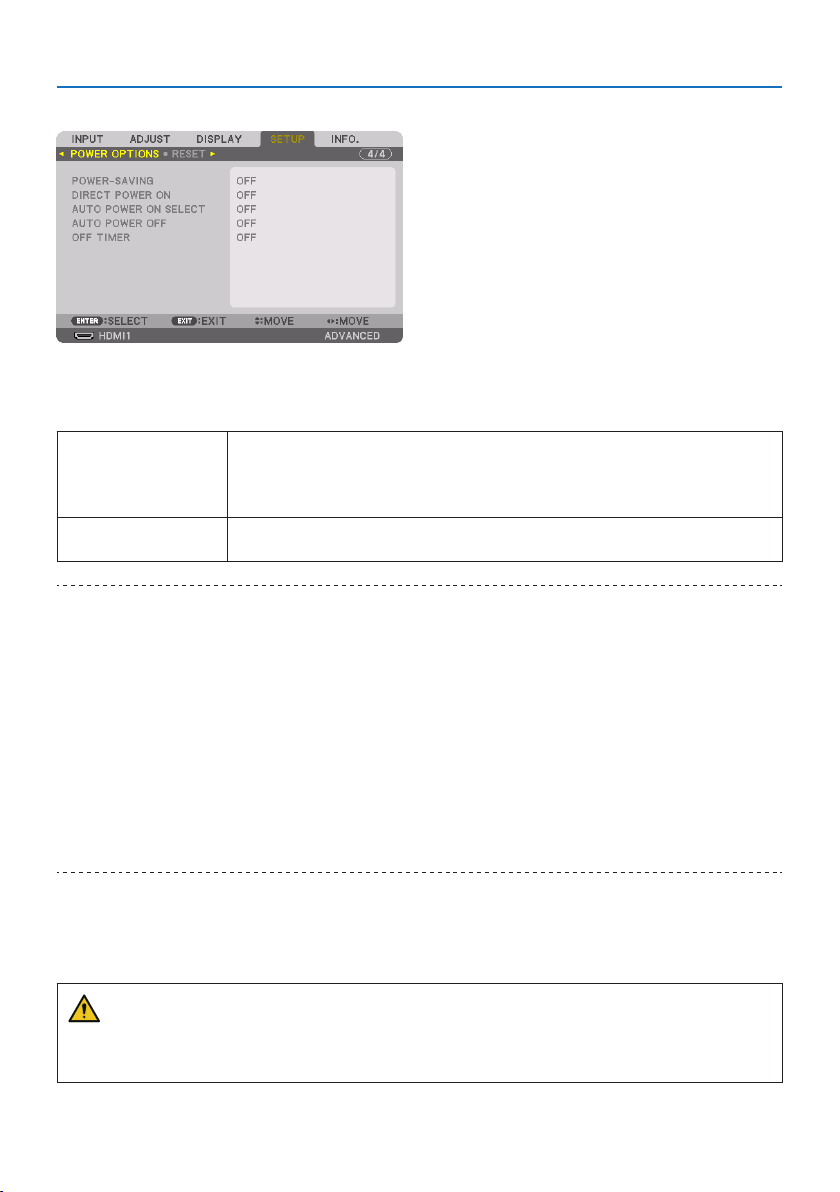
5. Using On-Screen Menu
153
[POWER OPTIONS]
[POWER-SAVING]
Selectthestandbymode:
ON Thissettingistokeepthestandbypowerconsumptiontotheminimumnecessary.
Thestandbystatechangesautomaticallydependingontheprojectorsettingsandthestateand
durationofconnecteddevices(→ page 191).Theconsumptionpoweralsochangesaccordingto
thestandbystate.
OFFThisisasettingwithnofunctionalrestrictionsduringstandby.
Tomaintainthesleepstate,thepowerconsumptionishigherthanwhenthismodeissetto[ON].
TIP:
•Evenif[POWER-SAVING]issetto[ON],theprojectorgoestosleepinthefollowingcases.
-[PCCONTROL(HDBaseT)]issetto[ON]
-[REMOTESENSOR]issetto[HDBaseT]
-[HDBaseTOUTSELECT]issettootherthan[OFF]
-When[AUTOPOWERONSELECT]issettosomethingotherthan[OFF]andasignalisbeinginputtotheHDMI1,HDMI2,DisplayPort
or COMPUTER terminal
-[WIREDLAN] →[INTERFACE]issetto[HDBaseT]
-[ExtronXTP]issetto[ON]
-Whilethelensismoving
-Whenatemperatureerrororothererrorhasoccurred
•The[POWER-SAVING]settingisnotchangedby[RESET].
•[POWER-SAVING] ON/OFFdoesnotaectthecarbonmeter’scalculationoftheamountofCO
2
emissionreduction.
EnablingDirectPowerOn[DIRECT POWER ON]
Turns the projector on automatically when the power cord is inserted into an active power outlet.
This eliminates the need to always use the POWER button on the remote control or projector cabinet.
WARNING
• Theprojectorproducesintenselight.Whenturningonthepower,makesurenoonewithin
the projection range is looking at the lens.

5. Using On-Screen Menu
154
TurningOntheProjectorbyDetectingInputSignal[AUTO POWER ON SELECT]
Under the state of standby or sleep, the projector automatically detects and projects synchronizing
signal input from the selected terminals among [COMPUTER], [HDMI1], [HDMI2], [DisplayPort], and
[HDBaseT] by this function.
OFF[AUTOPOWERONSELECT]functionbecomesinactive.
HDMI1,HDMI2,DisplayPort,
COMPUTER,HDBaseT*
Whentheprojectordetectsthecomputersignalinputfromtheselectedterminal,automaticallyit
willbeturned[ON]andwillprojectthecomputerscreen.
WARNING
• Theprojectorproducesintenselight.Whenthepoweristurnedon,makesurenoonewithin
the projection range is looking at the lens.
NOTE:
•Ifyouwanttoactivatethis[AUTOPOWERONSELECT]functionafterpoweringOFFtheprojector,interruptthesignalfromtheinput
terminalsordisconnectthecomputercablefromtheprojectorandwaitformorethan3seconds(1minuteorlongeriftheinput
signal is HDBaseT)andthentheinputsignalfromtheselectedterminal.Inaddition,ifsignalfromHDMI1,HDMI2,DisplayPort or
HDBaseTiscontinuouslyinputtotheprojector,theprojectormaybeturnedONagainautomaticallybasedonthesettingofexternal
deviceseveniftheprojectoristurnedOFFandintheconditionofSLEEPmode.
•Thisfunctionisnotactivatedeitherbycomponentsignalinputfromthecomputerscreeninputterminalorcomputersignalas
SynconGreenandCompositeSync.
EnablingPowerManagement[AUTO POWER OFF]
When this option is selected you can enable the projector to automatically turn off (at the selected
time:0:05,0:10,0:15,0:20,0:30,1:00)ifthereisnosignalreceivedbyanyinputorifnooperation
is performed.
UsingOTimer[OFF TIMER]
1. Select your desired time between 30 minutes and 16 hours: OFF, 0:30, 1:00, 2:00, 4:00,
8:00, 12:00, 16:00.
2. Press the ENTER button on the remote control.
3. The remaining time starts counting down and it is displayed at the bottom of the On-Screen
Menu.
4.Theprojectorwillturnoafterthecountdowniscomplete.
NOTE:
•Tocancelthepresettime,set[OFF]forthepresettimeorturnothepower.
•Whentheremainingtimereaches3minutesbeforetheprojectoristurnedo,the[THEPROJECTORWILLTURNOFFWITHIN3
MINUTES.]messagewillbedisplayedonthebottomofthescreen.
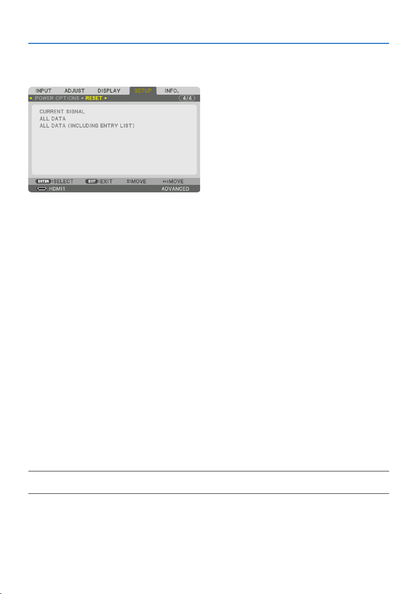
5. Using On-Screen Menu
155
Returning to Factory Default [RESET]
The [RESET] feature allows you to change adjustments and settings to the factory preset for a (all)
source(s)exceptthefollowing:
[CURRENT SIGNAL]
Resets the adjustments for the current signal to the factory preset levels.
Theitemsthatcanberesetare:[PRESET], [CONTRAST], [BRIGHTNESS], [COLOR], [HUE], [SHARPNESS],
[ASPECT RATIO], [HORIZONTAL], [VERTICAL], [CLOCK], [PHASE], and [OVERSCAN].
[ALL DATA]
Reset all the adjustments and settings for all the signals to the factory preset.
All items can be reset EXCEPT [ENTRY LIST], [GEOMETRIC CORRECTION], [EDGE BLENDING], [PICTURE
SETTING], [MULTI SCREEN], [LANGUAGE], [SCREEN], [FAN MODE], [REF. WHITE BALANCE], [STATIC
CONVERGENCE], [REF. LENS MEMORY], [COLOR UNIFORMITY(TOOL)], [GAMMA(TOOL)], [ADMINISTRA-
TOR MODE], [DATE AND TIME SETTINGS], [CONTROL PANEL LOCK], [SECURITY], [COMMUNICATION
SPEED], [PC CONTROL(HDBaseT)], [CONTROL ID], [NETWORK SETTINGS], [BACKGROUND], [EDID
VERSION], [HDCP VERSION], [POWER-SAVING], [OFF TIMER], [LIGHT HOURS USED], and [TOTAL
CARBON SAVINGS].
[ALL DATA (INCLUDING ENTRY LIST)]
Reset all the adjustments and settings for all the signals including the [ENTRY LIST] to the fac-
tory preset except [GEOMETRIC CORRECTION], [EDGE BLENDING], [PICTURE SETTING], [MULTI
SCREEN], [LANGUAGE], [SCREEN], [FAN MODE], [REF. WHITE BALANCE], [STATIC CONVERGENCE],
[REF. LENS MEMORY], [COLOR UNIFORMITY(TOOL)], [GAMMA(TOOL)], [ADMINISTRATOR MODE],
[DATE AND TIME SETTINGS], [CONTROL PANEL LOCK], [SECURITY], [COMMUNICATION SPEED], [PC
CONTROL(HDBaseT)], [CONTROL ID], [NETWORK SETTINGS], [BACKGROUND], [EDID VERSION], [HDCP
VERSION], [POWER-SAVING], [OFF TIMER], [LIGHT HOURS USED], and [TOTAL CARBON SAVINGS].
Also deletes all the signals in the [ENTRY LIST] and returns to the factory preset.
NOTE:
•LockedsignalsinEntryListcannotbereset.
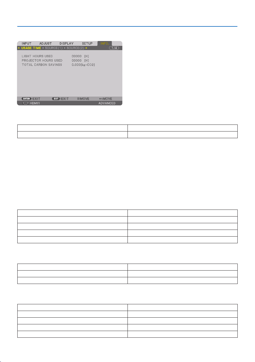
5. Using On-Screen Menu
156
5-8. Menu Descriptions & Functions [INFO.]
[USAGE TIME]
LIGHTHOURSUSED (H) PROJECTORHOURSUSED (H)
TOTALCARBONSAVINGS(kg-CO2)
•Thevalueof[LIGHT HOURS USED] reflects the temperature of the operating environment and
the [LIGHT MODE] setting in the actual operating time.
•[PROJECTOR HOURS USED]
This displays the actual operating time of the projector.
•[TOTAL CARBON SAVINGS]
This displays the estimated carbon saving information in kg. The carbon footprint factor in the
carbon saving calculation is based on the OECD (2008 Edition). (→ page
44)
[SOURCE(1)]
INPUTTERMINALRESOLUTION
HORIZONTALFREQUENCYVERTICALFREQUENCY
SYNCTYPESYNCPOLARITY
SCANTYPESOURCENAME
ENTRYNO.
[SOURCE(2)]
SIGNALTYPEBITDEPTH
VIDEOLEVELSAMPLINGFREQUENCY
3DFORMAT
[SOURCE(3)]
INPUTTERMINALRESOLUTION
HORIZONTALFREQUENCYVERTICALFREQUENCY
SYNCTYPESYNCPOLARITY
SCANTYPESOURCENAME
ENTRYNO.
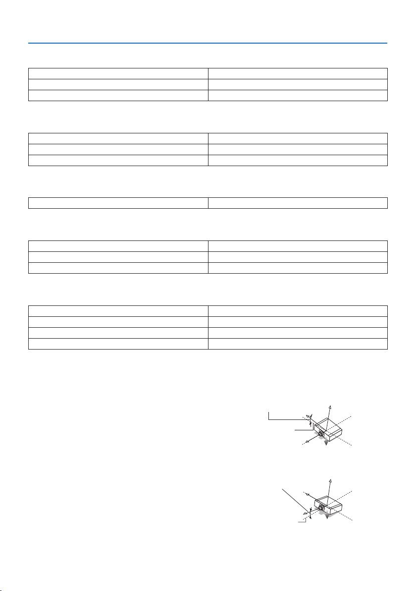
5. Using On-Screen Menu
157
[SOURCE(4)]
SIGNALTYPEBITDEPTH
VIDEOLEVELSAMPLINGFREQUENCY
3DFORMAT
[WIRED LAN]
IPADDRESSSUBNETMASK
GATEWAYMACADDRESS
DNS
[VERSION]
SOFTWARE
[OTHERS]
DATETIMEPROJECTORNAME
MODELNO.SERIALNUMBER
LENSID
[CONDITIONS]
INTAKETEMPERATUREEXHAUSTTEMPERATURE
ATMOSPHERICPRESSUREINSTALLATIONPOSITION
X-AXISY-AXIS
Z-AXISOPTIONCOVER
Aboutthe[X-AXIS],[Y-AXIS],and[Z-AXIS]under[CONDITIONS]
* Arrow direction of the Z-AXIS in the figure represents the top of the projector.
X-AXIS:
Displaytheprojectorimageatanangleof−100–
+100 degrees to the horizontal in the X-axis direction.
X-AXIS value of
the projector
Horizontal plane
X-axis
Gravity direction
Y-AXIS:
Displaytheprojectorimageatanangleof−100–
+100 degrees to the horizontal in the Y-axis direction.
Y-AXIS value of
the projector
Horizontal plane
Y-axis
Gravity direction
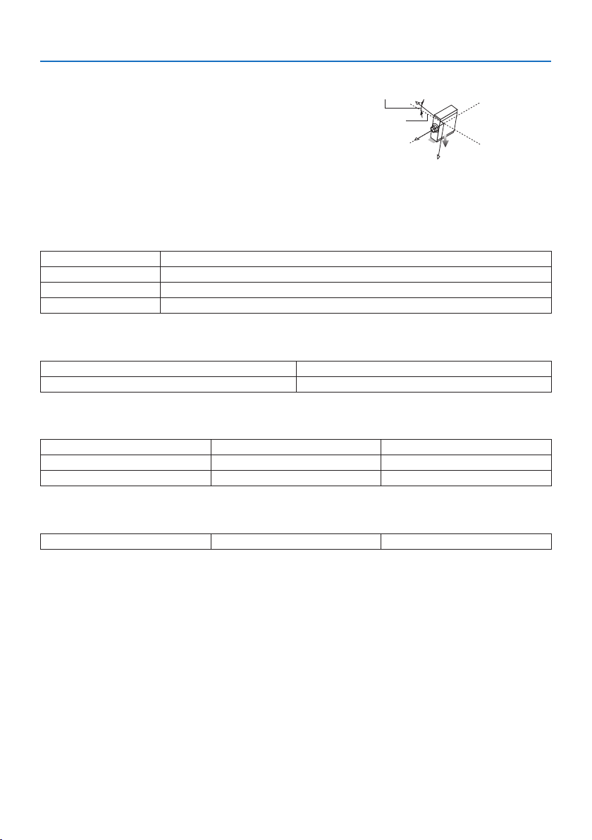
5. Using On-Screen Menu
158
Z-AXIS:
Displaytheprojectorimageatanangleof−100–
+100 degrees to the vertical in the Z-axis direction.
Z-AXIS value of
the projector
Horizontal
plane Z-axis
Gravity direction
About[OPTION COVER]
This is used to check whether the option cover (separately sold) needs to be attached when the
projector is installed at an angle.
- / - Optioncoverisnotrequired
A/-OnlyoptioncoverAneedstobeattached
- / B OnlyoptioncoverBneedstobeattached
A/BBothofoptioncoversAandBneedtobeattached
[HDBaseT]
SIGNALQUALITYOPERATIONMODE
LINKSTATUSHDMISTATUS
[Art-Net(1)]
Ch1 Ch2 Ch3
Ch4Ch5 Ch6
Ch7 Ch8 Ch9
[Art-Net(2)]
Ch10 Ch11 Ch12

159
CAUTION
•Besuretoturnotheprojectorbeforeconnectingtheprojectortoanexternaldevice.If
projected light enters your eyes, it may cause visual impairment.
NOTE:
•Theconnectioncableisnotenclosedwiththeprojector.Pleasegetreadyasuitablecablefortheconnection.
ForHDMI,DisplayPort,LAN,RS-232C,andAUDIO,pleaseuseashieldedsignalcable.
For15-pinminiD-Sub,pleaseuseashieldedsignalcablewithferritecore.
Useofothercablesandadaptersmaycauseinterferencewithradioandtelevisionreception.
6. Connecting to Other Equipment
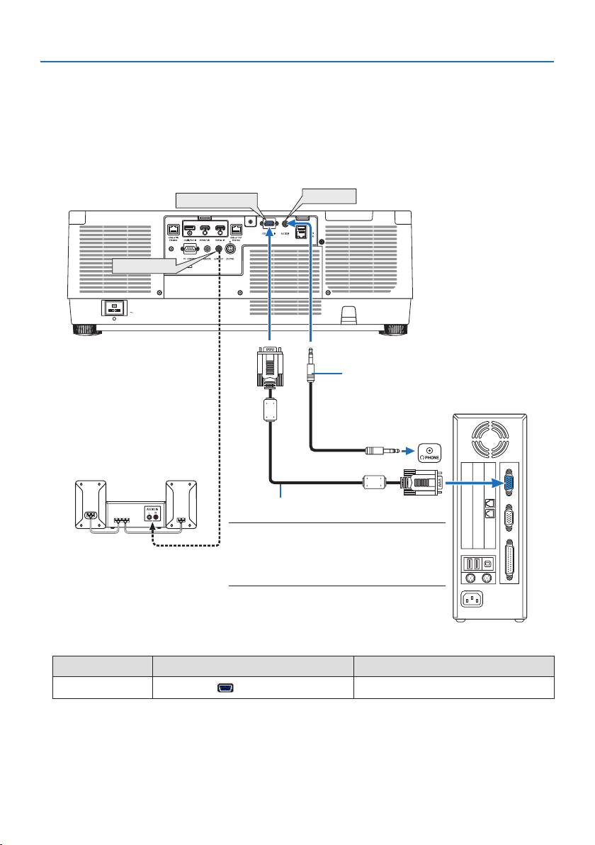
6. Connecting to Other Equipment
160
6-1. Connecting Your Computer
A computer cable, HDMI cable, or a DisplayPort cable can be used to connect to a computer.
Analog RGB signal connection
•Connectthecomputercabletothemonitoroutterminal(miniD-sub15pin)onthecomputer
and the computer video input terminal on the projector. Please use a computer cable attached
with a ferrite core.
COMPUTER IN
AUDIO OUT
AUDIO IN
Computer cable (sold commercially)
NOTE:
•Pleasechecktheoperatingmanualofthecomputer
asthename,positionanddirectionoftheterminal
maydierdependingonthecomputer.
Stereo mini-plug audio cable (not supplied)
•Selectthesourcenameforitsappropriateinputconnectorafterturningontheprojector.
Input connector INPUT button on the projector cabinet Button on the remote control
COMPUTER IN
COMPUTER
COMP.
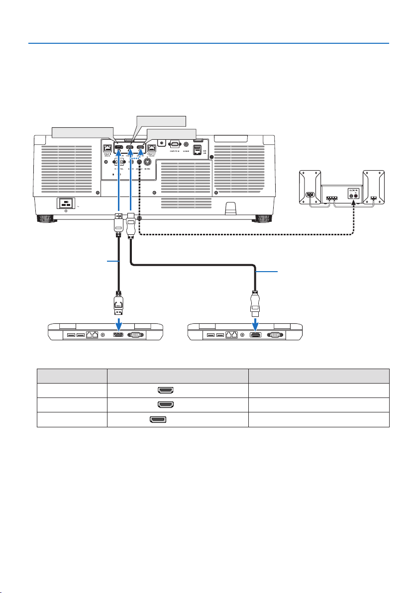
6. Connecting to Other Equipment
161
Digital RGB signal connection
•ConnectacommerciallyavailableHDMIcablebetweenthecomputer’sHDMIoutputconnector
and the projector’s HDMI 1 IN or HDMI 2 IN connector.
•ConnectacommerciallyavailableDisplayPort cable between the computer’s DisplayPort output
connector and the projector’s DisplayPort input connector.
DisplayPort IN
HDMI 1 IN
HDMI 2 IN
HDMI cable (not supplied)
DisplayPort cable
(not supplied)
•Selectthesourcenameforitsappropriateinputconnectorafterturningontheprojector.
Input connector INPUT button on the projector cabinet Button on the remote control
HDMI 1 IN
HDMI1 HDMI1
HDMI 2 IN
HDMI2 HDMI2
DisplayPort IN
DisplayPort
DP1
Cautions when connecting an HDMI cable
•UseacertiedHighSpeedHDMI®CableorHighSpeedHDMI®CablewithEthernet.

6. Connecting to Other Equipment
162
Cautions when connecting a DisplayPort cable
•UseacertiedDisplayPort cable.
•Dependingonthecomputer,sometimemayberequireduntiltheimageisdisplayed.
•SomeDisplayPort cables (commercially available) have locks.
•Todisconnectthecable,pressthebuttononthetopofthecable’sconnector,thenpullthecable
out.
•IncasepowersupplyfromtheDisplayPort IN terminal is required, please contact your dealer.
•WhensignalsfromadevicethatusesasignalconverteradapterareconnectedtotheDisplayPort
input connector, the picture may not appear or may not be displayed normally.
•WhentheHDMIoutputofacomputerisconnectedtotheDisplayPort input connector, use a
converter (commercially available).
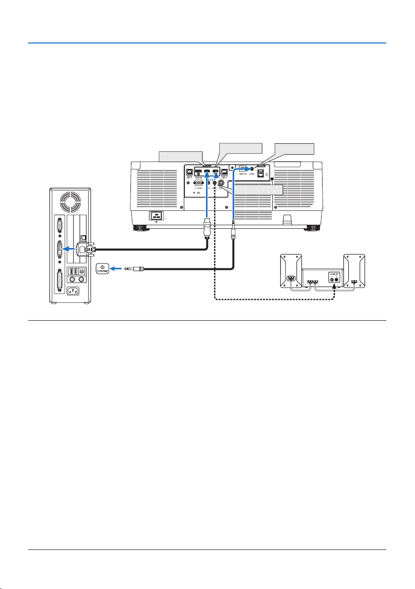
6. Connecting to Other Equipment
163
Cautions when using a DVI signal
•WhenthecomputerhasaDVIoutputconnector,useacommerciallyavailableconvertercable
to connect the computer to the projector’s HDMI 1 IN or HDMI 2 IN connector (only digital video
signals can be input). Also, connect the computer’s audio output to the projector’s audio input
connector. In this case, switch the HDMI1 or HDMI2 setting at on-screen menu’s audio selection
on the projector to [COMPUTER]. (→ page
150)
To connect the computer’s DVI output connector to the projector’s DisplayPort input connector,
use a commercially available converter.
HDMI 1 IN
HDMI 2 IN AUDIO IN
AUDIO OUT
NOTE:
•Turnothepowerofthecomputerandprojectorbeforeconnecting.
•Whenconnectingtheheadphoneterminalofthecomputertotheaudioinputterminaloftheprojectorwithanaudiocable,set
thecomputervolumetoalowlevelbeforeconnecting.Thenadjustthevolumeoftheprojectorandthevolumeofthecomputer
alternatelytosetthevolumetoasuitablelevel.
•Ifthecomputerhasamini-jacktypeaudiooutputconnector,werecommendconnectingtheaudiocabletothatconnector.
•Whenavideodeckisconnectedviaascanconverter,etc.,thedisplaymaynotbecorrectduringfast-forwardingandrewinding.
•UseaDVI-to-HDMIcablecompliantwithDDWG(DigitalDisplayWorkingGroup)DVI(DigitalVisualInterface)revision1.0standard.
Thecableshouldbewithin197"/5mlong.
•TurnotheprojectorandthePCbeforeconnectingtheDVI-to-HDMIcable.
•ToprojectaDVIdigitalsignal:Connectthecables,turntheprojectoron,thenselecttheHDMIinput.Finally,turnonyourPC.
Failuretodosomaynotactivatethedigitaloutputofthegraphicscardresultinginnopicturebeingdisplayed.Shouldthishappen,
restartyourPC.
•SomegraphicscardshavebothanalogRGB(15-pinD-Sub)andDVI(orDFP)outputs.Useofthe15-pinD-Subconnectormayresult
innopicturebeingdisplayedfromthedigitaloutputofthegraphicscard.
•DonotdisconnecttheDVI-to-HDMIcablewhiletheprojectorisrunning.Ifthesignalcablehasbeendisconnectedandthenrecon-
nected,animagemaynotbecorrectlydisplayed.Shouldthishappen,restartyourPC.
•TheCOMPUTERINvideoinputconnectorssupportWindowsPlugandPlay.
•AMacsignaladapter(commerciallyavailable)mayberequiredtoconnectaMaccomputer.
ToconnectaMaccomputerequippedwithaMiniDisplayPorttotheprojector,useacommerciallyavailableMiniDisplayPort →
DisplayPortconvertercable.
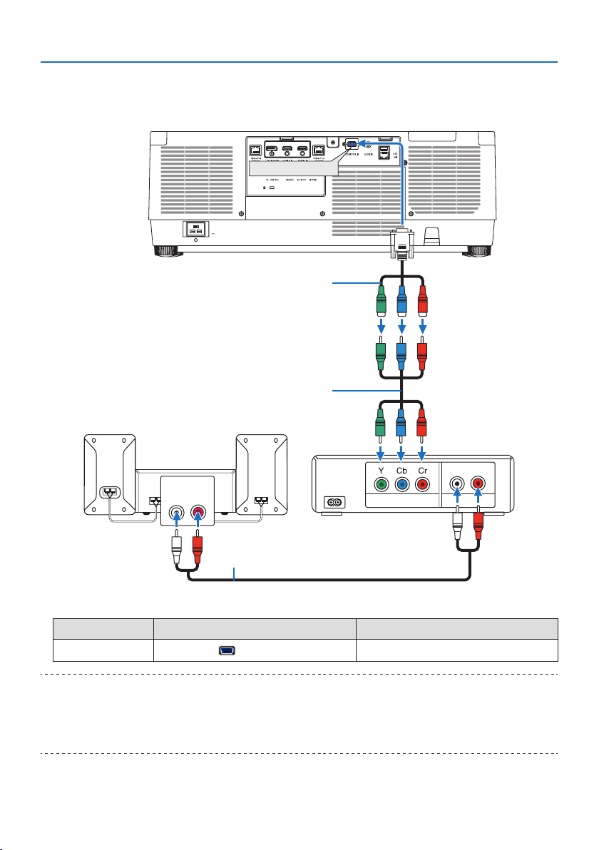
6. Connecting to Other Equipment
164
6-2. Connecting to a DVD player and other AV devices
Connecting Component Input
AUDIO OUT
AUDIO IN
LR
LR
COMPUTER IN
Component
15-pin-to-RCA(female)×3cableadapter(ADP-CV1E)
Stereo mini plug - to - RCA audio cable
(not supplied)
ComponentvideoRCA×3cable(notsupplied)
Blu-ray player
Audio Equipment
•Selectthesourcenameforitsappropriateinputconnectorafterturningontheprojector.
Input connector INPUT button on the projector cabinet Button on the remote control
COMPUTER IN
COMPUTER
COMP.
TIP:
•Whenthesignalformatissetto[AUTO](defaultfactorysettingwhenshipped),thecomputersignalandcomponentsignalare
automaticallydistinguishedandswitched.Ifthesignalscannotbedistinguished,selecttheappropriatesettingunder[ADJUST]
→[VIDEO] →[SIGNALTYPE]intheon-screenmenuoftheprojector.
•ToconnecttoavideodevicewithaDconnector,usethesoldseparatelyDconnectorconverteradapter(modelADP-DT1E).
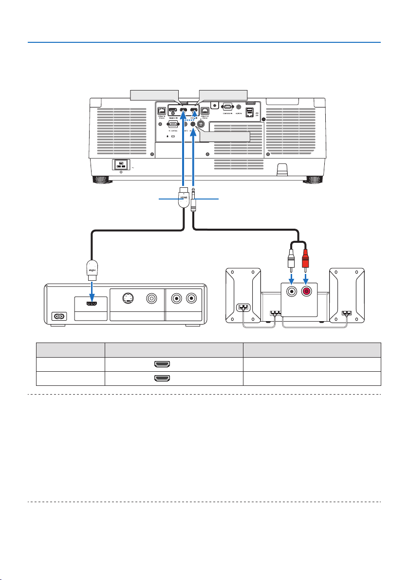
6. Connecting to Other Equipment
165
Connecting HDMI Input
You can connect the HDMI output of your Blu-ray player, hard disk player, or notebook type PC to
the HDMI 1 IN or HDMI 2 IN connector of your projector.
HDMI 1 IN HDMI 2 IN
AUDIO OUT
VIDEO OUT
VIDEO
LR
LR
S-VIDEO
HDMI OUT AUDIO OUT
AUDIO IN
Audio cable (not supplied)HDMI cable (not supplied)
UseHighSpeedHDMI®Cable.
Input connector INPUT button on the projector cabinet Button on the remote control
HDMI 1 IN
HDMI1 HDMI1
HDMI 2 IN
HDMI2 HDMI2
TIP:
•ForusersofaudiovideoequipmentwithanHDMIconnector:
Select“Enhanced”ratherthan“Normal”ifHDMIoutputisswitchablebetween“Enhanced”and“Normal”.
Thiswillprovideimprovedimagecontrastandmoredetaileddarkareas.
Formoreinformationonsettings,refertotheinstructionmanualoftheaudiovideoequipmenttobeconnected.
•WhenconnectingtheHDMI1IN or HDMI2INconnectoroftheprojectortotheBlu-rayplayer,theprojector’svideolevelcanbe
madesettingsinaccordancewiththeBlu-rayplayer’svideolevel.Inthemenuselect[ADJUST] →[VIDEO] →[VIDEOLEVEL]and
makenecessarysettings.
•IftheHDMI1IN or HDMI2INinput’ssoundisnotoutput,checkif[HDMI1]and[HDMI2]areset[HDMI1]and[HDMI2]correctlythe
on-screenmenu[SETUP] →[SOURCEOPTIONS] →[AUDIOSELECT].(→ page
150)
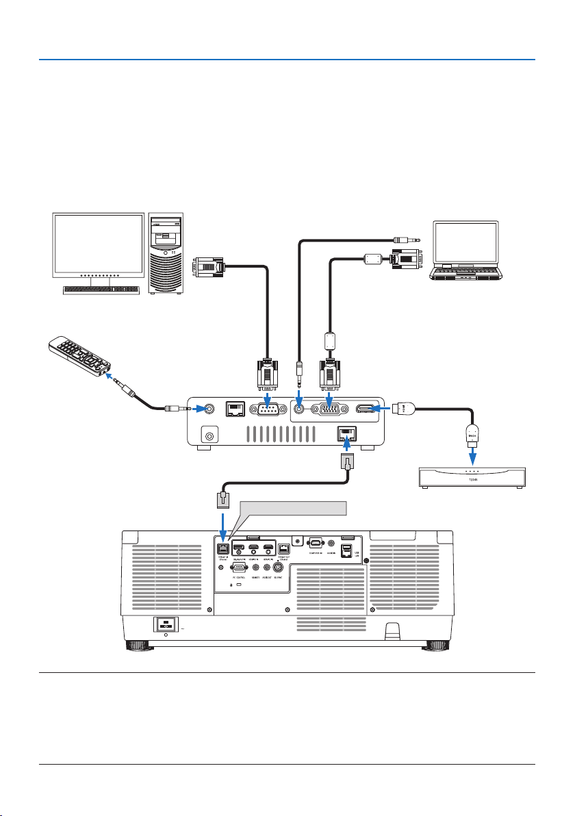
6. Connecting to Other Equipment
166
6-3. Connecting to a HDBaseT transmission device (sold commercially)
Use a LAN cable sold commercially to connect the HDBaseT IN/Ethernet port of the projector (RJ-45)
to a HDBaseT transmission device sold commercially.
The HDBaseT IN/Ethernet port of the projector supports HDMI signals (HDCP) from transmission
devices, control signals from external devices (serial, LAN) and remote control signals (IR commands).
• Refertotheowner’smanualaccompaniedwithyourHDBaseT transmission for connecting with
your external devices.
Connection example
RS-232C
AUDIO IN
COMPUTER IN
HDMI IN
LAN
WIRED REMOTE
DC IN
HDBaseT
HDBaseT IN/Ethernet
Computer (for control use)
Computer (for output use)
Example of a transmission device
Remote control
HDMI output video device
NOTE:
•Pleaseuseashieldedtwistedpair(STP)cableofCategory5eorhigherfortheLANcable(soldcommercially).
•ThemaximumtransmissiondistanceovertheLANcableis100m.
•Pleasedonotuseothertransmissionequipmentbetweentheprojectorandtransmissionequipment.Thepicturequalitymaybe
degradedasaresult.
•ThisprojectorisnotguaranteedtoworkwithallHDBaseTtransmissiondevicessoldcommercially.
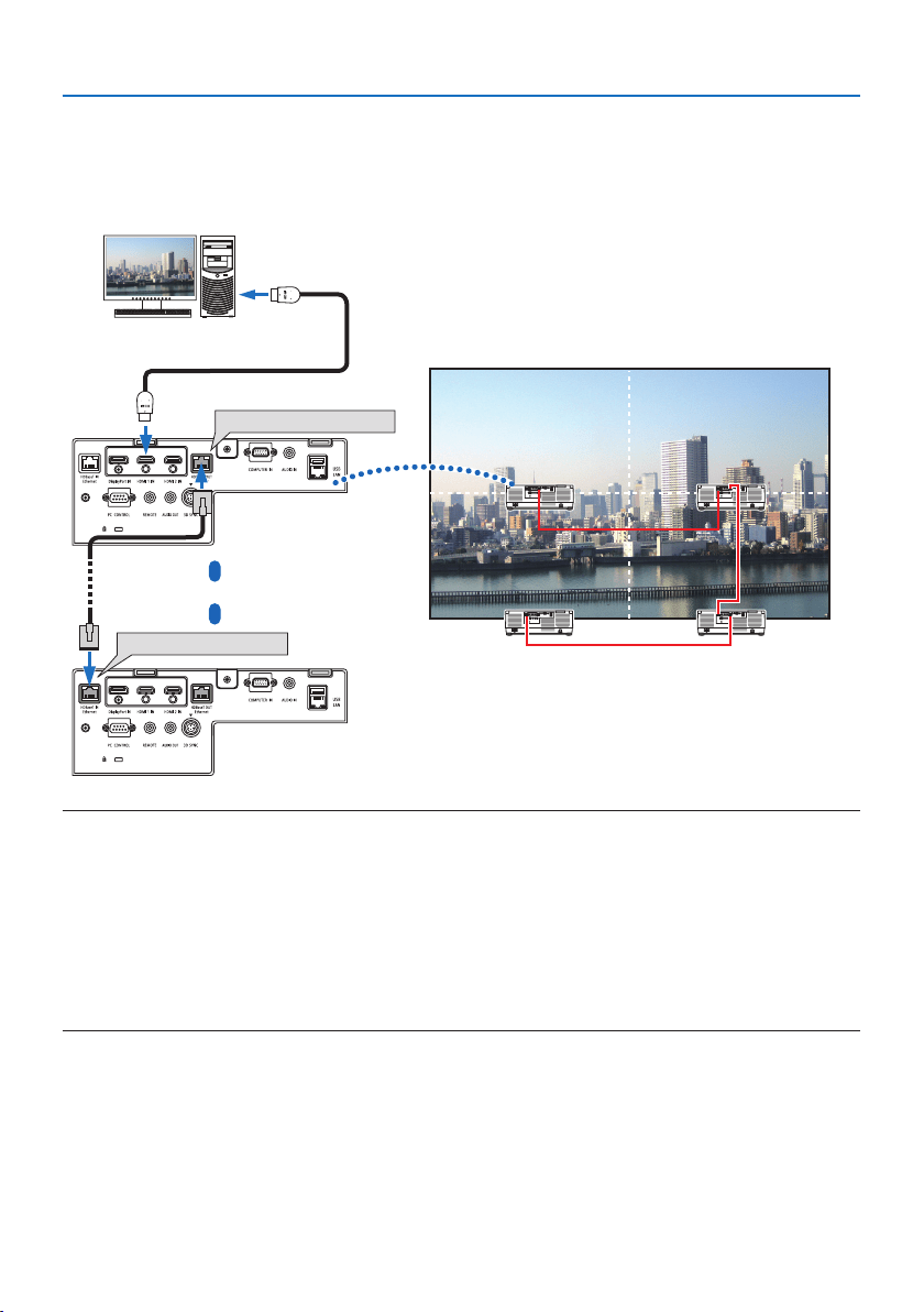
6. Connecting to Other Equipment
167
6-4. Connecting several projectors
It enables to project HDMI, DisplayPort, HDBaseT image on several projectors connecting the HD-
BaseT IN/Ethernet port and the HDBaseT OUT/Ethernet port by LAN cable. The projectors support
same brightness can be connected up to four units.
HDBaseT OUT/Ethernet
HDBaseT IN/Ethernet
Master projector
Other projector
NOTE:
•WhenoutputtingHDMIsignals,turnonthepowerofthevideodeviceontheoutputsideandkeepitconnectedbeforeinputting
videosignalsintothisdevice.TheHDBaseT OUT/Ethernetportoftheprojectorisequippedwithrepeaterfunction.Whenadevice
isconnectedtotheHDBaseT OUT/Ethernetport,theresolutionoftheoutputsignalislimitedbytheresolutionsupportedbythe
connecteddevice.
•ThesignalfromtheCOMPUTERIN terminal is not output from the HDBaseT OUT/Ethernetportofthisprojector.
•ConnectinganddisconnectinganLANcableorselectinganotherinputsourceonthesecondandsubsequentprojectorswilldisable
the HDBaseTrepeaterfunction.
•Thisprojectorisnotguaranteedtoworkcorrectlyintheconnectionwithanotherdeviceasamonitor.
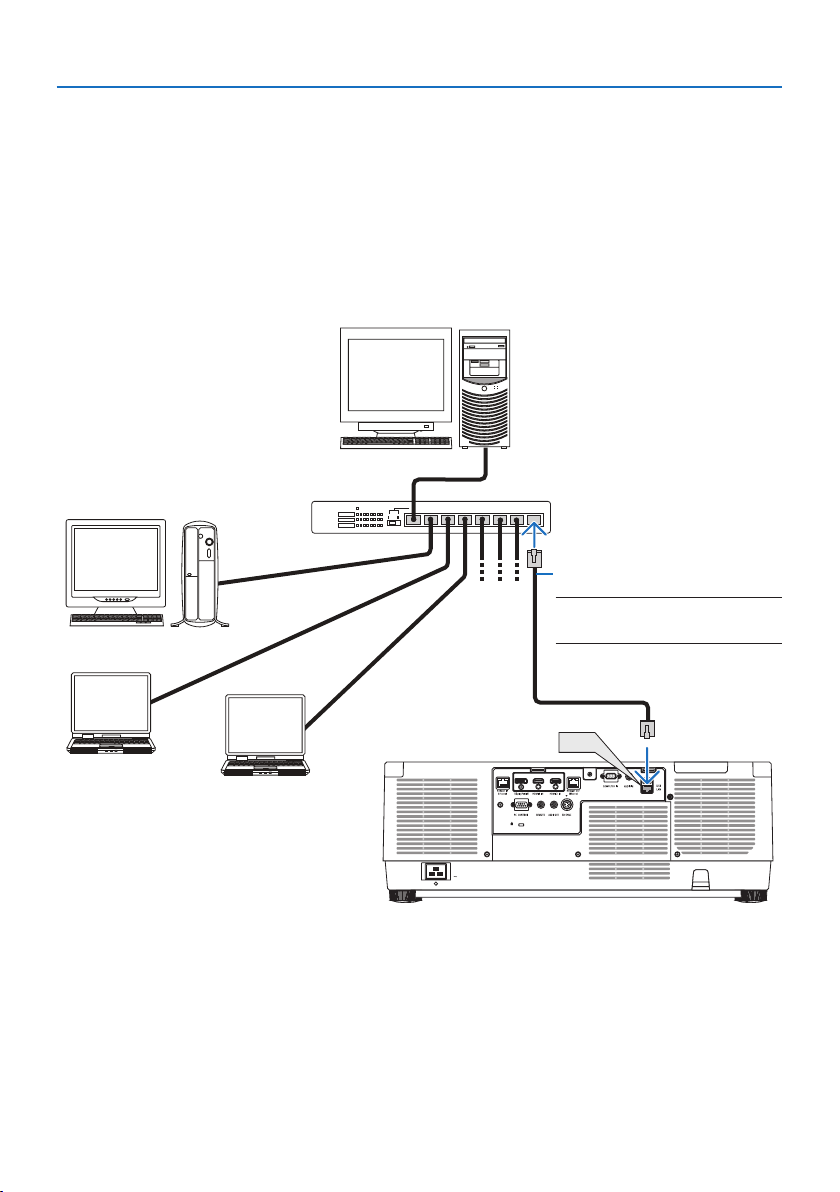
6. Connecting to Other Equipment
168
6-5. Connecting to a Wired LAN
The projector comes standard with a LAN port (RJ-45) which provides a LAN connection using a
LAN cable.
To use a LAN connection, you are required to set the LAN on the projector menu. Select [SETUP] →
[NETWORK SETTINGS] → [WIRED LAN]. (→ page
143).
Example of LAN connection
Example of wired LAN connection
LAN
Server
Hub
LAN cable (not supplied)
NOTE:
•UseaCategory5orhigherLANcable.
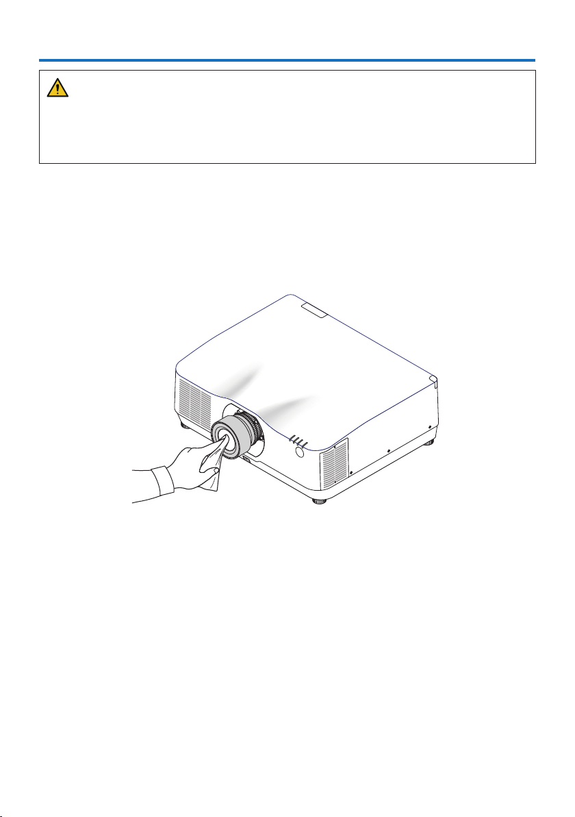
169
WARNING
•Turnotheprojector,andunplugtheprojectorbeforecleaning.
•Pleasedonotuseaspraycontainingammablegastoremovedustattachedtothelensand
cabinet. Doing so may result in fires.
7-1. Cleaning the Lens
•Turnotheprojectorbeforecleaning.
•Theprojectorhasaplasticlens.Useacommerciallyavailableplasticlenscleaner.
•Donotscratchormarthelenssurfaceasaplasticlensiseasilyscratched.
•Neverusealcoholorglasslenscleanerasdoingsowillcausedamagetotheplasticlenssurface.
7. Maintenance
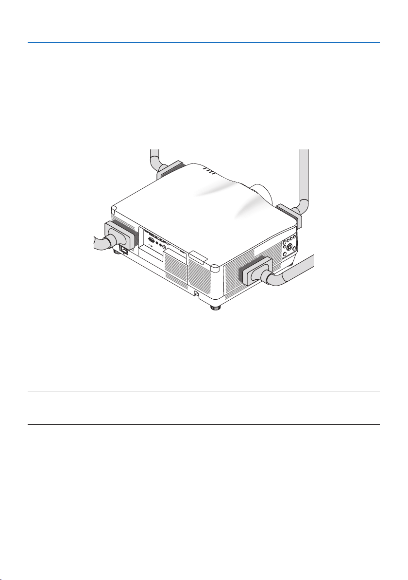
7. Maintenance
170
7-2. Cleaning the Cabinet
Turn off the projector, and unplug the projector before cleaning.
•Useadrysoftclothtowipedustothecabinet.
If heavily soiled, use a mild detergent.
•Neverusestrongdetergentsorsolventssuchasalcoholorthinner.
•Whencleaningtheventilationslitsorthespeakerusingavacuumcleaner,donotforcethe
brush of the vacuum cleaner into the slits of the cabinet.
Vacuum the dust off the ventilation slits.
•Cloggedventilationslitsmaycauseariseintheinternaltemperatureoftheprojector,resulting
in malfunction.
•Donotscratchorhitthecabinetwithyourngersoranyhardobjects
•Contactyourdealerforcleaningtheinsideoftheprojector.
NOTE:
•Donotapplyvolatileagentsuchasinsecticideonthecabinet,thelens,orthescreen.Donotleavearubberorvinylproductin
prolongedcontactwithit.Otherwisethesurfacenishwillbedeterioratedorthecoatingmaybestrippedo.

171
8-1. Throw distance and screen size
Three separate bayonet style lenses can be used on this projector. Refer to the information on this
page and use a lens suited for the installation environment (screen size and throw distance).
Lens types and throw distance
NP11FL/NP12ZL/NP13ZL/NP14ZL/NP15ZL/NP40ZL/NP41ZL/NP43ZL
(Unit:inch)
Screensize(inches)
Lensmodelname
NP11FLNP12ZLNP13ZLNP14ZLNP15ZLNP40ZLNP41ZLNP43ZL
30 — 28 – 37 36 – 74— — — — —
4026 38 – 50 48– 99 — — — — —
50 33 48– 6461 – 124— — 33 – 4654– 127 129 – 254
60 4059 – 77 74– 149146– 236 231 – 35440– 56 66 – 153 154– 303
80 53 79 – 103 99 – 200 196 – 317 310 – 47553 – 75 88 – 204204– 403
100 67 99 – 129 124– 250 246– 397 389 – 596 67 – 94110 – 256 254– 503
120 81 119 – 155 149– 300 296 – 477469– 716 81 – 113 133 – 307 303 – 602
150 101 149– 194187 – 376 372 – 598 588 – 897 101 – 142166 – 384378 – 752
200 — 199 – 259 250 – 502 497– 799 786 – 1199 135 – 190 223 – 513 502 – 1001
240— 239 – 312 301 – 602 598 – 959 945– 1440163 – 229 267 – 616 601 – 1201
300 — 300 – 390 377 – 754748– 1200 1183 – 1802 204– 286 335 – 770 750 – 1500
400— 400– 521 503 – 1005 1000 – 1602 1580 – 2406272 – 382 447– 1028 999 – 1998
500 — 501 – 651 629 – 1257 1251 – 20041977 – 3009 340– 478559 – 1285 1247– 2497
(Unit:m)
Screensize(inches)
Lensmodelname
NP11FLNP12ZLNP13ZLNP14ZLNP15ZLNP40ZLNP41ZLNP43ZL
30 — 0.7– 0.90.9– 1.9— — — — —
400.71.0– 1.31.2– 2.5— — — — —
50 0.81.2– 1.61.6– 3.1— — 0.8– 1.21.4– 3.23.3– 6.4
60 1.01.5– 1.91.9– 3.83.7– 6.05.9– 9.01.0– 1.41.7– 3.93.9– 7.7
80 1.42.0– 2.62.5– 5.15.0– 8.07.9– 12.11.4– 1.92.2– 5.25.2– 10.2
100 1.72.5– 3.33.2– 6.36.3– 10.19.9– 15.11.7– 2.42.8– 6.56.4– 12.8
120 2.13.0– 3.93.8– 7.67.5– 12.111.9– 18.22.0– 2.93.4– 7.87.7– 15.3
150 2.63.8– 4.94.8– 9.59.4– 15.214.9– 22.82.6– 3.64.2– 9.89.6– 19.1
200 — 5.1– 6.66.4– 12.712.6– 20.320.0– 30.53.4– 4.85.7– 13.012.7– 25.4
240— 6.1– 7.97.6– 15.315.2– 24.424.0– 36.64.1– 5.86.8– 15.615.3– 30.5
300 — 7.6– 9.99.6– 19.119.0– 30.530.1– 45.85.2– 7.38.5– 19.619.1– 38.1
400— 10.2– 13.212.8– 25.525.4– 40.740.1– 61.16.9– 9.711.4– 26.125.4– 50.8
500 — 12.7– 16.516.0– 31.931.8– 50.950.2– 76.48.6– 12.114.2– 32.631.7– 63.4
8. Appendix
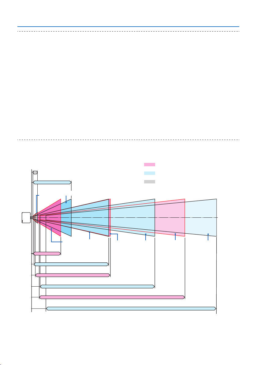
8. Appendix
172
TIP:
•Calculationofthethrowdistancefromthescreensize
NP11FLlensthrowdistance(inch/m)=H×0.8:27"/0.7m(min.)to101"/2.6m(max.)
NP12ZLlensthrowdistance(inch/m)=H×1.2toH×1.5:30"/0.7m(min.)to636"/16.1m(max.)
NP13ZLlensthrowdistance(inch/m)=H×1.5toH×3.0:38"/0.9m(min.)to1272"/32.3m(max.)
NP14ZLlensthrowdistance(inch/m)=H×2.9toH×4.7:147"/3.7m(min.)to1992"/50.6m(max.)
NP15ZLlensthrowdistance(inch/m)=H×4.6toH×7.1:234"/5.9m(min.)to3010"/76.4m(max.)
NP40ZLlensthrowdistance(inch/m)=H×0.8toH×1.1:33"/0.8m(min.)to466"/11.8m(max.)
NP41ZLlensthrowdistance(inch/m)=H×1.3toH×3.0:55"/1.4m(min.)to1272"/32.3m(max.)
NP43ZLlensthrowdistance(inch/m)=H×3.0toH×5.9:127"/3.2m(min.)to2501"/63.5m(max.)
“H”(Horizontal)referstothescreenwidth.
*Figuresdierbyseveral%withthetableabovebecausethecalculationisapproximate.
Ex.:Throwdistancewhenprojectingona150"screenusingtheNP41ZLlens:
Accordingtothe“ScreenSize(forreference)”table(→ page 174),H(screenwidth)=127"/323.1cm.
Thethrowdistanceis127"/323.1cm×1.3to127"/323.1cm×3.0=165"/420.0cmto381"/969.3cm(becauseofthezoom
lens).
Projectionrangeforthedierentlenses
NP40ZL:33"–478"/0.8–12.1m
NP11FL:26"–101"/0.7–2.6m
NP13ZL:36"–1257"/0.9–31.9m
NP41ZL:54"–1285"/1.4–32.6m
NP43ZL:129"–2497"/3.3–63.4m
NP15ZL:231"–3009"/5.9–76.4m
NP14ZL:146"–2004"/3.7–50.9m
NP12ZL:28"–651"/0.7–16.5m
Motorizedzoom,Motorizedfocus
Manualzoom,Manualfocus
Manual focus
40"–150"
30"–500"
50"–500"
60"–500"50"–500"60"–500"
30"–500"
50"–500"
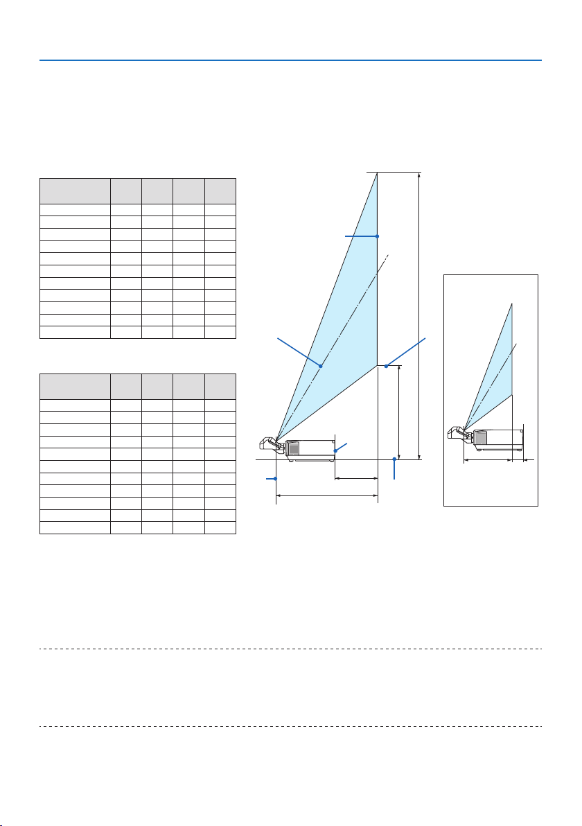
8. Appendix
173
NP44ML
•Throwdistanceshowsadistancebetweenthecenterofthelensunitprojectionwindowandthe
screen face.
•Ifthereisawallbelowthescreenbottom,allow0.2m/8"orlongerofL1distancetoinstallthe
projector.
(Unit:inch)
Screensize
(inches)
L1 L2 H1 H2
80 -2 22 21 63
100 3 27 25 78
120 9 33 28 92
150 18 4234114
180 26 50 40135
200 32 56 43149
2404468 51 178
270 52 76 56 199
300 61 85 62 221
350 75 99 71 257
40090 11480 292
(Unit:m)
Screensize
(inches)
L1 L2 H1 H2
80 -0.060.550.531.61
100 0.080.700.631.98
120 0.230.840.722.34
150 0.451.060.862.88
180 0.671.281.013.43
200 0.811.431.103.79
2401.111.721.294.52
270 1.331.941.435.07
300 1.542.161.575.61
350 1.912.521.816.65
4002.282.892.047.43
L2
H2
H1
L1
①
②
③
⑤
⑦
⑧
⑥
④
L2 L1
① Screen top end
② Screen face
③ Screen center
④ Screen bottom
⑤ Center of the lens unit projection
window
⑥ Projector rear face
⑦ Throw distance
⑧ Projector bottom face
(when L1 is minus)
TIP:
•Calculationofthethrowdistancefromthescreensize
NP44MLlensthrowdistance(m)=H×0.32:22"/0.6m(min.)to109"/2.8m(max.)
“H”(Horizontal)referstothescreenwidth.
*Figuresdierbyseveral%withthetableabovebecausethecalculationisapproximate.
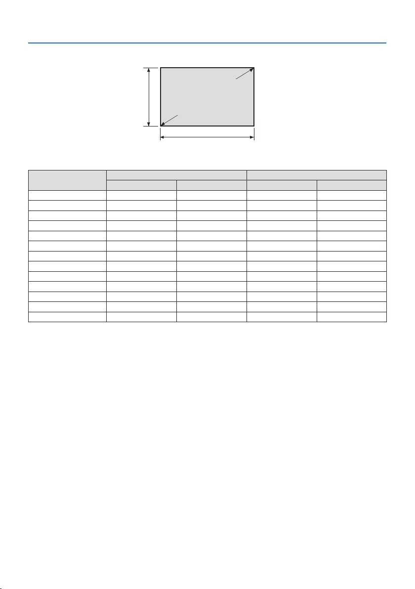
8. Appendix
174
Tables of screen sizes and dimensions
Screen height
Screen width
16:10screensize
(diagonal)
Size (inches)
Screen width Screen height
(inches) (cm) (inches) (cm)
30 25.4 64.6 15.9 40.4
40 33.9 86.2 21.2 53.8
50 42.4 107.7 26.5 67.3
60 50.9 129.2 31.8 80.8
80 67.8 172.3 42.4 107.7
100 84.8 215.4 53.0 134.6
120 101.8 258.5 63.6 161.5
150 127.2 323.1 79.5 201.9
200 169.6 430.8 106.0 269.2
240 203.5 516.9 127.2 323.1
300 254.4 646.2 159.0 403.9
400 339.2 861.6 212.0 538.5
500 424.0 1077.0 265.0 673.1
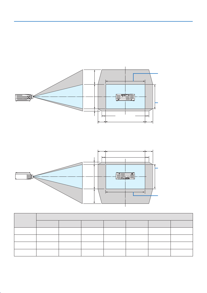
8. Appendix
175
Lens shifting range
This projector is equipped with a lens shift function for adjusting the position of the projected im-
age by buttons. The lens can be shifted within the range shown below.
Descriptionofsymbols:Vindicatesvertical(heightoftheprojectedimage),Hindicateshorizontal
(width of the projected image).
Desk/front projection
Height of projected
image
Width of projected
image
③ ④
①
②
100%V
10%H10%H
100%H
Ceiling/front projector
Height of projected
image
Width of projected
image
③ ④
①
②
100%V
10%H10%H
100%H
Number in
the figure
Lens Unit
NP12ZL NP13ZL NP14ZL NP15ZL NP40ZL NP41ZL NP43ZL
①
50%V 50%V 50%V 50%V 50%V 50%V 50%V
②
10%V 10%V 10%V 10%V 10%V 10%V 10%V
③
30%H 30%H * 30%H 30%H 20%H 20%H 20%H
④
30%H 30%H * 30%H 30%H 20%H 20%H 20%H
* The maximum adjustable range for lens shift (H) is 15%H when the NP13ZL lens is used on 150" or larger
screen.

8. Appendix
176
Example:Whenprojectingona150"screenusingtheNP40ZLlens:
According to the “Tables of screen sizes and dimensions” (→ page
174), H (screen width) = 323.1
cm and V (screen height) = 201.9 cm
Adjustmentrangeintheverticaldirection:Theprojectedimagecanbemovedupward0.50×
201.9cm≈111cmanddownward0.1×201.9cm≈20cm(whenthelensisatthecenterposition).
Adjustmentrangeinthehorizontaldirection:Theprojectedimagecanbemovedtotheleft0.20×
323.1 cm ≈ 65 cm, and this applies to the right direction which means approx. 65 cm.
* Your calculated figure has a few percent margin of error because the calculation formula is approximate.
NOTE:
•UseNP11FLatthehomeposition.Ifnecessary,ne-adjustthepositionoftheprojectedimageusingthelensshiftfunction.
•TheNP44MLmustbexedtotheprojectorusingtheseparatelysoldsupportkit(NP02LK).Loosenthescrewsofthesupportbracket,
youcanne-adjustmentofthelensshift.

8. Appendix
177
8-2. Compatible Input Signal List
HDMI/HDBaseT
Signal Resolution ( dots ) Aspect Ratio Refresh Rate ( Hz )
VGA 640 ×480 4 :3 60/72/75/85/iMac
SVGA 800 ×600 4 :3 56/60/72/75/85/iMac
XGA 1024 ×768 4 :3 60/70/75/85/iMac
HD 1280 ×720 16 :9 60
WXGA 1280 ×768 15 :9 60
1280 ×800 16 :10 60
Quad-VGA 1280 ×960 4 :3 60
SXGA 1280 ×1024 5 :4 60
FWXGA 1360 ×768 16 :9 60
1366 ×768 16 :9 60
SXGA+ 1400 ×1050 4 :3 60
WXGA+ 1440 ×900 16 :10 60
WXGA++ 1600 ×900 16 :9 60
WSXGA+ 1680 ×1050 16 :10 60
UXGA 1600 ×1200 *
1
4 :3 60
Full HD 1920 ×1080 *
1
16 :9 60
WUXGA 1920 ×1200 *
1
16 :10 60 (Reduced Blanking)
2K 2048 ×1080 17 :9 60
WQHD
iMac 27"
2560 ×1440 16 :9 60
WQXGA 2560 ×1600 16 :10 60 (Reduced Blanking)
4K 3840 ×2160 16 :9 24/25/30/50*
2
/60*
2
4096 ×2160 17 :9 24/25/30/50*
2
/60*
2
HDTV (1080p) 1920 ×1080 *
1
16 :9 24/25/30/50*
2
/60*
2
HDTV (1080i) 1920 ×1080 *
1
16 :9 48/50/60
HDTV (720p) 1280 ×720 16 :9 50/60
SDTV (480p) 720/1440 ×480 4:3/16:960
SDTV (576p) 720/1440 ×576 4:3/16:950
SDTV (480i) 1440 ×480 4:3/16:960
SDTV (576i) 1440 ×576 4:3/16:950

8. Appendix
178
DisplayPort
Signal Resolution ( dots ) Aspect Ratio Refresh Rate ( Hz )
VGA 640 ×480 4 :3 60
SVGA 800 ×600 4 :3 60
XGA 1024 ×768 4 :3 60
HD 1280 ×720 16 :9 60
WXGA 1280 ×768 15 :9 60
1280 ×800 16 :10 60
Quad-VGA 1280 ×960 4 :3 60
SXGA 1280 ×1024 5 :4 60
FWXGA 1360 ×768 16 :9 60
1366 ×768 16 :9 60
SXGA+ 1400 ×1050 4 :3 60
WXGA+ 1440 ×900 16 :10 60
WXGA++ 1600 ×900 16 :9 60
WSXGA+ 1680 ×1050 16 :10 60
UXGA 1600 ×1200 *
1
4 :3 60
Full HD 1920 ×1080 *
1
16 :9 60
WUXGA 1920 ×1200 *
1
16 :10 60 (Reduced Blanking)
2K 2048 ×1080 17 :9 60
WQHD
iMac 27"
2560 ×1440 16 :9 60
WQXGA 2560 ×1600 16 :10 60 (Reduced Blanking)
4K 3840 ×2160 16 :9 24/25/30/50/60
4096 ×2160 17 :9 24/25/30/50/60
HDTV (1080p) 1920 ×1080 16 :9 24/25/30/50/60
HDTV (720p) 1280 ×720 16 :9 50/60
SDTV (480i/p) 720/1440 ×480 4:3/16:960
SDTV (576i/p) 720/1440 ×576 4:3/16:950

8. Appendix
179
Analog RGB
Signal Resolution ( dots ) Aspect Ratio Refresh Rate ( Hz )
VGA 640 ×480 4 :3 60/72/75/85/iMac
SVGA 800 ×600 4 :3 56/60/72/75/85/iMac
XGA 1024 ×768 4 :3 60/70/75/85/iMac
XGA+ 1152 ×864 4 :3 75
HD 1280 ×720 16 :9 60
WXGA 1280 ×768 15 :9 60/75/85
1280 ×800 16 :10 60/75/85
Quad-VGA 1280 ×960 4 :3 60/85
SXGA 1280 ×1024 5 :4 60/75/85
FWXGA 1360 ×768 16 :9 60
1366 ×768 16 :9 60
SXGA+ 1400 ×1050 4 :3 60/75
WXGA+ 1440 ×900 16 :10 60/75/85
WXGA++ 1600 ×900 16 :9 60
UXGA 1600 ×1200 *
1
4 :3 60
WSXGA+ 1680 ×1050 16 :10 60
Fill HD 1920 ×1080 *
1
16 :9 60
WUXGA 1920 ×1200 *
1
16 :10 60 (Reduced Blanking)
2K 2048 ×1080 17 :9 60
Full HD 1920 ×1080 *
1
16 :9 60
MAC 13" 640 ×480 4 :3 67
MAC 16" 832 ×624 4 :3 75
MAC 19" 1024 ×768 4 :3 75
MAC 21" 1152 ×870 4 :3 75
MAC 23" 1280 ×1024 5 :4 65
Analog Component
Signal Resolution ( dots ) Aspect Ratio Refresh Rate ( Hz )
HDTV (1080p) 1920 ×1080 16 :9 50/60
HDTV (1080i) 1920 ×1080 16 :9 48/50/60
HDTV (720p) 1280 ×720 16 :9 50/60
SDTV (480p) 720 ×480 4:3/16:960
SDTV (576p) 720 ×576 4:3/16:950
SDTV (480i) 720 ×480 4:3/16:960
SDTV (576i) 720 ×576 4:3/16:950

8. Appendix
180
HDMI/HDBaseT 3D
Signal Resolution ( dots ) Aspect Ratio Refresh Rate ( Hz ) 3D Format
1920 ×1080p 16 :9 23.98/24 Frame Packing
Side By Side (Half)
Top And Bottom
25 Side By Side (Half)
Top And Bottom
29.97/30 Frame Packing
Side By Side (Half)
Top And Bottom
50 Side By Side (Half)
Top And Bottom
59.94/60 Side By Side (Half )
Top And Bottom
1920 ×1080i 50 Side By Side (Half)
Top And Bottom
59.94/60 Side By Side (Half )
Top And Bottom
1280 ×720p 23.98/24 Frame Packing
Side By Side (Half)
Top And Bottom
25 Side By Side (Half)
Top And Bottom
29.97/30 Frame Packing
Side By Side (Half)
Top And Bottom
50 Frame Packing
Side By Side (Half)
Top And Bottom
59.94/60 Frame Packing
Side By Side (Half)
Top And Bottom
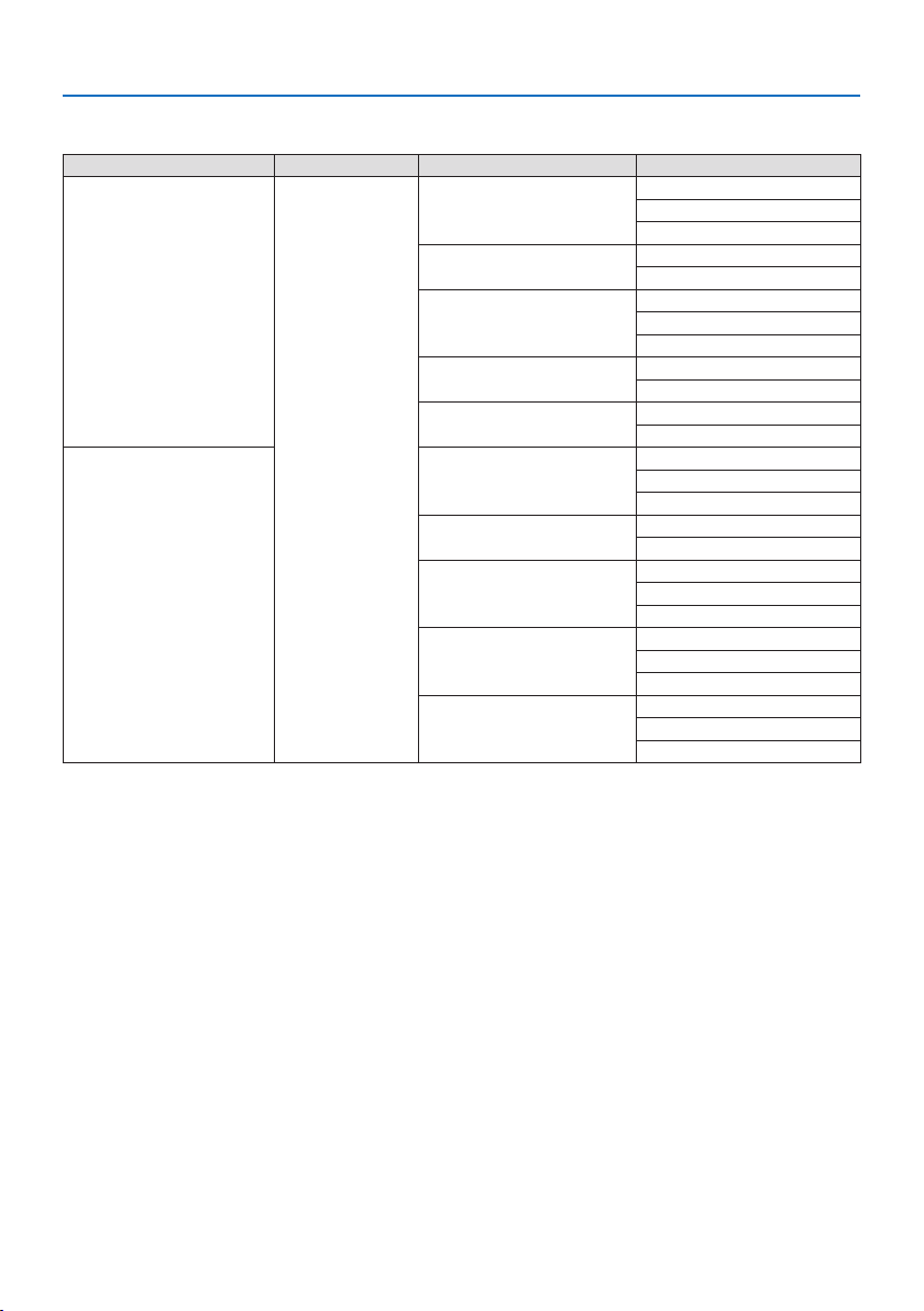
8. Appendix
181
DisplayPort 3D
Signal Resolution ( dots ) Aspect Ratio Refresh Rate ( Hz ) 3D Format
1920 ×1080p 16 :9 23.98/24 Frame Packing
Side By Side (Half)
Top And Bottom
25 Side By Side (Half)
Top And Bottom
29.97/30 Frame Packing
Side By Side (Half)
Top And Bottom
50 Side By Side (Half)
Top And Bottom
59.94/60 Side By Side (Half )
Top And Bottom
1280 ×720p 23.98/24 Frame Packing
Side By Side (Half)
Top And Bottom
25 Side By Side (Half)
Top And Bottom
29.97/30 Frame Packing
Side By Side (Half)
Top And Bottom
50 Frame Packing
Side By Side (Half)
Top And Bottom
59.94/60 Frame Packing
Side By Side (Half)
Top And Bottom
*1 Native resolution
*2 HDBaseT does not support this signal.
•Signalsexceedingtheprojector’sresolutionarehandledwithAdvancedAccuBlend.
•WithAdvancedAccuBlend,thesizeofcharactersandruledlinesmaybeunevenandcolorsmaybeblurred.
•Uponshipment,theprojectorissetforsignalswithstandarddisplayresolutionsandfrequencies,butadjust-
ments may be required depending on the type of computer.
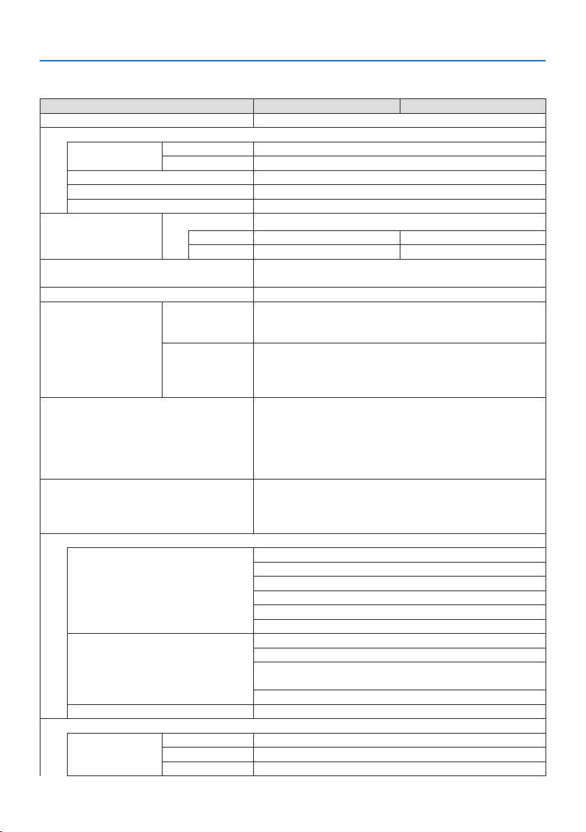
8. Appendix
182
8-3. Specifications
Model name PA1004UL-W/PA1004UL-B PA804UL-W/PA804UL-B
Method Three primary color liquid crystal shutter projection method
Specifications of main parts
Liquid crystal
panel
Size 0.76"(withMLA)×3(aspectratio:16:10)
Pixels
(*1)
2,304,000(1920dots×1200lines)
Projection lenses Refer to the specifications of option lens (→ 185 page)
Light source Laser diode
Optical device Integrator, Dichroic Mirror, XDP
Light output
(*2)
(*3)
REF. LIGHT MODE
NORMAL 9000 lm 7500 lm
BOOST 10000 lm 8200 lm
Screen size (throw distance) Please refer to the "Throw distance and screen size" (→
171
page)
Color reproducibility 10-bit color processing (approx. 1.07 billion colors)
Scanning frequency Horizontal Analog:15kHz,24to100kHz(24kHzorgreaterforRGB
inputs), conforming to VESA standards
Digital:15kHz,24to153kHz,conformingtoVESAstandards
Vertical Analog:48Hz,50to85Hz,100,120HzconformingtoVESA
standards
Digital:24,25,30,48Hz,50to85Hz,100,120Hzconforming
to VESA standards
Main adjustment functions Zoom, Focus, Lens Shift (Refer to the specifications of option
lens → page
185), input signal switching (HDMI1/HDMI2/
DisplayPort/COMPUTER/HDBaseT), auto image adjustment,
picture enlarging, picture position adjustment, muting (both
video and audio), power on/standby, on-screen display/selec-
tion, etc.
Max.displayresolution(horizontal×verti-
cal)
AnalogWUXGA(1920×1200)withAdvancedAccuBlendPixel
clockfrequency:lessthan165MHz
DigitalQuadHD(4096×2160)withAdvancedAccuBlend
Pixelclockfrequency:lessthan600MHz(HDBaseT:300MHz)
Input signals
R,G,B,H,V RGB:0.7Vp-p/75Ω
Y:1.0Vp-p/75Ω(withNegativePolaritySync)
Cb,Cr(Pb,Pr):0.7Vp-p/75Ω
H/VSync:4.0Vp-p/TTL
CompositeSync:4.0Vp-p/TTL
SynconG:1.0Vp-p/75Ω(withSync)
Component Y:1.0Vp-p/75Ω(withSync)
Cb,Cr(Pb,Pr):0.7Vp-p/75Ω
DTV:480i,480p,720p,1080i,1080p(60Hz)
576i, 576p, 720p, 1080i (50 Hz)
DVD:Progressivesignal(50/60Hz)
Audio 0.5Vrms/22kΩorgreater
Input/output connectors
Computer/Com-
ponent
Video input MiniD-Sub15-pin×1
Audio input Stereominijack×1
Audio output Stereominijack×1(commonforallsignals)

8. Appendix
183
Model name PA1004UL-W/PA1004UL-B PA804UL-W/PA804UL-B
HDMI Video input HDMI®ConnectortypeA×2
RJ-450×1,100BASE-TXcompatible
DeepColor(colordepth):8-/10-/12-bitcompatible
Colorimetry:RGB,YCbCr444,YCbCr422,YCbCr420,REC2020,
REC709, REC601
Supports LipSync, HDCP
(*4)
, 4K HDR and 3D
Audio input HDMI:Samplingfrequency–32/44.1/48kHz,Samplingbits–
16/20/24 bits
HDBaseT/Ethernet Video input DeepColor(colordepth):Support8/10/12bits
Colorimetry:SupportRGB,YCbCr444,YCbCr422,YCbCr420,
REC2020, REC709, REC601
Support LipSync , HDCP
(*4)
, 3D, HDR
Video output RJ-45×1,100BASE-TX
DeepColor(colordepth):Support8/10/12bits
Colorimetry:SupportRGB,YCbCr444,YCbCr422,REC709,
REC601
Support LipSync, HDCP
(*4)
, 3D
Audio input Samplingfrequency:32/44.1/48kHz
Samplingbit:16/20/24bit
Audio output Samplingfrequency:32/44.1/48kHz
Samplingbit:16/20/24bits
DisplayPort Video input DisplayPort×1
Datarate:5.4Gbps/2.7Gbps/1.62Gbps
No.lanes:1lane/2lanes/4lanes
Colordepth:8bits,10bits,12bits
Colorimetry:RGB,YCbCr444,YCbCr422,REC709, REC601
HDCP compatible
(*4)
Audio input DisplayPort:Samplingfrequency–32/44.1/48kHz,Sampling
bits–16/20/24bits
PC control terminal D-Sub9-pin×1
USB port USBtypeA×1
Ethernet/LAN/HDBaseT port RJ-45×1,Supports10BASE-T/100BASE-TX
Remote terminal Stereominijack×1
3D SYNC output terminal 5 V / 10 mA, synchronized signal output for 3D use
Usage environment
(*5)
Operatingtemperature:41to104°F(5to40°C)
Operatinghumidity:20to80%(withnocondensation)
Storagetemperature:14to122°F(−10to50°C)
Storagehumidity:20to80%(withnocondensation)
Operatingaltitude:0to3650m/12000feet
(1700to3650m/5500to12000feet:Set[FAN MODE] to [HIGH
ALTITUDE])
Power supply 100-240 V AC, 50/60 Hz

8. Appendix
184
Model name PA1004UL-W/PA1004UL-B PA804UL-W/PA804UL-B
Power con-
sumption
REF. LIGHT
MODE
BOOST 845 W (100-130 V AC)
810 W (200-240 V AC)
675 W (100-130 V AC)
655 W (200-240 V AC)
NORMAL 750 W (100-130 V AC)
725 W (200-240 V AC)
635 W (100-130 V AC)
615 W (200-240 V AC)
ECO1 610 W (100-130 V AC)
590 W (200-240 V AC)
515 W (100-130 V AC)
505 W (200-240 V AC)
ECO2 405 W (100-130 V AC)
395 W (200-240 V AC)
360 W (100-130 V AC)
350 W (200-240 V AC)
STANDBY Network 0.8 W (100-130 V AC) / 0.8 W (200-240 V AC)
Normal 0.22 W (100-130 V AC) / 0.28 W (200-240 V AC)
Rated input current 10.5 A (100-130 V AC)
4.6 A (200-240 V AC)
8.6 A (100-130 V AC)
3.8 A (200-240 V AC)
Power cord specification 15 A or higher
Externaldimensions(W×H×D)23.6"(width)×8.2"(height)×19.3"(depth)/
599(width)×208(height)×490(depth)mm
(not including protruding parts)
23.6"(width)×8.5"(height)×19.3"(depth)/
599(width)×216(height)×490(depth)mm
(including protruding parts)
Weight 53.8 lbs/24.4 kg
(not including lens)
53.1 lbs/24.1 kg
(not including lens)
*1 Effective pixels are more than 99.99%.
*2 This is the light output value (lumens) mounting the lens unit, NP41ZL, when the [PRESET] mode is set to
[HIGH-BRIGHT]. The light output values will be dropped according to the setting of [REF. LIGHT MODE]. If
any other mode is selected as the [PRESET] mode, the light output value may drop slightly.
*3 Compliance with ISO21118-2012
*4 If you are unable to view material via the HDMI input, this does not necessarily mean the projector is not
functioning properly. With the implementation of HDCP, there may be cases in which certain content is
protected with HDCP and might not be displayed due to the decision/intention of the HDCP community
(Digital Content Protection, LLC).
Video:HDR,DeepColor,8/10/12-bit,LipSync.
Audio:LPCM;upto2ch,samplerate32/44.1/48KHz,samplebit;16/20/24-bit
HDMI:SupportsHDCP 2.2/1.4
DisplayPort:SupportsHDCP1.3
HDBaseT:SupportsHDCP 2.2/1.4
*5 “Forced ECO Mode” is set depending on the temperature of the operating environment and [REF. LIGHT
MODE] setting, the projector goes into “Forced ECO Mode”. (→ page
43)
•Thesespecicationsandtheproduct’sdesignaresubjecttochangewithoutnotice.

8. Appendix
185
Option lens (sold separately)
NP11FL Manual focus
(Throwratio0.81:1,F2.3,f=13.2mm)
NP12ZL Motorized lens shift, Manual zoom, Manual focus
(Throwratio1.16–1.52:1,F2.20–2.69,f=19.4–25.3mm)
NP13ZL Motorized lens shift, Manual zoom, Manual focus
(Throwratio1.46–2.95:1,F1.70–2.37,f=24.4–48.6mm)
NP14ZL Motorized lens shift, Manual zoom, Manual focus
(Throwratio2.90–4.68:1,F2.20–2.64,f=48.5–77.6mm)
NP15ZL Motorized lens shift, Manual zoom, Manual focus
(Throwratio4.59–7.02:1,F2.20–2.70,f=76.6–116.5mm)
NP40ZL Motorized lens shift, Motorized zoom , Motorized focus
(Throwratio0.79–1.11:1,F2.0–2.5,f=13.3–18.6mm)
NP41ZL Motorized lens shift, Motorized zoom , Motorized focus
(Throwratio1.30–3.02:1,F1.7–2.0,f=21.8–49.8mm)
NP43ZL Motorized lens shift, Motorized zoom, Motorized focus
(Throwratio2.99–5.93:1,F2.2–2.6,f=49.7–99.8mm)
NP44ML Motorized lens shift, Motorized focus
(Throwratio0.32:1,F2.0,f=6.27mm)
NOTE:
•Theabovethrowratioisforprojectingon100"screen.
•UseNP11FLatthehomeposition.Ifnecessary,ne-adjustthepositionoftheprojectedimageusingthelensshiftfunction.
•FixtheNP44MLtotheprojectorusingtheseparatelysoldsupportkit(NP02LK).Loosenthescrewsofthesupportbracket,youcan
ne-adjustmentofthelensshift.
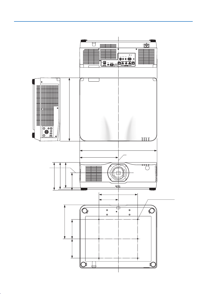
8. Appendix
186
216 (8.5)
262 (10.3)
150 (5.9)
150 (5.9)
134 (5.3)
599 (23.6)
300 (11.8)
150 (5.9)
6-M4
299.5 (11.8)
490 (19.3)
197 (7.8)
208 (8.2)
8-4. Cabinet Dimensions
Unit:mm(inch)
Lens center
Lens center
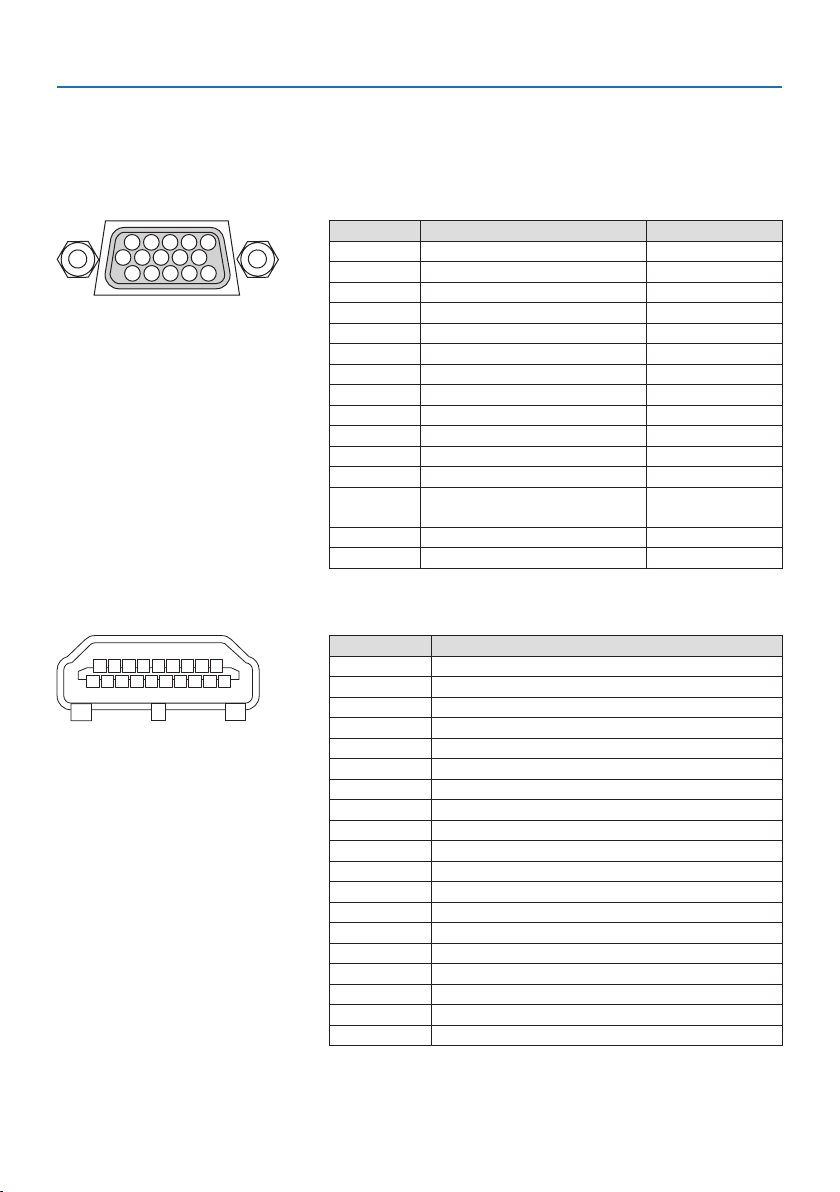
8. Appendix
187
8-5. Pin assignments and signal names of main connectors
COMPUTER IN/ Component Input Connector (Mini D-Sub 15 Pin)
Connection and signal level of each pin
51423
10
11 12 13 14 15
6978
Signal Level
Videosignal:0.7Vp-p(Analog)
Syncsignal:TTLlevel
Pin No. RGB Signal (Analog) YCbCr Signal
1 Red Cr
2 Green or Sync on Green Y
3 Blue Cb
4 Ground
5 Ground
6 Red Ground Cr Ground
7 Green Ground Y Ground
8 Blue Ground Cb Ground
9 No Connection
10 Sync Signal Ground
11 No Connection
12 Bi-directional DATA (SDA)
13 Horizontal Sync or Composite
Sync
14 Vertical Sync
15 Data Clock
HDMI 1 IN/HDMI 2 IN Connector (Type A)
135791113151719
2 46810 12 14 16 18
Pin No. Signal
1 TMDS Data 2+
2 TMDS Data 2 Shield
3 TMDS Data 2−
4 TMDS Data 1+
5 TMDS Data 1 Shield
6 TMDS Data 1−
7 TMDS Data 0+
8 TMDS Data 0 Shield
9 TMDS Data 0−
10 TMDS Clock +
11 TMDS Clock Shield
12 TMDS Clock−
13 CEC
14 Disconnection
15 SCL
16 SDA
17 DDC/CEC grounding
18 +5 V power supply
19 Hot plug detection
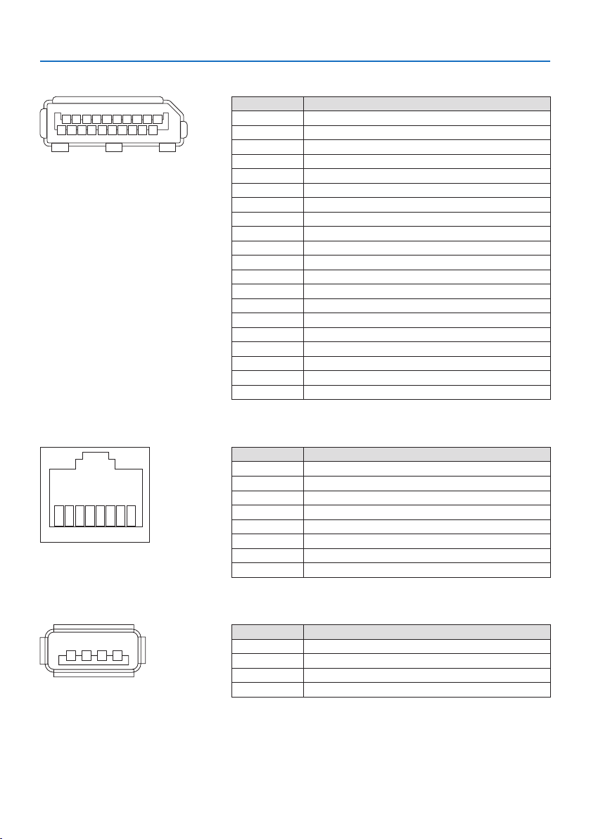
8. Appendix
188
DisplayPort IN Connector
135791113151719
246810 12 14 16 18 20
Pin No. Signal
1 Main link lane 3−
2 Grounding 3
3 Main link lane 3+
4 Main link lane 2−
5 Grounding 2
6 Main link lane 2+
7 Main link lane 1−
8 Grounding 1
9 Main link lane 1+
10 Main link lane 0−
11 Grounding 0
12 Main link lane 0+
13 Configuration 1
14 Configuration 2
15 Supplementary channel +
16 Grounding 4
17 Supplementary channel −
18 Hot plug detection
19 Return
20 +3.3 V power supply
HDBaseT IN/Ethernet Port (RJ-45)
12345678
Pin No. Signal
1 TxD+/HDBT0+
2 TxD−/HDBT0−
3 RxD+/HDBT1+
4 Disconnection/HDBT2+
5 Disconnection/HDBT2−
6 RxD−/HDBT1−
7 Disconnection/HDBT3+
8 Disconnection/HDBT3−
USB Port (Type A)
1
3
24
Pin No. Signal
1 V
BUS
2 D−
3 D+
4 Grounding

8. Appendix
189
PC CONTROL Port (D-Sub 9 Pin)
12345
6789
Pin No. Signal
1 Unused
2 RxD reception data
3 TxD transmission data
4 Unused
5 Grounding
6 Unused
7 RTS transmission request
8 CTS transmission allowed
9 Unused
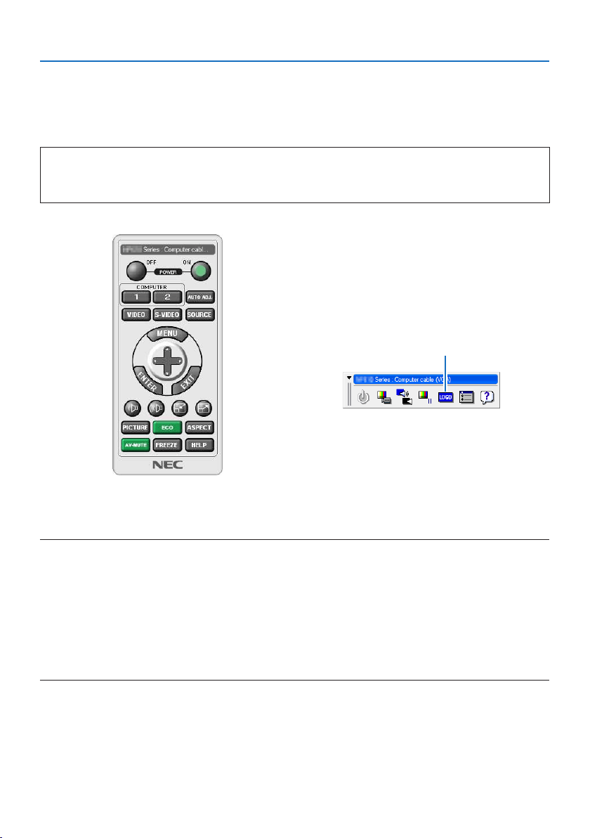
8. Appendix
190
8-6. Changing the Background Logo (Virtual Remote Tool)
This will help you perform operations such as projector’s power on or off and signal selection via a
LAN connection. It is also used to send an image to the projector and register it as the logo data of
the projector. After registering it, you can lock the logo to prevent it from changing.
Control Functions
Power On/Off, signal selection, picture freeze, picture mute, audio mute, Logo transfer to the
projector, and remote control operation on your PC.
Virtual Remote screen
Use this button for changing the
background logo.
Remote Control Window Toolbar
For getting the Virtual Remote Tool,pleasevisitourwebsiteanddownloadit:
https://www.nec-display.com/dl/en/index.html
NOTE:
•RemoteControlWindowisnotavailableforchangingthebackgroundlogo.
PleaseseetheHELPmenuoftheVirtual Remote ToolabouthowtodisplaytheToolbar.
•Logodata(graphics)thatcanbesenttotheprojectorwithVirtual Remote Tool has the following restrictions:
(OnlyviaserialorLANconnection)
*Filesize:Within256kilobytes
*Imagesize:Withintheresolutionoftheprojector
*Fileformat:PNG(Fullcolor)
•Logodata(image)sentusingtheVirtual Remote Toolwillbedisplayedinthecenterwiththesurroundingareainblack.
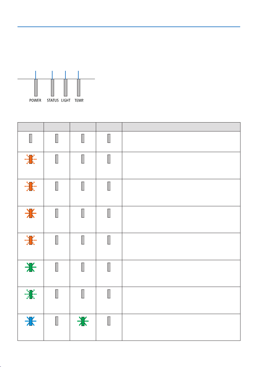
8. Appendix
191
8-7. Troubleshooting
This section helps you resolve problems you may encounter while setting up or using the projector.
Feature of each indicator
① ② ③ ④
① POWER indicator
② STATUS indicator
③ LIGHT indicator
④ TEMP. indicator
Indicator Message (Status message)
POWER STATUS LIGHT TEMP. Projector status
Power is off
OOOO
In the state of Standby ([POWER-SAVING] is [ON] and
the network is ready.
Orange
(Blink*
1
)
OOO
In the state of Standby ([POWER-SAVING] is [ON] and
the network is unavailable.
Orange
(Blink*
2
)
OOO
In the state of Standby ([POWER-SAVING] is [ON] and
the network is available)
Orange
(Light)
OOO
[ON] time as the [PROGRAM TIMER] is activated. (In the
state of Standby)
Orange
(Blink*
3
)
OOO
In the state of Sleep
Green
(Light)
OOO
[ON] time as the [PROGRAM TIMER] is activated. (In the
state of Sleep)
Green
(Blink*
3
)
OOO
Powered state ([REF. LIGHT MODE] is [NORMAL])
Blue
(Light)
OGreen
(Light)
O
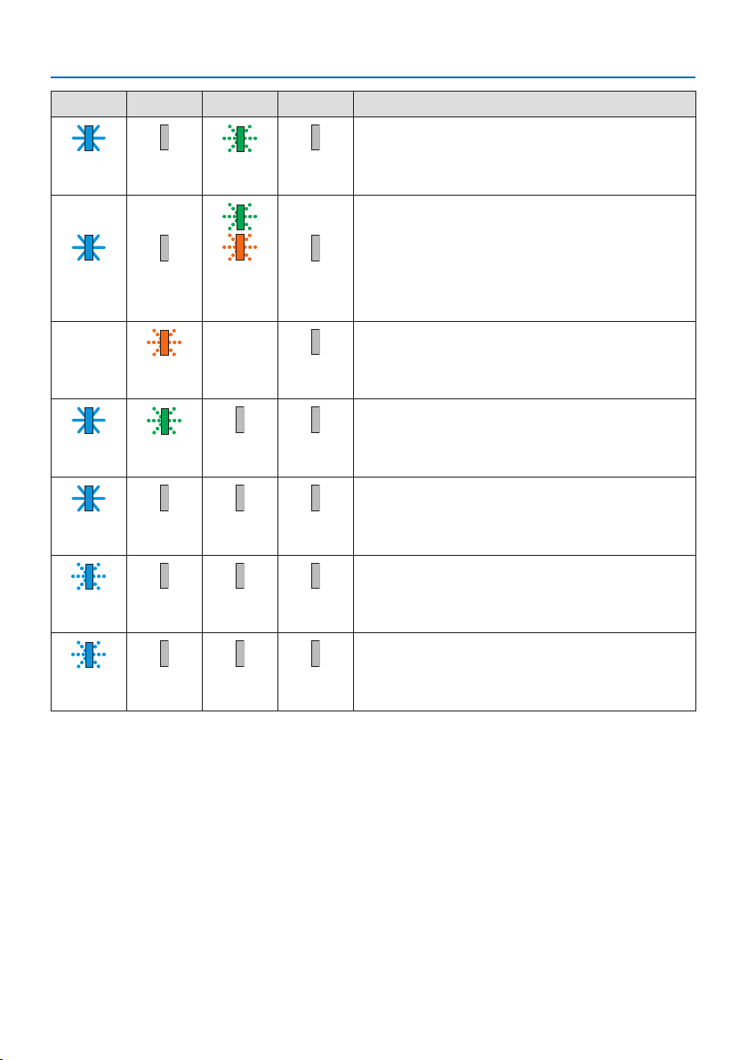
8. Appendix
192
POWER STATUS LIGHT TEMP. Projector status
Powered state ([REF. LIGHT MODE] is [ECO1] or [ECO2])
Blue
(Light)
OGreen
(Blink*
3
)
O
Powered state ([REF. LIGHT MODE] is [BOOST])
Blue
(Light)
OGreenand
orange
(Blink*
4
)
O
[LENS CALIBRATION] implement request.
StatusvariesOrange
(Blink*
5
)
StatusvariesO
Performing the lens calibration
Blue
(Light)
Green
(Blink*
5
)
StatusvariesO
Shutter function is activating
Blue
(Light)
StatusvariesOO
[OFF TIMER] is activated, [OFF] time as the [PROGRAM
TIMER] is activated (Powered state)
Blue
(Blink*
3
)
OStatusvariesO
Preparing for powering [ON]
Blue
(Blink*
5
)
OOO
*1 Repetition to light on for 1.5 seconds / off for 1.5 seconds
*2 Repetition to light on for 1.5 seconds / off for 7.5 seconds
*3 Repetition to light on for 2.5 seconds / off for 0.5 seconds
*4 Lit in green for 2.5 seconds/lit in orange for 0.5 seconds repeatedly
*5 Repetition to light on for 0.5 seconds / off for 0.5 seconds / on for 0.5 seconds / off for 2.5 seconds
*6 Repetition to light on for 0.5 seconds / off for 0.5 seconds
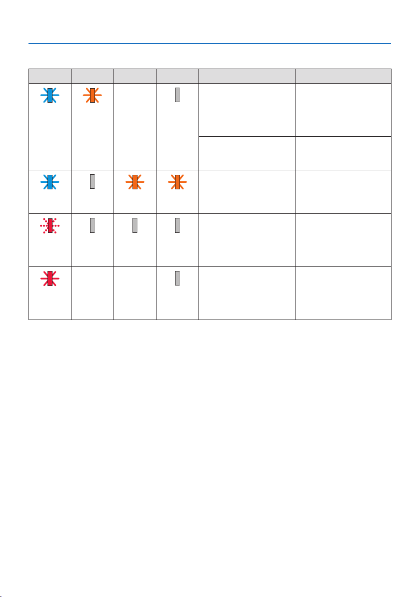
8. Appendix
193
Indicator Message (Error message)
POWER STATUS LIGHT TEMP. Projector status Procedure
A button has been
pressed while the [CON-
TROL PANEL LOCK] is
activated.
The [CONTROL PANEL
LOCK] is activated. The
setting must be canceled
to operate the projector.
(→ page 137)
Blue
(Light)
Orange
(Light)
StatusvariesO
ID numbers for the
projector and the remote
control do not match.
Check the [CONTROL ID]
(→ page
138)
Temperature problem (In
the Forced ECO)
Ambient temteprature
is high. Lower the room
temperature.
Blue
(Light)
OOrange
(Light)
Orange
(Light)
Temperature problem Ambient temperature
is out of the operation
temperature. Check if any
obstruction stays near the
exhaust vent.
Red
(Blink*
7
)
OOO
Error requiring service
support
Contact your dealer or
service personnel. Make
sure to check and inform
indicator status for asking
to repair.
Red
(Light)
StatusvariesStatusvariesO
*7 Repetition to light on for 0.5 seconds / off for 0.5 seconds
When the thermal protector is activated:
When inside temperature of the projector becomes too high or low, the POWER indicator start to
red blink in a short cycle. After this happened, the thermal protector will activate and the projector
may be turned off.
Inthiscase,pleasetakethebelowmeasures:
•Pulloutthepowerplugfromthewallinlet.
•Placetheprojectorincoolplaceifithasbeenplacedinhighambienttemperature.
•Cleantheexhaustventifdusthasaccumulatedon.
•Leavetheprojectorforaboutonehouruntilinsidetemperaturegetslower.

8. Appendix
194
Common Problems & Solutions
(→ “Indicator Message” on page
191.)
Problem Check These Items
Does not turn on or shut
down
•Checkthatthepowercordispluggedinandthatthepowerbuttonontheprojectorcabinetorthe
remotecontrolison.(→ pages
17,20)
•Checktoseeiftheprojectorhastemperatureerror,Ifprojectorinsidetemperatureistoohotorcool,
itdisabledtoturnontheprojectorastheprotection.Waitforamomentandtryturnontheprojector
again.
•Set[FANMODE]to[HIGHALTITUDE]whenusingtheprojectorataltitudesapproximately5500
feet/1700metersorhigher.Usingtheprojectorataltitudesapproximately5500feet/1700meters
orhigherwithoutsettingto[HIGHALTITUDE]cancausetheprojectortooverheatandtheprojector
couldshutdown.Ifthishappens,waitacoupleminutesandturnontheprojector.(→ page 127)
Ifyouturnontheprojectorimmediatelyafterthelightmoduleisturnedo,thefansrunwithout
displayinganimageforsometimeandthentheprojectorwilldisplaytheimage.Waitforamoment.
•Incaseit’shardtothinkthetroubleisnotcausedontheabovementionedconditions,unplugthe
powercordfromtheoutlet.Thenwait5minutesbeforepluggingitinagain.(→ page 37)
Willturno•Ensurethatthe[OFFTIMER],[AUTOPOWEROFF]or[PROGRAMTIMER]iso.(→ page
133,154)
No picture •Checkiftheappropriateinputisselected.(→ page
23)Ifthereisstillnopicture,presstheINPUT
buttonoroneoftheinputbuttonsagain.
•Ensureyourcablesareconnectedproperly.
•Usemenustoadjustthebrightnessandcontrast.(→ page 100)
•Isthe[POWERONSHUTTER]intheon-screenmenusetto[CLOSE]?
•CheckthattheSHUTTER(lensshutter)orAV-MUTE(imageo)buttonsarenotpressed.
•Resetthesettingsoradjustmentstofactorypresetlevelsusingthe[RESET]intheMenu.(→ page
155)
•EnteryourregisteredkeywordiftheSecurityfunctionisenabled.(→ page 50)
•IftheHDMIinputortheDisplayPortsignalcannotbedisplayed,trythefollowing.
-Reinstallyourdriverforthegraphicscardbuiltinyourcomputer,orusetheupdateddriver.
Forreinstallingorupdatingyourdriver,refertotheuserguideaccompaniedwithyourcomputeror
graphicscard,orcontactthesupportcenterforyourcomputermanufacturer.
InstalltheupdateddriverorOSonyourownresponsibility.
Wearenotliableforanytroubleandfailurecausedbythisinstallation.
•ThesignalmaynotbesupporteddependingontheHDBaseTtransmissiondevice.Inaddition,RS232C
interfacemaynotbesupported.
•BesuretoconnecttheprojectorandnotebookPCwhiletheprojectorisinstandbymodeandbefore
turningonthepowertothenotebookPC.
InmostcasestheoutputsignalfromthenotebookPCisnotturnedonunlessconnectedtothe
projectorbeforebeingpoweredup.
*Ifthescreengoesblankwhileusingyourremotecontrol,itmaybetheresultofthecomputer’s
screen-saverorpowermanagementsoftware.
•Seealsothepage196.
Picturesuddenlybecomes
dark
•CheckiftheprojectorisintheForcedECOmodebecauseoftoohighambienttemperature.Ifthisis
thecase,lowertheinternaltemperatureoftheprojectorbyselecting[HIGH]for[FANMODE].(→
page
127)

8. Appendix
195
Problem Check These Items
Color tone or hue is unusual •Checkifanappropriatecolorisselectedin[WALLCOLOR].Ifso,selectanappropriateoption.(→
page
127)
•Adjust[HUE]in[PICTURE].(→ page 100)
Imageisn’tsquaretothe
screen
•Repositiontheprojectortoimproveitsangletothescreen.(→ page
26)
•Perform[GEOMETRICCORRECTION]whenthetrapezoidisdistorted.(→ page 45)
Pictureisblurred•Adjustthefocus.(→ page
29)
•Repositiontheprojectortoimproveitsangletothescreen.(→ page 26)
•Ensurethatthedistancebetweentheprojectorandscreeniswithintheadjustmentrangeofthe
lens.(→ page 171)
•Hasthelensbeenshiftedbyanamountexceedingtheguaranteedrange?(→ page 175)
•Condensationmayformonthelensiftheprojectoriscold,broughtintoawarmplaceandisthen
turnedon.Shouldthishappen,lettheprojectorstanduntilthereisnocondensationonthelens.
Flickerappearsonscreen•Set[FANMODE]tootherthan[HIGHALTITUDE]modewhenusingtheprojectorataltitudesapproxi-
mately5500feet/1700metersorlower.Usingtheprojectorataltitudeslessthanapproximately5500
feet/1700metersandsettingto[HIGHALTITUDE]cancausethelightmoduletoovercool,causing
theimagetoicker.Switch[FANMODE]to[AUTO].(→ page
127)
Imageisscrollingvertically,
horizontallyorboth
•Checkthecomputer’sresolutionandfrequency.Makesurethattheresolutionyouaretryingtodisplay
issupportedbytheprojector.(→ page
177)
•AdjustthecomputerimagemanuallywiththeHorizontal/Verticalinthe[IMAGEOPTIONS].(→ page
102)
Remotecontroldoesnot
work
•Installnewbatteries.(→ page
13)
•Makesuretherearenoobstaclesbetweenyouandtheprojector.
•Standwithin20m/787inchoftheprojector.(→ page 14)
Indicatorislitorblinking•SeetheIndicatorMessage.(→ page
191)
CrosscolorinRGBmode•Adjustthecomputerimagemanuallywith[CLOCK]/[PHASE]in[IMAGEOPTIONS]inthemenu.(→
page
101)
For more information contact your dealer.

8. Appendix
196
If there is no picture, or the picture is not displayed correctly.
Power on process for the projector and the PC.
Be sure to connect the projector and notebook PC while the projector is in standby mode and before
turning on the power to the notebook PC.
In most cases the output signal from the notebook PC is not turned on unless connected to the
projector before being powered up.
NOTE:
•Youcancheckthehorizontalfrequencyofthecurrentsignalintheprojector’smenuunderInformation.Ifitreads“0kHz”,thismeans
thereisnosignalbeingoutputfromthecomputer.(→ page 156orgotonextstep)
Enabling the computer’s external display.
Displaying an image on the notebook PC’s screen does not necessarily mean it outputs a signal to
the projector. When using a PC compatible laptop, a combination of function keys will enable/dis-
able the external display. Usually, the combination of the “Fn” key along with one of the 12 function
keys gets the external display to come on or off. For example, NEC laptops use Fn + F3, while Dell
laptops use Fn + F8 key combinations to toggle through external display selections.
Non-standard signal output from the computer
If the output signal from a notebook PC is not an industry standard, the projected image may not be
displayed correctly. Should this happen, deactivate the notebook PC’s LCD screen when the projector
display is in use. Each notebook PC has a different way of deactivate/reactivate the local LCD screens
as described in the previous step. Refer to your computer’s documentation for detailed information.
Image displayed is incorrect when using a Mac
When using a Mac with the projector, set the DIPswitch of the Mac adapter (not supplied with the
projector) according to your resolution. After setting, restart your Mac for the changes to take affect.
For setting display modes other than those supported by your Mac and the projector, changing
the DIP switch on a Mac adapter may bounce an image slightly or may display nothing. Should this
happen, set the DIP switch to the 13" fixed mode and then restart your Mac. After that, restore the
DIP switches to a displayable mode and then restart the Mac again.
NOTE:
•AVideoAdaptercablemanufacturedbyAppleComputerisneededforaMacBookwhichdoesnothaveaminiD-Sub15-pincon-
nector.
Mirroring on a MacBook
WhenusingtheprojectorwithaMacBook,outputmaynotbesetto1920×1200unless“mirroring”
is off on your MacBook. Refer to owner’s manual supplied with your Mac computer for mirroring.
Folders or icons are hidden on the Mac screen
Folders or icons may not be seen on the screen. Should this happen, select [View] → [Arrange] from
the Apple menu and arrange icons.

8. Appendix
197
8-8. PC Control Codes and Cable Connection
PC Control Codes
Function Code Data
POWER ON 02H 00H 00H 00H 00H 02H
POWER OFF 02H 01H 00H 00H 00H 03H
INPUT SELECT HDMI1 02H 03H 00H 00H 02H 01H A1H A9H
INPUT SELECT HDMI2 02H 03H 00H 00H 02H 01H A2H AAH
INPUT SELECT DisplayPort 02H 03H 00H 00H 02H 01H A6H AEH
INPUT SELECT COMPUTER 02H 03H 00H 00H 02H 01H 01H 09H
INPUT SELECT HDBaseT 02H 03H 00H 00H 02H 01H BFH C7H
PICTURE MUTE ON 02H 10H 00H 00H 00H 12H
PICTURE MUTE OFF 02H 11H 00H 00H 00H 13H
SOUND MUTE ON 02H 12H 00H 00H 00H 14H
SOUND MUTE OFF 02H 13H 00H 00H 00H 15H
NOTE:
•ContactyourlocaldealerforafulllistofthePCControlCodesifneeded.
Cable Connection
Communication Protocol
Baud rate 115200/38400/19200/9600/4800 bps
Data length 8 bits
Parity No parity
Stop bit 1 bit
X on/off None
Communications procedure Full duplex
NOTE:
•Dependingontheequipment,alowerbaudratemayberecommendedforlongcableruns.
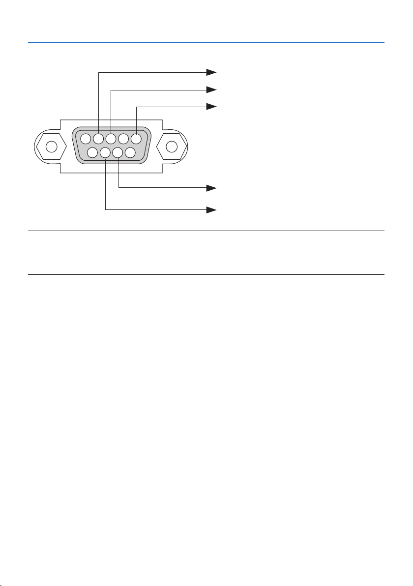
8. Appendix
198
PC Control Terminal (D-Sub 9P)
15243
67 98
To GND of PC
To RxD of PC
To TxD of PC
To RTS of PC
To CTS of PC
NOTE:
•Pins1,4,6and9arenoused.
•Jumper“RequesttoSend”and“CleartoSend”togetheronbothendsofthecabletosimplifycableconnection.
•Forlongcablerunsitisrecommendedtosetcommunicationspeedwithinprojectormenusto9600bps.
8. Appendix
199
8-9. About the ASCII Control Command
This device supports the common ASCII Control Command for controlling our projector and monitor.
Please visit our web site for detailed information about the command.
https://www.nec-display.com/dl/en/pj_manual/lineup.html
How to connect with an external device
There are two methods to connect the projector with an external device such as a computer.
1. Connection thru the serial port.
Connects the projector to a computer by a serial cable (a cross cable).
2. Connection via network (LAN/HDBaseT)
Connects the projector to a computer by a LAN cable.
Concerning to the type of LAN cable, please ask to your network administrator.
Connection interface
1. Connection thru the serial port.
Communication Protocol
Item Information
Baud rate 115200/38400/19200/9600/4800 bps
Data length 8 bits
Parity bit No parity
Stop bit 1 bit
Flow control None
Communications procedure Full duplex
2. Connection via network
Communication Protocol (Connection via LAN)
Item Information
Communication speed Set automatically (10/100 Mbps)
Supported standard IEEE802.3 (10BASE-T)
IEEE802.3u (100BASE-TX, Auto-Negotiation)
Use the TCP port number 7142 for transmitting and receiving command.
Communication Protocol (Connection via HDBaseT)
Item Information
Communication speed 100 Mbps
Supported standard IEEE802.3u (100BASE-TX, Auto-Negotiation)
Use the TCP port number 7142 for transmitting and receiving command.

8. Appendix
200
Parameters for this device
Input command
Input terminal Response Parameter
HDMI1 hdmi1 hdmi1 or hdmi
HDMI2 hdmi2 hdmi2
DisplayPort displayport displayport or displayport1
COMPUTER computer One among computer, computer1, vga, vga1, rgb, and rgb1
HDBaseT hdbaset hdbaset or hdbaset1
Status command
Response Error Status
error:tempTemperature error
error:fanFan trouble
error:lightLight source trouble
error:systemSystem trouble

8. Appendix
201
8-10. List of Art-Net DMX parameters
Function Behavior Parameter Note
POWER OFF 0–63
No operation 64–191
ON 192–255
INPUT No operation 0–7
HDMI1 8–15
No operation 16–23
HDMI2 24–31
No operation 32–39
DisplayPort 40–47
No operation 48–55
COMPUTER 56–63
No operation 64–71
HDBaseT 72–79
No operation 80–255
BLANK OFF 0–63
No operation 64–191
ON 192–255
SHUTTER OPEN 0–63
No operation 64–191
CLOSE 192–255
FREEZE OFF 0–63
No operation 64–191
ON 192–255
LIGHT ADJUST No operation 0–49
Adjusted value 50–100
No operation 101–255
LENS SHIFT(H) Adjust Left 0–63
Stop 64–191
Adjust Right 192–255
LENS SHIFT(V) Adjust Down 0–63
Stop 64–191
Adjust Up 192–255
FOCUS Adjust (−) 0–63
Stop 64–191
Adjust (+) 192–255
ZOOM Adjust (−) 0–63
Stop 64–191
Adjust (+) 192–255
KEYSTONE(H) No operation Adjust +/− with 128 as the center (adjust-
ment Adjusted value value 0).
Adjusted value
No operation
KEYSTONE(V) No operation Adjust +/− with 128 as the center (adjust-
ment value 0).
Adjusted value
No operation

8. Appendix
202
Function Behavior Parameter Note
LOCK Inoperable 0–127Disables the Art-Net function.
Operable 128–255Enables the Art-Net function.
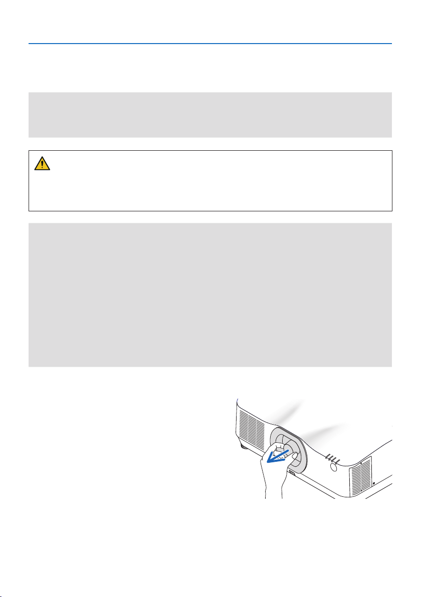
8. Appendix
203
8-11. Mounting a lens (separately sold)
Nine separate bayonet style lenses can be used with this projector. The descriptions here are for
the NP41ZL lens. Mount other lenses in the same manner.
Important:
•Afterinstallingorreplacingthelensunit,presstheZOOM/L-CALIB.buttonontheprojectortocarryout[LENSCALIBRATION].By
carryingout[LENSCALIBRATION],theadjustmentrangeofthelensshiftiscalibrated.
•[LENSCALIBRATION]isnotavailableforthelensunitNP44ML.
WARNING:
(1) Turn off the power and wait for the cooling fan to stop, (2) disconnect the power cord and
wait for the unit to cool before mounting or removing the lens. Failure to do so can result in eye
injury, electric shock, or burn injuries.
Important:
•Theprojectorandlensesaremadeofprecisionparts.Donotsubjectthemtoshockorexcessiveforces.
•Removetheseparatelysoldlenswhenmovingtheprojector.Ifnot,thelenscouldbesubjecttoshockwhiletheprojectorisbeing
moved,damagingthelensandthelensshiftmechanism.
•Whendismountingthelensfromtheprojector,returnthelenspositiontothehomepositionbeforeturningothepower.Failure
todosomaypreventthelensfrombeingmountedordismountedbecauseofnarrowspacebetweentheprojectorandthelens.
•Nevertouchthelenssurfacewhiletheprojectorisoperating.
•Beverycarefulnottoletdirt,grease,etc.,onthelenssurfaceandnottoscratchthelenssurface.
•Performtheseoperationsonaatsurfaceoverapieceofcloth,etc.,topreventthelensfromgettingscratched.
•Whenleavingthelensotheprojectorforlongperiodsoftime,mountthedustcapontheprojectortopreventdustordirtfrom
gettinginside.
•AfterinstallingthelensunitNP44MLontheprojector,besuretosecureittotheprojectorusingthesupportkit(NP02LK)sold
separately.Formoredetails,seethehandlinginstructionsofthesupportkit.
Mounting
1. Remove the dust cap from the projector.
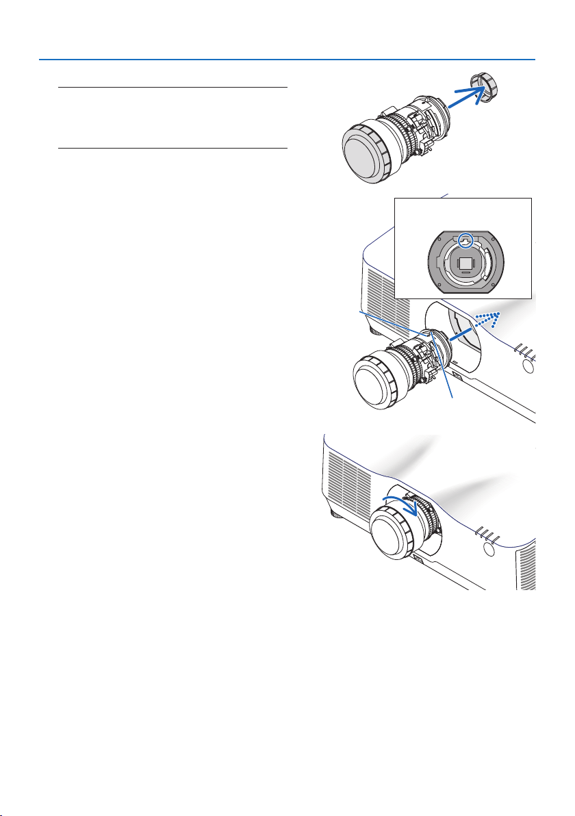
8. Appendix
204
2. Remove the lens cap on the back of the lens.
NOTE:
•Makesuretoremovethelenscapattheunitbackside.If
thelensunitwiththelenscapremainingonisinstalled
ontheprojector,itmaycauseofmalfunction.
3. Insert the lens onto the projector facing the
arrow on the lens-label upward.
Insert the lens slowly all the way in.
Guiding notch
Protrusion
Arrow
4. Turn the lens clockwise.
Turn until a click is heard.
The lens is now fastened onto the projector.
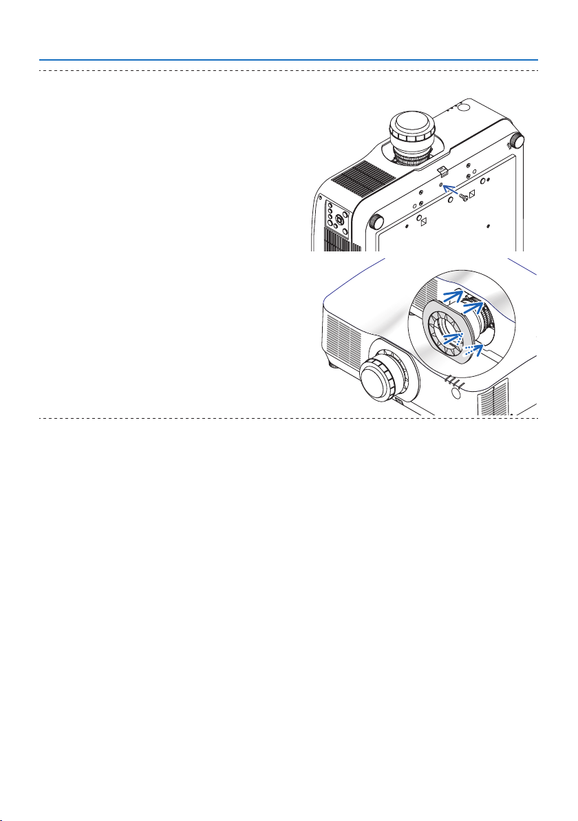
8. Appendix
205
TIP:
•Fastenthelenstheftpreventionscrewincludedwiththeprojec-
tortothebottomoftheprojectorsothatthelenscannotbe
removedeasily.
•Attachtheenclosedlensmaskifyouwanttohidethegap
betweentheprojectorandlens.
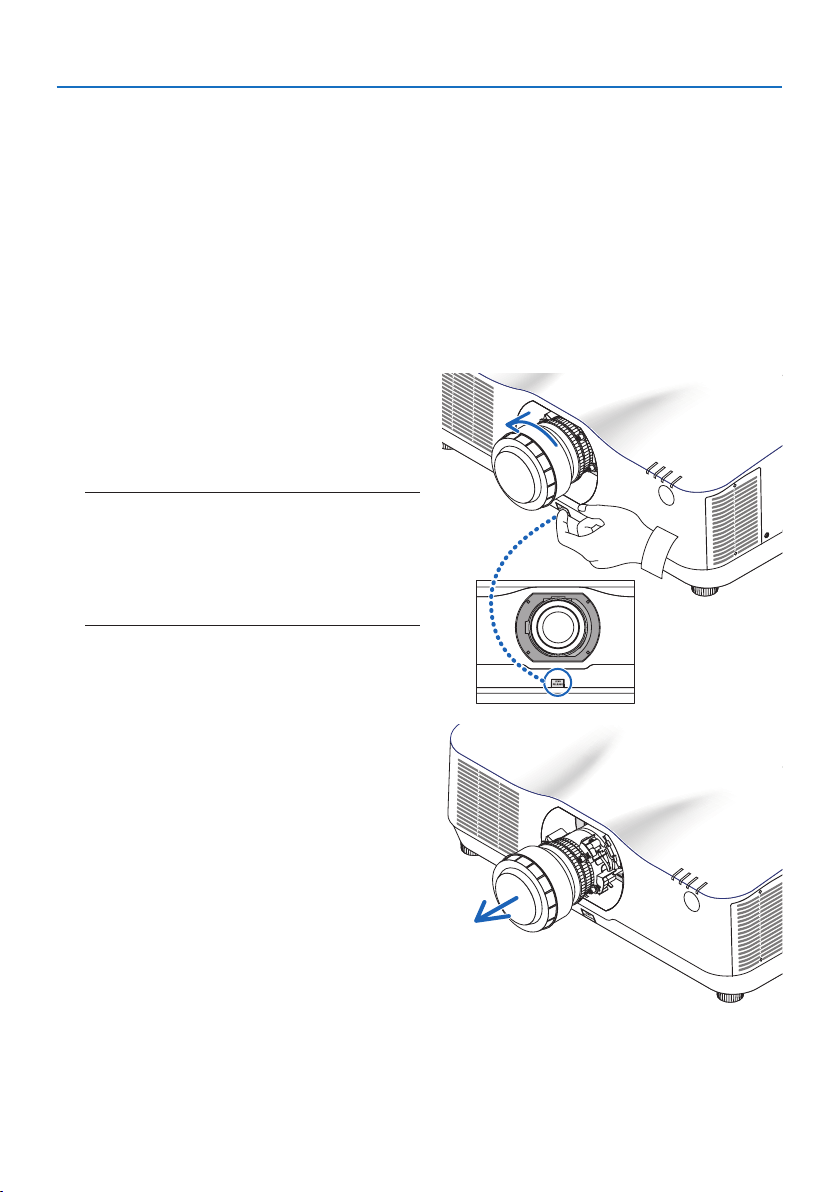
8. Appendix
206
Removing
Preparations:
1. Turn on the projector and display an image.
2. Press and hold the SHIFT/HOME POSITION button over 2 seconds. The lens position will be
moved to the home position.
3. Turn off the main power switch, and then unplug the power cord.
4. Wait until the projector cabinet is cool enough to handle.
5. If the lens theft prevention screw has been set on, remove it. In addition, remove the lens mask
if one is fitted.
1. While pressing the lens release button at
the bottom of lens mounting section on the
projector’s front panel fully in, turn the lens
counterclockwise.
The lens comes off.
NOTE:
•Checkthefollowingareasifthelensunitcannotbe
removedevenwhenthelensreleasebuttonispressed.
1.Thelensreleasebuttonmaybelockedsometimes.In
thatcase,turnthelensfullytotheright.Thelensrelease
buttonlockwillbereleased.
2. Slowlypullthelensotheprojector.
•Afterremovingthelens,mountthelens
caps (front and back) included with the
lens before storing the lens.
•Ifnolensisgoingtobemountedonthe
projector, mount the dust cap included
with the projector.
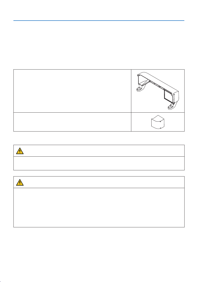
8. Appendix
207
8-12. Attaching the option cover (separately sold)
Model name of option cover
NP13CV-W for PA1004UL-W/PA804UL-W
NP13CV-B for PA1004UL-B/PA804UL-B
The option covers A and B are packaged with the option cover NP13CV-W and NP13CV-B.
For the following cases, attach the separately sold option cover to the projector.
Option cover A
•Tomaketheappearancecleanbycoveringtheconnected
cables
•Toinstalltheprojectorwithitsrearupwardordownward
Option cover B
•Toinstalltheprojectorwithitsexhaustventsupwardordown-
ward
For installation angles required to attach the option cover, refer to page xix.
WARNING
• Wheninstallingtheprojectoratanangle,besuretoattachtheoptioncoverforsafety.
• Besuretoattachtheoptioncovertotheprojectorwhentheprojector'spoweristurnedon.
CAUTION
About option cover
•Afterattachingtheoptioncovertotheprojector,besuretotightenthescrews.Ifyoufailto
do so, the option cover may come off and cause injury, or the option cover may fall and cause
damage.
•Donotbundlethepowercordandplaceitundertheoptioncover.Doingsocouldleadtore.
•Donotmovetheprojectorbyholdingtheoptioncoverordonotuseexcessiveforcetothe
option cover. Doing so can cause damage to the option cover, resulting in injury.
Preparations:
•Connectthecablestotheprojector(theconnectioncordsareomittedfromthediagrams).
At this moment, do not connect the power cord.
•PrepareaPhillipsscrewdriver.
•Placetheprojectoronasoftclothsoasnottoscratchthecabinetsurface.
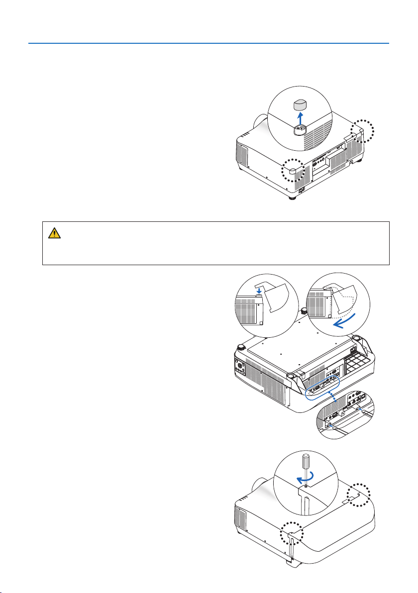
8. Appendix
208
•OptioncoverA
Mounting
1. Remove the two corner caps from the pro-
jector.
•Keeptheremovedcornercapsforfuture
use.
2. Turn over the projector.
CAUTION
•Formovingtheprojector,makesureyouhaveatleasttwopeople.Attemptingtomove
the projector alone could result in back pain or other injuries.
3. Attach the option cover A to the projector.
① Shorten the projector tilt foot to the mini-
mum height.
② Hang the two hooks of the option cover A
on the projector tilt foot.
③ Align the two screw fixing parts of the op-
tion cover A with the place of the corner
caps that were removed at step 1.
At this time, the two hooks in the option
cover will enter the grooves in the projec-
tor.
•Ifthehooksdonotentereasily,checkthe
positions of the grooves. Do not press the
hooks in by force.
•Becarefulnottoletthecablesgetpinched
by the option cover A.
4. Turn the two option cover A screws clock-
wise.
•Tightenthescrewssecurely.
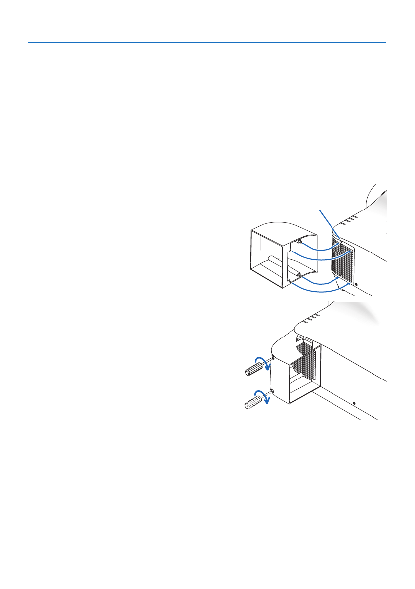
8. Appendix
209
Removing
1. Turn the two option cover A screws counterclockwise until it turns loosely.
•Thescrewsarenotremovable.
2. Remove the option cover A.
Hold up the option cover A to release its two hooks from projector tilt foot.
3. Attach the two corner caps to the projector.
•OptioncoverB
Mounting
1. Press the two protrusions on option cover B
against the slits in the projector’s exhaust
vent.
•Lineuptheupperprotrusionwiththeslit
at the very top, the lower protrusion with
the slit at the very bottom.
Screw hole
2. Supporting option cover B by hand, turn
the two screws clockwise to tighten them.
•Tightenthescrewssecurely.
Removing
1. Supporting option cover B by hand, turn the two screws counterclockwise to loosen them
until they turn freely.
•Thescrewsarenotremovable.
2. Remove the option cover B.
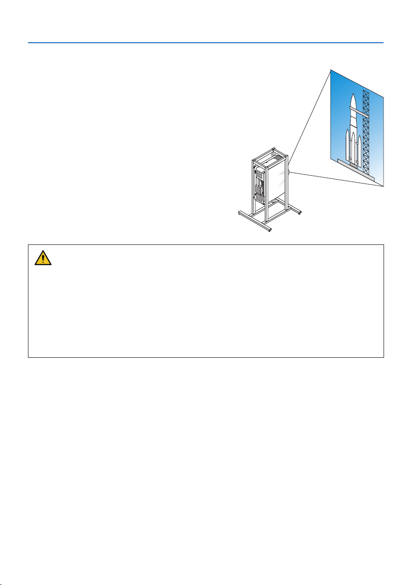
8. Appendix
210
8-13. Portrait projection (vertical orientation)
Portrait screens from a computer can be projected
by installing the projector in a vertical orientation.
Precautions during installation
•Pleasedonotinstalltheprojectorinaverticalorientationontopoftheoorortableonits
own. If not, the projector may fall over, resulting in injury, damage or malfunction. Also, the
exhaust vent may be obstructed, resulting in the projector getting warm and the possibility
of fire and malfunction occurring.
•Astandforsupportingtheprojectorneedstobemadeforportraitprojectionandforinstalling
the projector in universal angle. In this case, the stand must be designed such that the center
of gravity of the projector is located well within the legs of the stand. If not, the projector may
fall over and result in injury, damage and malfunction.
Design and manufacturing conditions for the stand
Please engage an installation service provider for the design and manufacture of the customized
stand to be used for portrait projection. Please ensure that the following are complied with when
designing the stand.
1. Secure sufficient space between the projector and the floor. (→ next page)
2. Use the four screw holes at the back of the projector to secure it to the stand.
Screwholecenterdimension:width300mm,lengthwisepitch150mm
Screwholedimensionontheprojector:M4withamaximumdepthof8mm.
* Please design the stand such that the rear legs at the back of the projector do not contact
the stand. The front legs can be turned and removed.
3. Horizontal adjustment mechanism (for example, bolts and nuts in four locations)
4. Please design the stand such that it does not topple over easily.
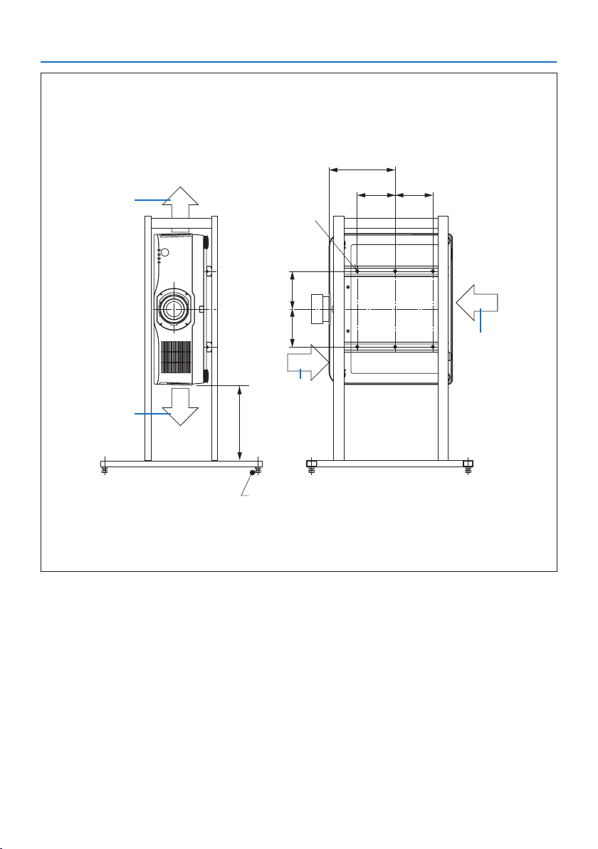
8. Appendix
211
Reference drawings
* The drawing showing the dimensional requirements is not an actual stand design drawing.
(Unit:mm)
[FrontView][SideView]
Screwholesfor6-M4use
300orgreater**
262
150 150
Horizontaladjuster
Exhaust
Intakeair
Intakeair
Exhaust
150 150
** The example shows the right side of the body (side where the control unit is located) facing downwards.
To make the left side of the body (side where the label is pasted) face downwards, leave a space of 200
mm or more.
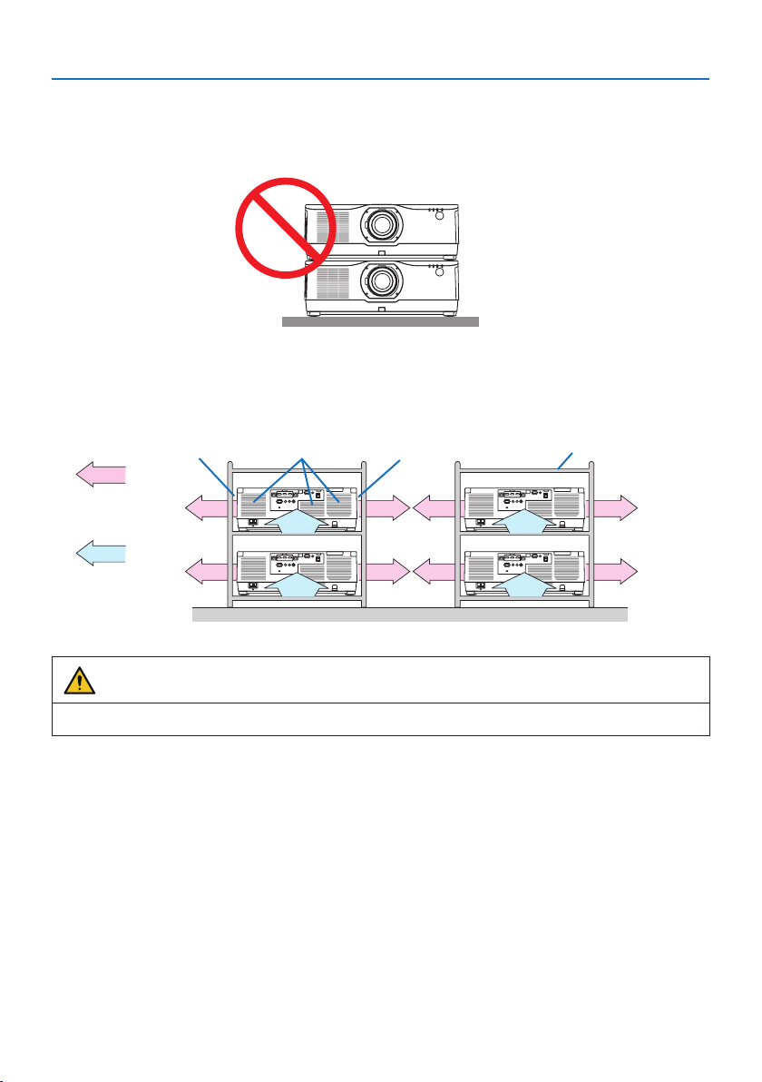
8. Appendix
212
8-14. For multi-Screen projection
•Theprojectordoesnotsupportstackinstallation.Donotstackprojectorsdirectlyontopofeach
other. Failure to do so may cause damage or failure.
•Whenusingmultipleprojectorstogetherformulti-screenprojection,providesucientspace
around the projectors for air intake and exhaust. When the intake and exhaust vents are obstructed,
the temperature inside the projector will rise and this may result in a malfunction.
Exhaust ventExhaust vent CabinetIntake vent
Air exhaust
Air intake
Back Back
WARNING
Please use a sturdy cabinet that can withstand the weight of the projector for the installation.

8. Appendix
213
8-15. Troubleshooting Check List
Before contacting your dealer or service personnel, check the following list to be sure repairs are
needed also by referring to the “Troubleshooting” section in your user’s manual. This checklist below
will help us solve your problem more efficiently.
* Print this page and the next page for your check.
Frequency of occurrence:
□always□sometimes(Howoften? ) □ other ( )
Power
□
No power (POWERindicatordoesnotlightblue).Seealso“Status
Indicator(STATUS)”.
□
Powercord’splugisfullyinsertedintothewalloutlet.
□
NopowereventhoughyoupressandholdthePOWERbutton.
□
Shutdownduringoperation.
□
Powercord’splugisfullyinsertedintothewalloutlet.
□
[AUTOPOWEROFF]isturnedo(onlymodelswiththe[AUTO
POWEROFF]function).
□
[OFFTIMER]isturnedo(onlymodelswiththe[OFFTIMER]
function).
Video and Audio
□
NoimageisdisplayedfromyourPCorvideoequipmenttothe
projector.
□
StillnoimageeventhoughyouconnecttheprojectortothePC
rst,thenstartthePC.
□
EnablingyournotebookPC’ssignaloutputtotheprojector.
•Acombinationoffunctionkeyswillenable/disablethe
externaldisplay.Usually,thecombinationofthe“Fn”key
alongwithoneofthe12functionkeysturnstheexternal
displayonoro.
□
Noimage(blueorblackbackground,nodisplay).
□
StillnoimageeventhoughyoupresstheAUTOADJ.button.
□
Stillnoimageeventhoughyoucarryout[RESET]intheprojec-
tor’smenu.
□
Signalcable’splugisfullyinsertedintotheinputterminal
□
Amessageappearsonthescreen.
(_____________________________________)
□
Thesourceconnectedtotheprojectorisactiveandavailable.
□
Stillnoimageeventhoughyouadjustthebrightnessand/or
thecontrast.
□
Inputsource’sresolutionandfrequencyaresupportedbythe
projector.
□
Imageistoodark.
□
Remainsunchangedeventhoughyouadjustthebrightness
and/orthecontrast.
□
Imageisdistorted.
□
Imageappearstobetrapezoidal(unchangedeventhoughyou
carryoutthe[KEYSTONE]adjustment).
□
Partsoftheimagearelost.
□
StillunchangedeventhoughyoupresstheAUTOADJ.button.
□
Stillunchangedeventhoughyoucarryout[RESET] in the
projector’smenu.
□
Imageisshiftedintheverticalorhorizontaldirection.
□
Horizontalandverticalpositionsarecorrectlyadjustedona
computersignal.
□
Inputsource’sresolutionandfrequencyaresupportedbythe
projector.
□
Somepixelsarelost.
□
Imageisickering.
□
StillunchangedeventhoughyoupresstheAUTOADJ.button.
□
Stillunchangedeventhoughyoucarryout[RESET] in the
projector’smenu.
□
Imageshowsickeringorcolordriftonacomputersignal.
□
Stillunchangedeventhoughyouchange[FANMODE]from[HIGH
ALTITUDE]to[AUTO].
□
Imageappearsblurryoroutoffocus.
□
Stillunchangedeventhoughyoucheckedthesignal’sresolution
onPCandchangedittoprojector’snativeresolution.
□
Stillunchangedeventhoughyouadjustedthefocus.
□
Nosound.
□
Audiocableiscorrectlyconnectedtotheaudioinputofthe
projector.
□
Stillunchangedeventhoughyouadjustedthevolumelevel.
□
AUDIOOUTisconnectedtoyouraudioequipment(onlymodels
with the AUDIOOUTterminal).
Other
□
Remotecontroldoesnotwork.
□
Noobstaclesbetweenthesensoroftheprojectorandthe
remotecontrol.
□
Projectorisplacednearauorescentlightthatcandisturbthe
infraredremotecontrols.
□
Batteriesarenewandarenotreversedininstallation.
□
Buttonsontheprojectorcabinetdonotwork(onlymodelswiththe
[CONTROLPANELLOCK] function)
□
[CONTROLPANELLOCK]isnotturnedonorisdisabledinthe
menu.
□
StillunchangedeventhoughyoupressandholdtheEXITbutton
over10seconds.
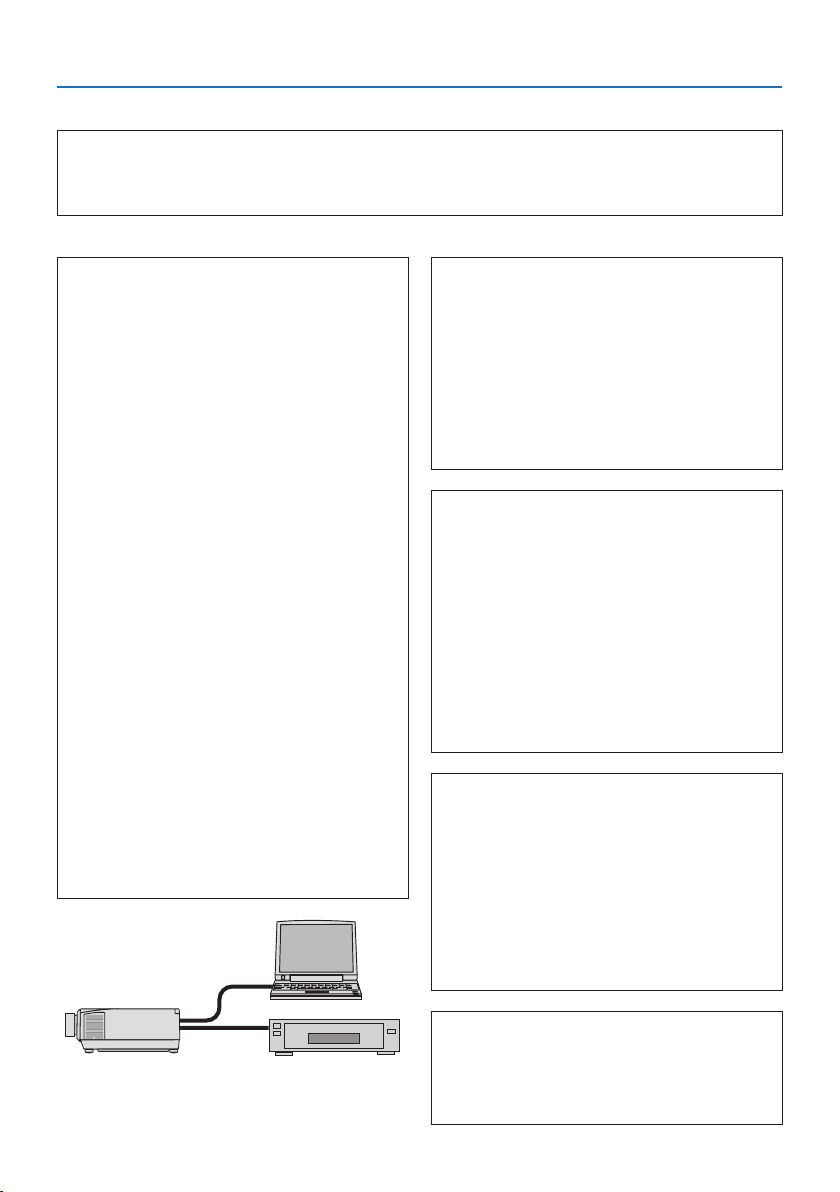
8. Appendix
214
In the space below please describe your problem in detail.
Information on application and environment where your projector is used
Projector
Modelnumber:
SerialNo.:
Date of purchase:
Lightmoduleoperatingtime(hours):
REF.LIGHTMODE: □ BOOST □ NORMAL
□ ECO1 □ ECO2
Informationoninputsignal:
Horizontalsynchfrequency[]kHz
Verticalsynchfrequency[ ]Hz
SynchpolarityH□ (+) □ (−)
V □ (+) □ (−)
Synchtype□Separate □ Composite
□SynconGreen
IndicatorMessage:
□ POWERBlinksin□ Blue □Green□ Orange □Red
[]cycles
Lights in □ Blue □Green□ Orange □Red
□ STATUSBlinksin□ Blue □Green□ Orange □Red
[]cycles
Lights in □ Blue □Green□ Orange □Red
□ LIGHTBlinksin□ Blue □Green□ Orange □Red
[]cycles
Lights in □ Blue □Green□ Orange □Red
□ TEMP.Blinksin□ Blue □Green□ Orange □Red
[]cycles
Lights in □ Blue □Green□ Orange □Red
Remotecontrolmodelnumber:
Projector
PC
DVD player
Signal cable
NECstandardorothermanufacturer’scable?
Modelnumber:Length:inch/m
Distributionamplier
Modelnumber:
Switcher
Modelnumber:
Adapter
Modelnumber:
Installation environment
Screensize:inch
Screentype:□Whitematte □Beads□Polarization
□Wideangle □ High contrast
Throwdistance:feet/inch/m
Orientation: □ Ceiling mount □Desktop
Poweroutletconnection:
□Connecteddirectlytowalloutlet
□Connectedtopowercordextenderorother(thenumberof
connectedequipment______________)
□Connectedtoapowercordreelorother(thenumberof
connectedequipment______________)
Computer
Manufacturer:
Modelnumber:
NotebookPC□/Desktop□
Native resolution:
Refresh rate:
Videoadapter:
Other:
Video equipment
VCR,DVDplayer,Videocamera,Videogameorother
Manufacturer:
Modelnumber:

8. Appendix
215
8-16. REGISTER YOUR PROJECTOR! (for residents in the United States,
Canada, and Mexico)
Please take time to register your new projector. This will activate your limited parts and labor war-
ranty and InstaCare service program.
Visit our web site at
www.necdisplay.com, click on support center/register product and submit
your completed form online.
Upon receipt, we will send a confirmation letter with all the details you will need to take advantage
of fast, reliable warranty and service programs from the industry leader, NEC Display Solutions of
America, Inc.

©NECDisplaySolutions,Ltd.2020