Loading ...
Loading ...
Loading ...
SERVICE AND ADJUSTMENTS
_ WARNING: TO AVOID SERIOUS iNJURY, BEFORE PERFORMING ANY SERVICE OR ADJUSTMENTS:
Depress brake pedal fully and set parking brake.
" Place attachment clutch in "DISENGAGED" position.
" Turn ignition key to "STOP" and remove key.
" Make sure the blades and all moving parts have completely stopped.
" Disconnect spark plug wire from spark plug and place wirewhere it cannot come in contact with plug.
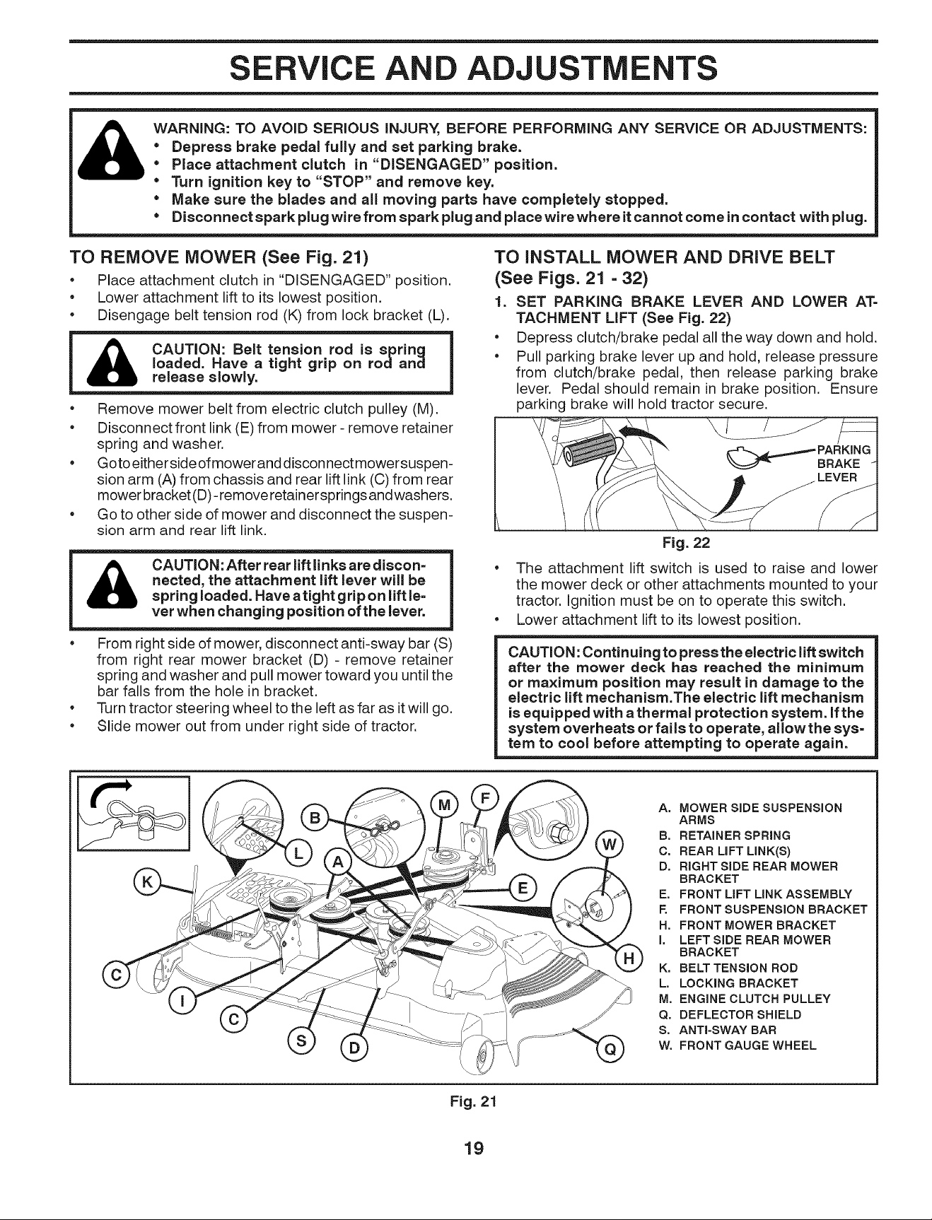
TO REMOVE MOWER (See Fig. 21)
Place attachment clutch in "DISENGAGED" position.
• Lower attachment lift to its lowest position.
• Disengage belt tension rod (K) from lock bracket (L).
I CAUTION: Belt tension rod is spring I
release slowly.
I loaded. Have a tight grip on rodand |
• Remove mower belt from electric clutch pulley (M).
• Disconnect front link (E) from mower - remove retainer
spring and washer.
• Goto eitherside ofmower anddisconnect mowersuspen-
sion arm (A) from chassis and rear lift link (0) from rear
mower bracket (D)- remove retainersprings andwashers.
• Go to other side of mower and disconnect the suspen-
sion arm and rear lift link.
&
CAUTION:After rear lift linksare discon=
netted, the attachment lift lever will be
spring loaded. Have atight grip on lift le-
ver when changing position of the lever.
From right side of mower, disconnect anti-sway bar (S)
from right rear mower bracket (D) - remove retainer
spring and washer and pull mower toward you until the
bar falls from the hole in bracket.
Turn tractor steering wheel to the left as far as itwill go.
Slide mower out from under right side of tractor.
TO INSTALL MOWER AND DRIVE BELT
(See Figs. 21 - 32)
1. SET PARKING BRAKE LEVER AND LOWER AT=
TACHMENT LIFT (See Fig. 22)
• Depress clutch/brake pedal all the way down and hold.
• Pull parking brake lever up and hold, release pressure
from clutch/brake pedal, then release parking brake
lever. Pedal should remain in brake position. Ensure
parking brake will hold tractor secure.
PARK,NG
Fig. 22
• The attachment lift switch is used to raise and lower
the mower deck or other attachments mounted to your
tractor. Ignition must be on to operate this switch.
• Lower attachment lift to its lowest position.
CAUTION: Continuing to press the electric liftswitch
after the mower deck has reached the minimum
or maximum position may result in damage to the
electric lift mechanism.The electric lift mechanism
is equipped with a thermal protection system. If the
system overheats or fails to operate, allow the sys=
tern to cool before attempting to operate again.
A. MOWER SIDE SUSPENSION
ARMS
B. RETAINER SPRING
C. REAR LIFT LINK(S)
D. RIGHT SIDE REAR MOWER
BRAC KET
E. FRONT LIFT LINK ASSEMBLY
F. FRONT SUSPENSION BRACKET
H. FRONT MOWER BRACKET
I. LEFT SIDE REAR MOWER
BRACKET
K. BELT TENSION ROD
L. LOCKING BRACKET
M. ENGINE CLUTCH PULLEY
Q. DEFLECTOR SHIELD
S, ANTI-SWAY BAR
W. FRONT GAUGE WHEEL
Fig. 21
19
Loading ...
Loading ...
Loading ...