Register
your product
www.kaercher.com/welcome
L
I
S
T
E
D
®
98013300-1
WA
R
N
I
N
G
PR
EC
A
U
T
I
O
N
/
A
TTE
N
TI
O
N
D
O
N
O
T
S
T
A
N
D
O
R
S
T
E
P
O
N
T
H
I
S
PL
A
T
F
O
R
M
9.801-330-K 04/27/22
English
TRS-SSG-503537 E/G

CONTENTS
2
Model Number ______________________________
Serial Number ______________________________
Date of Purchase ____________________________
The model and serial numbers will be found on a decal at tached
to the machine. You should record both serial number and date of
purchase and keep in a safe place for future ref er ence.
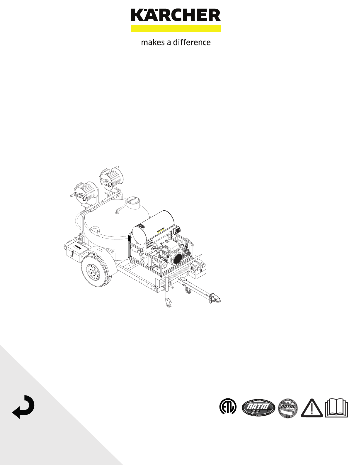
Kärcher TRS-SSG • Operators • 9.801-330.0-K
ORDER # 1.103-840.0
Important Trailer Safety Information 3-6
What to Check & How to Check 7-10
Important Pressure Safety Information 11-13
Pressure Washer Component Identifi cation 14
Pressure Washer Assembly Instructions 15
Pressure Washer Operating Instructions 16-17
Detergents & General Cleaning Techniques 18
Pressure Washer Shut Down & Clean-Up 19
Pressure Washer Storage 19
Pressure Washer Maintenance 20-22
Trailer preventative Maintenance 23
Pressure Washer Troubleshooting 24-27
Pressure Washer Preventative Maintenance 28
Notice
This trailer is equipped to meet applicable U.S. Federal safety standards. Check
local and state requirements regarding brakes and any additional equipment
that may be required. Any modifi cations or additions including load-equalizing
hitches, without written factory consent: usage in an abnormal manner includ-
ing overloading voids all manufacturers’ warranties and liability.
WARNING: This Owner's Manual contains safety information and
instructions for your trailer.
You must read this manual before loading or towing your trailer.
You must follow all safety precautions and instructions.

Kärcher TRS-SSG • Operators • 9.801-330.0-K
3
PRESSURE WASHER
OPERATOR’S MAN U AL
Referencing the Utility Trailer in this
Manual
All references to the trailer or component parts to
either left or right are made with the assumption that
you are standing behind the trailer facing forward. Your
left hand or right hand is the equivalent on the trailer.
Tire Safety
The most common cause of trailer tire failure is under-
inflation. Therefore, it is important that you always
maintain the specifi ed air pressure as indicated by the tire
manufacturer on the tire's side-walls. This information can
also be found on the tire label or the air pressure molded
on the tire side-wall.
The most important things you can do to maintaining
proper tire pressure are observe all tire and trailer
maximum carrying capacities, avoid road hazards, and
inspect the tires for cuts, slashes and other irregularities.
These practices, along with other care and maintenance,
can improve handling, help protect you and others from
avoidable breakdowns and accidents, improve fuel
economy, and increase the life of your tires.
Make tire safety a regular part of your trailer maintenance
routine. The time you spend is minimal compared to the
amount of time, inconvenience, and potential safety
hazards that can occur from a fl at tire or failure.
Basic Tire Maintenance
Properly maintained tires improve the load-carrying
capability of your trailer. You can help avoid fl at tires and
tire failures by main taining proper tire pressure, observing
tire and trailer capacity limits, avoiding road hazards, and
inspecting your tires regularly.
Identifying Your Recommended Tire
Pressure and Maximum Load Carrying
Capacity for Your Trailer
Both the tire placard and the VIN label are permanently
attached on top of the frame of your trailer and have the
required information printed on them. They also list the
maximum load that can be placed on the trailer without
exceeding the load limits of the tires or the trailers other
components. These labels indicate the manufacturer’s
information including:
• Recommended tire size.
• Recommended tire infl ation pressure.
• The maximum weight the trailer is designed
to carry.
• Gross vehicle weight rating of the trailer.
• Gross axle weight rating of the trailer.
IMPORTANT TRAILER SAFETY INFORMATION
Understanding Tire Pressure and Load
Limits
Tire infl ation pressure is the level of air in the tire that
provides it with the load-carrying capacity and affects
the overall performance of the trailer. The tire infl ation
pressure is a number that indicates the amount of air
pressure that is inside the tire. It is measured in pounds
per square inch (PSI). The tire must be infl ated to the air
pressure as designated on the labels. Also listed on the
labels is the air pressure in kilo Pascals (kPa), which is a
metric measurement. Tire manufacturers determine the
air pressure to maximize the amount of weight the tires
can safely carry. The proper tire pressure for your trailer
tires is referred to as the "recommended cold infl ation
pressure." It is diffi cult to obtain the recommended tire
pressure if your tires are not cold when the reading is
taken because the air will expand when it is warmed by
towing down the road, thus increasing the air pressure
inside. If air is added to a tire that is low the air pressure
should never exceed the recommended pressure.
It is important to check your trailer’s tire pressure at least
once a month for the following reasons:
Most tires will naturally lose air over time.
Tires can lose air suddenly if driven over an object that
punctures or cuts the tire. Sometimes a sharp blow from
a pothole or curb can knock the tire loose from the rim
causing immediate defl ation.
Maintaining Proper Tire Pressure
Locate the recommended tire pressure on the trailer's tire
information placard or owner's manual.
Record the tire pressure of all tires. If the tire pressure is
too high in any of the tires, slowly release air by gently
pressing on the tire valve stem with the edge of your tire
gauge until you get the correct pressure.
If the tire pressure is too low, note the difference between
the measured tire pressure and the correct tire pressure.
These "missing" pounds of pressure are what you will
need to add.
Add the missing pounds of air pressure to each tire that
is under infl ated.
Check all tires to make sure they have the same air
pressure.
If you have been towing your trailer and think that a tire
is under infl ated, fi ll it to the recommended cold infl ation
pressure indicated on your trailer's tire label placard or the
VIN label. You can also check the sidewall of the tire for a
correct tire infl ation pressure. Your tire will have a slightly
lower air pressure because the tire is warm when you are
infl ating it, but it will be much better than to continue to
tow it with the under infl ation it may have had. Once the
trailer has been parked long enough to allow the tires to
cool down, recheck the tire pressure and add additional
air to return the tire pressure to the recommended level.

Kärcher TRS-SSG • Operators • 9.801-330.0-K
OPERATOR’S MANUAL
PRESSURE WASHER
4
IMPORTANT TRAILER SAFETY INFORMATION
Tire Size
To maintain the trailer's carrying capacity and safety,
purchase only the same size tires as what were originally
supplied on the trailer.
Safety Tips
Slow down if you have to go over a pothole or other
object in road.
Do not run over curbs and try not to strike the curb when
parking.
For a free brochure visit:
www. nhtsa.dot.gov
IMPORTANT: Before towing this trailer be sure to
read the instructions and warnings supplied in this
manual. Also read the information supplied with
your tow vehicle so you know and understand it's
limitations.
Never Tow the Trailer Before Checking:
• Coupler and latch assembly show no signs of
wear or damage.
• Coupler hitch and hitch ball are of the same
size.
• Coupler and safety chains are safely secured
to the hitch.
• Check all fasteners for proper tightness.
• Load is securely tied down to the trailer.
• Wheel lug nuts are properly tightened to the
right torque.
• Wheel bearings are properly adjusted and
maintained.
• Load is within the maximum load carrying
capacity of trailer.
• Tires are properly infl ated and are road worthy.
• All trailer lighting is working properly.
• Tire pressure and tire condition
• Wheel lugs*
• Bearing lube and tightness
• Hitch
• Safety chains
• 12V running lights
• Distribution and security
• Caster up in travel position
* Check lug nuts for tightness before initial trip, at 10
miles, 25 miles and 50 miles. Recheck every 3 months
or 3000 miles.
NOTE: Checking all of the above steps before
every trip is key for safety.
IMPORTANT: The load must be distributed equally
on the bed of the trailer if possible. Heavy, concen-
trated loads may cause damage or possible failure
of the trailer.
WARNING: Loads place on the trailer must be securely
tied to the trailer. Always use appropriate tie downs
designed to restrict loads from moving when properly
attached. Failure to do so will allow shifting of the load
causing potential trailer failure and/or loss of the load
and personal injury.
This trailer is equipped to meet all applicable federal
safety standards in effect the day of manufacture. Check
local and state requirements regarding any additional
equipment that may be required.
The addition of optional equipment to your trailer may in
crease the total weight of your trailer package to where
it now exceeds the maximum load carrying capacity of
the trailer.
Tow Vehicles
WARNING: Serious injury or property damage can
result if the total weight of your loaded trailer exceeds
the capacity of the hitch and/or your tow vehicle.
It is very important that you know and understand the
towing capabilities of your tow vehicle. This is especially
true with the braking abilities of the tow vehicle. You
should check with your authorized dealer to see what the
capabilities are for the total towing load and the maximum
allowable tongue weight for the vehicle you plan on using
for towing.
It is also important that the lighting system in the tow
vehicle has suffi cient capacity support the additional
load the trailer lighting will add to the system. A heavy
duty fl asher may be required to make your turn signals
function properly.
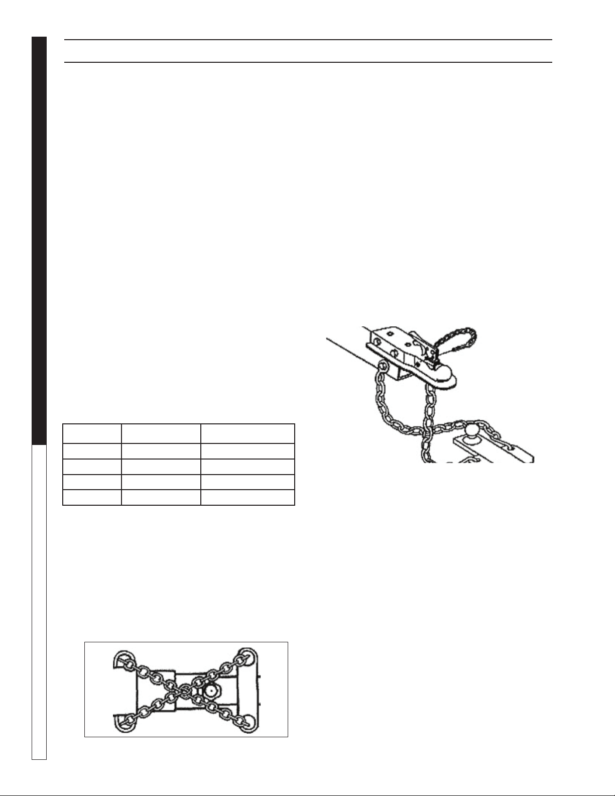
Trailer Ball & Couplers
WARNING: Failure to properly engage the hitch ball in
the coupler ball socket and securely lock the coupler
latch mechanism can cause the trailer to become
detached from the tow vehicle while traveling, which
may cause serious injury or property damage.
Ball diameter for which rating (GVWR) shall not exceed
the gross trailer weight marked on the trailer coupler.
The hitch balls have the rated load they are capable of
towing stamped Into the top of the ball.
Make sure the ball that you use to tow your trailer has the
same capacity rating as the coupler.
Do not use a different size ball than the size the coupler
is designed to use.
Class Coupler Ball Diameter
II 3,500# GVWR 2”
III 5,000# GVWR 2”
IV 8,000# GVWR 2 5/16"
Kärcher TRS-SSG • Operators • 9.801-330.0-K
5
PRESSURE WASHER
OPERATOR’S MAN U AL
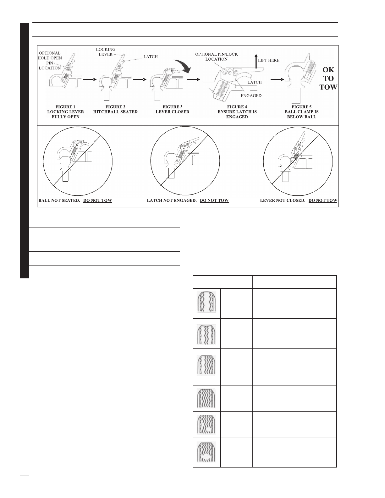
Operation
To Couple:
1) Block trailer wheels.
2) Align hitch ball beneath coupler.
3) Open coupler locking lever. While holding locking lever
open, lower the coupler over the hitch ball until ball is fully
seated into the ball pocket.
4) If locking lever is pinned open, remove pin. Move
locking lever to the closed position. Check that the latch is
engaged by lifting up on back of locking lever. Also, check
that the hitch ball is fully seated and ball clamp is below
the ball. If the ball is not seated with lever in the closed
position and latch engaged, DO NOT TOW.
Repeat the above steps.
5) OPTIONAL: Place a 5/16” pin or lock in hole shown
To Uncouple:
1) Block trailer wheels.
2) Open locking lever. While holding locking lever fully
open, raise trailer off of hitch ball.
NOTE: A 5/16” diameter pin can be used to hold the
locking lever open.
Hitch Coupler Troubleshooting
If the coupler becomes damaged it must be repaired
or replaced before towing. When the coupler is placed
on the ball, the latch should close fi rmly. Keep the latch
mechanism lightly oiled and clean. Items to check for are
as follows:
1. Latch does not grasp ball securely:
• Check the ball size. Make sure the ball and
coupler are the same size.
2. Latch does not snap into full latch position:
• Check adjustment. Latch mechanism may be
too tight.
• Check to see that the coupler housing has not
been damaged, keeping the ball hitch from fi tting
completely into the housing as designed.
3. Keep the tongue blocked up when not in use so the
coupler and mechanism are not in the ground being
exposed to dirt and moisture.
4. Apply a small amount of an automotive grease to the
ball before hitching coupler to prevent wear of the two
parts during towing.
5. Make sure the latch safety pin is in position before
towing.
Coupler & Ball Engagement
If the coupler and towing ball resist attempts to make
engagement, do not force latch assembly. Instead, check
the ball diameter to verify that it conforms to Society of
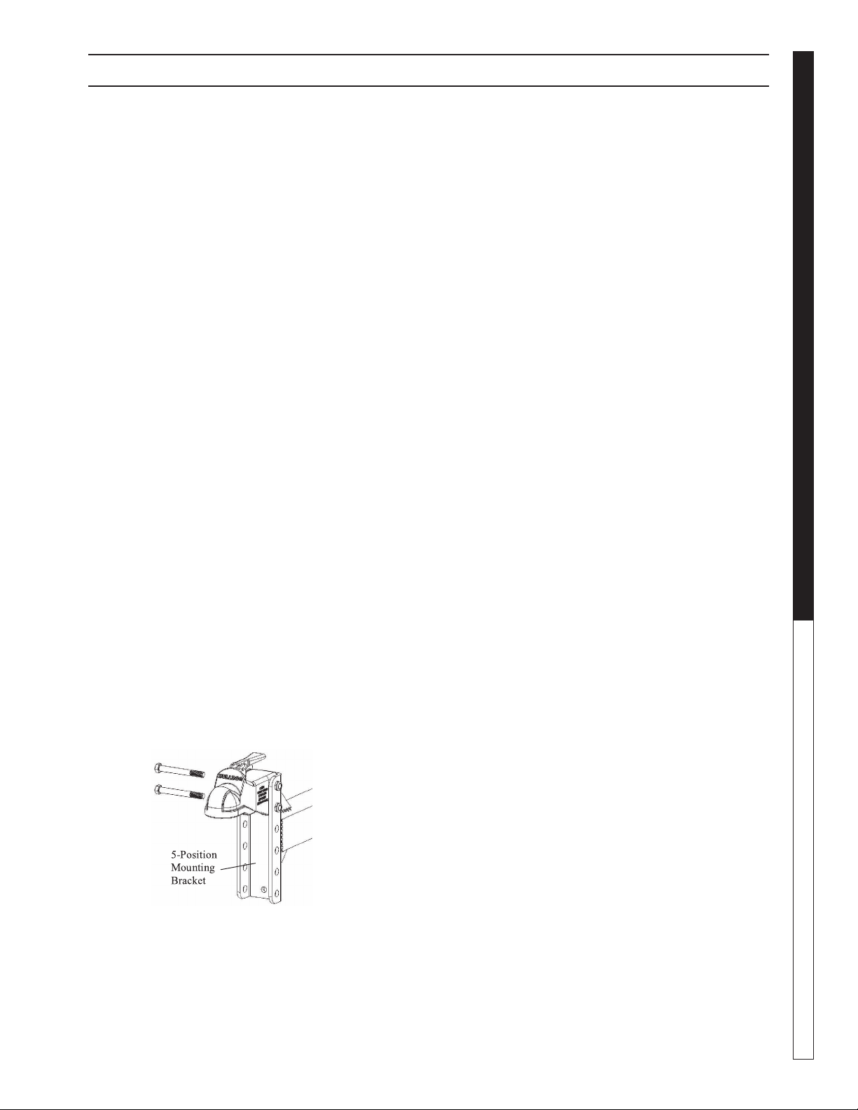
Before Towing:
Check mounting bracket hardware for wear and proper
tightness. Replace bent, broken, or worn hardware.
Tighten hardware to 75-94 ft. lbs. Use only the hardware
provided with the Trailer. If replacement hardware is
needed, order replacement kit 8.924-356.0.
Make sure that the trailer safety chains are properly
connected to the towing vehicle and trailer according to
SAE J684. See Safety Chain information in your manual.
Make sure that all trailer lighting is hooked up and working
properly.
Warning: Failure to follow all installation
instructions could result in coupler failure.
Variable Height Bracket:
Coupler operation must not be impaired in any way. Do
not use if coupler operation is impaired.
Bolting Instructions:
Align holes in coupler and mounting bracket. NOTE:
Coupler must be secured to mounting bracket using
two sets of holes in the mounting bracket. Insert two (2)
5/8”x4.5”, grade 5 bolts through desired mounting bracket
holes and coupler. For each bolt, Place one (1) washer
at the bolt head side and another at the bolt thread side
before assembling the nuts. Tighten lock nuts to 90-96
ft. lbs. After installation, ensure coupler operation is not
impaired in any way. Do not use if coupler operation is
impaired. The hardware provided with the trailer has a
self-lubricating coating which is taken into account for
the tightening torque above, and is lower than standard
hardware and also is more consistent with re-torque
specifi cations to fi rst-torque than standard hardware.
Order replacements with the 8.924-356.0 replacement
kit, or consult your hardware vendor for applicable, higher,
torques for the application.
Maintenance
Keep ball pocket and mechanism clean. The following
procedures should be performed at least annually:
• Check set screw torque Grease ball pocket
• Oil pivot points with SAE 30 wt. motor oil
• Inspect retaining pin and replace if necessary
IMPORTANT TRAILER SAFETY INFORMATION
Kärcher TRS-SSG • Operators • 9.801-330.0-K
OPERATOR’S MANUAL
PRESSURE WASHER
6
IMPORTANT TRAILER SAFETY INFORMATION
Automotive Engineers (SAE) specifi cations. Standard
two-inch diameter ball should be within the limits of
2.000-inches to 1.970-inches. Balls larger than 2.000-
inches will not readily fi t the coupler. A two-piece coupler
ball is not recommended.
If the coupler becomes damaged it must be repaired
or replaced before towing. When the coupler is placed
on the ball, the latch should close fi rmly. Keep the latch
mechanism lightly oiled and clean.
Improper engagement of the coupler and ball can cause
damage if the vehicles separate in transit, thus, caution
must be exercised to insure a secure hook-up. Lower the
coupler onto the ball with the coupler latch in the vertical
position. Continue to lower the trailer tongue until the jack
clears the ground, then fl ip the coupler latch to its locked
(horizontal) position. At this point visually observe that
the ball is fully engaged in the ball hitch. An even better
check to make sure the two are fully engaged is to raise
the tongue of the trailer again using the jack. Raise until
the ball hitch connection starts to raise the rear of the
tow vehicle. If the connection was not properly made, the
ball and socket will separate as the tongue of the trailer
is raised.
Safety Chains
Listed in the chart below are the different class sizes
of safety chains and the rated load each chain must
be capable of withstanding. Your trailer is equipped
with safety chains that meet the requirements of D.O.T
Regulation 393.70.
TRAILER CLASS
TRAILER WEIGHT
GVWR IN LBS.
MINIMUM BRAKING
STRENGTH IN LBS.
I to 2,000 2,000
II 2,000 to 3,500 3,500
III 3,500 to 5,000 5,000
IV 5,000 to 7,000 7,600
WARNING: Failure to properly attach safety chains
between the trailer and tow vehicle can result in a
runaway trailer.
WARNING: To avoid accidents, before trailering:
• Hitch only to ball size marked on coupling.
• Ball clamp must capture ball and lever or hand
wheel is fully clamped.
• Cross safety chains under coupling.
• Allow only enough slack for turns.
Bottom View
The safety chains on your trailer are an added insurance
that it will not become detached from the tow vehicle. All
safety chains are provided with an added clasp to keep
them from becoming accidentally detached from the tow
vehicle. Your trailer hitch on the tow vehicle should
have two attaching holes or rings for attaching the safety
chains, preferably one on each side of the ball hitch.
Crisscross the chains under the tongue, the chain on the
left side of the trailer tongue attached to the right side
of the ball hitch, the chain on the right side of the trailer
tongue attached to the left side of the ball hitch.
This prevents the trailer tongue from dropping to the road
should the coupler or ball hitch fail. The chains should
be rigged as tight as possible with just enough slack to
allow tight turns to be made. This can be accomplished by
twisting the chain hook in a clockwise or counterclockwise
direction thus twisting the link spacing and making the
chain shorter. Also by keeping your chains as short as
possible you prevent them from dragging on the road
and wearing the chain links. If for any reason you fi nd
it necessary to replace a safety chain, use only original
equipment.
Load-Carrying Capacity
Located on the front left-hand side of the frame, (either
the inside or the outside) is the VIN (Vehicle Identifi cation
Number) tag. It will show the GVWR (Gross Vehicle Weight
Rating) which is the maximum load that can be applied
to the tires on the trailer. The GVWR and the carrying
capacity of the trailer are based on the tire size installed
on the trailer.
The GVWR is the maximum carrying capacity of the trailer
with its respective tires. It may not necessarily equal the
total GVWR of the trailer less the empty weight of the
trailer because there may be another controlling factor
such as frame strength that reduces the carrying capacity
to what is listed on the VIN tag.
The tire label will list the tire size that was installed on
the trailer as original equipment when it was sold to you,
the consumer. It also lists the maximum carrying capacity
of the trailer.
Kärcher TRS-SSG • Operators • 9.801-330.0-K
7
PRESSURE WASHER
OPERATOR’S MAN U AL
IMPORTANT: The total weight of the load must never
exceed the weight of cargo listed on the tire label
and/or the maximum load carrying capacity listed
on the VIN tag on your trailer. The GVWR (Gross
Vehicle Weight Rating) listed is the maximum total
weight of the trailer with accessories and all cargo
allowable to be carried on the tires that are installed
on the trailer.
WARNING: Fishtailing caused from improper tongue
weight on the tow vehicle hitch ball can cause loss
of control of the tow vehicle and resulting serious
injury or property damage.
CAUTION: The maximum load applied to the trailer
must never exceed the carrying capacity of the
trailer as stated on the VIN label and/or the tire
placard. Doing so may cause failure of one or more
component parts of the trailer causing potential
damage to the trailer and/ or a potential accident.
All concentrated loads must be spread over as large
an area as possible to eliminate potential damage
to the decking.
Shown below is an example of the tire label that is placed
on your trailer showing the items just discussed above.
Once you have familiarized yourself with the information
supplied on the ex ample tire label and VIN tag, check
the tire size and capacity of your trailer as shown on
the VIN tag on your trailer.
Proper Weight Distribution & Tongue
Weight
Ensuring that your trailer has the proper GVWR is
very important. Once that has been established and
you have the load on the trailer it is equally important
that you have proper weight distribution.
Tongue Weight
The tongue weight on your trailer is 10%-15% of
the total weight of the trailer and all the cargo that it
is carrying. This is the amount of weight that is then
transferred to the tow vehicle through the ball hitch.
Example: The total weight of the trailer with load is
2500 pounds. The tongue weight should not be less
than 250 pounds (10%).
Too light of tongue weight can cause the trailer to
“fi shtail” (sway Weight Rating) as you travel down the
highway. This creates excessive strains on the tow
vehicle, hitch and on the trailer itself. It can very easily
lead to an accident.
To adjust for too light of a tongue weight the load must
be shifted for ward with respect to the axle. This will
increase the weight that is transferred to the tongue.
Adjustments should be made until the tongue weight
falls within 10% -15% recommended range. Likewise,
if you have too much tongue weight adjust the weight
backwards with respect to the axle until the tongue
weight falls in the recommended range
Tow vehicles vary on how much tongue weight they
can support for proper towing.
Tire Pressure
Proper air pressure for your tires is printed on the
sidewall. Check pressure while tires are cold. Do not
raise or lower pressure to meet load. Pressure other
than recommended pressure will lead to excessive tire
wear or tire failure. Balancing recommended.
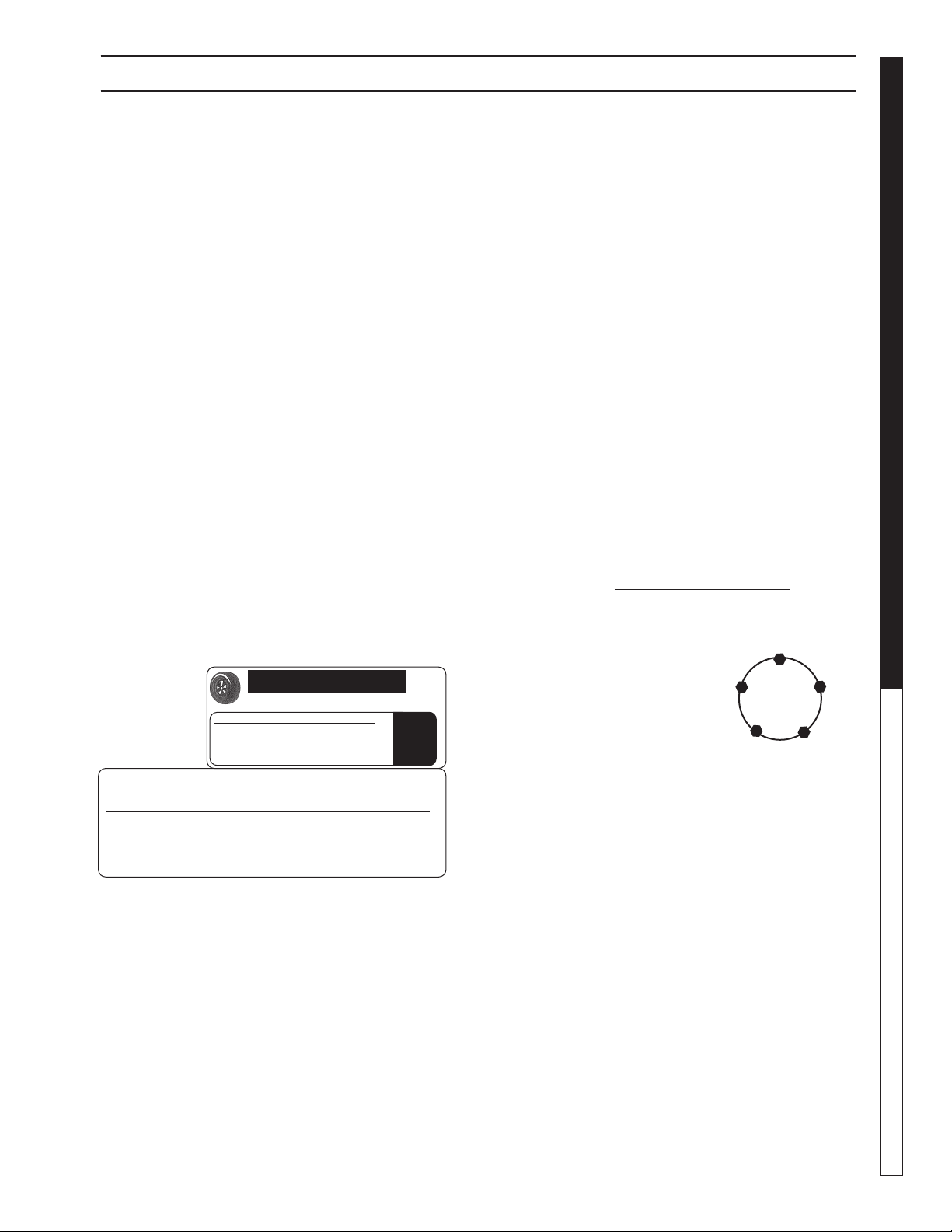
Wheels
Check wheels for hole elongation
or “out of round”. This condition
can be caused by lug nuts not be-
ing tight or being too tight. Trailer
wheels can be damaged by chuck
holes or curb jumping. You may
not be aware of the road shock to
the wheels without periodic checks. Replace any wheel
that is bent. Replace any wheel if you see elongation
of the bolt holes.
Wheel Lugs
Wheel lug nuts must be tightened with a torque wrench.
Refer to the chart below for proper torque.
1. Start all bolts or nuts by hand to prevent cross
threading.
2. Tighten bolts or nuts following sequence at right.
3. The tightening of the fasteners should be done in
stages. Following the recommended sequence,
tighten fasteners per wheel torque chart below.
4. Wheel nuts/bolts should be torqued before fi rst
road use and after each wheel removal. Check and
re-torque after the fi rst 10 miles, 25 miles and again
at 50 miles. Check periodically thereafter.
WHAT TO CHECK AND HOW TO CHECK
1
2
34
5
WHAT TO CHECK AND HOW TO CHECK
TIRE AND LOADING INFORMATION
RENSEIGNEMENTS SUR LES PNEUS ET LE CHARGEMENT
The weight of cargo should never exceed
764 kg or 1685 lbs
TIRE SIZE COLD TIRE PRESS.
REAR ST205 75 D15 C 345 KPA (50 MAX PSI)
INTER NONE/AUCUN
FRONT NONE
SPARE NONE
SEE OWNER’S
MANUAL FOR
ADDITIONAL
INFORMATION
VOIR LE MANUAL
DE L’USAGER
POUR PLUS DE
RENSEIGNEMENTS
MANUFACTURED BY: KARCHER NORTH AMERICA INC. DATE OF MFG.:01/2016
GAWR (EACH AXLE)
V.I.N..: TYPE : TRAILER
TRS-2500-SSG
WITH TIRES RIMS AT COLD
1134 KG (2500 LB) ST205 75 D15 C 15 X 5.5 J 345 KPA (50 PSI) SINGLE
THIS VEHICLE CONFORMS TO ALL APPLICABLE U.S. FEDERAL MOTOR VEHICLE SAFETY STANDARDS
IN EFFECT ON THE DATE OF MANUFACTURE SHOWN ABOVE.
1L9FA1013GC041666
Kärcher TRS-SSG • Operators • 9.801-330.0-K
OPERATOR’S MANUAL
PRESSURE WASHER
8
WEAR PATTERN CAUSE ACTIONACTION
Center
Wear
Over
Infl ation
Adjust pressure
to particular
load per tire
catalog.
Edge
Wear
Under
Infl ation
Adjust pressure
to particular
load per tire
catalog.
Side Wear
Loss of
camber or
overloading
Make sure load
doesn't exceed
axle rating.
Align at
alignment shop.
Toe Wear
Incorrect
toe-in
Align at
alignment shop.
Cupping
Out of
balance
Check bearing
adjustment and
balance tires.
Flat
Spots
Wheel
lockup & tire
skidding
Avoid sudden
stops when
possible and
adjust brakes.
WHEEL
SIZE
TORQUE SEQUENCE
1st Stage 2nd Stage 3rd Stage
15" 20 - 25 50 - 60 80-90
Wheel Torque Requirements
Ball Coupler Hitches
Coupler assembly includes a latch lever and latch
lever safety pin or hitch pin. Be sure the latch lever is
locked and the pin properly secured before moving
your trailer. The pin can be engaged fully only if ball
is properly seated in the coupler.
Tires
Before mounting tires onto wheels make certain that
the rim size and contour is approved for the tire as
shown in the Tire and Rim Association Yearbook or
the tire manufacturer’s catalog. Also make sure the
tire will carry the rated load. If the load is not equal
on all tires due to trailer weight distribution, use the
tire rated for the heaviest wheel position.
NOTE: The capacity rating molded into the sidewall of
the tire is not always the proper rating for the tire if used
in a trailer application. Use the following guideline:
1. LT and ST tires: use the capacity rating molded
into the tire.
2. Passenger Car Tires: Use the capacity rating
molded into the tire sidewall divided by 1.10.
Use tire mounting procedures as outlined by the
Rubber Manufacturer’s Association or the tire manu-
facturers.
WHAT TO CHECK AND HOW TO CHECK
NOTE: Tire wear should be checked frequently
because once a wear pattern becomes fi rmly
established in a tire it is diffi cult to stop, even
if the underlying cause is corrected.
Kärcher TRS-SSG • Operators • 9.801-330.0-K
9
PRESSURE WASHER
OPERATOR’S MAN U AL
WHAT TO CHECK AND HOW TO CHECK
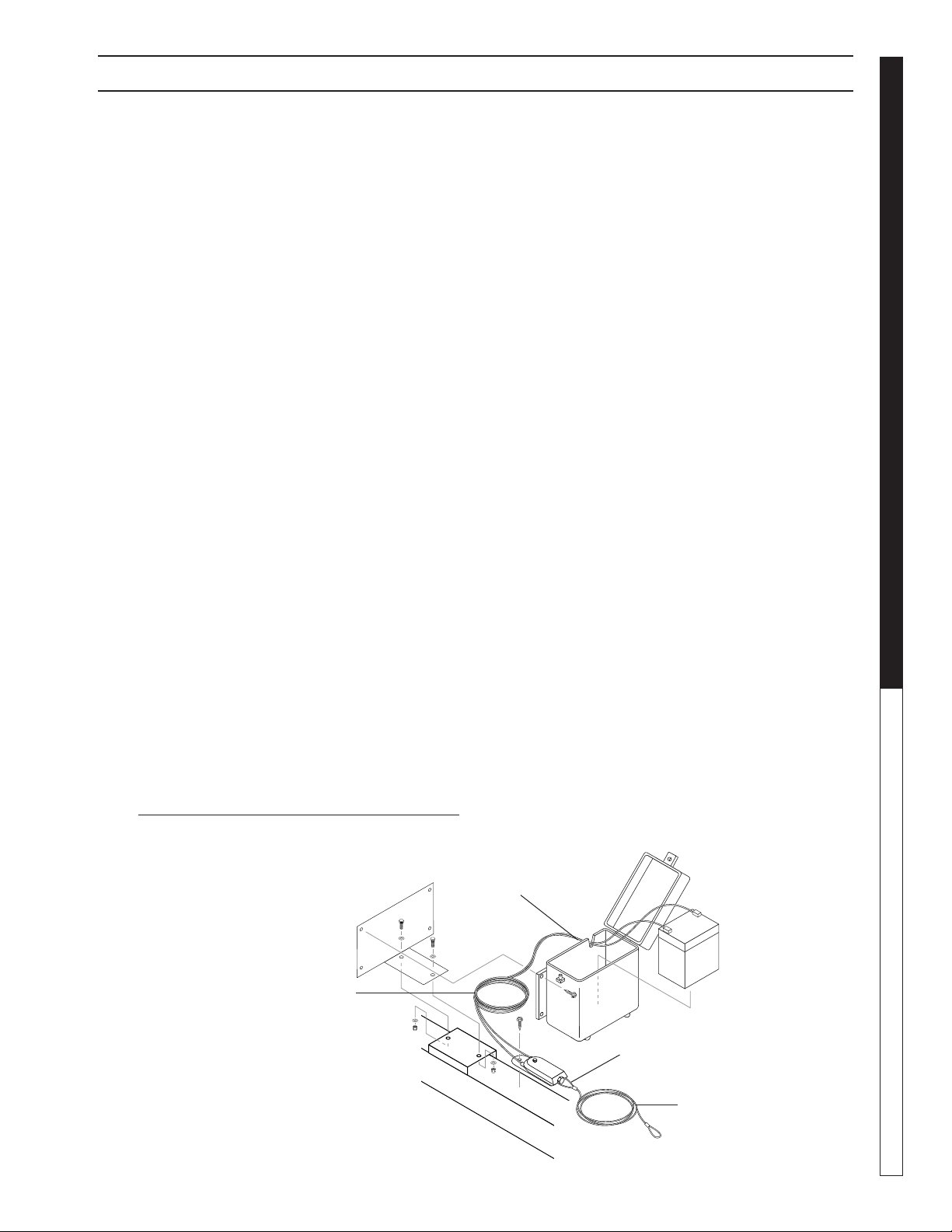
Breakaway Switch &
D.O.T. Wet Cell Battery
After hitching to the tow vehicle, pull the safety
pin on the breakaway switch. Check to see if
system is operational. Push safety pin back in
to its original position.
Check battery fl uid level every 60-90 days. Re-
move cover. There are two fi ll caps. Refi ll with
distilled water only.
Breakaway Switch
Mounted on an A-Frame
Attach breakaway switch cable securely in a
straight line to the tow vehicle. Locate at-
tachments so little “slack” is left in the cable,
but enough slack to allow for turning without
disengaging the pin. The cable will activate
brakes the instant a trailer becomes disen-
gaged. Brake adjustment is critical to stopping
a disengaged trailer.
Check Breakaway System
& Brakes Before Each Trip
1. Disconnect 12V plug from tow vehicle.
2. Pull breakaway pin.
3. While pin is pulled, move tow vehicle forward. Brake
should be on and wheels locked.
4. Replace pin and secure to tow vehicle. Do not loop
over hitch ball.
5. Plug 12V connector into tow vehicle receptacle.
6. Test brakes with brake controller.
NOTE: When disconnecting trailer from tow ve-
hicle, make sure to replace safety pin.
Breakaway Battery
(Two fi ll caps
underneath cover)
Power
Cable
Breakaway
Pin
Cable to
Vehicle
Breakaway Battery on A-Frame
Brakes
Your trailer is equipped with electric brakes.
Complete service and repair information for the
electric brakes is found in the Axle Break Ser-
vice Manual that is furnished with your trailer,
Note: It is important to strictly adhere to the axle
break instructions for brake service and re-
pair. In this way, you are protecting the validity
of all applicable warranties
.
Burnishing the Brakes
Brakes on a new trailer may tend to “grab” or pul-
sate. This is normal. To correct the situation,
pull the trailer with the trailer brake control
slightly engaged a short distance (about 1000
ft or until trailer does not grab or pull to one
side anymore). This action smooths down the
brake bands
.
Note: Do not lock up the wheels.

Kärcher TRS-SSG • Operators • 9.801-330.0-K
OPERATOR’S MANUAL
PRESSURE WASHER
10
Brake Adjustment
Brakes should be adjusted (1) after the fi rst 200
miles of operation after the brake shoes and
drums have “seated”, (2) at 3000 mile intervals
and (3) as use and performance require. The
brakes should be adjusted in the following
manner:
1. Jack up trailer and secure on adequate capacity jack
stands. Check that wheel and drum rotate freely.
2. Remove adjusting hole cover from adjusting slot on
bottom of brake backing plate.
3. With screwdriver or standard adjusting tool, rotate
the starwheel of the adjuster assembly to expand
the brake shoes. Adjust the brake shoes out until
the pressure of the linings against the drum makes
the wheel very diffi cult to turn.
NOTE: With drop spindle axles, a modifi ed adjusting
tool with about an 80 degree angle should be used.
4. Then rotate starwheel in opposite direction until
wheel turns freely with slight lining drag.
5. Replace the adjusting hole cover and lower wheel
to ground.
6. Repeat above procedure on all brakes.
CAUTION: Never crawl under your
trailer unless it is resting on properly
placed jack stands.
Do not lift or place supports on any part of
the suspension system.
Brake Cleaning &
Inspection
Your trailer brakes must be inspected and ser-
viced at yearly intervals or more often as use
and performance require. Magnets and shoes
must be changed when they become worn or
scored thereby preventing inadequate vehicle
braking.
Clean the backing plate, magnet arm, magnet and
brake shoes. Make certain that all the
parts removed are replaced in the same
brake and drum assembly. Inspect the
magnet arm for any loose or worn parts.
Check shoe return springs, hold down springs
and adjuster springs for stretch or deformation
and replace if required.
CAUTION: Asbestos Dust Hazard. Since
some brake shoe friction materials con-
tain asbestos, certain
precautions need to be taken when ser-
vicing brakes:
1. Avoid creating or breathing dust.
2. Avoid machining, fi ling or grinding the brake linings.
3. Do not use compressed air or dry brushing for clean-
ing. (Dust can be removed with a damp brush).
TRAILER STORAGE
Preparation
If your trailer is to be stored for an extended period
of time or over the winter, it is important that
the trailer be prepared properly.
1. Remove the emergency breakaway battery and store
inside, out of the weather. Charge the battery at least
every 90 days.
2. Jack up the trailer and place jack stands under trailer
frame so that the weight will be off the tires. Never
jack up or place jack stands on the axle tube or on
the equalizers.
3. Lubricate mechanical moving parts that are exposed
to weather, such as the hitch and suspension parts.
NOTE: On oil lubricated hubs the upper part of the
roller bearings are not immersed in oil and are
subject to potential corrosion. For maximum
bearing life it is recommended that you revolve
your wheels periodically (every 2-3 weeks) dur-
ing periods of prolonged storage.
After Prolonged Storage — Inspection Procedures
Before removing trailer from jack stands:
1. Remove all wheels and hubs or brake drums. Note
which spindle and brake that the drum was removed
from so that it can be reinstalled in the same location.
2. Inspect suspension for wear.
3. Check tightness of hanger bolt, shackle bolt and
U-bolt nuts per recommended torque values.
4. Check brake linings, brake drums and armature faces
for excessive wear or scoring.
5. Check brake magnets with an ohmmeter. The
magnets should check 3.2 ohms. If shorted or worn
excessively, replace.
6. Lubricate all brake moving parts using a high temper-
ature brake lubricant. (LUBRIPLATE or equivalent).
CAUTION: Do not get grease or oil on
brake linings or magnet face.
7. Remove any rust from braking surface and armature
surface of drums with fi ne emery paper or crocus
cloth. Protect bearings from contamination while so
doing.
8. Inspect oil or grease seals for wear or nicks. Replace
if necessary.
9. Lubricate hub bearings. Refer to procedure in manual.
10. Reinstall hubs and adjust bearing per instructions in
manual.
WHAT TO CHECK AND HOW TO CHECK
Kärcher TRS-SSG • Operators • 9.801-330.0-K
11
PRESSURE WASHER
OPERATOR’S MAN U AL
IMPORTANT PRESSURE WASHER SAFETY INFORMATION
Thank you for purchasing a Landa Pressure
Washer. We reserve the right to make changes
at any time without incurring any obligation.
Owner/User Responsibility:
The owner and/or user must have an understand-
ing of the manufacturer’s operating instructions and
warnings before using this pressure washer. Warning
information should be emphasized and understood.
If the operator is not fl uent in English, the manufac-
turer’s instructions and warnings shall be read to and
discussed with the operator in the operator’s native
language by the purchaser/owner, making sure that
the operator comprehends its contents.
Owner and/or user must study and maintain for future
reference the manufacturers’ instructions.
The operator must know how to stop the machine
quickly and understand the operation of all controls.
Never permit anyone to operate the engine without
proper instructions.
SAVE THESE INSTRUCTIONS
This manual should be considered a permanent
part of the machine and should remain with it if
machine is resold.
When ordering parts, specify model and serial
number. Use only identical replacement parts.
This machine is to be used only by trained
operators.
IMPORTANT SAFETY
INFORMATION
READ OPERATOR’S
MANUAL THOROUGHLY
PRIOR TO USE.
WARNING: To reduce the risk
of injury, read operating
instructions carefully before
using.
1. Read the owner's manual
thoroughly. Failure to follow
instructions could cause
malfunction of the machine
and result in death, serious
bodily injury and/or property
damage.
2. Know how to stop the machine and bleed pres-
sure quickly. Be thoroughly familiar with the
controls.
3. Stay alert — watch what you are doing.
DANGER: Keep wand, hose, and
water spray away from electric
wiring or fatal electric shock
may result.
4. Follow engine fuel recom-
mendation in the engine manual
provided
.
RISK OF EXPLOSION:
OPERATE ONLY WHERE
OPEN FLAME OR TORCH
IS PERMITTED
WARNING
WARNING: Flammable liquids
can create fumes which can
ignite, causing property dam-
age or severe injury.
WARNING: Risk of explosion —
Operate only where open fl ame
or torch is permitted.
5. Use only kerosene, No. 1 home heating fuel, or
diesel for the hot water burner. If diesel is used,
add a soot remover to every tankful.
WARNING: Gasoline is highly flammable and
explosive. You can be seriously injured when
refueling.
• Stop engine and keep heat sparks and fl ame
away.
• Refuel only outdoors.
• Wipe up spills immediately.
RISK OF FIRE.
DO NOT ADD FUEL
WHEN OPERATING
MACHINE.
WARNING
WARNING: Risk of fi re — Do
not add fuel when the product
is operating or still hot.
WARNING: Do not use gaso-
line crankcase draining or oil
containing gasoline, solvents
or alcohol. Doing so will result
in fi re and/or explosion.
6. Operate only in locations where combustible dusts
and fl ammable gases or vapors are not present.
Do not store or use gasoline near this machine.
7. Do not allow acids, caustic or abrasive fl uids to
pass through the pump.
8. Never run pump dry or leave spray gun closed
longer than 1-2 minutes.
9. Keep operating area clear of all persons.
KEEP WATER
SPRAY AWAY
DANGER
Kärcher TRS-SSG • Operators • 9.801-330.0-K
OPERATOR’S MANUAL
PRESSURE WASHER
12
WARNING: High pressure de-
veloped by these machines will
cause personal injury or equip-
ment damage. Keep clear of
nozzle. Use caution when oper-
ating. Do not direct discharge
stream at people, or severe
injury or death will result.
WARNING: Protect machine
from freezing.
14. To keep machine in best
operating conditions, it is
important you protect machine
from freezing. Failure to protect
machine from freezing could
cause malfunction of the ma-
chine and result in death, seri-
ous bodily injury, and/or property
damage. Follow storage instructions specifi ed in
this manual.
15. Inlet water must be clean fresh water and no hotter
then 90°F.
WARNING
RISK OF
ASPHYXIATION: USE
THIS PRODUCT ONLY
IN A WELL
VENTILATED AREA.
WARNING: Risk of asphyxiation.
Use this product only in a well
ventilated area.
16. Avoid operating machines
in small areas or near ex-
haust fans. Adequate ox-
ygen is needed for com-
bustion or dangerous car-
bon monoxide will result.
17. Manufacturer will not be liable for any changes
made to our standard machines or any compo-
nents not purchased from us.
18. The best insurance against an accident is precau-
tion and knowledge of the machine.
WARNING
RISK OF INJURY
FROM FALLS WHEN
USING LADDER.
WARNING: Be extremely careful
when using a ladder, scaffolding
or any other relatively unstable
location. The cleaning area
should have adequate slopes
and drainage to reduce the pos-
sibility of a fall due to slippery
surfaces.
19. Do not overreach or stand on unstable support.
Keep good footing and balance at all times.
IMPORTANT PRESSURE WASHER SAFETY INFORMATION
WARNING
USE PROTECTIVE
EYE WEAR
AND CLOTHING
WHEN OPERATING
THIS EQUIPMENT.
WARNING: High pressure spray
can cause paint chips or other
particles to become airborne
and fl y at high speeds. To avoid
personal injury, eye, hand and
foot safety devices must be
worn.
10. Eye, hand, ear, and foot
protection must be worn
when using this equipment.
WARNING
EAR PROTECTION
MUST BE WORN
WARNING: This machine ex-
ceeds 85 dB. Appropriate ear
protection must be worn.
WARNING
HOT DISCHARGE FLUID:
DO NOT TOUCH OR
DIRECT DISCHARGE
STREAM AT PERSONS.
WARNING: Hot discharge fl uid.
Do not touch or direct
discharge stream at persons.
WARNING: This machine pro-
duces hot water and must have
insulated components attached
to protect the operator.
WARNING
RISK OF INJURY:
HOT SURFACES
CAN CAUSE BURNS
WARNING: Risk of injury. Hot
surfaces can cause burns. Use
only designated gripping areas
of spray gun and wand. Do not
place hands or feet on non-in-
sulated areas of the pressure
washer.
11. To reduce the risk of injury, close supervision is
necessary when a machine is used near children.
Do not allow children to operate the pressure
washer. This machine must be attended during
operation.
TRIGGER GUN KICKS
BACK - HOLD WITH
BOTH HANDS
WARNING
WARNING: Grip cleaning wand
securely with both hands be-
fore starting. Failure to do this
could result in injury from a
whipping wand.
12. Never make adjustments
on machine while in
operation.
13. Be certain all quick cou-
pler fi ttings are secured be-
fore using pressure washer.
RISK OF INJECTION
OR SEVERE INJURY
TO PERSONS. KEEP
CLEAR OF NOZZLE.
WARNING
WARNING
PROTECT FROM
FREEZING

Kärcher TRS-SSG • Operators • 9.801-330.0-K
13
PRESSURE WASHER
OPERATOR’S MAN U AL
IMPORTANT PRESSURE WASHER SAFETY INFORMATION
20. Do not operate this machine when fatigued or under
the infl uence of alcohol, prescription medications,
or drugs.
21. Before disconnecting discharge hose from water
outlet, turn burner off and open spray gun to allow
water to cool below 100° before stopping the ma-
chine. Then open the spray gun to relieve pressure.
Failure to properly cool down or maintain the heat-
ing coil may result in a steam explosion.
Follow the maintenance instructions
specifi ed in the manual.
REPORTING SAFETY
DEFECTS
If you believe that your trailer has a defect which could cause
a crash or could cause injury or death, you should immedi-
ately inform the National Highway Traffi c Safety Administra-
tion (NHTSA) in addition to notifying Landa.
If NHTSA receives similar complaints, it may open an inves-
tigation, and if it fi nds that a safety defect exists in a group of
trailers, it may order a recall and remedy campaign. However,
NHTSA cannot become involved in individual problems be-
tween you, your dealer or Landa.
To contact NHTSA, you may either call the Auto Safety
Hotline toll-free at 1-888-327-4236 (or 202-366-4000 in
Washington, DC area) (TTY: 1-800-424-9153) or write to:
NHTSA
1200 New Jersey Avenue, SE
West building
Washington, DC 20590
http://www.safercar.gov
http://www.nhtsa.gov/nhtsa-spmextnljsp/email_nhtsa.jsp
You can also obtain other information about motor vehicle
safety from the Hotline
Kärcher TRS-SSG • Operators • 9.801-330.0-K
OPERATOR’S MANUAL
PRESSURE WASHER
14
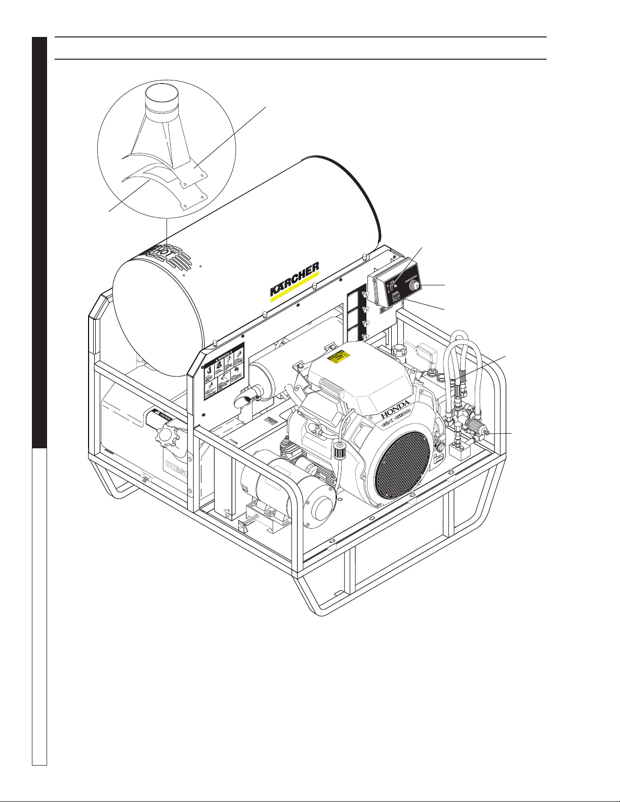
98013300-2
PRESSURE WASHER COMPONENT IDENTIFICATION
Pump — Delivers a specifi c gpm to the high pressure
nozzle which develops pressure.
Spray Gun — Controls the application of water and
de ter gent onto cleaning surface with trigger device.
In cludes safe ty latch.
Unloader Valve— Safety device which allows
pres sure to be released when spray gun is closed.
High Pressure Hose — Connect one end to wa-
ter pump dis charge nipple and the other end to
spray gun.
Adjustable Thermostat — Safety control which
pre vents temperatures from going above adjustable
set ting.
NOTE: If fl ue adapter is installed, the burner as sem bly
air adjustment must be adjusted.
Flue Adapter
Optional 8.717-745.0
Insulation Gasket
Optional 8.717-425.0
Burner
Switch
Hour Meter
Adjustable
Thermostat
Unloader
Valve
Pump
Kärcher TRS-SSG • Operators • 9.801-330.0-K
15
PRESSURE WASHER
OPERATOR’S MAN U AL
98013300-3
PRESSURE WASHER ASSEMBLY INSTRUCTIONS
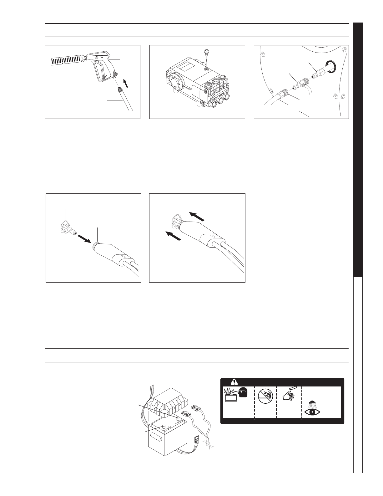
STEP 1: Attach the high pres sure
hose to the spray gun by threading
onto spray gun inlet.
STEP 2: Remove shipping cap
and install oil dipstick (Depending
on type of shipping, dipstick may
already be installed). Check pump
oil lev el by us ing dip stick or observe
oil level in oil win dow (if equipped).
Use SAE 10W-40 non detergent oil.
Spray
Gun
High Pressure
Hose
98013300-5
BATTERY INSTALLATION
Due to Federal Reg u la tions con cern ing ship ment of
cor ro sive chem i cals, batteries are gel fi lled.
Red Ca ble is at-
tached to bat tery
(+) pos i tive ter mi-
nal, black cable
is con nect ed to
bat tery (-) neg a tive
terminal.
SHIELD
EYES
EXPLOSIVE
GASES
CAN CAUSE
BLINDNESS OR INJURY
NO
SPARKS
FLAMES
SMOKING
SULFURIC
ACID
CAN CAUSE
BLINDNESS OR
SEVERE BURNS
FLUSH EYES
IMMEDIATELY
WITH WATER
GET
MEDICAL
HELP
FAST
KEEP OUT OF THE REACH OF CHILDREN. DO NOT TIP. KEEP VENT CAPS TIGHT AND LEVEL.
DANGER
/
POISON
98013300-27
Black - Negative
Terminal
Red + Positive
Terminal
STEP 5: Release the coupler collar
and push the nozzle until the collar
clicks. Pull the nozzle to make sure
it is seated properly.
98013300-26
Pressure
Nozzle
Pressure
Nozzle
STEP 4: Pull the spring-loaded col-
lar of the wand coupler collar back
to in sert your choice of pressure
noz zle.
CAUTION: Never replace
noz zles with out engaging the
safe ty latch on the spray gun
trig ger.
98013300-25
Wand Coupler
Collar
STEP 3: Connect high pressure
hose to discharge nipple by slid-
ing quick coupler collar back. (If
de ter gent is to be ap plied, insert
a de ter gent injector.) Insert quick
coupler onto dis charge nipple and
se cure by pushing quick coupler
collar for ward.
98013300-24
Detergent
Injector
(Option)
High
Pressure Hose
Discharge
Nipple
Coupler
Collar
Kärcher TRS-SSG • Operators • 9.801-330.0-K
OPERATOR’S MANUAL
PRESSURE WASHER
16
98013300-7
98013300-10
PRESSURE WASHER OPERATING INSTRUCTIONS
98013300-6
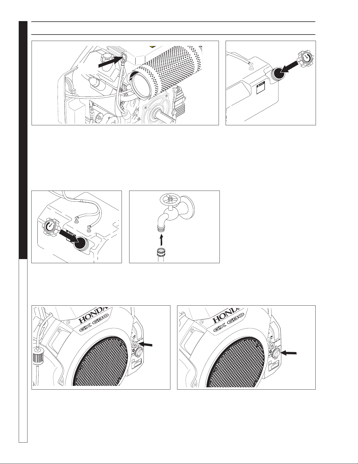
STEP 1: Check engine oil level. Oil level should be level to the fi ll mark-
ings on the dipstick. Be sure the ma chine is level when checking the oil
level. (Refer to the en gine's op er at ing manual included with machine.) We
rec om mend that the oil be changed after the fi rst 5 hours of use, then once
every 100 hours. NOTE: Im prop er oil levels will cause low oil sensor to
shut off engine. IM POR TANT! Do not run engine with high or low oil
levels as this will cause engine dam age.
STEP 4: Connect garden hose
to the cold water source and turn
wa ter on completely. Never use hot
wa ter. Allow water tank to fi ll before
ssssarting
STEP 2: Fill gas tank with un lead-
ed gasoline. Do not use leaded
gas o line.
STEP 5: Pull the choke lever out to the "Choke" po-
si tion (on a warm engine, leave the choke lever in the
run po si tion). Push the choke lever to the "Closed"
po si tion. To restart a warm engine, leave the choke
lever in the "Open" position.
Cold
Water
Source
Garden
Hose
Oil
Dipstick
98013300-29
Choke
Lever
STEP 6: Turn the engine key switch to "Start" po si tion.
98013300-11
On-Off
Switch
98013300-8
STEP 3: Fill diesel tank with stove
oil, kerosene or diesel fuel.
Diesel
Tank
Kärcher TRS-SSG • Operators • 9.801-330.0-K
17
PRESSURE WASHER
OPERATOR’S MAN U AL
98013300-13
98013300-9
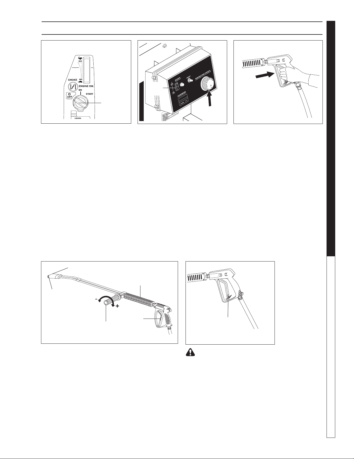
STEP 9: Before installing pressure
nozzle, trigger spray gun to elimi-
nate trapped pressure. Then run
machine, allowing water to flush
through the system until clear.
PRESSURE WASHER OPERATING INSTRUCTIONS
Thermostat
Burner
Switch
STEP 7: Turn the key to the START
position, and hold it there until the
engine starts. If the engine fails to
start within 5 seconds, release the
key, and wait at least 10 seconds
before op er at ing the starter again.
Using the electric starter for more
than 5 seconds at a time will
over heat the starter motor and
can dam age it.
When the engine starts, release the
key, allowing it to return to the ON
position. If the choke knob has been
pulled to the CLOSED position to
start the engine, grad u al ly push it
to the OPEN position as the engine
warms up.
98013300-12
ON
OFF
START
Engine
Switch
98013300-14
Safety
Latch
WARNING! Never replace noz -
zle without engaging the safe ty
latch on the spray gun trig ger.
STEP 8:Turn the burner switch
"ON". Turn thermostat dial to the
desired temperature setting.
98013300-28
Selection of high or low pressure is accompanied by
turn ing the han dle. NOTE: High pressure nozzle must
be in sert ed at end of wand to obtain high pressure. To
apply soap, read detergent instructions.
Variable Pressure
Control Handle
Trigger
Variable Pressure
Wand (VP)
High
Pressure
Nozzle
Brass Soap Nozzle

Kärcher TRS-SSG • Operators • 9.801-330.0-K
OPERATOR’S MANUAL
PRESSURE WASHER
18
WARNING: Some de ter gents
may be harm ful if in haled or
in gest ed, caus ing severe nau-
sea, faint ing or poi son ing. The
harm ful el e ments may cause
prop er ty dam age or severe
injury.
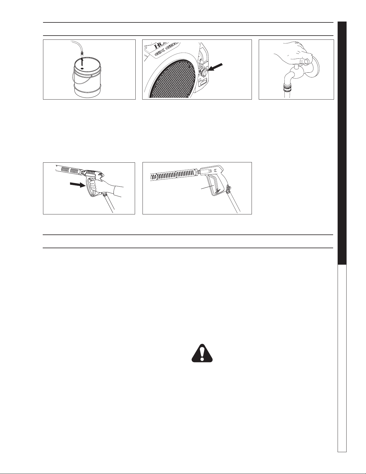
STEP 1: Use detergent de signed
spe cifi cal ly for pres sure washers.
House hold de ter gents could dam-
age the pump. Pre pare detergent
so lu tion as required by the man u fac-
tur er. Fill a container with pres sure
wash er de ter gent. Place the fi l ter
end of de ter gent suc tion tube into
the de ter gent con tain er.
STEP 2: Apply safety switch
to spray gun trigger. Secure
black nozzle into quick coupler.
NOTE: Detergent cannot be applied
using yellow nozzle.
STEP 3: With the engine run ning,
pull trig ger to op er ate ma chine. Liq uid de ter gent is
drawn into the ma chine and mixed with water. Apply
de ter gent to work area. Do not al low de ter gent to dry
on sur face.
IMPORTANT: You must fl ush the detergent from
your machine af ter each use by plac ing the suc tion
tube into a buck et of clean water and then run ning
the pres sure wash er for 1-2 min
utes.
THERMAL PUMP
PROTECTION
If you run the engine on your pres sure wash er for 3-5
min utes with out pressing the trig ger on the spray gun,
cir cu lat ing water in the pump can reach high tem-
per a tures. When the water reaches this tem per a ture,
the pump pro tec tor engages and cools the pump by
dis charg ing the warm water onto the ground. This
ther mal de vice pre vents internal dam age to the pump.
CLEANING TIPS
Pre-rinse clean ing surface with fresh water. Place de-
ter gent suc tion tube di rect ly into clean ing solution and
ap ply to sur face at low pressure (for best re sults, lim it
your work area to sec tions ap prox i mate ly 6 feet square
and always ap ply de ter gent from bottom to top). Allow
de ter gent to re main on sur face 1-3 min utes. Do not
al low de ter gent to dry on sur face. If sur face appears
to be dry ing, sim ply wet down sur face with fresh wa ter.
If need ed, use brush to re move stub born dirt. Rinse at
high pres sure from top to bot tom in an even sweep ing
mo tion keep ing the spray nozzle ap prox i mate ly 1 foot
from clean ing sur face. Use over lap ping strokes as you
clean and rinse any sur face. For best surface clean ing
action spray at a slight an gle.
Recommendations:
• Before cleaning any surface, an inconspicuous
area should be cleaned to test spray pattern and
dis tance for maximum cleaning results.
• If painted surfaces are peeling or chipping,
use ex treme caution as pressure washer may
re move the loose paint from the surface.
• Keep the spray nozzle a safe distance from
the sur face you plan to clean. High pressure
wash a small area, then check the surface for
damage. If no dam age is found, continue to
pressure wash ing.
CAUTION - Never use:
• Bleach, chlorine products and other corrosive
chem i cals
• Liquids containing solvents (i.e., paint thinner,
gas o line, oils)
• Tri-sodium phosphate products
• Ammonia products
• Acid-based products
These chemicals will harm the machine and will
dam age the surface being cleaned.
RINSING
It will take a few sec onds for the de ter gent to clear.
Apply safe ty latch to spray gun. Re move black soap
noz zle from the quick cou pler. Select and in stall the
de sired high pres sure noz zle. NOTE: You can also stop
de ter gent from fl ow ing by sim ply re mov ing de ter gent
si phon tube from bottle.
WARNING
DETERGENTS & GENERAL CLEANING TECHNIQUES
98013300-15
8013300-16
98013300-17
Kärcher TRS-SSG • Operators • 9.801-330.0-K
19
PRESSURE WASHER
OPERATOR’S MAN U AL
98013300-21
98013300-17
98013300-19
PRESSURE WASHER SHUT DOWN AND CLEAN-UP
STORAGE
CAUTION: Al ways store your pressure washer in a
lo ca tion where the temperature will not fall be low
32°F (0°C). The pump in this machine is sus cep ti ble
to permanent dam age if fro zen. FREEZE DAM AGE
IS NOT COV ERED BY WARRANTY.
1. Stop the pressure washer, squeeze spray gun
trig ger to release pressure.
2. Detach water supply hose and high pressure
hose.
3. Turn on the machine for a few seconds, until
re main ing water exits. Turn engine off im me di ate ly.
4. Drain the gas and oil from the engine.
5. Do not allow high pressure hose to become
kinked.
6. Store the machine and accessories in a room which
does not reach freezing temperatures.
CAUTION: Fail ure to follow the above di rec tions will
result in dam age to your pres sure washer.
When the pres sure washer is not being operated or is
be ing stored for more than one month, follow these
in struc tions:
1. Replenish engine oil to up per level.
2. Drain gas o line from fuel tank, fuel line, fuel valve
and carburetor.
3. Pour about one teaspoon of engine oil through
the spark plug hole, pull the starter grip several
times and re place the plug. Then pull the starter
grip slow ly until you feel increased pressure which
indicates the pis ton is on its compression stroke and
leave it in that position. This closes both the intake
and ex haust valves to prevent rusting of cyl in der.
4. Cover pressure washer and store in a clean, dry
place that is well ventilated away from open fl ame
or sparks. NOTE: Use of a fuel additive, such as
STA-BIL
®
, or an equivalent, will minimize the for mu -
la tion of fuel deposits during storage. Such ad di tives
may be added to the gasoline in the fuel tank of the
engine, or to the gasoline in a storage con tain er.
After Extended Storage
CAUTION: Prior to restarting, thaw out any
pos si ble ice from pressure washer hos es,
spray gun or wand.
Engine Maintenance
During the winter months, rare atmospheric conditions
may develop which will cause an icing con di tion in the
car bu re tor. If this de vel ops, the engine may run rough,
lose power and may stall. This temporary condition can
be overcome by defl ecting some of the hot air from the
en gine over the carburetor area. NOTE: Refer to the
en gine man u fac tur er's manual for service and main te-
nance of the engine.
98013300-20
STEP 1: Re move detergent suc tion
tube from container and insert into
one gallon of fresh water. Open de-
ter gent metering valve. Pull trig ger
on spray gun and si phon water for
one minute. Turn burner switch off
and continue spraying, allowing the
water to cool to below 100°F.
STEP 2: Turn off the engine. STEP 3: Turn off water
sup ply.
STEP 5: En gage the spray gun safe ty
lock.
STEP 4: Press trig ger to release
wa ter pres sure.
On-Off
Switch
Safety Latch
98013300-18

Kärcher TRS-SSG • Operators • 9.801-330.0-K
OPERATOR’S MANUAL
PRESSURE WASHER
20
PRESSURE WASHER MAINTENANCE
PREVENTATIVE MAINTENANCE
1. Check to see that water pump is properly
lu bri cat ed.
2. Follow winterizing instructions to prevent freeze
dam age to pump and coils.
3. Always neutralize and fl ush detergent from sys tem
after use.
4. If water is known to have high mineral content, use
a water softener in your water sys tem, or de-scale
as need ed.
5. Do not allow acidic, caustic or abrasive fl uids to be
pumped through sys tem.
6. Always use high grade quality cleaning products.
7. Never run pump dry for extended periods of
time.
8. Use clean fuel: kerosene, No. 1 fuel oil, or diesel.
Clean or replace fuel fi lter every 100 hours of
op er a tion. Avoid water contaminated fuel as it will
dam age the fuel pump.
9. If machine is operated with smoky or eye burning
ex haust, coils will soot up, not letting water reach
max i mum op er at ing temperature.
1 0. Never allow water to be sprayed on or near engine
or burner assembly or any electrical com po nent.
1 1. Periodically delime coils as per instructions.
1 2. Check to see that engine is properly lubricated.
It is advisable, periodically, to visually inspect the
burn er. Check air inlet to make sure it is not clogged
or blocked. Wipe off any oil spills and keep equipment
clean and dry.
The fl ow of combustion and ventilating air to the burn er
must not be blocked or obstructed in any manner.
The area around the pressure washer should be kept
clean and free of combustible materials, gasoline and
other fl am ma ble vapors and liquids.
MAINTENANCE AND SERVICE
Unloader Valves:
Unloader valves are preset and tested at the factory
be fore shipping. Occasional adjustment of the unloader
may be necessary to maintain correct pressure.
Adjusting Unloader Valves:
Tampering with the factory setting may cause
personal injury and/or property damage and will void
the manufacturer's warranty.
Winterizing Procedure:
Damage due to freezing is not covered by warranty.
Ad here to the following cold weather procedures when-
ev er the washer must be stored or operated outdoors
under freez ing conditions.
During winter months, when temperatures drop below
32°F, protecting your machine against freezing is nec-
es sary. Store the machine in a heated room. If this is
not pos si ble then mix a 50/50 solution of anti-freeze
and water in the fl oat tank. Turn the engine on to si phon
the anti-freeze mix ture through the machine. If com-
pressed air is avail able, an air fi tting can be screwed
into the fl oat tank by re mov ing the fl oat tank strainer
and fi tting. Then inject the com pressed air. Water will
be blown out of the ma chine when the trig ger on the
spray gun is opened.
High Limit Hot Water Thermostat:
For safety, each machine is equipped with a tem-
per a ture sen si tive high limit control switch. In the event
that the wa ter should exceed its operating temperature,
the high limit con trol will turn the burner off until the
water cools then it will automatically reset itself. The
ther mo stat sen sor is lo cat ed on the discharge side of
the heat ing coil. The ther mo stat con trol dial is located
on the con trol pan el.
Pumps:
Before running the pump check the pump crankcase
for a proper oil level. A proper oil level is indicated
by the red dot in the sightglass or between the high
and low marks on the dipstick. Use only SAE 10W-40
non detergent oil. Change the initial oil after the fi rst
50 hours and then change the oil every 500 hours or
every three months.
When draining oil, clean inside of crankcase to re move
all impurities. CAUTION: When operating in damp
plac es or with high temperature fl uctuations oil must
be changed immediately.
Cleaning of Coils:
In alkaline water areas, lime deposits can accumulate
rap id ly inside the heating coil. This growth is in creased
by the extreme heat build up in the coil. The best
pre ven ta tive for liming conditions is to use high qual-
ity clean ing de ter gents. In areas where alkaline water
is an ex treme problem, pe ri od ic use of Coil Condi-
tioner will re move lime and other deposits before coil
be comes plugged. (See Deliming in struc tions for use
of Coil Con di tion er.)

Kärcher TRS-SSG • Operators • 9.801-330.0-K
21
PRESSURE WASHER
OPERATOR’S MAN U AL
PRESSURE WASHER MAINTENANCE
Deliming Coils:
Periodic flushing of coils or optional float tank is
rec om mend ed.
Step 1 Fill a container with 4 gallons of wa ter, then .
add 1 lb. of deliming pow der. Mix thor ough ly.
Pour mixture into fl oat tank.
Step 2 Remove wand assembly from spray gun and
put spray gun into fl oat tank. Se cure the trig-
ger on the spray gun into the open po si tion.
Step 3 Turn engine on, allowing solution to be
pumped through coils back into the fl oat tank.
The solution should be al lowed to cir cu late 2- 4
hours or until the color chang es.
Step 4 After circulating solution, flush the en tire
system with fresh water. Clean out fl oat tank
and then re in stall wand assembly to spray gun.
Removal of Soot from Heating Coil:
In the heating process, fuel residue in the form of soot
deposits may develop between the heating coil pipe,
and block air fl ow which will affect burner combustion.
When soot has been detected on visual observation,
the soot on the coil must be washed off after following
the coil removal steps (See Coil Removal section).
Rupture Disk
If pressure from pump or thermal expansion should
exceed safe limits, the rupture disk will burst allowing
high pressure to be discharged through hose to ground.
When disk ruptures it will need to be replaced.
The Rupture Disk should be replaced every two years.
Fuel:
Use clean fuel oil that is not contaminated with water
and debris. Replace fuel fi lter and drain tank every 100
hours of operation.
Use No.1 or No 2 Heating Oil (ASTM D306) only.
NEV ER use gasoline in your burner fuel tank. Gas o line
is more combustible than fuel oil and could result in a
serious ex plo sion. NEVER use crankcase or waste oil
in your burn er. Fuel unit malfunction could result from
con tam i na tion.
Fuel Control System:
This machine utilizes a fuel solenoid valve located on
the fuel pump to control the fl ow of fuel to the com bus -
tion cham ber. The solenoid, which is normally closed,
is activated by a fl ow switch when water fl ows through
it. When the op er a tor releases the trigger on the spray
gun, the fl ow of water through the fl ow switch stops,
turning off the electrical cur rent to the fuel solenoid.
The solenoid then closes, shutting off the supply of
fuel to the combustion chamber. Controlling the fl ow
of fuel in this way gives an instantaneous burn-or-no-
burn sit u a tion, there by eliminating high and low water
tem per a tures and the combustion smoke normally
as so ci at ed with ma chines in cor po rat ing a spray gun.
Pe ri od ic in spec tion, to insure that the fuel solenoid
valve func tions properly, is rec om mend ed. This can
be done by op er at ing the ma chine and checking to
see that the burner is not fi ring when the spray gun is
in the OFF position.
Fuel Pressure Adjustment:
To adjust fuel pressure, First install a pressure gage
into the port just after the pump fuel exit. Turn the
adjusting screw (located at the regulator port)
clockwise to increase, and counterclockwise to
decrease. Do not exceed 200 psi or lower the pressure
below 130 PSI, when checked at the post-pump
pressure port.
The fuel pressure may need to be adjusted due to
altitude. For every 500 ft altitude above sea level, the
boiling point of water goes down 1 °F. At high altitude
environments, this boiling point change may require
the heat input to be lowered so the water input does
not turn to steam earlier than at the factory settings
and activate the pressure sensors and pressure relief
equipment when the unit is operated and much higher
altitudes from factory settings or local dealer site
settings. Check with your dealer before making local
site fuel pressure adjustments.
Also, as ambient temperature changes seasonally, the
fuel temperature in the feed tank and air temperature
inlet can impact fuel fl ow. In more extreme tempera-
tures, this local-site adjustment may also require
different fuel nozzles for fuel inlet temperatures that
are at seasonal extremes (higher or lower) in locations
where the temperature changes are beyond moderate
temperatures of between 40°F and 90°F. Colder
temperatures will make for a thicker fl ow and less fi ne a
fuel spray while hotter temperatures will make for a
thinner fl ow a more fi ne spray with the same nozzle.
Consider alternate nozzle confi gurations from the
baseline factory-supplied nozzle for operating in such
temperature extremes if performance is not meeting
needs with air band and fuel pressure settings alone.
NOTE: When changing fuel pump, a by-pass plug
must be installed in return line port or fuel pump will
not prime.
Kärcher TRS-SSG • Operators • 9.801-330.0-K
OPERATOR’S MANUAL
PRESSURE WASHER
22
Burner Nozzle:
Keep the tip free of surface deposits by wiping it with a
clean, solvent saturated cloth, being careful not to plug
or enlarge the nozzle. For maximum effi ciency, re place
the nozzle each season.
Air Adjustment:
The oil burner on this machine is preset for operation at
altitudes below 500 feet. If operated at higher altitudes,
it may be necessary to adjust the air band for a #1 or #2
smoke spot on the Bacharach scale.
To adjust, start machine and turn burner ON. Loosen
two locking screws found on the air band and close air
band until black smoke appears from burner exhaust
vent. Note air band position. Next, slowly open the air
band until white smoke just starts to appear. Turn air
band halfway back to the previously noted position.
Tighten locking screws.
For higher altitudes, the air band opening may need to
be increased; for lower altitude, the .air band may need
to be decreased.
For higher humidity, the air band opening may need to
be increased; for lower relative humidity, the .air band
may need to be decreased.
For higher ambient temperatures the air band opening
may need to be increased; for lower ambient tempera-
tures, the air band opening may need to be decreased.
Adjust to your operating location's environment
asneeded for best smoke spot and performance
compliant with local, state, and federal regulations.
CAUTION: If white smoke appears from burner
exhaust vent during start-up or operation, discontinue
use and readjust air bands.
PRESSURE WASHER MAINTENANCE
ATTENTION: Si de la fumée blanche s'échappe de
l'évacuation du brûleur pendant le démarrage ou le
fonctionnement, cesser d'utiliser et réajuster les
bandes d'air.
NOTE: If a fl ue is installed, have a professional
serviceman adjust your burner for a #1 or #2 smoke
spot on the Bacharach scale. If the desired position
cannot be obtained using only the air shutter, lock the
air shutter in as close a position as can be obtained,
then repeat the above procedure on the air band
setting.
Coil Removal:
Removal of coil because of freeze breakage, or to clean
soot from it can be done quickly and easily.
1. Disconnect hose from pump to inlet side of the coil.
2. Carefully disconnect the thermostat sensor mak ing
sure you do not crimp the capillary tube.
3. Remove burner assembly from combustion
cham ber.
4. Remove the 3-3/8" bolts from each side of coil and
tank assembly (these bolts are used to fasten tank
to chas sis).
5. Remove fi ttings connected to the 1/2" pipe nipples
from inlet and dis charge sides of coil.
6. Remove top tank wrap, bend back insulation tabs
and fold back blanket.
7. Remove bolts that hold down coil to bottom wrap.
8. Remove coil.
9. Replace or repair any insulation found to be torn
or broken.
10. Remove insulation retainer plates.
Coil Reinstallation:
Reinstall new or cleaned coil by reversing
Steps 9 through 1.
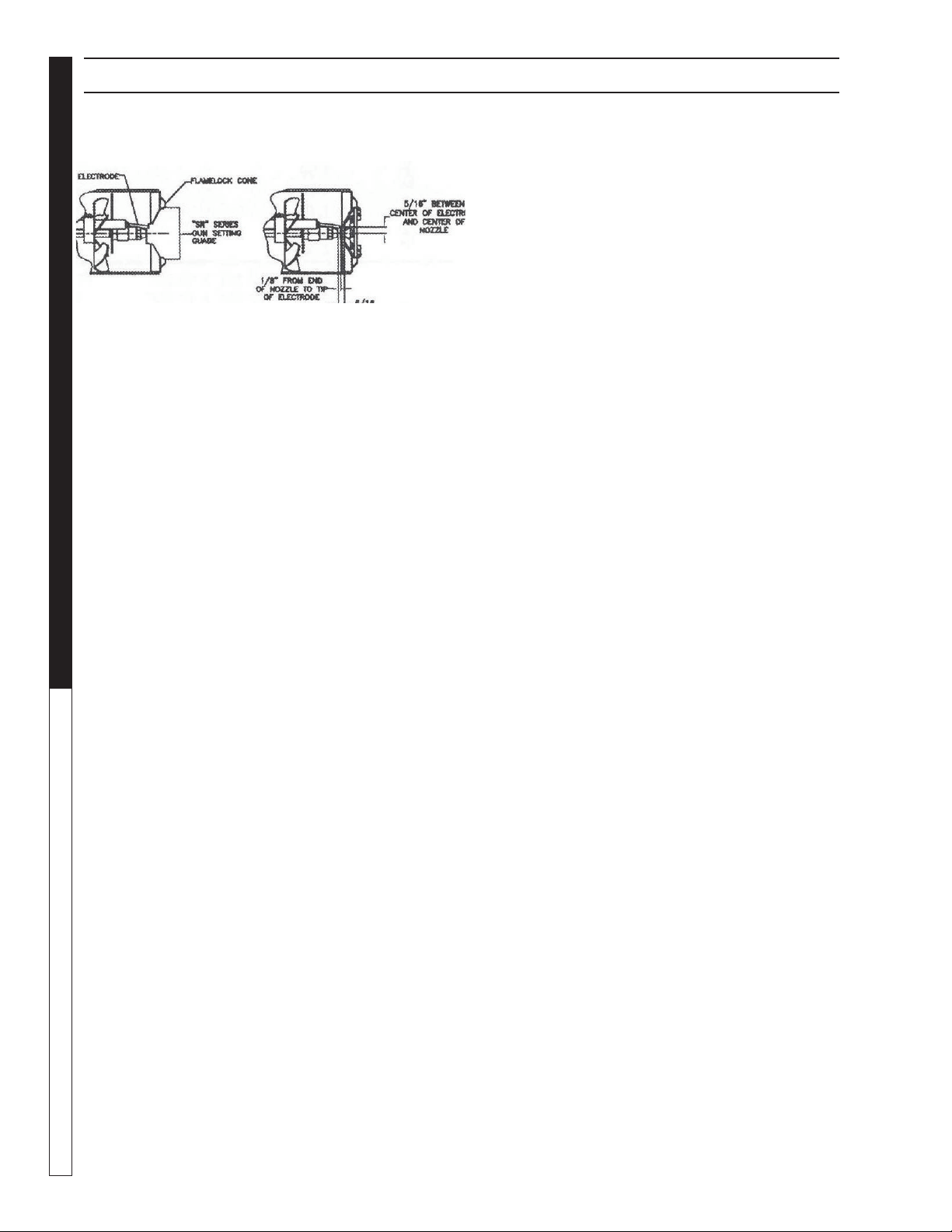
Periodically Check Wiring Connections. If Necessary
To Adjust Electrodes, Use Diagram.
Electrode Setting:

Kärcher TRS-SSG • Operators • 9.801-330.0-H
23
PRESSURE WASHER
OPERATOR’S MAN U AL - Notes

Kärcher TRS-SSG • Operators • 9.801-330.0-K
PRESSURE WASHER Troubleshooting Guide
24
PRESSURE WASHER TROUBLESHOOTING
PROBLEM POSSIBLE CAUSE SOLUTION
LOW
OPERATING
PRESSURE
Faulty pressure gauge Install new gauge.
Insuffi cient water supply Use larger supply hose; clean fi lter at water
inlet.
Old, worn or incorrect spray nozzle Match nozzle number to machine and/or
replace with new nozzle.
Belt slippage Tighten or replace; use correct belt.
Plumbing or hose leak Check plumbing system for leaks.
Retape leaks with tefl on tape.
Faulty or misadjusted unloader valve Adjust unloader for proper pressure.
Install repair kit when needed.
Worn packing in pump Install new packing kit.
Fouled or dirty inlet or discharge
valves in pump
Clean inlet and discharge valves.
Worn inlet or discharge valves Replace with valve kit.
Obstruction in spray nozzle Remove obstruction.
Leaking pressure control valve Rebuild or replace as needed.
Slow engine RPM Set engine speed at proper specifi cations.
Pump sucking air Check water supply and possibility of air
seepage.
Valves sticking Check and clean or replace if necessary.
Unloader valve seat faulty Check and replace if necessary.
BURNER
WILL
NOT LIGHT
Little or no fuel Fill tank with fuel.
Improper fuel or water in fuel Drain fuel tank and fi ll with proper fuel.
Clogged fuel line Clean or replace.
Plugged fuel fi lter Replace as needed.
Misadjusted burner air bands Readjust air bands for clean burn.
Little or no fuel pressure from fuel
pump
Increase fuel pressure to specifi cation and/or
replace fuel pump. Test with pressure gauge.
Faulty burner transformer Test transformer for proper arc
between contacts. Replace as needed.
(continued on next
page)
Disconnected or short in electrical
wiring
All wire contacts should be clean and tight.
No breaks in wire

Kärcher TRS-SSG • Operators • 9.801-330.0-K
25
PRESSURE WASHER Troubleshooting Guide
PRESSURE WASHER TROUBLESHOOTING
PROBLEM POSSIBLE CAUSE SOLUTION
BURNER WILL
NOT LIGHT
(continued from
previous page)
Flex coupling slipping on fuel
pump shaft or burner motor shaft
Replace if needed.
On-Off switch defective Check for electrical current reaching burner assem-
bly with burner switch on.
Heavy sooting on coil and burner
can cause interruption of air fl ow
and shorting of electrodes
Clean as required.
Improper electrode setting Check and reset according to diagram in Operator's
Manual.
Fuel not reaching combustion
chamber
Check fuel pump for proper fl ow.
Check solenoid fl ow switch on machines with spray
gun control, for proper on-off fuel fl ow control.
Clogged burner nozzle Clean as required.
Thermostat faulty or slow engine
speed
Increase engine RPM to increase voltage.
Flow switch malfunction Remove, test for continuity and replace as needed.
Flow solenoid malfunction Replace if needed.
FLUCTUATING
PRESSURE
Valves worn Check and replace if necessary.
Blockage in valve Check and replace if necessary.
Pump sucking air Check water supply and air seepage at joints in suc-
tion line.
Worn piston packing Check and replace if necessary.
Gasoline engine altitude The gasoline engine is preset for opera-
tion at altitudes below 1000 ft above sea level.
If operated at higher altitudes, it may be necessary to
install a high altitude main jet in the carburetor. Contact
your local authorized engine sales and service center
for details.
MACHINE
SMOKES
WHILE
BURNER UNIT
IS RUNNING
OR
UNIT SMOKES
AT COLD-START
ONLY WHEN
BURNER
IS OFF
Improper fuel or water in fuel Drain tank and replace contaminated fuel
Improper air adjustment Readjust air bands on burner assembly
Fuel pressure is low <140 psi for
burner
Adjust fuel pump pressure to specifi cations
Burner nozzle is plugged or dirty Replace nozzle. Check parts breakdown
for nozzle size
Burner nozzle spray pattern is
faulty
Replace nozzle. Check parts breakdown
for nozzle size
Heavy accumulation of soot on
coils and burner assembly
Remove coils and burner assembly,
clean thoroughly Call local dealer
Misaligned electrode setting Realign electrodes to specifi cations
Obstruction in smoke stack Check for insulation blockage or other
foreign objects
Low engine RPM Increase RPM to correct specs. See serial plate
Fuel Pressure is too high for
clean burn (fuel PSI above 140
and below 200) and smokes
when burner is off
Reduce fuel pressure PSI/Increase air band set for
cleaner without max water heat loss

Kärcher TRS-SSG • Operators • 9.801-330.0-K
PRESSURE WASHER Troubleshooting Guide
26
PRESSURE WASHER TROUBLESHOOTING
PROBLEM POSSIBLE CAUSE SOLUTION
LOW
WATER
TEMPERATURE
Improper fuel or water in fuel Replace with clean and proper fuel.
Low fuel pressure Increase fuel pressure.
Weak fuel pump Check fuel pump pressure.
Replace pump if needed.
Fuel fi lter partially clogged Replace as needed.
Soot build-up on coils not allowing
heat transfer
Clean coils.
Improper burner nozzle See specifi cations. (Page 31)
WATER
TEMPERATURE
TOO HOT
Incoming water to
machine warm or hot
Lower incoming water temperature.
Fuel pump pressure too high See specifi cations for proper fuel pressure.
Fuel pump defective Replace fuel pump.
Detergent line sucking air Tighten all clamps. Check detergent lines for
holes.
Defective temperature switch Replace.
Incorrect fuel nozzle size See specifi cations for
proper fuel nozzle. (Page 31)
Insuffi cient water supplied Check water G.P.M. to machine.
Restricted water fl ow Check nozzle for obstruction, proper size.
PUMP
NOISY
Air in suction line Check water supply and connections on suc-
tion line.
Broken or weak inlet or discharge
valve springs
Check and replace if necessary.
Excessive matter in valves Check and clean if necessary.
Worn bearings Check and replace if necessary.
PRESENCE
OF WATER
IN OIL
Oil seal worn Check and replace if necessary.
High humidity in air Check and change oil twice as often.
WATER
DRIPPING
FROM
UNDER PUMP
Piston packing worn Check and replace if necessary.
O-Ring plunger retainer worn Check and replace if necessary.
Cracked piston Check and replace if necessary.
Pump protector Lower water supply pressure. Do not run
with spray gun closed longer than 2 minutes

Kärcher TRS-SSG • Operators • 9.801-330.0-K
27
PRESSURE WASHER Troubleshooting Guide
PRESSURE WASHER TROUBLESHOOTING
PROBLEM POSSIBLE CAUSE SOLUTION
OIL
DRIPPING
Oil seal worn Check and replace if necessary.
EXCESSIVE
VIBRATION
IN DELIVERY
LINE
Irregular functioning of the valves Check and replace if necessary.
DETERGENT
NOT
DRAWING
Air leak Tighten all clamps. Check detergent lines for
holes.
Incorrect nozzle Use chemical nozzle.
Filter screen on detergent suction
hose plugged
Clean or replace.
Dried up detergent plugging me-
tering valve
Disassemble and clean thoroughly.
High viscosity of detergent Dilute detergent to specifi cations.
Hole in detergent line(s) Repair hole.
Low detergent level Add detergent, if needed.
PUMP RUNNING
NORMALLY
BUT PRESSURE
LOW ON
INSTALLATION
Pump sucking air Check water supply and
possibility of air seepage.
Valves sticking Check and clean or replace if necessary.
Nozzle incorrectly sized Check and replace if necessary
(See serial plate for proper size).
Unloader valve seat faulty Check and replace if necessary.
Worn piston packing Check and replace if necessary.
BURNER
MOTOR WILL
NOT RUN
Fuel pump seized Replace fuel pump.
Burner fan loose or misaligned Position correctly, tighten set screw.
Defective control switch Replace switch.
Loose wire Check and replace or tighten wiring.
Defective burner motor Replace motor.
RELIEF VALVE
LEAKS WATER
Relief valve defective Replace or repair

Kärcher TRS-SSG • Operators • 9.801-330.0-K
OPERATOR’S MANUAL
PRESSURE WASHER
28
PRESSURE WASHER PREVENTATIVE MAINTENANCE
OIL CHANGE RECORD
Check pump oil level before fi rst use of your new Power Washer. Change pump oil after fi rst 50 hours and
every 3 months or 500 hours thereafter. Use SAE 10W-40 weight oil, non-detergent.
Date Oil Changed
Month/Day/Year
No. Of Operating Hours
Since Last Oil Change
Brand Name and
Type of Oil (See above)
MAINTENANCE SCHEDULE
Engine Oil
Inspect Daily
Change Every 25 hours
Filter Every 50 hours
Air Cleaner
Inspect Rupture Disk
Clean Every 3 months
Battery Level Check monthly
Engine Fuel Filter 500 hours or 6 months
Spark Plug Maintenance 500 hours or 6 months
Clean Fuel Tank(s) Annually
Replace Fuel Lines Annually
Pump Oil
(Non-detergent
SAE 10W-40)
Inspect Oil level daily
Change After fi rst 50 hours, then every 500 hours or annually
Clean Burner Filter Monthly (More often if fuel quality is poor)
Remove Burner Soot Annually
Burner Adjustment/Cleaning Annually
Replace Burner Nozzle Annually
Descale Coil Annually (More often if required)
Replace High Pressure Nozzle Every 6 months
Replace Quick Connects Annually
Clean Water Screen/Filter Weekly
Replace HP Hose Annually or as needed
Diverter Valve Cable Lube Cable Weekly
Rupture Disk Replace every 2 years
This pressure washer was produced with the best available materials and quality craftsmanship. However,
you as the owner have certain responsibilities for the correct care of the equipment. Attention to regular
preventative maintenance procedures will assist in preserving the performance of your equipment. Contact
your dealer for maintenance. Regular preventative maintenance will add many hours to the life of your
pressure washer. Perform maintenance more often under severe conditions.

Kärcher TRS-SSG • Operators • 9.801-330.0-K
29
PRESSURE WASHER
OPERATOR’S MAN U AL
This trailer was produced with the best available materials and quality craftsmanship. How-
ever, you as the owner, have certain responsibilities for the correct care of the equip-
ment. Attention to regular preventative maintenance procedures will assist in preserving
the performance of your equipment.
MAINTENANCE SCHEDULE
Tire Air Pressure
Infl ate to proper pressure indicated on sidewall Every Trip
Wheel Lugs, Bolts, Nuts
ans Wheel Mount
Tighten to proper torque specifi cations Every 3000 mi or 3 mos.*
Wheel
Check for damage and or out-of-round Every 6000 mi or 6 mos.
Coupler Ball
Check for suffi cient lube.
Check lock mechanism.
Check for unusual wear.
Every trip
Safety Chains at Hitch Ball
Check for abrasion, distortion
and general integrity of links.
Every trip
Coupler
Check for proper fastening & hitch pin
in position and secure.
Every trip
Brakes
Check for proper adjustment & operation Every trip
Breakaway Switch
Test switch operation and connections Every trip
Breakaway Battery
Pull switch pin, check charge indicator light Every trip
Load Distribution
Check load distribution & security Every trip
Welds
Check all weld beads for cracks or separations Every 6000 mi. or 6 mos.
Electrical: Lights & Signals
Check to make sure all are
working properly. Replace burned out bulbs.
Every trip
* Check lug nuts for tightness before initial trip, at 10 miles, 25 miles and 50 miles. Recheck at least every 3 months or 3000 miles
Axles, Hubs and Brakes
Maintenance for axles, hubs and brakes is extremely important for protecting the longevity
of your trailer. It is extremely important for your personal safety and the protection of oth-
ers.
Please, never shortcut axle, hub and brake service and maintenance.
TRAILER PREVENTATIVE MAINTENANCE

www.karchercommercial.com
Form # 9.801-330.0 • Printed in U.S.A. or Mexico
Rate your product and tell us your opinion.
Évaluer votre produit et dites-nous votre opinion.
www.kaercher.com/welcome
www.kaercher.com/dealersearch
Alfred Kärcher SE & Co. KG
Alfred-Kärcher-Str. 28-40
71364 Winnenden (Germany)
Tel.: +49 7195 14-0
Fax: +49 7195 14-2212
DANKE!
THANK YOU!
MERCI!
GRACIAS!
!
Registrieren Sie Ihr Produkt und protieren Sie von vielen Vorteilen.
Register your product and benet from many advantages.
Enregistrez votre produit et bénécier de nombreux avantages.
Registre su producto y aproveche de muchas ventajas.
Bewerten Sie Ihr Produkt und sagen Sie uns ihre Meinung.
Reseñe su producto y díganos su opini
ó
n