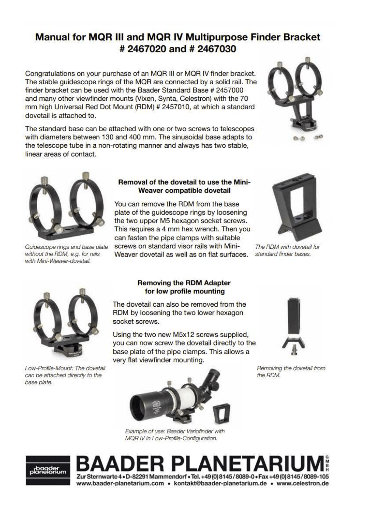
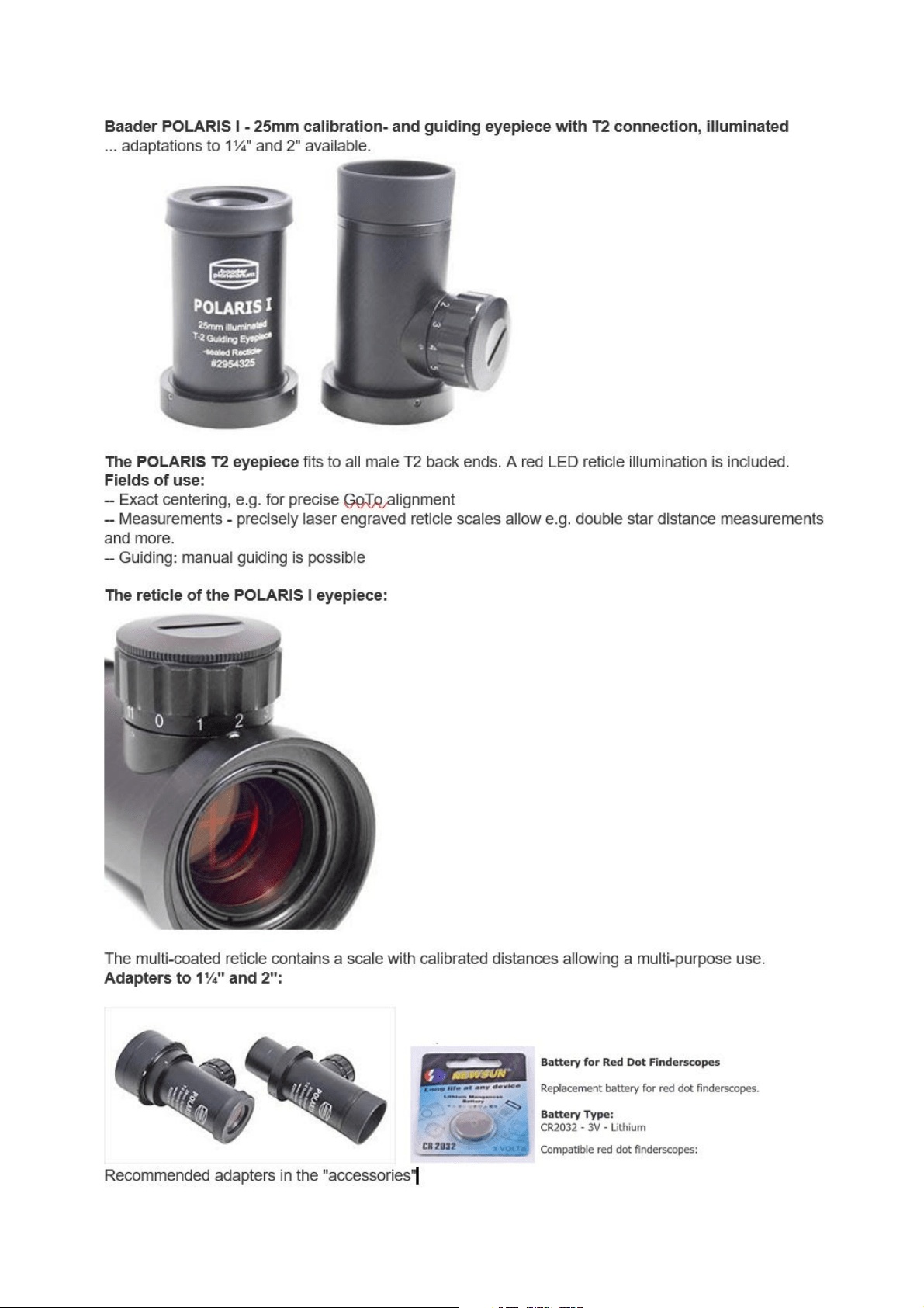
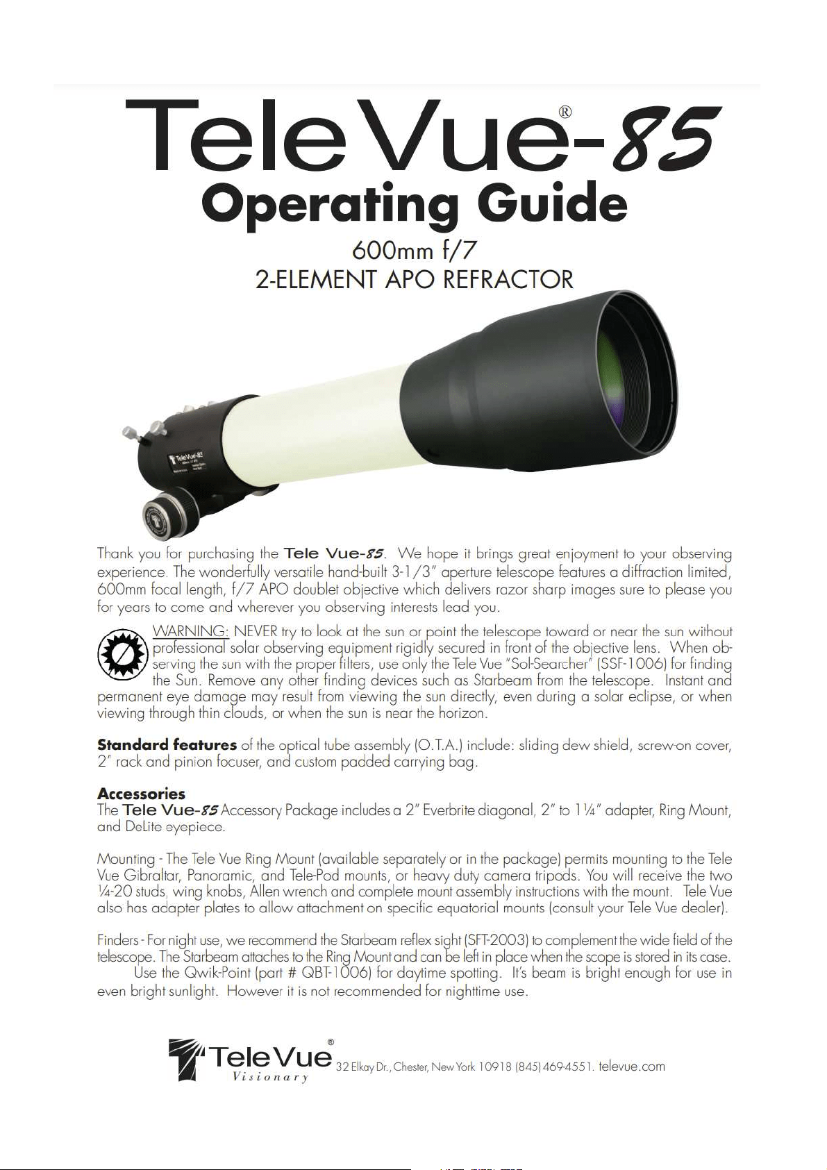
1
The Hermes Traveller is the first ever universal single-tube
telescope for viewing, planetary & deep space object astro-
photography… all in one… portable… and only possible with
Rotarion.
by AstronSCIENTIFIC SL
1.1. Introduction:
1.1. The Hermes Traveller, characteristics & highlights:
• First ever single tube telescope for eyepiece viewing and astro-photography for both imaging
techniques: a) moon & planets and b) deep space objects (DSO) such as galaxies, nebulae, etc..
• The telescope is recommended for intermediate, advanced, and expert amateurs or professionals
in astro-photography.
• State of the art, best quality parts and components supplied from best industry brands.
• Light weight, portable single tube telescope supplied with a military grade quality transport case.
• Hardware quick and easy setup, estimated time under 2 minutes:
o Red color aluminum handle for easy telescope lift, carry and assembly, from the transport
case to your mount & tripod and back.
o Steel counter-weight in dove-tail bar for easy telescope balancing.
o Fully integrated astronomy telescope components ready for use.
▪ Telescope tube, motorized focuser, Rotarion wheel, Rotarion CAM Kit parts and
Rotarion AutoFocus, optics and astro-photography cameras integrated, including
a DSO camera off-axis guide system.
▪ No need to assemble or un-assemble the Hermes Telescope when changing
telescope viewing or astro-photography application.
• Astronomy applications and setups by Rotarion wheel Ports #:
o Port 1: Viewing
o Port 2: Deep Sky Objects (DSO) astro-imaging.
o Port 3: Not available in this telescope.
o Port 4: Moon and Planets astro-imaging.
The HERMES TRAVELLER
2
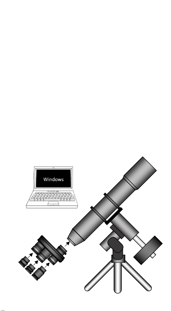
1.2. Extra equipment you will need to operate the Hermes Traveller:
• Equatorial Goto Mount: Celestron Mount Advanced VX AVX type or with higher payload capacity.
• PC or Laptop computer with Windows 10.
• Imaging capture software and post-processing software (in the web there are free software apps).
• Reliable Power source or Power tank 12 Volt.
• Foldable table, chair, red flashlight, warm clothes…
1.3. In the box:
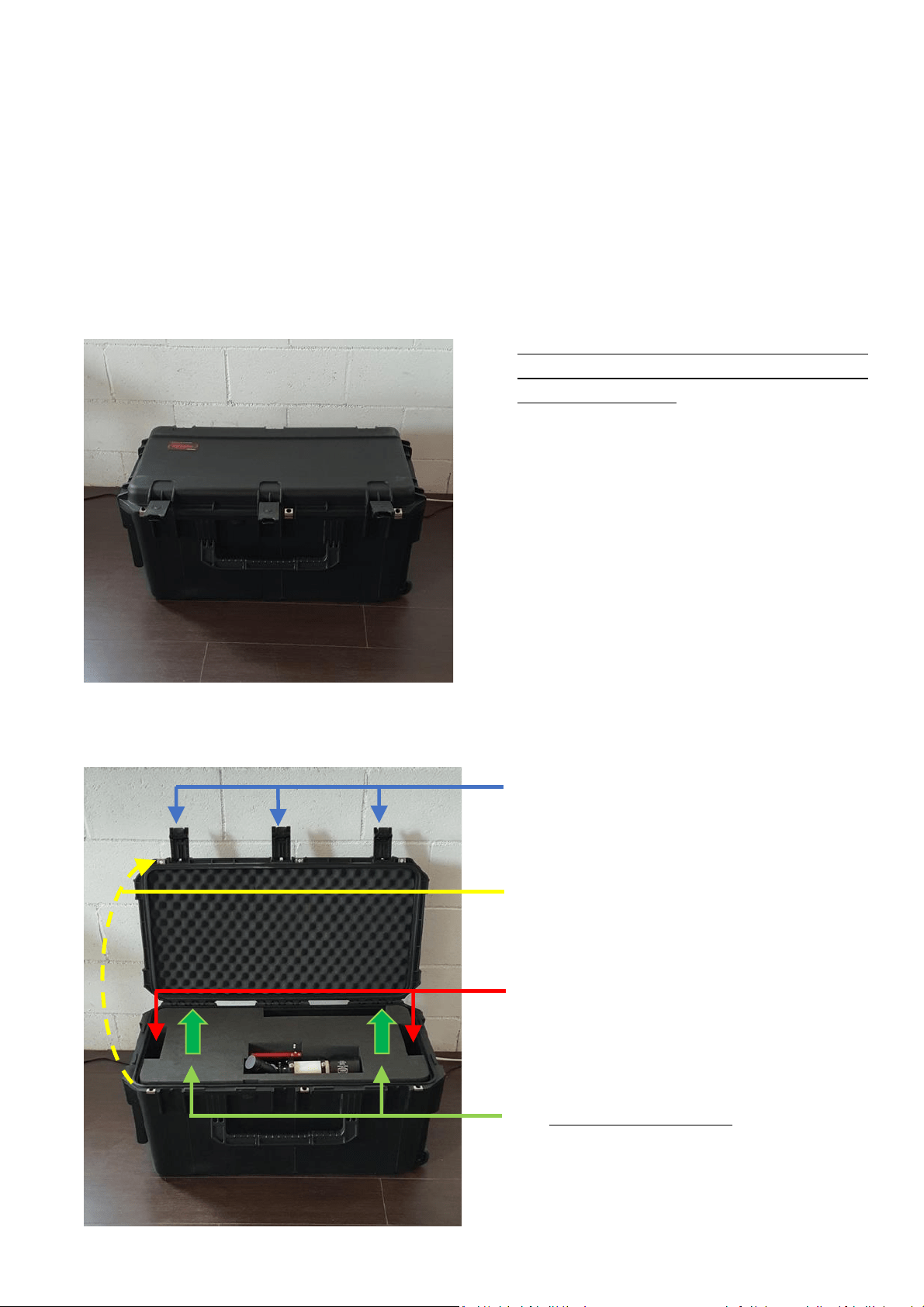
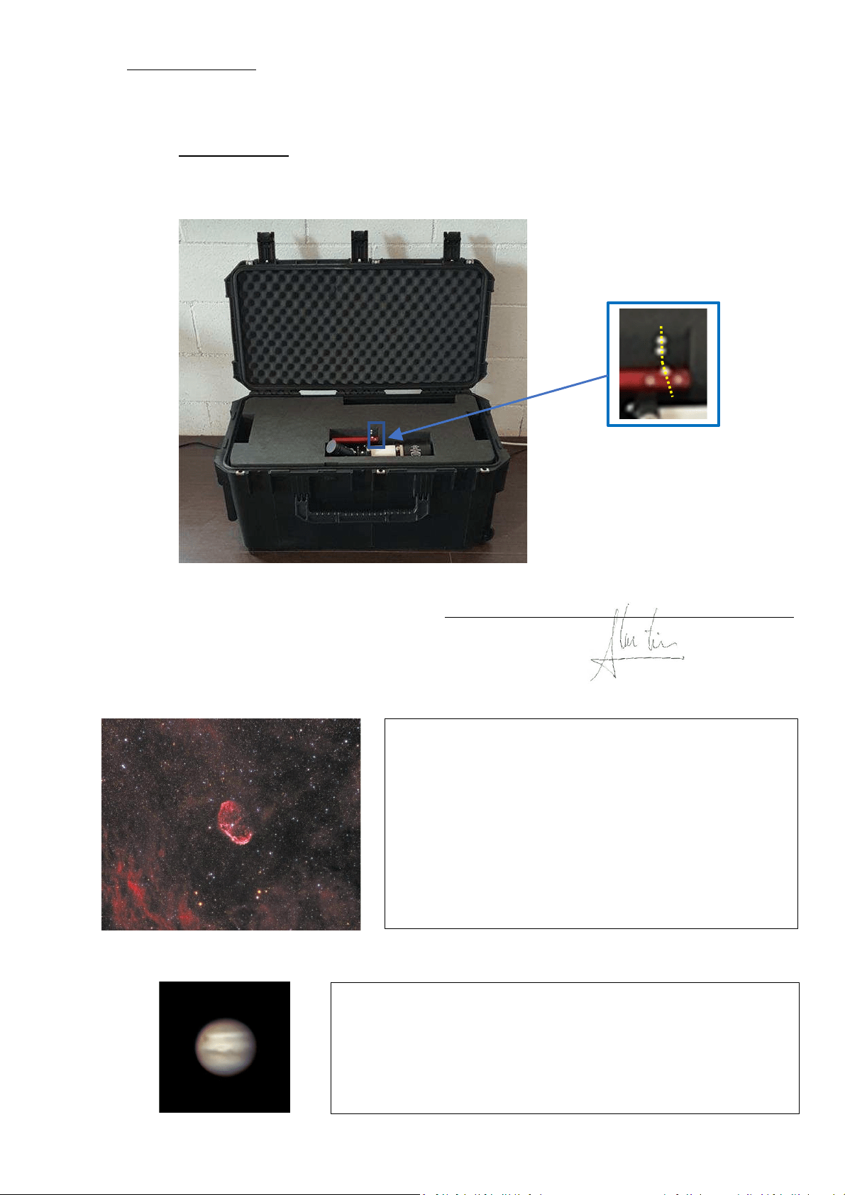
3.1. Hermes Traveller transport case.
Watertight military suitcase with custom foam
and with integrated telescopic handle (trolley)
and 2 pulling wheels. Rotational molded case
for extreme strength of military certificates
(MIL-STD-810F). Powder-coated black
stainless-steel latches and extremely strong
hinges. Ergonomic handles. Dust and water-
tight (MIL-C-4150J, IP67) with automatic
compression valve (MIL-STD-648C), resistant
to UV rays, solvents, corrosion and fungi (MIL-
STD-810F). MATERIAL: Roto-molded poly-
ethylene (LLDPE). RESISTANCE: High. COLOR
Black. LATCHES Black painted steel butterfly
latches - padlock ring. STACKABLE: yes.
3.2. Opening the transport case.
A) Release and open the black 3 hinges,
B) Open the case.
C) Grab with both hands the upper foam.
D) CAREFULLY lift vertically the upper foam.
3
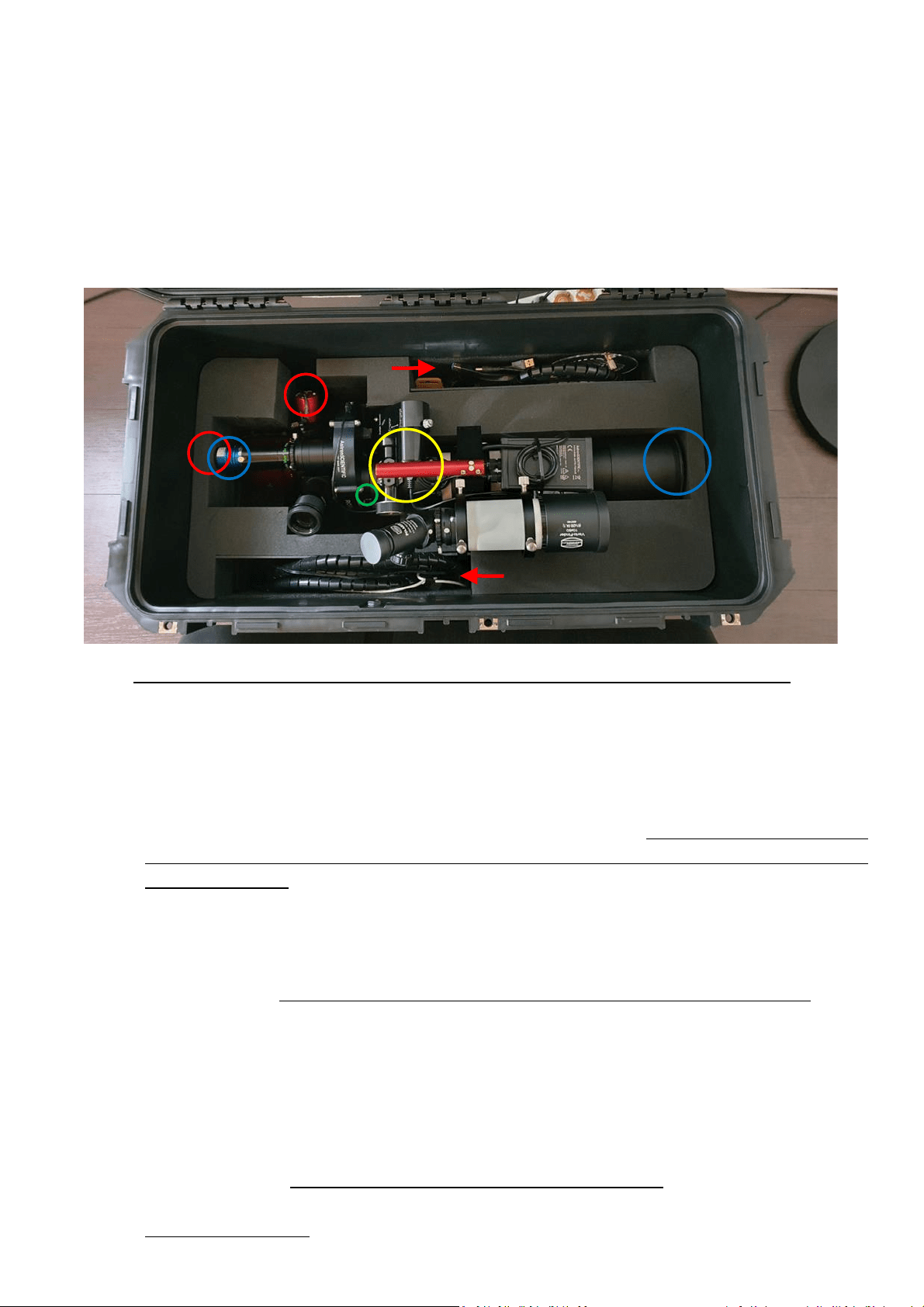
3.3. Inside the Hermes Traveller’s transport case.
• The Hermes Traveller telescope:
• 2 pairs of pre-packed wire-hoses for easy connection to pc/laptop and to power supply.
o Rotarion wheel power and remote control.
o Rotarion AutoFocus and motor focuser power and remote control.
• 1 Bahtinov transparent mask, for extra fine manual infinite focusing for DSO imaging.
• 1 Instruction Manual printed folder.
- Observe how the Hermes Traveller telescope is placed inside the foam -
3.4. The telescope fits tight in the water-cut foam.
A) Right side blue circle: observed the telescope is closed with the black metal safety cap on; the
safety cap presses the black foam wall.
B) Left side blue circle: The planetary QHY blue color camera is placed all the way inside the TeleVue
x5 PowerMate (release the seen screw and thight it again) so the camera does NOT touch the
left side foam wall.
3.5. All telescope integrated wiring is connected and ready for use, EXCEPT:
A) Red color circles: NO wires are connected to any camera nor the filter wheel (not seen); that is
to prevent power and USB connectors to be broken under transport stress.
B) Red color arrows: Two long wire black hoses (to be connected later to a pc or laptop computer
and to power supply) are safely placed among other items.
3.6. How to remove the Hermes Traveller from the case:
A) Yellow color circle: Grab with 1 hand ONLY (recommended left hand) on the red color aluminum
Handle.
B) Carefully lift vertically the Hermes Traveller using ONLY the red color aluminum Handle.
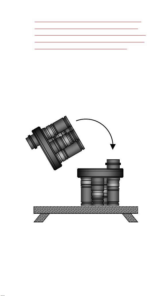
4
C) Place the telescope dove- tail bar on your tripod mount, tighten all screws in your mount (See in
your tripod mount the Instructions Manual).
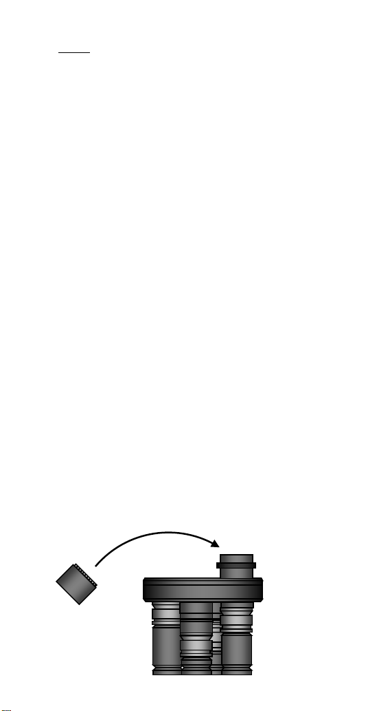
D) Remove telescope front-end metal cap, connect cameras and filter wheel wires (power and USB),
connect 1 dot) black wire hose to Rotarion, and 2 dots) black wire hose to cameras; both wire
hoses ends connect to pc or laptop and to power supply.
E) Proceed with telescope balancing routine (see in YouTube videos of how to balance a telescope).
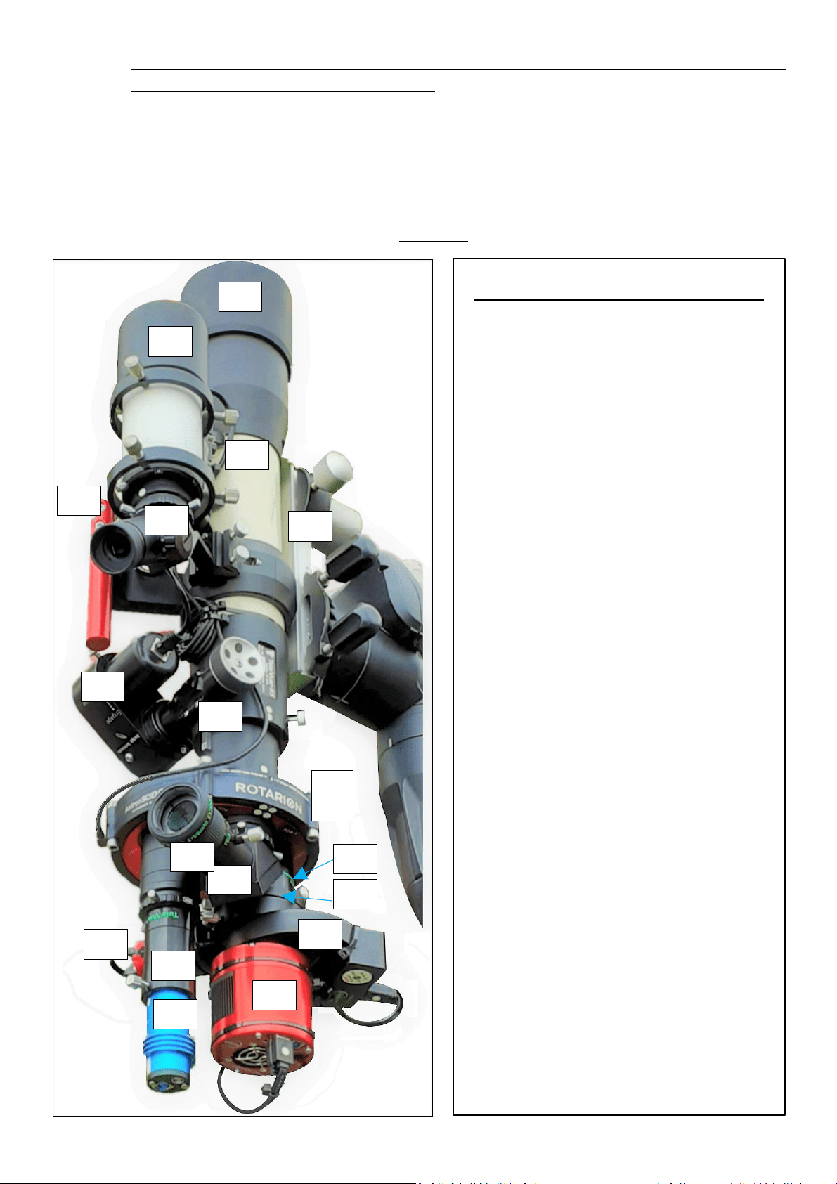
1.4. Operating the Hermes Traveller (see ANEX: Manufacturer’s Instruction Manuals Index)
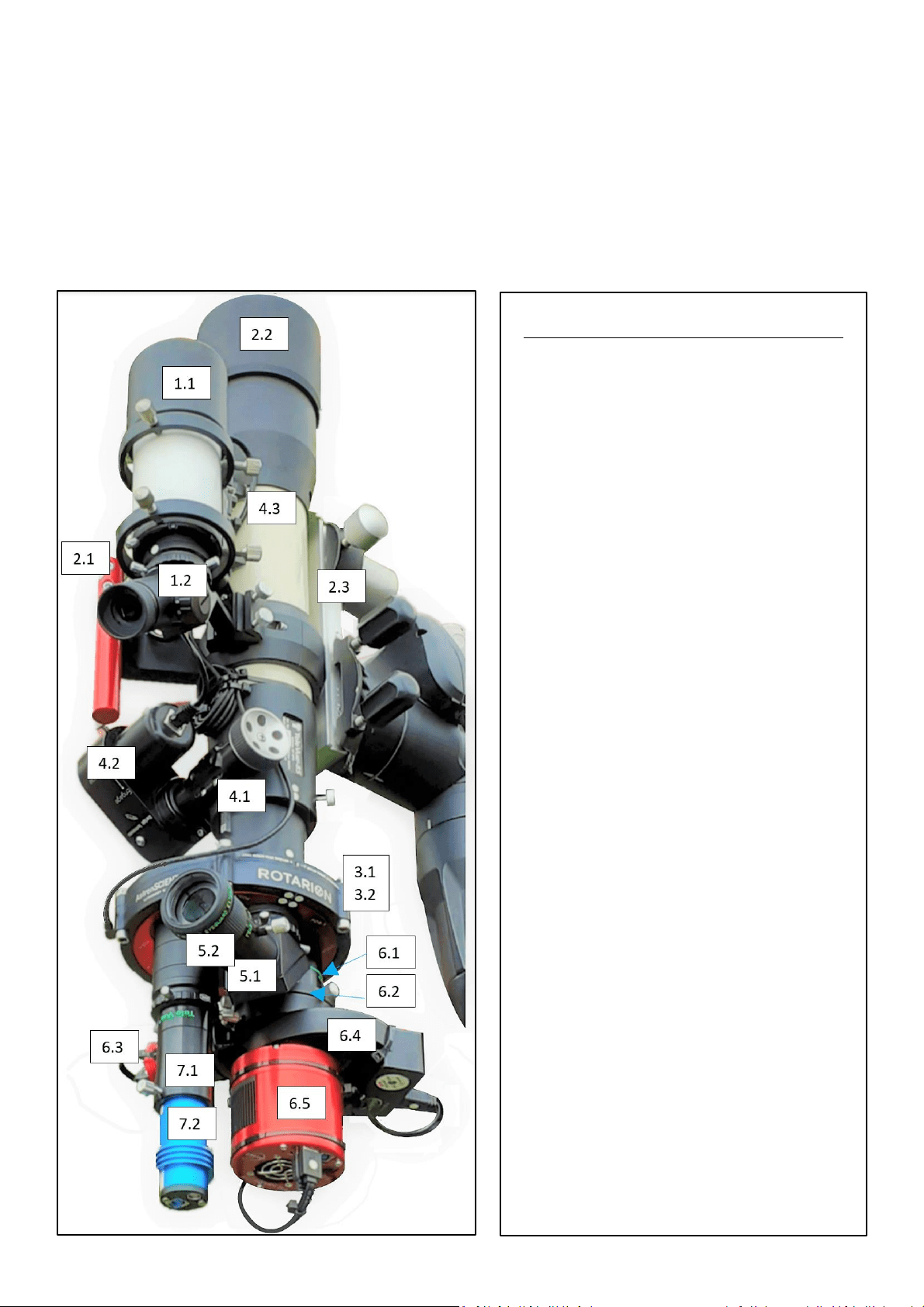
- INDEX FOR MANUFACTURER’S MANUALS -
1. Spotter/Finder:
1.1. Baader
1.2. Baader Cross-hair finder eyepiece.
2. Telescope tube:
2.1. Hermes Traveller Handle-bar.
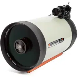
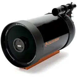
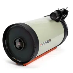
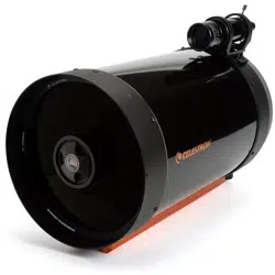
2.2. TeleVue Inc TV-85.
2.3. Dovetail-bar and steel counter-
weight.
3. Rotarion remote wheel:
3.1. Rotarion & Rotarion Remote
Control software.
3.2. Rotarion CAM Kit & Rotarion
Remote Control PRO software.
4. Focusing:
4.1. TeleVue TV-85 focuser
4.2. StarLight motor focuser.
4.3. Rotarion Autofocus (only wires
seen in this image).
4.4. Bahtinov Mask (inside the case).
5. Port # 1: Viewing:
5.1. TeleVue Diagonal
5.2. TeleVue 40mm Plössl eyepiece +
TeleVue EyeGuard Extender.
6. Port # 2: Deep Space Object astro-
photography:
6.1. TeleVue TV-85 Reducer &
Flattener optic Custom for
Rotarion.
6.2. M48 TS quick release adapter +
ZWO off-axis guide.
6.3. ZWO guide camera.
6.4. ZWO filter wheel + Baader RGBL+H
Alpha filters (inside ZWO filter
wheel).
6.5. ZWO Monochrome cooled
camera.
7. Port # 4: Planetary astro-photography:
7.1. TeleVue PowerMate x5 optic.
7.2. QHY color camera.
1.1
1.2
2.2
2.1
2.3
3.1
3.2
4.1
4.2
4.3
5.1
5.2
6.1
6.2
6.3
6.4
6.5
7.1
7.2
5
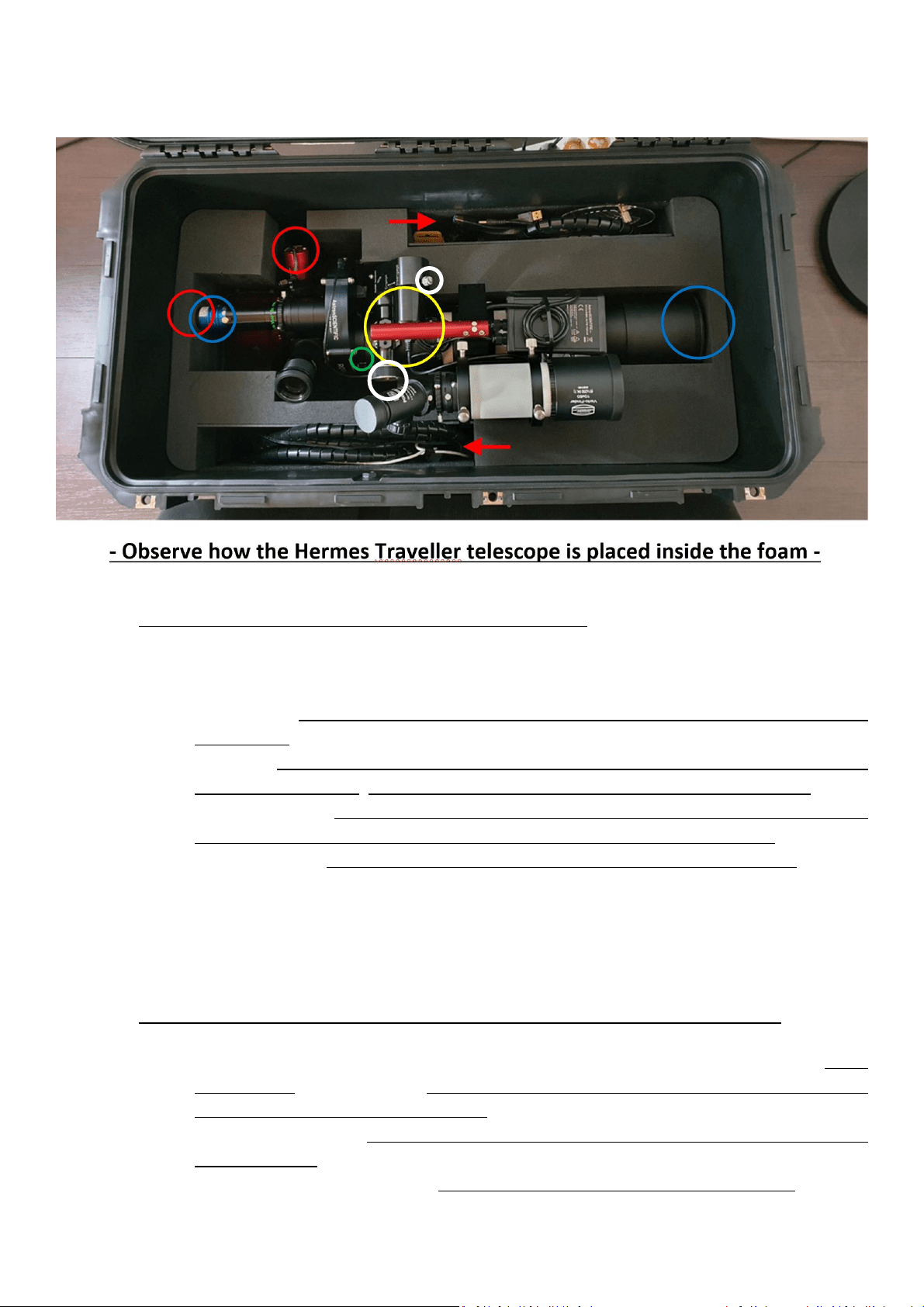
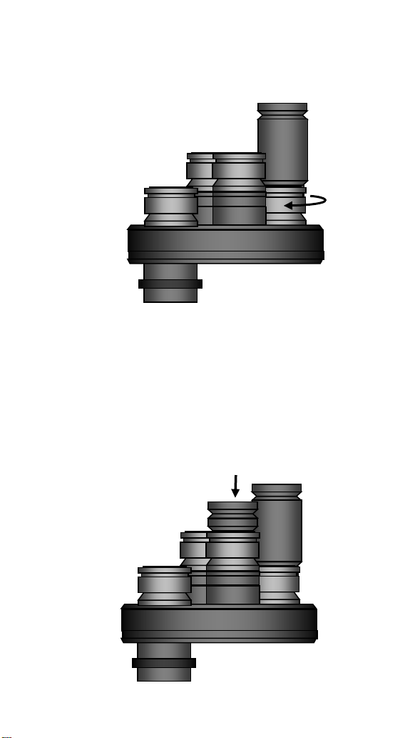
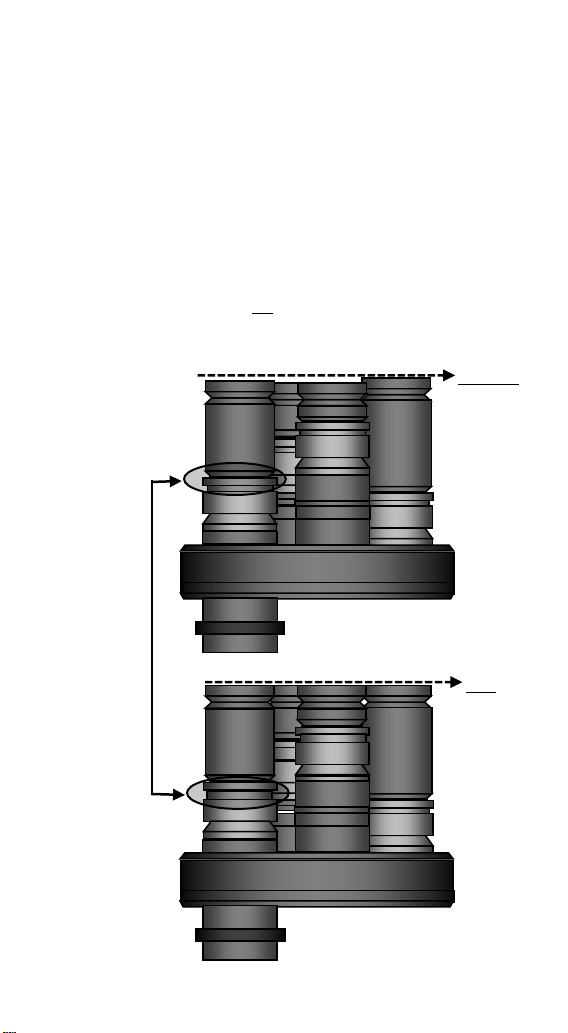
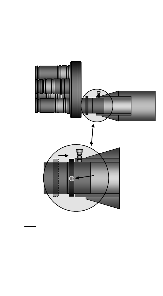
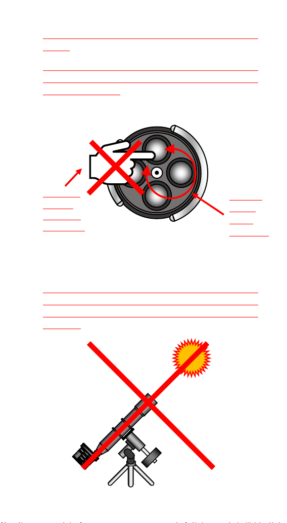
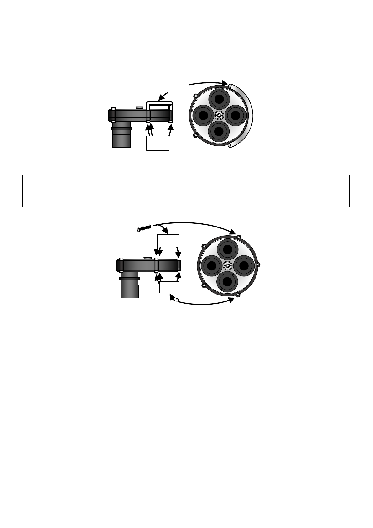
1.5. How to place the Hermes Traveller in the case for safe transport & storage:
A) BEFORE removing the telescope from your mount & tripod.
a. Close the telescope front-end black metal safety cap.
b. Green color circle: carefully unlock the 2 barrel hand-screws found in the telescope
focuser, then rotate until aligned the fluorescent dots found in the telescope focuser and
the Rotarion wheel; lock again the 2 screws found in the telescope focuser.
c. Make sure Port # 1 TWO fluorescent dots in red Rotarion carrousel are aligned on Rotarion
TWO fluorescent dots. This will ensure the correct fit of the telescope in the foam.
d. White color circles: unlock screw in motor focuser first, second using focuser wheel move
the focuser to maximum inward position; finally lock screw in motor focuser.
e. Red color circles: Disconnect wires connected to any camera or the filter wheel.
f. Red color arrows: Disconnect 2 black color wire hoses with connectors, power and USB;
place both back wires hoses in the case.
g. Carefully grab and hold the Hermes Traveller red aluminum handle and remove the
telescope from your mount & tripod.
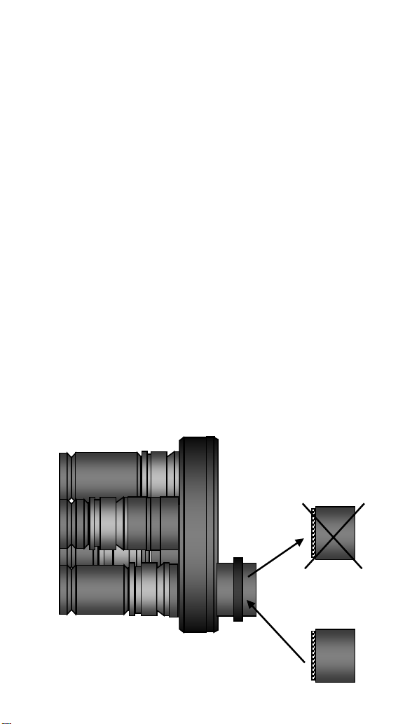
B) AFTER removing the telescope from your mount & tripod, placing theinside the foam
a. Right side blue color circle: Holding the telescope by the red aluminum handle-bar, lower
it CAREFULLY inside the foam, making sure the front-end of the telescope tube is leaning
until touching the foam wall as shown.
b. Red Color circles: with previously disconnected all power and USB connectors of cameras
and filter wheel (not seen), so they connectors won’t break because they touched the
foam walls around the cameras, PRESS downward the telescope inside the foam using the
handle ONLY.
6
C) CLOSING the Case:
a. See image on 3.2 Opening the transport case.
b. Sept sequence C), B) and A).
i. Note on step C): the fluorescent 2 dots on the black upper foam plus the 2 dots on Hermes
Traveller’s red handle must be aligned to properly place the foam before B) lowering the
case’s lid C) and closing the 3 black hinges.
ii.
iii.
1.6. Quality Control and final Field Tests: Hermes Traveller Serial Number #001.
A) Quality Control: Feb 17,2021, signed by inventor Alv. Martinez ______________
B) Field Test Port # 2: DSO image:
C) Filed Test Port # 4: Planetary image:
The Crescent Nebula NGC6888, Constellation Swan.
5000 light years away, discovered by William Hersell 1792.
Good Seeing conditions.
Hermes Traveller: OTA TV85 - ZWO ASI1600MMC PRO -
Filters R, G, B, H Alpha. Baader.
10 subs of Halpha 300" BIN 1 - 10 subs of each R,G,B filters of
120s BIN 2.
Captured SGPro / Processed AstroPixelProcessor, Pixinsight,
and Photoshop.
By Carlos Uriarte - October 2020 – The Pyrenees – Spain.
Jupiter.
588 Million Km away. Poor Seeing conditions.
Hermes Traveller: OTA TV85 – TeleVue PowerMate x5 QHY Color.
40,000 Frames – Selected best 20%.
Captured FireCapture / Processed AutoStakker, Astra and Photoshop.
By Josep Soldevilla - October 2020 – Barcelona – Spain.
7
ANEX
Hermes Traveller #0001,
Manufacturer’s Integrated Components Instruction Manuals Index.
- INDEX FOR MANUFACTURER’S MANUALS -
1. Spotter/Finder:
1.1. Baader
1.2. Baader Cross-hair finder eyepiece.
2. Telescope tube:
2.1. Hermes Traveller Handle-bar.
2.2. TeleVue Inc TV-85.
2.3. Dovetail-bar and steel counter-
weight.
3. Rotarion remote wheel:
3.1. Rotarion & Rotarion Remote
Control software.
3.2. Rotarion CAM Kit & Rotarion
Remote Control PRO software.
4. Focusing:
4.1. TeleVue TV-85 focuser
4.2. StarLight motor focuser.
4.3. Rotarion Autofocus (only wires
seen in this image).
4.4. Bahtinov Mask (inside the case).
5. Port # 1: Viewing:
5.1. TeleVue Diagonal
5.2. TeleVue 40mm Plössl eyepiece +
TeleVue EyeGuard Extender.
6. Port # 2: Deep Space Object astro-
photography:
6.1. TeleVue TV-85 Reducer &
Flattener optic Custom for
Rotarion
6.2. M48 TS quick release adapter +
ZWO off-axis guide.
6.3. ZWO guide camera.
6.4. ZWO filter wheel + Baader RGBL+H
Alpha filters (inside ZWO filter
wheel).
6.5. ZWO Monochrome cooled
camera.
7. Port # 4: Planetary astro-photography:
7.1. TeleVue PowerMate x5 optic.
7.2. QHY color camera.
8
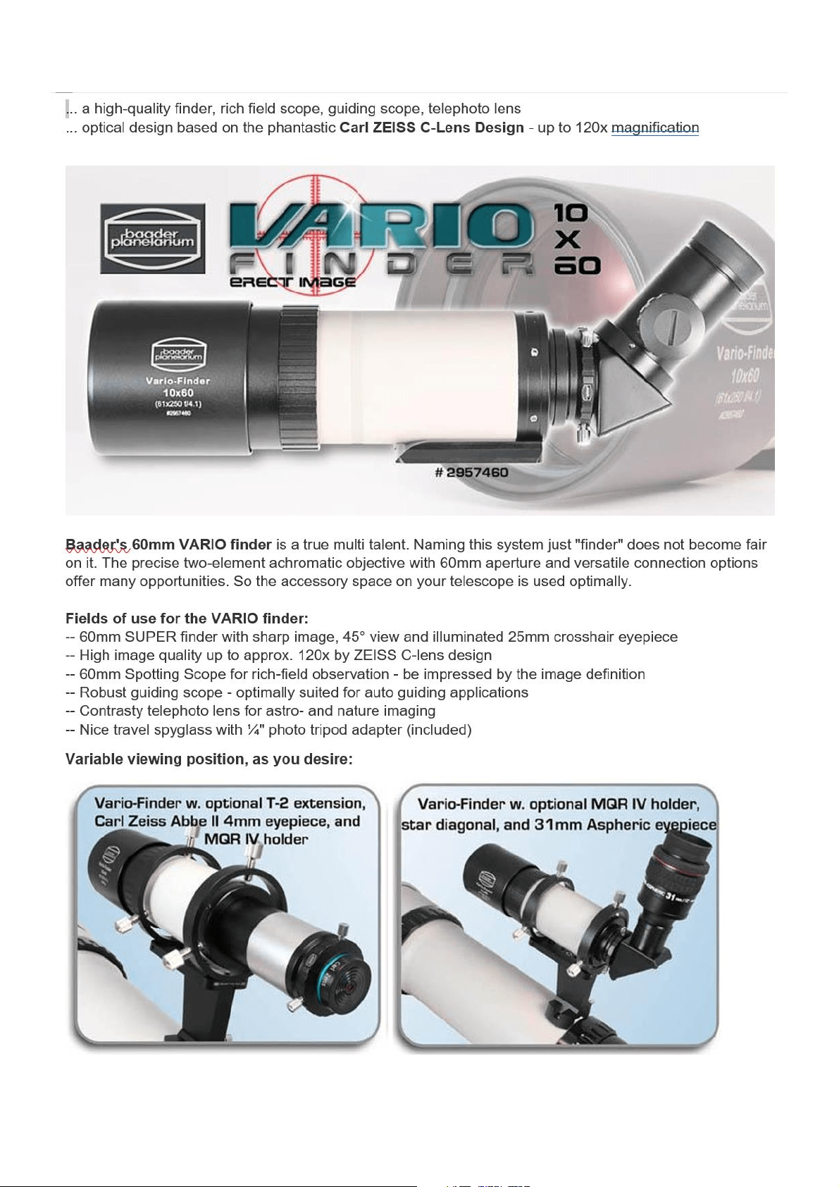
1.1. Baader 60mm VARIO Finder - with 60/250mm ASTRO objective
The Baader VARIO Finder offers useful T2 connection and 1.25" also. Beneath cameras, you can connect
1.25" accessories like diagnoals, Amici prisms etc. Within a minute, this system can be altered from a straight
telescope to a comfortable 90° right angle finder.
9
10
11
1.2. Baader 60mm VARIO Finder - with 60/250mm ASTRO objective
12
2.1. TeleVue Inc TV-85
13
14
15
16

17
3.1. Rotarion & Rotarion
Remote Control software.
18

19
Congratulations on your purchase of ROTARION!
ROTARION is designed and manufactured to be used
for daytime terrestrial observation and for nighttime
astronomical observation.
ROTARION is a unique device, patented in the
European Union and the United States, to be used
with any telescope with a 2" focuser and four of your
favorite 1.25" eyepieces.
For the first time ever, you can change the power or
magnification of your telescope with just a simple
click, connecting your ROTARION remotely to a
Windows computer with the ROTARION REMOTE
CONTROL software included in this box.
ROTARION makes the eyepiece change easy.
Automatic, quick, and precise without touching the
telescope therefore avoiding disturbances in the
positioning or misalignment of the optical axis
between eyepieces. No more searching in the dark
for your next eyepiece!
The automatic eyepiece change allows you to adjust
the correct magnification on your telescope by
increasing or decreasing the focal length of the
eyepiece used, the "zoom effect".
Re-locate lost objects out of the field of view due to
improper alignment or poor tracking of the
telescope. Quick change to your largest eyepiece in
mm number to maximize visual field and re-locate.
All with a simple Click!
And with the Rotarion automatic eyepiece change
you can use higher power eyepieces than you ever
had before. Now you can discover the joy of bigger
and better views with higher magnification!

20
ROTARION is a device of the highest quality,
designed and manufactured in BARCELONA with
state-of-the-art techniques and the best materials
and components from the US, Japan, and Germany.
First, read this Instruction Manual and follow the
assembly instructions step-by-step. If you follow the
assembly instructions correctly, even if the assembly
is initially laborious, the use of ROTARION is very
simple and easy.
All this to offer you many hours of enjoyment
observation, and satisfaction with your telescope.
Maximum quality, universal, versatile, and easy to
use, ROTARION continues our corporate mission:
AstronSCIENTIFIC
Astronomy Made Easy

21
In the box
• ROTARION, The EyepieceWheel.
• ROTARION REMOTE CONTROL software for PC or
Windows computer (USB Stick / Pen-Drive).
• USB cable for Windows computer control.
• Serial cable for Windows computer control.
• AC Power Adapter 110-240 Volt / DC 12 Volt with
international AC adapters.
• 12 Volt wire with car-plug adapter.
• 4 units, Baader Click-Lock 1,25" eyepiece-adapter.
• 3 units, rings "Extenders" M42 - 5mm focal length to
adjust eyepiece heights.
• 3 units, rings "Extenders" M42 - 10mm focal length to
adjust eyepiece heights.
• 3 units, rings "Extenders" M42 - 20mm focal length to
adjust eyepiece heights.
• 2 units, 2” barrel 30mm length for 2” focuser, with
filter thread.
• 1 unit, 2” retainer ring to adjust position in your 2"
focuser.
• User's manual.
• Telescope, eyepieces, optics and other ROTARION
products or accessories not included.
22
System Requirements
To operate ROTARION EyepieceWheel and ROTARION
REMOTE CONTROL software you need the following
equipment:
Not included in the box:
• A telescope with a 2 "focuser (A).
• A mount and telescope tripod or column that
supports the weight of the telescope, the weight of
your 4 eyepieces to be used and 2Kg extra (B).
• 4 eyepieces of 1.25" with maximum outer diameter
50mm (C).
• Computer or Windows PC (D).
Included in the box:
• ROTARION EyepieceWheel (E).
• ROTARION REMOTE CONTROL Software.
(A)
(B)
(C)
(D)
(E)

23
Index
A-ROTARION The EyepieceWheel
1. Introduction
2. Selecting your eyepieces for ROTARION
3. Mounting your eyepieces in the ROTARION
4. Mounting the ROTARION on your telescope
B-ROTARION REMOTE CONTROL Software
1. Installing the Software
2. Connecting the ROTARION
3. Status LED
4. Start of ROTARION
5. ROTARION REMOTE CONTROL screen
6. Setup screen
7. ROTARION REMOTE CONTROL ports
8. Warning Messages
C-Using the ROTARION and ROTARION
REMOTE CONTROL Software
1.
CAUTION! MOVING PARTS!
2. Observing position
3. Observing objects with the ROTARION
4. The "Zoom Effect"
5. The "Finder Effect"
D-Additional Product Information
1. Product Compliance Information
2. Service, Maintenance, Cleaning, Disposal, Serial
Number, and Dealer
E-Warranty
1. Warranty Period
2. Warranty Coverage
3. Warranty Nullity

24
A-ROTARION
The EyepieceWheel
1. Introduction
Change the power-magnification of your telescope with a
simple Click.
The AstronSCIENTIFIC’s ROTARION EyepieceWheel is a
universal and automatic eyepiece exchanger. You can
automatically quick-change eyepieces and any other
optics. The eyepiece change is easy, fast, and accurate,
without touching the telescope, and therefore avoiding
disturbances or deviations in the positioning of the optical
axis of the telescope.
2. Selecting your eyepieces for the
ROTARION
Choose 4 of your favorite eyepieces based on a scaling
provided by the mm indicated in each eyepiece. From a
large field of view eyepiece, with the lowest magnification
and greatest number in mm, to the eyepiece with smaller
number in mm, smaller field of view and greater
magnification. It is important that the intermediate scaling
between the mm of each eyepiece is as proportional as
possible.
Example:
As you observe in the data sheet on the following page,
you have 6 available 1.25" eyepieces with different
magnifications (mm) and you select 4 eyepieces so that the
scaling of the magnification between them is as
proportional as possible.
25
When selecting a proportional scaling, you ensure that
when you order the ROTARION to change an eyepiece, the
next eyepiece will always show you the object you are
observing.
CAUTION: ROTARION is designed to accept 1.25”
eyepieces with a maximum 50mm outer/external
diameter. Depending on combinations with other smaller
outside diameter eyepieces, you may exceed the
maximum outside diameter of 50mm at your discretion
and your responsibility.
3. Mounting your eyepieces in the
ROTARION
Remove the ROTARION from the box and observe the 4
ports:
• Port [PORT-1], 12 hours of a traditional clock (A).
• Port [PORT-2], 3 hours of a traditional clock (B).
• Port [PORT-3], 6 hours of a traditional clock (C).
• Port [PORT-4], 9 hours of a traditional clock (D).
Eyepiece mm Eyepiece mm
TeleVue 40 TeleVue 40
TeleVue 35
Meade 28 Meade 28
Baader 17 Baader 17
Celestron 10
Celestron 8 Celestron 8
Available
Selected
(A)
(C)
(B)
(D)
(A)
(D)
(C)
(B)
26
Once the 2 eyepieces with the greatest and the smallest
number of mm and the 2 intermediate have been selected
according to their best proportional scaling, you will align
them from lower magnification (largest mm) to higher
magnification (smallest mm) to verify their differences in
height between them.
The difference in heights between the eyepieces should be
compensated by combining the 5mm, 10mm, and 20mm
M42v0,75 Extenders supplied in the ROTARION threaded
to 3 of the 4 supplied Baader Click-Locks.
You select the largest height eyepiece (in this case the
17mm) corresponding to position number 3 in the series of
4 eyepieces on this page, we will place it in port [PORT-3]
of the ROTARION, corresponding to the Hour 6 of a
traditional clock, unscrewing first the "Extenders"
mounted under the Baader Click-Lock.
1. Unscrew Extenders from 5mm, 10mm and 20mm of
the Baader Click-Lock.
Extenders:
5mm
10mm
20mm
Baader
Click-Lock
1,25”
28mm
17mm
m
8mm
40mm
m
27
2. Thread the Baader Click-Lock back on the ROTARION.
3. Mount the highest height eyepiece (in this example
17mm) in the Baader Click-Lock.
17mm
28mm
17mm
8mm
40mm
1. Remove!
2.
28
4. Once inserted in the Baader Click-Lock, rotate the
center cylinder of the Click-Lock Baader (4) clockwise
to hold the eyepiece in the Click-Lock eye-cup.
5. You will proceed inserting the following eyepieces of
lowest height, matching the height of the eyepiece
with the necessary "Extenders". Following the
example, you proceed to mount the eyepiece of
lowest height, in this case, the eyepiece of 8mm,
which corresponds to the position 4 of the series of
eyepieces drawn at the beginning of this Section 3, in
the port [PORT-4] of your ROTARION .
17mm
8mm
40mm
17mm
(4)
29
6. Note in the drawing of the previous point 5, that the
eyepiece of 8mm mounted in the Baader Click-Lock is
not equal in height to the 17mm eyepiece. Using a
combination of 5mm, 10mm and 20mm available
Extenders, you threaded them into the Click-Lock
Baader of the 8mm eyepiece to match the height of
the 17mm eyepiece. In this case you only need to use
the 20mm Extender, not using the 5mm Extender and
the 10mm Extender. Once the eyepiece has been
installed in its Baader Click-Lock, you proceed to hold
the eyepiece by turning the central part of the Click-
Lock in the clockwise direction, as in the previous
drawing in step number 5.
7. You continue to mount the remaining eyepieces. In
this example, you mount the 28mm eyepiece to the
[PORT-2] port of the ROTARION, corresponding to the
Hour 3 position of a traditional clock, using the extra
"Extenders" to equal the heights of the already
17mm
8mm
30
mounted eyepieces. In this case, you only use the
"Extender" of 5mm.
8. Finally, on the following page, you assemble the
remaining eyepiece. In this example, the eyepiece of
least power and greatest number of mm and greatest
field of view, the 40mm eyepiece in port [PORT-1] of
the ROTARION, corresponding to Hour 12 of a
traditional watch. If necessary, you will use the spare
Extenders. In this example, you thread the "10mm
28mm
40mm
28mm
17mm
8mm
31
Extender2 in the Baader Click-Lock to match the
height to the rest of the eyepieces.
9. Once all eyepieces have been assembled by
combining the Baader Click-Locks and the 9
"Extenders" included in the ROTARION, it is possible
that you must perform a "fine-tuning" of all final
heights to accurately match the height of the 4
eyepieces mounted on the ROTARION. To do this, you
will use the helical adjustment of the Baader Click-
Lock that has an additional travel of 6-7mm by turning
the top ring (10).
40mm
28mm
17mm
8mm
40mm
(10)
32
10. You perform the heights adjustments using the top
helical rings of the Baader Click-Locks according to the
previous step 9. In this example, you adjust the height
of the 40mm, 28mm and 8mm eyepieces to equal the
height of the 17mm eyepiece. Note the small
difference in height of the 40mm eyepiece Baader
Click-Lock, before and after the fine adjustment,
indicated by an arrow (10). The result, indicated in the
second figure of this page, are the heights alignment
of the 4 eyepieces mounted in the ROTARION,
indicated with an OK.
(10)
28mm
17mm
8mm
40mm
No Ok.
Ok.
17mm
28mm
8mm
40mm
33
11.
CAUTION! Once all the heights have been adjusted
by means of the helical adjustment of the Baader
Click-Locks, ensure that the eyepieces are secured to
the Baader Click-Lock by turning the central cylinder
according to the drawing in previous step 4.
12. For the final verification of height adjustment of your
eyepieces, an easy method is to place the ROTARION
and its eyepieces face down on a flat surface, for
example a table, ensuring that the eyepieces are
firmly attached to the Baader Click-Locks as indicated
on previous point 4, to avoid any eyepiece fall.
13. If the ROTARION placed face down on the table is not
stable, you must adjust again the heights between
eyepieces using the helical top ring of the Click-Lock
Baader, as indicated in previous step 10.
17
28
8
40
34
NOTE: Currently there are more than 500 models of
eyepieces in the international market and although the
ROTARION has been verified with many models of 1.25”
eyepieces, it is normal to have some unused Extenders
(Spacers). But it is also possible, although unlikely, that in
a particular case, the differences in height between your
eyepieces are very large and you will need some additional
"Extenders” (or Spacers), in addition to the 9 "Extenders”
(or Spacers) included in the ROTARION’s box. In which
case, in your usual astronomy store, you should be able to
purchase additional "Extenders" (or Spacers) M42x0,75 of
different heights, since it is a standard component.
4. Mounting the ROTARION on your
telescope.
If you have not mounted your four 1,25” eyepieces in the
ROTARION you must follow the previous instructions of
this manual, Chapter A, Sections 2, and 3 which explains
the selection of eyepieces and the assembly of eyepieces
in ROTARION.
After completing the method of selection and assembly of
the eyepieces in the ROTARION, according to Sections 1, 2
and 3, you proceed to mount your ROTARION in your
telescope.
1. Remove the additional 2” barrel from the box and
thread it to the 2" barrel with retaining ring already
mounted on the ROTARION.
35
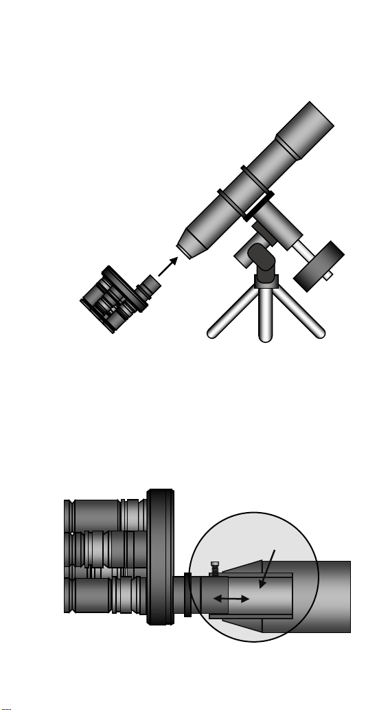
2. Insert the ROTARION into the 2 "focuser female draw-
tube of your telescope and hold the ROTARION to
your telescope by firmly tightening the 2" focuser
screws of your telescope.
3. If you do not find the correct focus point with your
telescope, unscrew the fastening screws of your
focuser (A) and move the ROTARION position on the
2" female draw tube of the focuser (B), sliding it in or
out with care (C). Once the correct focus point is
reached, retighten the retaining screws of your
focuser (A) firmly.
(B)
(C)
(A)
36
4. Once you have reached the optimum position of the
ROTARION on the 2 "female of your telescope's focus,
use the 2" movable retaining ring (A) in the lower
drawing, unscrewing and re-screwing the micro
screws (B) to “memorize” the correct position of the
ROTARION in your telescope’s focuser.
NOTE: After adjusting the position of the ROTARION within
the 2” female draw-tube of your focuser, your telescope
must allow the focus of the 4 eyepieces by the exclusive
use of the wheel or motor of your focuser. Due to the large
number of types and models of 2" telescopes and focusers
on the market, it is possible that you may not reach focus
with all eyepieces. It can happen with some Newton type
reflecting telescopes or also in some refractor models. In
A.
A.
B.
37
your usual astronomy store you can find Barlow lenses and
optical path corrector lenses, either "Focal Point
Extenders" or "Path Correctors" for telescopes and
focusers with little focal travel range, or with back-focus
limitations. In the specific case of Newton-type telescopes,
there are several manufacturers of "Coma" corrective
lenses that further extend the focal length of the telescope
by solving the "back-focus" limitations.
Optics such as "Barlows", "Focal Point Extenders" and
"Path Correctors" with focal length extension should be
installed by replacing the (A) 2” barrel in the ROTARION.
AstronSCIENTIFIC cannot recommend specific optics (B) to
increase focal travel due to the enormous number of
eyepiece combinations, its later leveling through the
“Extenders” in the ROTARION and the specific back focus
needs of each telescope. At your usual specialized store,
they can recommend the optics that suits your specific
needs of your telescope.
To reach focus in refractors and Newtonians a 2-inch
Barlow (B) x2, x3 x4 or a combination of them works fine.
(A)
(B)
38
The use wedges or diagonal prisms or Amici (A) prisms
shortens or reduces the focusing length/range of the
telescope, but this does not mean any difficulty in focusing
with the most common and popular reflector telescopes
such as Schmitt-Cassegrain, Ritchey-Chretien, Maksutov or
similar (B) of great focal travel/range.
For refractors we recommend the Te le Vue 2” Everbrite
Diagonal for Rotarion.
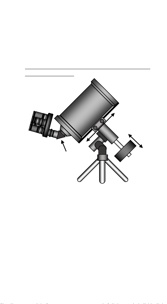
5. Finally, with the ROTARION mounted on your
telescope, you must balance the telescope. There are
many videos on YouTube where you can learn how to
balance a telescope. In the upper drawing, the 2 basic
actions of telescope balancing adjustment are shown:
1-adjustment of the counterweight (C) and 2-
adjustment of the optical tube assembly (D).
With the ROTARION and eyepieces mounted on your
telescope and having balanced your telescope, you
continue to Chapter B-ROTARION REMOTE CONTROL
software.
(A)
(B)
(D)
(C)

39
B-ROTARION REMOTE
CONTROL Software
1. Software Installation
To install the software ROTARION REMOTE CONTROL you
need a computer or PC with Windows and a USB
connector.
Load the Pen-Drive / USB-Stick included. On the Pen-Drive
/ USB-Stick you will find the installation file of the
ROTARION EyepieceWheel program called "Setup". Run
that file and follow the instructions to install the program.
The program will be located in the Windows Start menu
under Programs> ROTARION> ROTARION REMOTE
CONTROL.
No need to install drivers for the ROTARION. The USB port
is an HID device that Windows recognizes automatically
and the serial port input does not use a special driver.
Once the installation is completed, the next time you
connect the ROTARION to your computer, it will remember
that this device has already been installed once and will
recognize it automatically.
40
2. Connecting the ROTARION
The ROTARION EyepieceWheel has 3 options for interface
control. Two options with the ROTARION REMOTE
CONTROL software through a USB port, or via a Serial port
or a third option without a Windows PC computer with
hand controller accessory named ROTARION HAND
CONTROL.
USB connection: A USB port can be used to control the
ROTARION The Eyepiece Wheel. Then the only required
connection is a USB cable included in the box between the
USB port of the ROTARION EyepieceWheel (3) and a USB
port of the computer or Windows PC.
If the USB port does not have sufficient power, or if you are
using the ROTARION PHOTO accessory, it is necessary to
(1) Power input
(2) Serial Port
(3) USB Port
(4) Status Led
(5) Focuser Port
ROTARION EyepieceWheel connectors
5
4
3
2
1

41
connect the 12-volt power supply to the power input (1).
Serial Port Connection: Can also be controlled via a
serial port. It requires a special RJ12 cable labeled "R-
S", included in the box, connected between the serial
port of the ROTARION (2) and a serial port on the
Windows computer or PC.
This interface is mandatory if you are going to use the
ROTARION AUTOFOCUS accessory.
Serial port control does not require any special drivers.
Only determine the correct COM port in the [SETUP] panel
drop-down list (Chapter 4, item 10).
For this interface, it is necessary to connect the 12-volt
power supply to the input (1).
Connection ROTATION HAND CONTROL: It can also
be controlled via a handset via the serial connection
(2).
ROTARION HAND CONTROL is available from
AstronSCIENTIFIC distributors. The kit includes a
ROTARION HAND CONTROL with Bluetooth, the
ROTARION AUTOFOCUS software pre-installed (without
the ROTARION AUTOFOCUS hardware) and an RJ12 cable
to connect it to the serial port of the ROTARION
EyepieceWheel (2).
The 12-volt power supply must be connected to the input
(1).
42
3. Status LED
Normally the LED of the ROTARION (4) is green, changing
to red color when the ROTARION carousel/wheel rotates.
The following table describes all possible cases.
Color
Blink
ROTARION EyepieceWheel STATUS
Green
No
Stopped. Ready to be activated.
Green
Yes
Initial Warning
Red
No
ROTARION Turning
Red
Yes
[ERROR]
4. ROTARION activation
Start the ROTARION REMOTE CONTROL program. This will
display the eyepiece wheel control screen for the first
time.
Press the [SETUP] button (7) to open / close the Setup
panel,
Select the port you are using, USB port or COM port from
the drop-down menu (10).
6 7 8 9 10 11 12 13
1
16
17 18 19
ROTARION REMOTE CONTROL screen. [SETUP] open.
43
Press the [QUERY] key (13) to manually connect to the
ROTARION. The next time you start the program, you will
automatically connect to it.
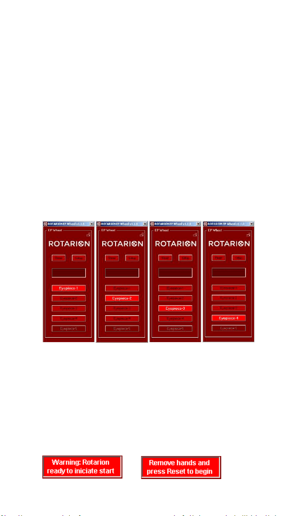
The display shows the initial Warning message, indicating
that the ROTARION is ready to start and
REMOVE THE
HANDS AND OBJECTS BEFORE PUSHING THE [RESET]
BUTTON.
READ CHAPTER C SECTION 1, CAUTION! MOVING PARTS!
BEFORE PROCEEDING.
Press the [RESET] button (6) and the ROTARION
EyepieceWheel carousel does full rotation movements in
one direction and the opposite direction during which it
performs a calibration and determines the number of
available ports. When the process is finished, it stops at the
[PORT-1] port. It is ready for use.
5. ROTARION REMOTE
CONTROL screen
The main screen of the ROTARION REMOTE CONTROL
program, with the [SETUP] screen closed, looks like this:
6 7 8
14
16
ROTARION REMOTE CONTROL screen. [SETUP] closed.
44
[Setup]
Pressing the [SETUP] button (7) opens or closes the set-up
panel, leaving the ROTARION REMOTE CONTROL basic
screen.
[Reset]
For safety reasons, the ROTARION does not start the
turning of the carousel or wheel (A) automatically;
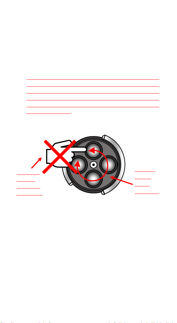
Indicates that it is ready to start the turn and for you to
remove hands, cables and objects (B) that may interfere
with the turning of the ROTARION carousel before pressing
the [RESET] Button.
By pressing the [RESET] button (6), the ROTARION does full
rotations in one direction and the opposite direction
during which it performs a calibration and determines the
number of available ports. When the process is finished, it
stops at the [PORT-1] port. It is ready for use.
[Display]
In this display (14) information messages appear during
ROTARION operation. In case of an error or important
MOVING
PARTS!
Wheel
turning (A)
CAUTION!
Remove
hands and
objects! (B)

45
WARNING, the message with the background illuminated
in Red color appears. For complete information, see the
next point 8, WARNING MESSAGES in this chapter.
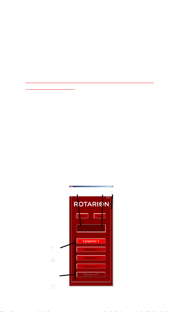
[Port Buttons]
Using the [PORT-1] buttons to [PORT-4] (16), you indicate
to the ROTARION REMOTE CONTROL which eyepiece you
will choose. When you press one of them the ROTARION
will rotate to select it. The button lights up when it has
reached the port. The labels of these buttons can be
changed on panel (17) by pressing [SETUP] to access that
screen.
[Panel Orientation]
By pressing the Horizontal / Vertical orientation icon (8),
the ROTARION REMOTE CONTROL screen changes from
portrait to landscape mode and vice versa. You can move
it around the screen by dragging it with the mouse. The
program memorizes the relative positions of each
orientation.
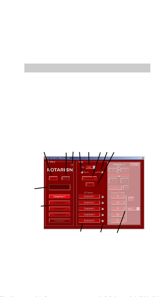
6. Setup screen
Select the [SETUP] button (7) to open the ROTARION
REMOTE CONTROL setup panel.
ROTARION REMOTE CONTROL screen, Horizontal orientation
46
[Port Selection]
Select the port you are using, USB port or
COM port from the drop-down menu (10).
You can then press the [QUERY] key (13) to manually
connect to the ROTARION; The next time you start the
program ROTARION REMOTE CONTROL will automatically
connect to it.
[Revers]
With box (9) de-activated, the ROTARION EyepieceWheel
rotates in counter clock wise direction only. Activating this
box, the rotation movement is bidirectional, but it limits
the rotating movement to port [PORT-4]; once it reaches
that port the ROTARION can only return to previous ports
in a revers motion. [Led ON]. Activate this if you are
6 7 8 9 10 11 12 13
14
16
17 18 19
ROTARION REMOTE CONTROL Display. Open setup

47
using heating bands with wires mounted around your
optics or cameras to prevent wires entanglements.
[LED on]
With the box lit (12), the status LED of the EyepieceWheel
(5) remains lit. Normally the LED is green, changing to red
when the Wheel turns. With the box off (12) you turn off
the LED so that it does not disturb during night
observations.
[Close Setup]
Close the ROTARION REMOTE CONTROL configuration
panel (11).
[Query]
When you press [QUERY] (13), the connection to the
ROTARION is started manually. Normally it is not necessary
to press it since when the program is started it is
connected automatically. But if you change the
communication port, the connection is stopped, and it will
necessary to start the connection manually, or to exit and
restart the program.
[Eyepiece Name Panel]
In this panel (17) you can give the name of the eyepiece
that you place in each port. These names will appear on
the home screen. Example: [PORT-1] = 1-TeleVue 40;
[PORT-2] = 2-Meade 28; etc. By means of the boxes (18) it
is possible to cancel a port by unchecking the box. Useful if
you do not mount an eyepiece.
[Focuser Panel]
In this panel (19) you can adjust everything related to the
ROTARION AUTOFOCUS accessory, which is explained in
48
detail in its own User Manual.
If you have the ROTARION AUTOFOCUS accessory, in the
[FOCUSER CONFIG] Panel you can activate the checkbox
indicated on the previous page [MINI CONTROL], so that
the AUTOFOCUS Control appears at the bottom of the
main screen of the ROTARION REMOTE CONTROL
program.
Please refer to the ROTARION AUTOFOCUS Instruction
Manual.
49
7. Rotarion Remote Control
Ports
You must have installed
[PORT-1] to [PORT-4]
eyepieces ordered from
lowest to highest power
according to Chapter A point
2.
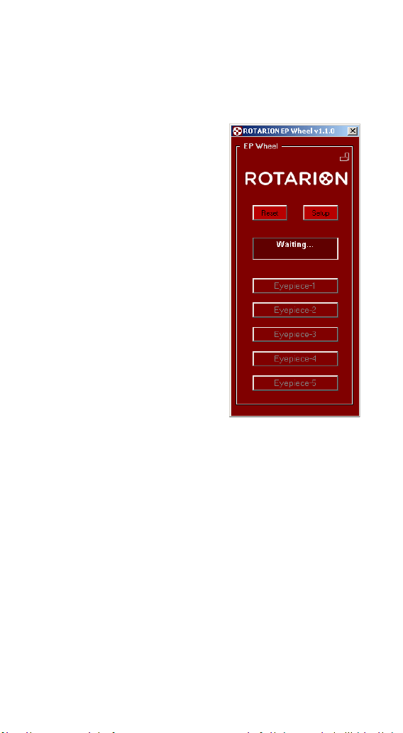
GOTO n
When you press the [PORT-1]
button to [PORT-4] the
ROTARION EyepieceWheel
begins to turn until it locates
that port.
During the time its turning,
the display shows WAITING ...
and the keys are locked. Once
the port is reached, the keys
are unlocked and the selected
port lights up.
[PORT-1]
It is the initial port of the ROTARION once the [RESET] has
been made. In it you must have installed the eyepiece with
least power or magnification and largest field of view. This
will make it easier to find the celestial object for
observation.
[PORT-2]
In this port, you have selected an eyepiece with a higher
power than the previous [PORT-1]. The visual field is
smaller, but if you have focused the object in [PORT-1], it
is easy to re-focus because the object is in the visual field
of view.
GOTO in progress
50
[PORT-3]
In this port, you have selected an eyepiece with a higher
power than the previous [PORT-2]. The visual field is even
smaller, but you have the object in the visual field of view.
You can focus on it again.
[PORT-4]
In this port, you have selected an eyepiece with a higher
power than the previous [PORT-2]. The objects appear
larger and the visual field is smaller, but you have the
object in the field of view. You can focus on it again.
[PORT-5]
This port is not available in this version of the ROTARION
EyepieceWheel.
8. Warning Messages
The display (14) shows warning messages during
ROTARION operation. In case of an error or important
WARNING, the message with the background illuminated
in Red appears.
[PORT-2]
[PORT-1]
[PORT-3]
[PORT-4]
51
Initial Warning
Each time you connect the ROTARION REMOTE CONTROL
it is necessary to make a [RESET] (6) to find the port [PORT-
1].
For safety reasons, the ROTARION does not start the
rotation of the carousel (A) automatically; Indicates that it
is ready to start the turn and that you remove hands,
cables, and objects (B) that may interfere with the rotation
of the ROTARION carousel before pressing the [Reset]
button. The LED (4) flashes green.
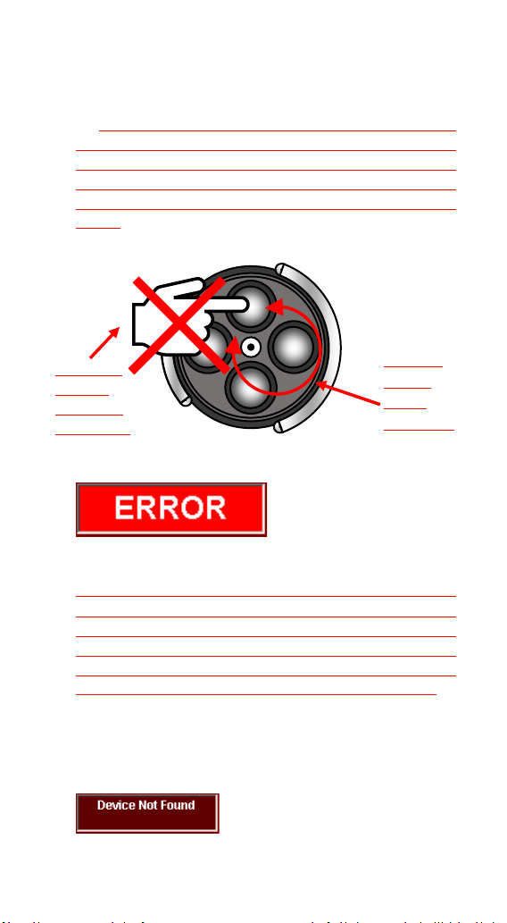
Port Error
For safety reasons, when the ROTARION does not find the
next selected port, it interrupts the rotation movement, it
partially inverts the rotation movement to release any
entrapment of objects and indicates ERROR. Check that
there is no wire or object interfering with the turning of
the ROTARION carousel/wheel. The LED (4) flashes red.
After verifying that no object is interfering with the turning
of the ROTARION, you can press the [RESET] button (6) on
the ROTARION REMOTE CONTROL to restart the device.
MOVING
PARTS!
Wheel
turning (A)
CAUTION!
Remove
hands and
objects! (B)

52
Device Not Found
It cannot find ROTARION through the USB connection.
Verify that you are properly connected and powered.
Port COM Error (computer com port)
It cannot find ROTARION through the serial connection.
Verify that you are properly connected and powered.
Verify that you have selected a correct [COM] port.
Starting Rotarion
The ROTARION is turning for a [RESET]. The LED (4) lights
red.
Waiting...
The ROTARION is turning during the selection of an
eyepiece. The LED (4) lights red.

53
C-Using the ROTARION
and ROTARION REMOTE
CONTROL Software.
1. CAUTION! MOVING PARTS!
ROTARION EyepieceWheel, ROTARION REMOTE CONTROL
software and its accessories are not toys, they are optical
instruments with mechanisms only to be used by adults.
The carousel (A) of the ROTARION EyepieceWheel
performs revolving-type turning movements until reaching
the port requested in the ROTARION REMOTE CONTROL
software.
Remove hands, cables, and other nearby objects (B) that
may interfere with the movement of the ROTARION
EyepieceWheel carouse,l before you order a turn or an
eyepiece or lens change in the ROTARION REMOTE
CONTROL software.
If any object interferes with the rotating movement of the
ROTARION EyepieceWheel carousel by generating an
entrapment and preventing reaching the port indicated in
the ROTARION REMOTE CONTROL, the safety system
automatically activates after 3 seconds, interrupting the
requested turning movement and performing a partial
reverse rotation to release the trap, indicating an [ERROR]
54
message on the ROTARION REMOTE CONTROL software
screen.
Follow the instructions in this manual and the main
message window of the ROTARION REMOTE CONTROL
software at all times.
WARNING!
Do not point your ROTARION and telescope to the sun!
Viewing the sun through a telescope without proper solar
filters will cause severe and permanent eye damage or
blindness!
MOVING
PARTS!
Wheel
turning (A)
CAUTION!
Remove
hands and
objects! (B)
55
2. Observing position
For the visual use of the ROTARION EyepieceWheel you
must place it as indicated in the drawing below.
The user who uses the left eye (A) to visualize must place
the ROTARION to his left. The user who uses the right eye
to visualize must position the ROTARION EyepieceWheel
to his right (B).
In both cases, the ROTARION is positioned in your
telescope to use the lower eyepiece (C) as shown in the
drawing on this page.
A.
B.
C.
56
3. Viewing objects with ROTARION
To locate objects, it more convenient to use your eyepiece
with a greater number of mm or less magnification. The
less magnified eyepieces have the largest field of view and
therefore it is easier to locate objects with your telescope
than with an eyepiece of greater magnification and less
visual field.
If you have followed these instructions correctly, your
lower power or magnification eyepiece should be placed in
the port [PORT-1] of your ROTARION with a larger number
in mm and greater field of view.
Once the observing object is found, you should focus with
the telescope and center the object (A) on the eyepiece
before changing to the next eyepiece, so that the image of
the object in the next eyepiece is in your field of view.
[PORT-1] Centered NOT OK. [PORT-1] Centered
OK.
57
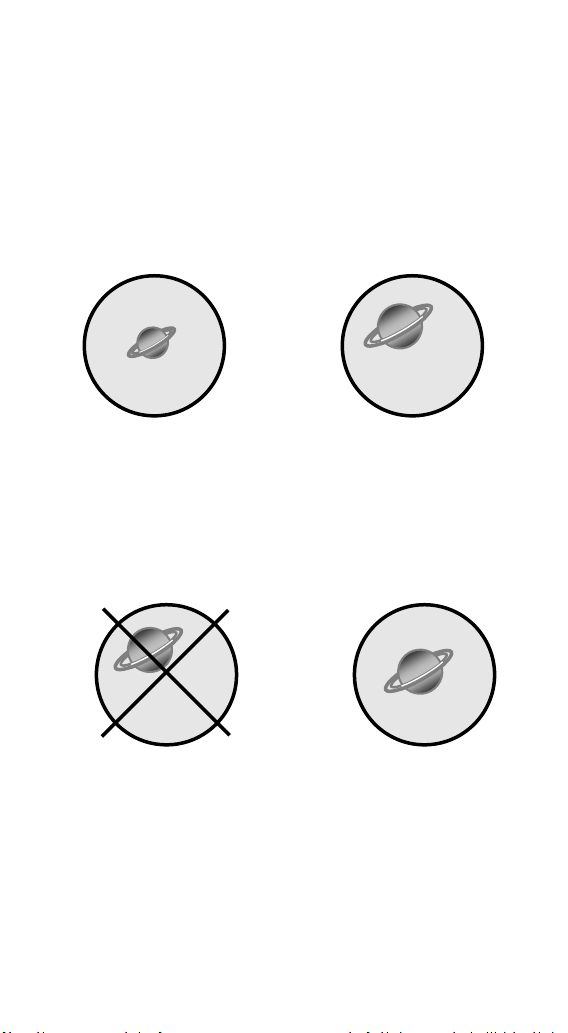
4. The "Zoom Effect"
With the object centered on the eyepiece and focused, by
pressing the [PORT-2] button of the ROTARION REMOTE
CONTROL software, the ROTARION changes the eyepiece
on the [PORT-1] to the eyepiece [PORT-2] with increased
power or magnification.
[PORT-1] [PORT-2]
Now you must focus the telescope again. The observed
image should be larger and have less visual field. Center
the image again in the eyepiece (B).
[PORT-2] Centered NOT OK. [PORT-2] Centered OK.
(B)
Afterwards, you can increase the magnification of your
telescope by changing to the following eyepieces of
smaller number of mm and higher magnification, [PORT-3]
and [PORT-4].
When you perform the object centering procedure on the
eyepiece and focus before changing to the next eyepiece,
the object will appear in your field of view.

58
NOTE: The size of the image of the objects in your eyepiece
is a function of the magnification of your telescope. The
magnification formula X equals the focal length of your
telescope divided by the number in mm of the eyepiece.
Example: for power calculation, magnification or
magnification X must know 3 things about your telescope
• The diameter of your telescope D = 152mm = 6 "*
• The focal length of the telescope F = 1000mm.
• The number in mm of the eyepiece = 20mm.
Magnification X = Focal length / mm of eyepiece
Therefore, if we use a telescope with 1000mm focal length
and a 20mm eyepiece.
Magnification X = 1000mm / 20mm = 50X
Which would give us 50 magnifications, but if you change
to a 10mm eyepiece it would be 100 magnifications.
There is a maximum limit of magnification in your
telescope due to optics and atmospheric conditions or
"seeing". If you increase too much power or magnification
the image of the object in the eyepiece will appear faint
and blurred. The maximum magnification limit of your
telescope is calculated:
Max X = Diameter in inches * 50
If you use a telescope with a diameter of 6 inches:
Magnification Max = 6 "* 50 = 300X
That is, the maximum magnification for this telescope is
300X.
* For your information, the conversion from inches to mm
is: 1" inch = 25.36mm.
59
5. The "Finder Effect".
If the image of an object moves or trails through the field
of view (A) of the eyepiece due to mount tracking problems
or because the telescope has not been set correctly and
finally disappears from the field of view (B), you can re-
relocate the object by pressing [PORT-1] to change to the
eyepiece with the largest number in mm, the lowest power
or magnification and greater field of view (C).
(A) (B)
(C) (D)
Once the object has been relocated, remember to center
the image in the eyepiece (D) before making the change to
an eyepiece of smaller number of mm, greater power or
magnification and smaller field of view. This ensures that
the object will appear in the field of view of the next
eyepiece.
60
D-Additional Product
Information
Please read the following instructions and information.
1. Product Compliance Information
The AstronSCIENTIFIC S.L. corporation with address at
Marti i Julia 6-8, Barcelona 08834 Spain E.U. has certified
this product with the IEC 61010-1 Norm for Safety
requirements for electrical equipment for measurement,
control, and laboratory use in compliance with the Bureau
Veritas Consumer Products Services Germany GmbH
corporation based at Türkheim, Germany.
If the equipment is used in a manner not specified by the
manufacturer, the protection provided by the equipment
may be impaired.
The CE Certificate Product Marking:
Instruction Manual Version:
Rotarion EyepieceWheel & Rotarion Remote
Control V:1.0 CE

61
2. Service, Maintenance, Cleaning,
Disposal, Serial Number, and
Dealer:
Car adapter fuse:
• 4 Amp 12V 6.3x32mm, fast acting.
• To replace it, unscrew the tip and replace.
Operating environmental conditions:
• Max. 2000m. / 0-40
o
C / 32-104 Fahrenheit and
80% humidity.
Degree of Protection IEC 60529:
• Not applicable.
The Power Supply:
• Input: 100-240Vac; 50/60Hz; 0,55A
Output: 12Vdc; 2A; Limited Power Source
• Disconnect the Power Supply unit from the
ROTARION. The Power Supply unit must be
freely accessible and must not be covered nor
obstructed for disconnecting the ROTARION
when needed.
• Only use the supplied Power Supply unit.
• Please compare the rating plate of the Power
supply unit with the local mains voltage and
frequency.
Maintenance technical data:
• Maintenance free.
Cleaning:
• Use a soft cloth without liquids.
62
Disposal:
•
• Equipment with this symbol shall not be
disposed of together with household or
commercial waste.
• Please find out about separate disposal at your
regional offices.
• The directive 2012/19/EU on waste electrical
and electronical equipment (WEEE) is applicable
in the European Union member states.
Serial Number (or PN) :_____________________________
Dealer: ________________________________________
Date: __________________________________________

63
E-Warranty
The warranty is extended to all countries where this
product is distributed by AstronSCIENTIFIC S.L. or by a
distributor assigned by it. This warranty is subject to the
legal provisions of each country.
3. Warranty period
The Warranty period is 2 years from the date of the sales
invoice issued by AstronSCIENTIFIC S.L. or by the
distributor authorized by AstronSCIENTIFIC S.L.
4. Warranty Coverage
The conformity of the product is warranted according to
the use for which it is intended.
Within the warranty period, we will remedy any defect in
the operation of the product due to its manufacture,
whether repairing, replacing parts or providing a new
product, provided that the option chosen is feasible and
not economically disproportionate according to the
criteria of AstronSCIENTIFIC S.L.
For any of the three options, repair, replacement of parts
or exchange for a new product, the consumer must go to
the authorized distributor of AstronSCIENTIFIC S.L. where
the product was purchased.
5. Warranty Nullity
This warranty will not be valid in the following cases:
Misuse, improper use, neglect, accident, or deterioration
of the product due to failure to comply with the warnings
and restrictions contained in this Instruction Manual or in
the operating instructions provided by AstronSCIENTIFIC
S.L.

64
External agents such as water or other harmful chemicals,
obstructive or corrosive.
Likewise, faults or malfunctions caused by incorrect
voltages and electrical installations will not be covered by
this guarantee.
This warranty does not cover any product that has been
altered or repaired by any person other than
AstronSCIENTIFIC S.L. repair personnel, or any product
whose serial number, model number or identification has
been removed, defective or altered.
AstronSCIENTIFIC S.L. shall not be liable for any indirect,
special, incidental, or consequential damages related to
the sale or use of the product.
65
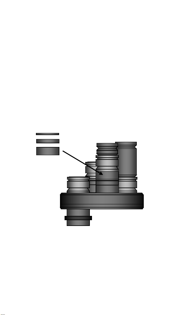
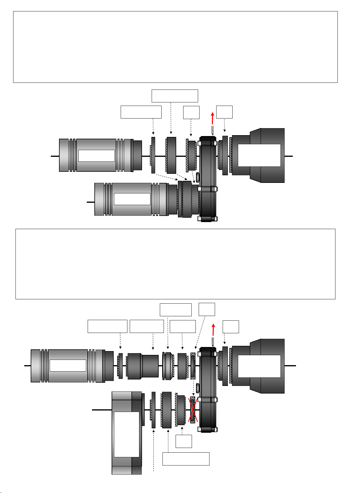
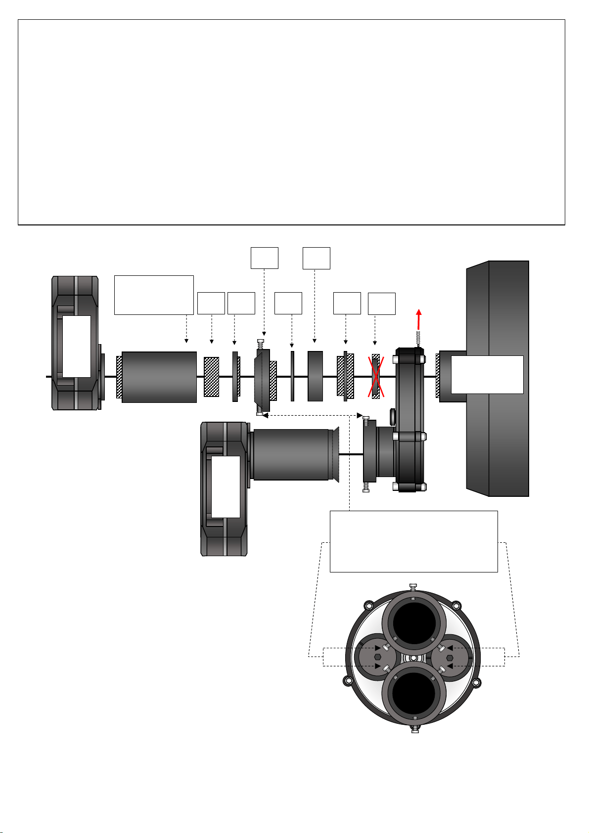
3.2. Rotarion CAM Kit & Rotarion Remote Control PRO software.
1.- Remove (unscrew) the Click-Lock clamps including all extenders/spacers, and without removing the four black
color thread adapters Part# 4.1 “SC -to- T2”.
2.- Unscrew the 2 screws (A) located on the bottom of the ROTARION with the included Allen wrench and remove the SMALL handle (B)
carefully.
(B)
(A)
3.- Introduce the NEW 2 stainless steel Allen screws (C) and screw the 2 Nylon head nuts (D) using the supplied Allen wrench and the Nº
10 wrench. Screw the 2 nuts tightly.
(D)
(C)
STEP 1 - ROTARION CAM Kit
HOW TO REMOVE ROTARION STAINLESS STEEL HANDLES
66
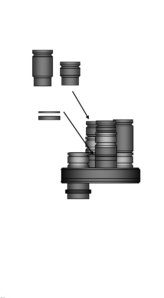
4.- Unscrew the 3 screws (E) located on the bottom of the ROTARION with the included Allen wrench and remove the LARGE handle (F)
carefully.
(F)
(E)
5.- Introduce the NEW 3 stainless steel Allen screws (G) and screw the 2 Nylon head nuts (H) using the supplied Allen wrench and the Nº
10 wrench. Screw the 3 nuts tightly.
(G)
(H)
67
Group #3
2” Focuser
Group #2
SC Thread
Group #1
Tele Vue “IS”
Group #1
Tele Vue “IS”
Group #2
SC Thread
Group #3
2” M48x0.75
2.3
3.6
4.1
3.2
3.3
3.4
3.5
3.7
3.8
1.2
1.1
3.10
3.11
2.2
2.1
STEP 2 - ROTARION CAM Kit
Telescope System Adapters Map
Group #4
T2 M42x0.75
4.4
3.2
3.4
3.7
4.1
4.3
4.2
2.4
4.1
3.2
3.3
3.4
3.5
3.7
3.8
68
TO
TELESCOPE
TO
CARROUSEL
Adapter's
total
length
(including
male
threads)
Male
Threads
Telescope's focal path
length used in mm =
Adapter's total length -
Male threads hidden
when assembled with
other parts
Rotarion' carrousel
has a 1mm available
inner cylinder space
for Adapter's non-
threaded parts
Total
telescope's
focal
path
length used
in mm
YES - 1.1 060504a 1
M1108
(TVO IS female -to- SC male)
To be mounted instead of already mounted Part#3.10 2” barrel, SC male -to- M48 female (remove barrel locking-screw
first),
use the M1108 to thread the Rotarion to Tele Vue IS telescopes
14,85 7,5 7,35 N/A 7,35
- YES 1.2 060507 2
M1240
(SC male -to- TVO IS male)
Remove the already mounted parts# 4.1 SC male -to- T2 female adapters in Rotarion’s carrousel,
use M1240 for Tele Vue “Large Field Corrector” or any other Tele Vue "IS" parts and optics in Rotarion carrousel side
20,3 6 14,3 -1 13,3
- YES 2.4 2 M48 male -to- SC female
Follow assembly instructions of GROUP #3,
to be mounted in part# 3.5 M48 Rotating camera adapter
instead of part# 3.6; use it for large camera sensors assemblies
15 5 10 N/A 10
YES - 2.1 1
SC Telescope female
(thread in Rotarion’s telescope side)
First lose 2" barrel locking-screw,
second unscrew and remove the part# 3.10 2” barrel, SC male -to- M48 female
N/A N/A N/A N/A N/A
- YES 2.2 4
SC Telescope female
(thread in Rotarion’s carrousel)
Remove the already mounted parts# 4.1 SC male -to- T2 female adapters in Rotarion’s carrousel N/A N/A N/A M/A N/A
- YES 2.3 060505 2
SC male -to- SC male Remove the already mounted parts# 4.1 SC male -to- T2 female adapters in Rotarion’s carrousel 12,4 11,4 1 -1 0
- YES 2.4 2 M48 male -to- SC female
Follow assembly instructions of GROUP #3,
to be mounted in part# 3.5 M48 Rotating camera adapter
instead of part# 3.6; use it for large camera sensors assemblies
15 5 10 N/A 10
YES - 3.10 060120 1
2” barrel
(SC male -to- M48 female)
Already mounted in Rotarion; to be use in any 2” telescope focuser,
verify that part# 3.11 2” barrel extender, M48 male -to- M48 female
is already mounted
36,9 7,9 29 N/A 29
YES - 3.11 060101 1
2” barrel extender
(M48 male -to- M48 female)
Already mounted in Rotarion in part# 3.10 2” barrel, SC male -to- M48 female,
to be use in any telescope 2” focuser
39 9 30 N/A 30
- YES 3.2 100500 2 SC male -to- M48 male
Remove the already mounted parts# 4.1 SC male -to- T2 female adapter in Rotarion’s carrousel 11,9 10,9 1 -1 0
- YES
3.3 2 M48 female -to- M48 female To be mounted in parts# 3.2 SC male -to- M48 male 7,5 0 7,5 N/A 7,5
- YES 3.4 2 M48 0,5mm ring Optional, if need it, to align locking screws of parts# 3.5 M48 Rotating camera adapters 0,5 0 0,5 N/A 0,5
- YES
3.5 2 M48 Rotating camera adapters
First remove the 3 locking-screws and the inner male part;
second thread in parts# 3.3 M48 female -to- M48 female
;
third align both adapters so 2 of the locking-screws face to the other adapter’s 2 locking-screws,
fourth, if need for screws alignment, use part# 3.4 M48 0,5mm ring
12 4 8 N/A 8
- YES 3.6 2 M48 male -to- M48 male
To be mounted in part# 3.5 M48 Rotating camera adapters,
to mount M48 large-sensor cameras
7,5 7,5 0 N/A 0
- YES
3.7 2 M48 length 5mm spacers/extenders
Optional, if need it, to be mounted in part# 3.6 M48 male -to- M48 male,
to para-focalize focus positions among camera sensors in a two-camera setup
9 4 5 N/A 5
- YES 3.8 2 M48 length 10mm spacers/extenders
Optional, if need it, to be mounted in part# 3.6 M48 male -to- M48 male,
to para-focalize focus positions among camera sensors in a two-camera setup
13 3 10 N/A 10
- YES 4.1 100106 4 SC male -to- T2 female Already mounted in Rotarion’s carrousel 7 6 1 -1 0
- YES 4.2 190201 2 T2 aluminum caps
To be threaded in already mounted part# 4.1 SC male -to- T2 female adapters in Rotarion carrousel
to close unused Rotarion’s carrousel positions
5,5 4,5 N/A N/A N/A
- YES
4.3 2 T2 male -to- T2 male To be threaded in already mounted part# 4.1 SC male -to- T2 female in Rotarion carrousel 11 11 0 N/A 0
- YES 4.4 2 M48 male -to- T2 male
Follow assembly instructions of GROUP #3,
to be mounted in part# 3.5 M48 Rotating camera adapter for T2/M42 small-sensor cameras
10 4+4 2 N/A 2
4
2” 24TPI
M48x0,75mm
M42x0,75mm
GROUP#
TELESCOPE SYSTEM
THREAD
TELE VUE IMAGING SYSTEM (IS)
SC TELESCOPE SYSTEM
2” SYSTEM
with M48 Rotating camera adapters
for large camera sensors
T2 SYSTEM
with M48 Rotating camera adapters
and M42 reducers
for small camera sensors
3
UNITS
ADAPTERS
STEP 3 - ROTARION CAM Kit
Telescope System Adapters
ADAPTERT'S OPTICAL PATH LENGHTS
ROTARION SIDE
PART#
COMMENTS
DRAWING#
2”9/16 24TPI
1
2
69
STEP 4.A - ROTARION CAM Kit application example:
Small Sensor DSO Chrominance & Luminance (25% faster than traditional RGB+L)
Equipment Setup: Tele Vue IS telescope + Rotarion CAM + 2x NPR-1073 & TRG1072 + Camera Atik 490 EX Mono &
Camera Atik 490EX Color
**Note: Example configuration drawing only. Additional spacers/extenders may be necessary between the NPR-1073 or LCL-1069 and the camera
depending on the chip to surface plate dimension of the camera. Consult the telescope operating guide for details.
Group #1
Tele Vue “IS”
490EX Color
490EX Mono
1.1
1.2
**TVO NPR-1073
TVO TRG 1072
STEP 4.B - ROTARION CAM Kit application example:
DSO (RGB+L) with Reducer & PLANETARY with PowerMate
Equipment Setup: Tele Vue IS telescope + Rotarion CAM + NPR-1073 and TRG1072 and Camera Atik ONE with filter
wheel (RBG+L) + PowerMate and PTR 1250 and Camera Atik 490EX Color
**Note: Example configuration drawing only. Additional spacers/extenders may be necessary between the NPR-1073 or LCL-1069 and the
camera depending on the chip to surface plate dimension of the camera. Consult the telescope operating guide for details.
Group #1
Tele Vue “IS”
490EX Color
1.1
1.2
**TVO NPR-1073
Atik
One 9.0
mono
with
filter
wheel
RGB+L
4.1
Click-Lock
PowerMate
TVO PTR-1250
Spacers
70
TVO TRG 1072
STEP 4.C - ROTARION CAM Kit application example:
Large Sensor Chrominance & Luminance (25% faster than traditional RGB+L)
with SCT Corrector II -0.63x and M48 Camera rotating adapters [3.5]
Equipment Setup: SC telescope + Rotarion CAM + 2x Starizona Corrector II -0.63x + Camera Moravian G3 Mark II
Mono & Moravian G3 Mark II Color
*Note: Using in the imaging assembly M48 Rotating camera adapters [3.5], and other M48 parts (normally with inner diameter 44mm) may cause
very small vigneting in full-frame sensors, to be corrected by taking “flats”.
**Note: Example configuration drawing only. Additional spacers/extenders may be necessary between Corrector and camera and between SCT
and Rotarion. Consult the telescope operating guide for details.
***Note: the locking screws of the M48 Rotating camera adapters [3.5] have to be aligned as seen below; to do so, you must remove all 3 locking
screws before screwing the M48 Camera Adapter body parts, use optionally the 0,5mm rings [3.4] to achieve locking-screws alignment.
Moravian G3
Mark II Color
3.2
3.3
3.4
3.5
3.7
4.1
3.6
*** Locking-screws must be aligned in
M48 Rotating Camera Adapters [3.5],
remove locking-screws before screwing
M48 body part, use optionally 0,5mm
rings [3.4] for alignment.
Group #2
SC Thread
Starizona SCT
Corrector II
-0.63x
Moravian G3
Mark II Mono
71
STEP 5 - ROTARION CAM Kit
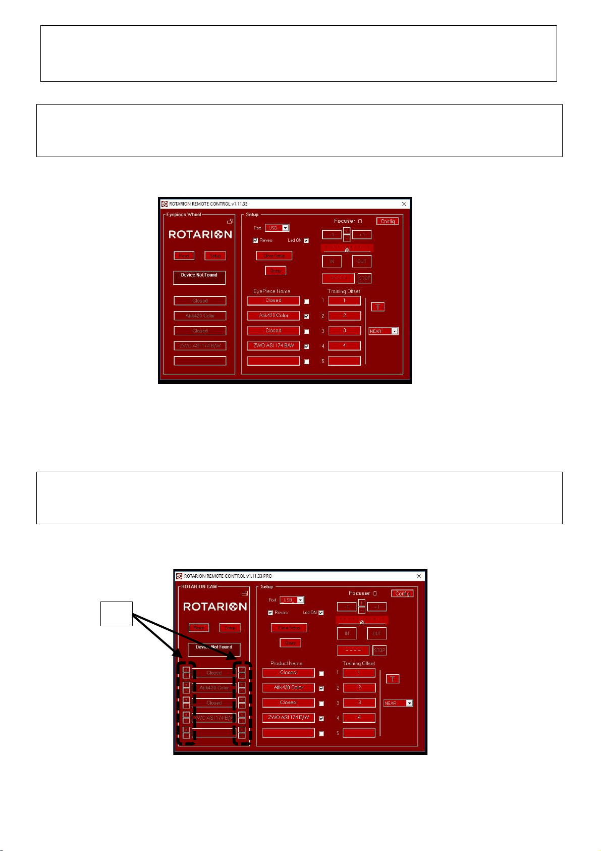
ROTARION Remote Control PRO software
1.- Open your ROTARION Remote Control software (if you have not installed it yet, proceed with the installation
now; use the ROTARION Remote Control software Instruction Manual included in the ROTARION The Eyepiece
Wheel box).
2.- Connect the ROTARION PRO USB key. Now the micro-tuning adjustment keys [A] will appear in the software
interface. See next image and compare it to previous image.
(A)
72
3.- Click on the micro-tuning adjustment keys [A] to adjust the angular backlash cause by either heavy camera
loads, or unbalance camera loads.
Please note that there are 4 micro-tuning keys [B] for each ROTARION position.
Each side keys (2 keys per side, and identified by “+” or “-“ symbols) correspond to either turning the ROTARION
carrousel to the left or to the right.
On same side keys, you may adjust more backlash or less backlash using the “+” or “-“ keys.
Also observe that each side keys [B] are only activated and available when the ROTARION carrousel turned from
that specific side (left or right turn). So, if you are clicking on the right-side keys and you cannot observe
carrousel movement, click on the other left-keys and you will see movement.
(B)
4.- Use the 4 red dials [C] on the ROTARION carrousel and the black dial [D] in ROTARION body closes to the 2”
barrel as reference points for the micro-tuning adjustments.
4.- Note:
• Micro-tuning backlash adjustment is a trial and error procedure, that is, you may have to adjust several
times to achieve perfect on-axis results on each position for each left/right turns.
• Once adjusted the micro-tuning, the system memorizes the individual backlash for every position,
therefore you can remove the ROTARION PRO USB key after.
• Although the ROTARION can be powered only by the USB wire, we recommend to plug-in the external
power, either by using the 12Volt car wire or the international power supply AC/DC wire.
(D)
(C)
73
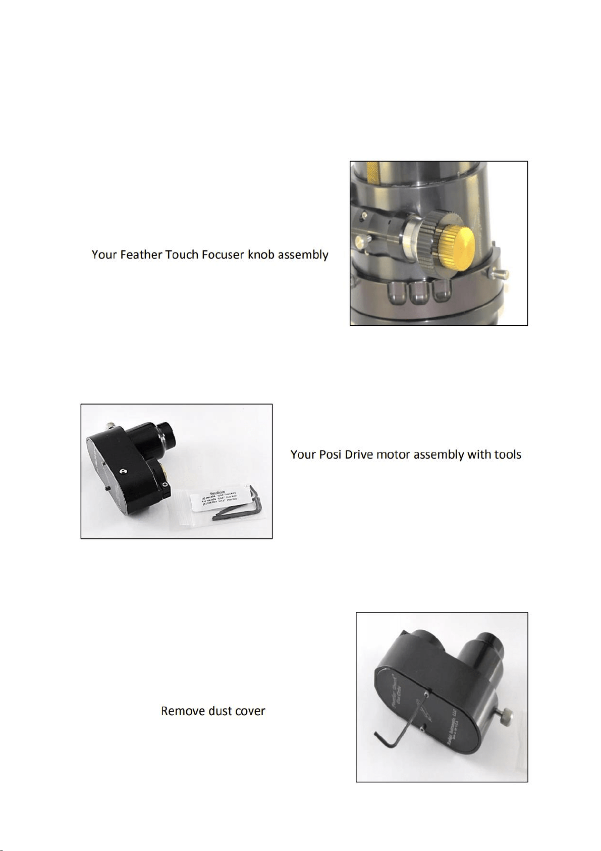
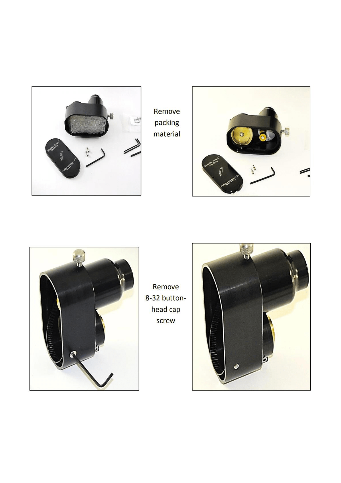
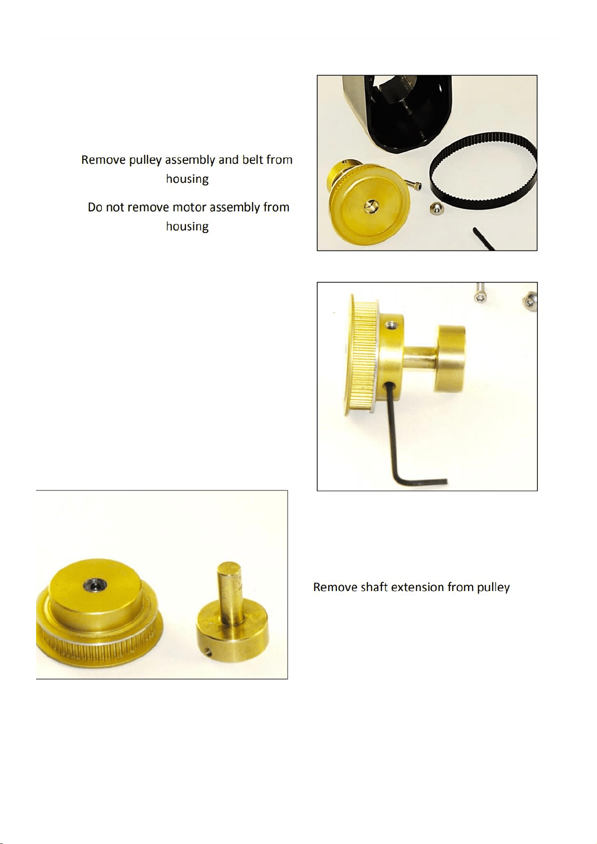
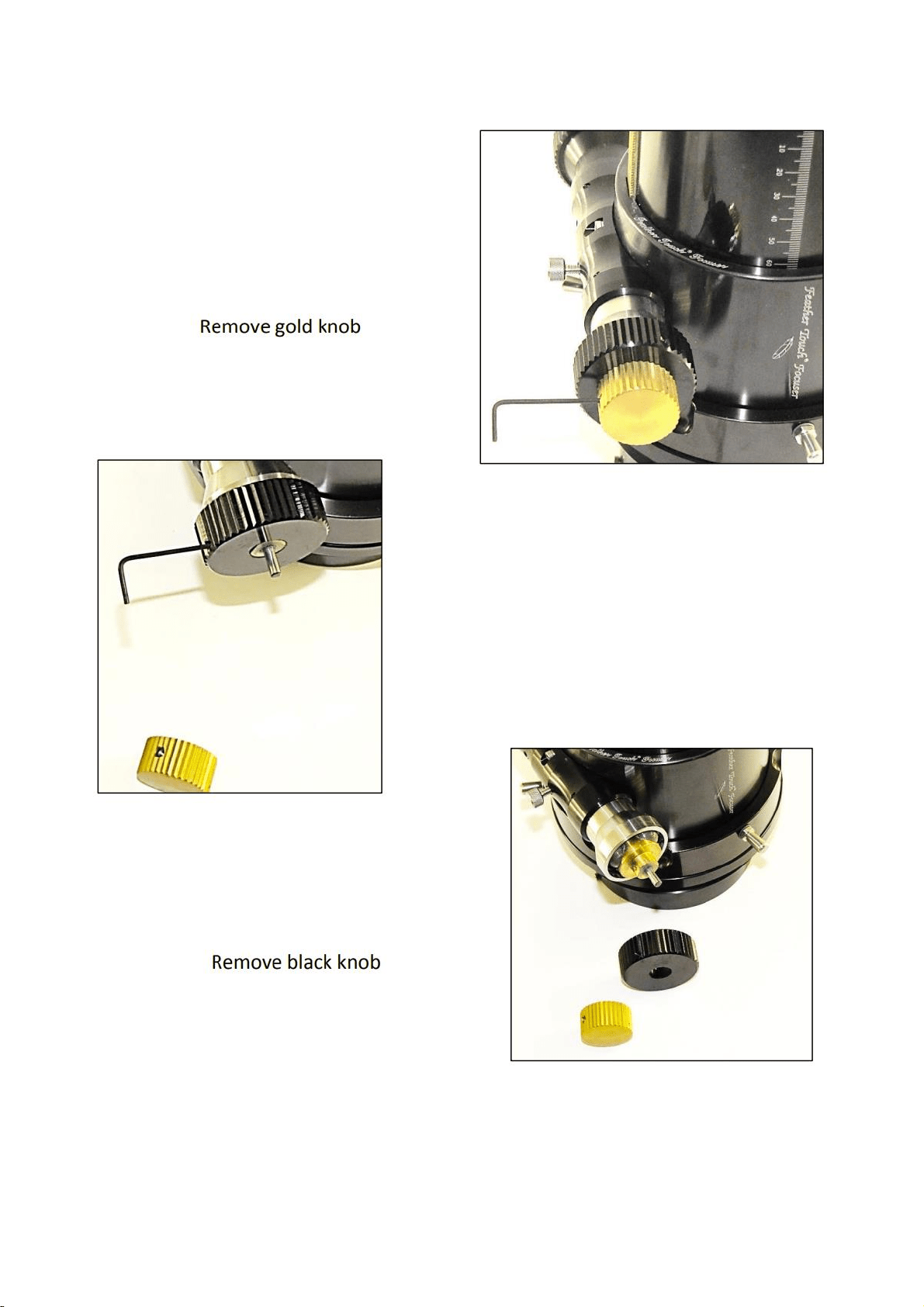
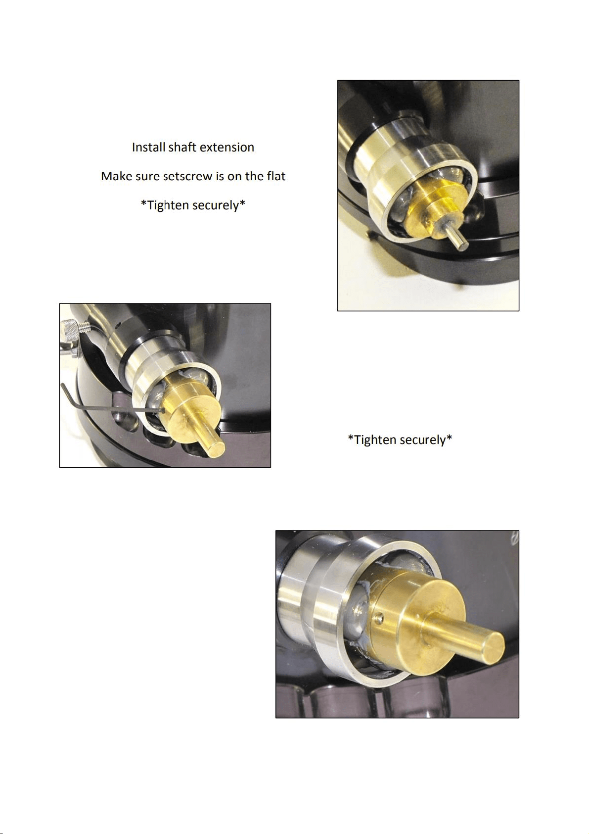
4.1. TV-85 Focuser & 4.2. StarLight Motor Focuser SI-PDMS--
POSI DRIVE MOTOR SYSTEM
The Posi Drive Motor System for the Feather Touch focuser can lift in Excess of 56 pounds. This motor system
attaches to the pinion shaft and not the reduction assembly which eliminates any slip and offers precise
repeatability with heavier payloads. The PDMS has 2.3 microns per step(.00009") which is 11,400 steps per inch.
The PDMS-FT motor comes standard with an over-ride to allow for manually focusing with the COARSE focus
knob. The PDMS motor has the thermistor built onto the motor circuit board for temperature compensation.
74
75
76
77
78
79
80
81
82

83
4.3. Rotarion Autofocus
84

85
Congratulations on your purchase of ROTARION
AUTOFOCUS!
ROTARION AUTOFOCUS is designed and
manufactured to be used for daytime terrestrial
observation and for nighttime astronomical
observation.
ROTARION is a unique device, patented in the
European Union and the United States, to be used
with any telescope with a 2" focuser and four of your
favorite 1.25" eyepieces.
For the first time, you can change the power or
magnification of your telescope with just a simple
click and the new chosen lens will focus
automatically when connecting your ROTARION and
ROTARION REMOTE CONTROL software or
ROTARION HAND CONTROL to the ROTARION
AUTOFOCUS found in this box.
ROTARION makes the eyepiece change easy.
Automatic, quick, precise and without touching the
telescope avoiding disturbances in the positioning or
misalignment of the optical axis between eyepieces.
No more searching in the dark for your next
eyepiece!
The automatic eyepiece change allows you to
adjust the correct magnification on your telescope
by increasing or decreasing the focal length of the
eyepiece used, the "zoom effect".
Re-locate lost objects out of the field of view due
to improper alignment or poor tracking of the

86
telescope. Quickly change to your largest eyepiece in
mm to maximize your field of view and re-locate. All
with a simple Click!
The ROTARION AUTOFOCUS connected to the
ROTARION REMOTE CONTROL software includes an
easy Training Procedure (“T” Key) so it can learn your
variable focal offsets among your optics mounted on
the ROTARION. The built-in algorithm calculates for
you each time you order a lens change, the needed
focus correction to make your optics par-focal, and it
is compatible with many market available motor
focusers.
ROTARION AUTOFOCUS is a device of the highest
quality, designed and manufactured in BARCELONA
with the latest state-of-the-art techniques and the
best materials and components from the U.S.A.,
Japan, and Germany.
First, read this instruction manual thoroughly and
then follow the assembly instructions step-by-step.
If you follow the instructions correctly, even if it is
initially laborious, the use of ROTARION AUTOFOCUS
is very simple and easy.
All this to offer you many hours of enjoyment
observation, and satisfaction with your telescope.
Maximum quality, universal, versatile, and easy
to use, ROTARION continues our corporate mission:
AstronSCIENTIFIC
Astronomy Made Easy

87
In the Box
• ROTARION AUTOFOCUS with female SUBD-9
connector cable labeled "A", compatible
with Moonlite or Robofocus stepper motors.
• Adapter wire A01 for Orion, TeleVue motor
• Adapter wire A02 for JMI motor
• Adapter wire A10 for FeatherTouch MSM20
motor
• Adapter wire A11 for Feather Touch HSM20
motor
• Plastic zip strap
• Double sided adhesive tape
• Instruction Manual

88
System Requirements
• It is necessary to have an ROTARION
EyepieceWheel to use the ROTARION
AUTOFOCUS.
• In addition, a telescope with a motor
coupled to the focuser. The motor can be:
Stepper (Moonlite, Starlight FeatherTouch)
or DC (Orion, TeleVue, JMI)
• Specific wire to connect to the focusing
motor included.
• ROTARION REMOTE CONTROL Software
included with your ROTARION, a PC
Windows XP / Vista / Win7 / Win8
compatible is required. You will also need a
Serial port on your computer
• Optionally, you can use the ROTARION HAND
CONTROL connected to the ROTARION, for
the control of the ROTARION AUTOFOCUS,
ideal for field use without a PC or computer.

89
Index
A-Introduction
B-Characteristics
C-Connecting the focuser’s motor
D-Connecting the ROTARION AUTOFOCUS
to your ROTARION EyepieceWheel
E-Config screen
• Mini Control
• Backlash
• Min Speed
• Max Speed
• Power Moving
• Power Stopped
• Max Position
• Motor Type
• Wiring (Motor model)
• Revers
• Selector ResetPos
• Position Reset
F-Control Screen
• Focuser Led
• Auto Advance keys
• Ruler
• Keys [IN] / [OUT]. Manual Advance
• Actual Position
• STOP key
• Focuser Training Offset Panel
• TRAINING key

90
G-Preparation & Training
3. Motor Type
4. Motor Model
5. Preparation
a. Atmospheric Factors & Focusing
b. Motor Focuser Systems
c. Crayford and Rack-and-Pinion Focusers
d. Other Focusers
6. TRAINING procedure
3.1. Near Object
3.2. Far Object
3.3. Very Far Object
3.4. TRAINING Completed
H-Ready for Observation
1. Observing an Object
2. Changing to a New Object
3. Resetting the Focuser
I-Additional Product Information
1. Product Compliance Information
2. Service, Maintenance, Cleaning, Disposal, Serial
Number, and Dealer
J-Warranty
4. Warranty Period
5. Warranty Coverage
6. Warranty Nullity

91
A-Introduction
The ROTARION AUTOFOCUS of
AstronSCIENTIFIC is a telescope par-focal system
and focus controller, which works alongside the
ROTARION EyepieceWheel automatic eyepiece
exchanger. It is designed to control the motor
that is commonly found in telescope focusers,
whether DC type (DC motor) or Stepper type
(stepper motor).
You can quick-change eyepieces and focus
automatically. All with a single Click!
B-Characteristics
• Connects directly to the ROTARION
EyepieceWheel automatic eyepiece
exchanger.
• Obtains energy from the ROTARION
EyepieceWheel itself.
• Compatible with any DC focusing motor that
uses 5 to 12V such as Orion, TeleVue, JMI,
etc.
• Compatible with Moonlite, Robofocus,
Feather Touch stepper motors.
• The output is a 9 pin SUBD female connector
compatible with Moonlite motors. A specific
cable is required for all other motors.
• Red LED indicator of focuser movement.

92
• Adjustable speed control and PWM
frequency control to optimize performance
with your specific motor model.
C-Connecting the Motor
Focuser
The ROTARION AUTOFOCUS output is a female
SUBD-9 connector labeled "A", compatible with
Moonlite or Robofocus stepper motors.
To connect it to another motor, you need a
specific adapter cable for the motor. Various
types of cables are available from
AstronSCIENTIFIC distributors.
The adaptor cables found in the box are:
A01: for DC motor ORION, TeleVue
A02: for DC motor JMI
A10: for stepper motor Feather Touch MSM20
A11: for stepper motor Feather Touch HSM20
These cables have a SUBD-9 male connector on
one end and a specific connector for the motor
focuser on the other end.
Attach the connector of the ROTARION
AUTOFOCUS marked "A" to the motor cable
that corresponds to your focuser marked "Axx".
Connect the other end of the motor cable to
your motor focuser.
93
D- Connecting the
ROTARION AUTOFOCUS
to your ROTARION
EyepieceWheel
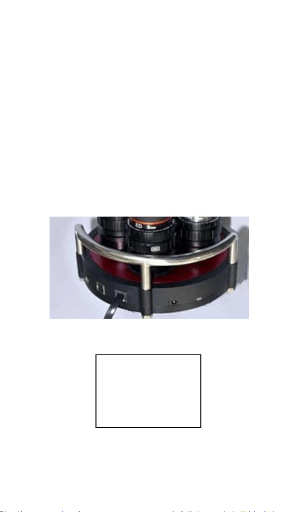
The second ROTARION AUTOFOCUS cable must
be connected to the ROTARION EyepieceWheel
Focuser port
(5). Although the connector looks
like a mini-USB, it is a data and power cable.
ROTARION EyepieceWheel
Connectors
5
4
3
2
1
1
Power input
2
Serial Port
3
USB Port
4
Status Led
5
AUTOFOCUS
Port

94
Connect the Serial Port
(2) to the PC/computer
or ROTARION HAND CONTROL. The RED LED in
the ROTARION AUTOFOCUS box should blink 3
times. If not verify the power supply in the
ROTARION and also verify the micro-USB cable
connector from the ROTARION AUTOFOCUS to
the ROTARION.
Currently the USB port
(3) is operative for the
ROTARION EyepieceWheel only. ROTARION
AUTOFOCUS control via USB port is not
available yet.
Now let's get to know the ROTARION REMOTE
CONTROL software that simultaneously
controls the ROTARION EyepieceWheel and the
ROTARION AUTOFOCUS.
In
blue color we have marked the legends
referring to the basic operation of the
ROTARION EyepieceWheel, and in
green color
the legends referring to the ROTARION
AUTOFOCUS.
CAUTION: Although the Focuser port's power
and data connector (5) has the form of a mini
USB, IT IS NOT A USB CONNECTOR.
Never connect a mini-USB connector from
another device. It could seriously damage both.
95
n
E-Config Screen
Select the [Config] / [Control] button
(23) to
access the ROTARION AUTOFOCUS configurable
parameters.
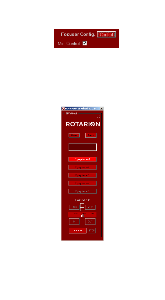
Mini Control
(31)
When you activate this box and
the Setup screen
(7) or (11) is
closed, the ROTARION
AUTOFOCUS mini-control
panel will appear at the
bottom of the
ROTARION
REMOTE
CONTROL
main screen.
14
6 7 8 9 10 11 12 13
17 18
23
32
33
34
35
36
37
38
96
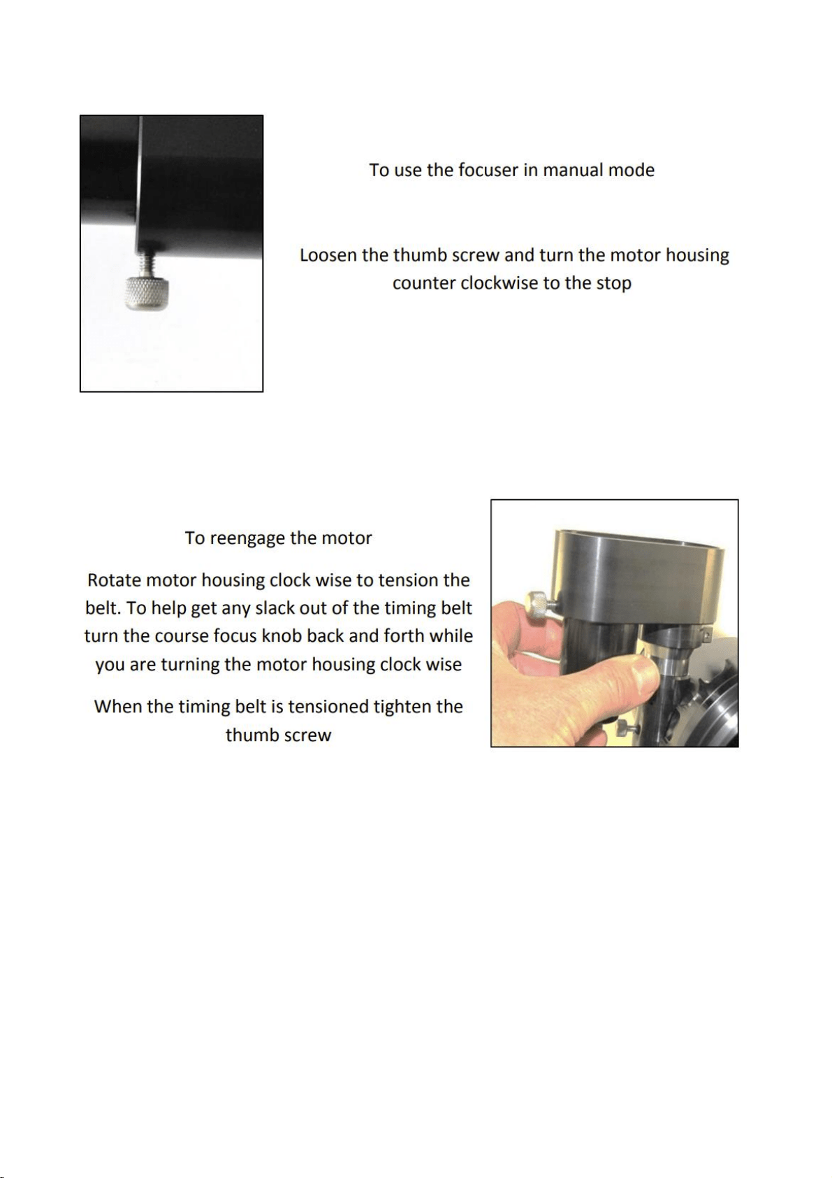
Backlash
(32)
The Backlash is a slack in the focuser mechanism
that is noticed during movement. That is,
depending on the focuser and after moving in
one direction, by reversing the motion a
substantial distance the motor may have to
move the before the focuser begins to move.
To compensate it, the AUTOFOCUS can add
additional steps to the distance each time the
direction of rotation is reversed. The default
value is 0
Min Speed (33)
Specifies the minimum speed at which the
motor will move, in milliseconds / step. Value
from 1...99 ms / step
Max Speed (34)
Specifies the maximum speed at which the
motor will move, in milliseconds / step. Value
from 1...99 ms / step
In stepping motors, the movement starts at Min
Speed and is increased by a ramp to Max Speed.

97
In DC motors, there is no speed increase by
ramp. Min and Max Speed values are the same.
Power Moving
(35)
The Power Moving is the% of the total power
(PWM) that is applied to the motor when it is
moving.
Range 0...100%
Power Stopped
(36)
Power Stopped is the % of the total power
(PWM) that is applied to the motor when it is
stationary.
Value from 0...100%
In a stepper motor, the Power Stopped allows
the motor to maintain a certain torque when it
is at rest. If the motor has a gearbox, you can
leave it at 0%; In this way you avoid the heating
of the motor.
In a DC motor, no power is applied while at rest
because it would move. However, it is used to
brake the engine and stop it in the shortest
possible time (shorter distance).
Note: As the speed is expressed in ms /
step, the value for the minimum speed
must be greater than the value for the
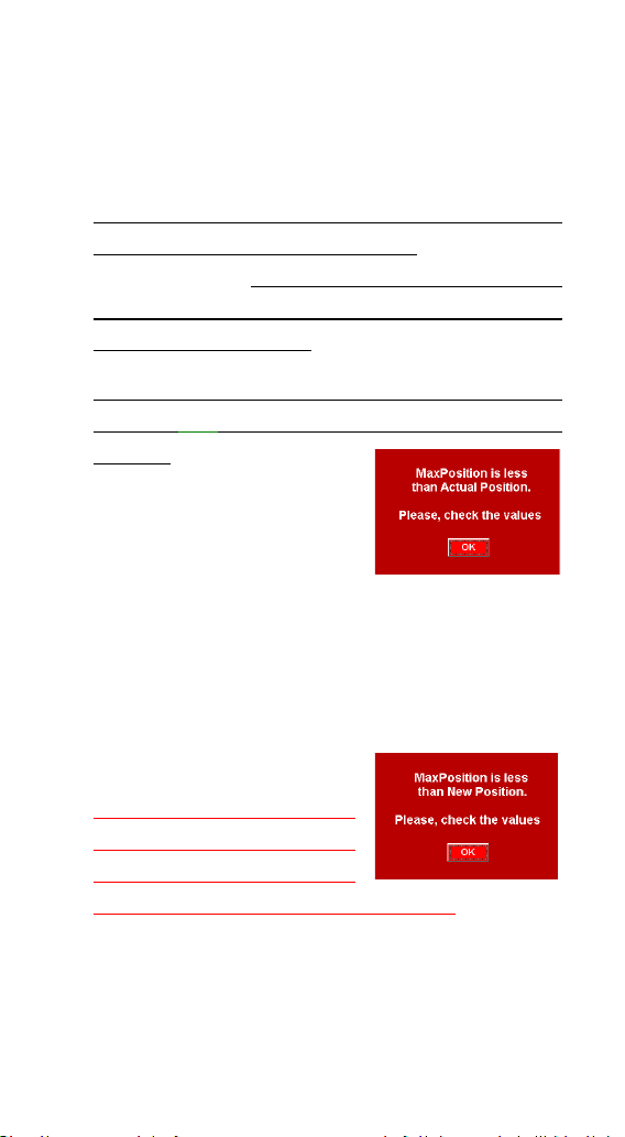
98
Default is 0% for stepper motors and 100% for
DC motors.
Max Position (37)
Specifies your maximum focuser range. If this
value is reached the motor stops. Max Position
is 60,000 steps, but you may type a lower value
when finding your specific mechanical focuser
range from IN to OUT.
The minimum value for the Current Position
counter (25) is "0", that is your focuser all the
way IN. Therefore, it is
unable to take negative
values.
The value of Max Position
must be greater than your actual focus
coordinate displayed at the Current Position
counter, and your future position when clicking
the auto advance keys (+10, +100, +1000, etc..).
If any are larger, the upper and lower warning
messages will appear.
Verify if you can increase
your Max Position value
without causing a
mechanical problem in your focuser!
Click [YES] to continue and increase the Max
Position value.
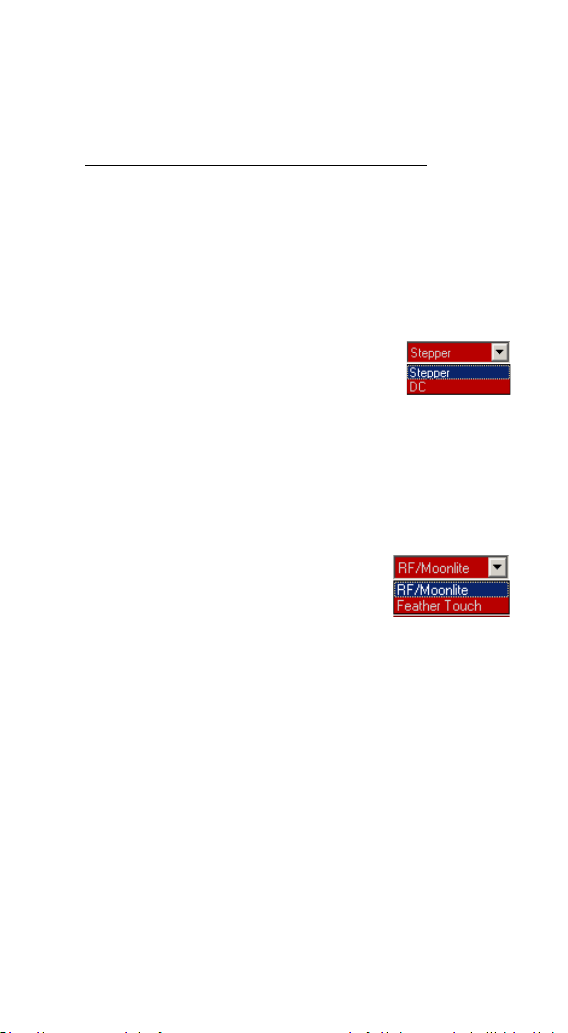
99
Inertia
(38)
Specifies the compensation in number of inertia steps
for DC motors for heavy optical/imaging gear loads.
It is in development. Leave the values at 0.
Motor Type
(39)
You need to identify what type of motor and
model is in your focuser.
Select from the drop-down list
your motor focuser type, which
will connect to the AUTOFOCUS:
Types of motor: DC (direct current), Stepper
(step by step).
Wiring (Motor model)
(40)
Select from the drop-down list
the "model" of motor,
depending on the Motor Type
(39) selected in the previous section. If it does
not match any of the list, choose one that is
compatible.
When selecting the motor model, an automatic
preset of the Speed and Power parameters is
made. It is possible to change these values to
suit the type of motor and / or telescope
focuser.
Motor brands pre-programed:
motor DC: Orion, TeleVue, JMI
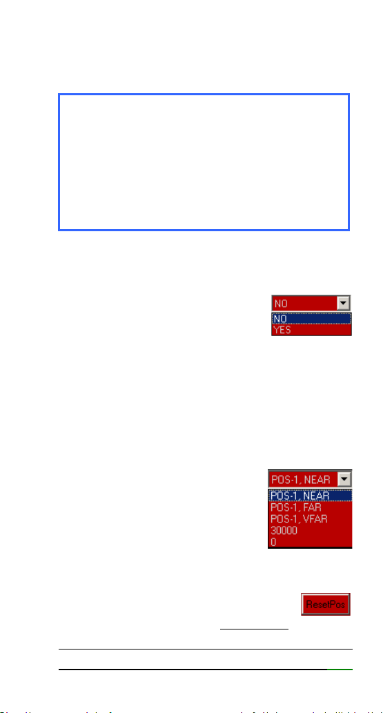
100
motor Stepper: RoboFocus, Moonlite,
FeatherTouch
Revers
(41)
It allows the motor to be turned
in inverted mode, to adjust the
[IN] and [OUT] keys with the
movement of the focuser. See section
(24) [IN]
/ [OUT] Keys
Selector ResetPos
(42)
Select the value from the drop-down list to be
used as the reference value for
the Current Position counter.
See next section.
Reset Position Key
(43)
Pressing this button resets the
Current Position counter. That is, the
telescope user has moved the focuser without
the [IN] or [OUT] or the auto advance keys (21)
Note: Remember that if you have changed
the Speed / Power parameters for one
motor and select another one, default
parameters are loaded. If you then re-select
the motor you had previously, the default
values for that motor are loaded. The
previously changed values are not

101
and the ROTARION AUTOFOCUS has lost your
focuser mechanical coordinate and is not
focusing correctly.
To correct it, the user must synchronize again
the focuser mechanical coordinate with a
previous focused object used during the
TRAINING procedure in the Current Position
counter. To proceed choose one of the
following reference values from the selector
ResetPos (42) drop-down list.
Reference values:
PORT-1 NEAR: Position for NEAR object in
eyepiece PORT-1
PORT-1 FAR: Position for FAR object in
eyepiece in PORT-1
PORT-1 VFAR: position for VERY FAR object in
eyepiece in PORT-1
30000: Intermediate focuser coordinate of
telescope travel. Recommended for
Schmidt Cassegrain and similar
telescopes with internal primary
mirror displacement.
0: Maximum IN (inward) focuser
coordinate. Recommended for
Crayford and rack-and-pinion
focusers found in most refractor and
reflector telescopes.

102
Once you have focus
one of the previous
chosen references
values (PORT-1 NEAR,
PORT-1 FAR,…30000, 0), to the question “Are
you sure?”, click [YES].
Note: You should normally have the
Eyepiece 1 selected and the object well
focused before making a Position Reset.
103
F-Control Screen
Select the [Control] / [Config] key
(23) to access
the AUTOFOCUS Control screen
Focuser LED (20)
LED flashes when the focuser is
in motion.
Auto Advance Keys (21)
When you press the forward
keys, the motor moves the
number of steps indicated
on them.
With the [+] and [-] buttons, you change the
number of steps and the scaling factor of the
ruler
(22).
Focuser Control Screen
14
6 7 8 9 10 11 12 13
17 18 30
23
24
25
26
27
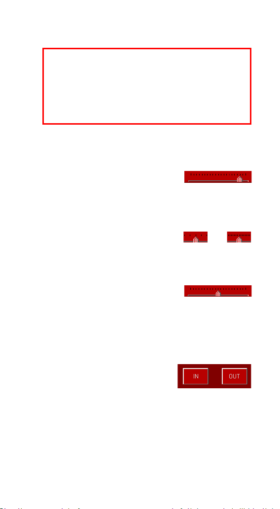
104
Range of steps: ±1, ±10, ±100, ±1000, ±10000
Ruler
(22)
With this ruler you can follow
the movement of the focuser.
The cursor slides under the graduated scale the
number of steps of the focuser motor.
The scale factor is adapted to
the steps that you select using the + or -
buttons.
To center the cursor, click on
the graduated ruler.
[IN] / [OUT] Keys. Manual Advance
(24)
Pressing the [IN] or [OUT]
key causes the motor to
move for as long as you hold
it down.
Usually with the [IN] key you should move the
position of the focuser inwards and use the
[OUT] key to move it outward. If the movement
using the [IN] and [OUT] keys does not match
CAUTION: The ROTARION AUTOFOCUS does
not have the ability to detect when your
focuser has reached the IN or OUT ends.
Damage can occur if you try to go beyond
the mechanical limits of your focuser. Find

105
the direction of the focuser, you can activate
the Revers function
(41).
Current Position
(25)
The Current Position measured in steps of the
focuser appears in this display. Each step in the
OUT direction increases the position, while in
the IN direction decreases it.
STOP Button
(26)
Pressing [STOP] stops/halts any movement of
the focuser. Do it only in case of emergency,
because it will be necessary to resynchronize
the position.
Focuser Training Offset Panel
(29)
In this panel you will find the training offset
values of the focuser for each eyepiece located
in PORT-1 to PO-4.
For each eyepiece 3 different
focusing distances are saved
(offset), which are selected
through the drop-down list
(28)
NEAR: for NEAR objects
FAR: for FAR objects
VFAR: for VERY FAR objects
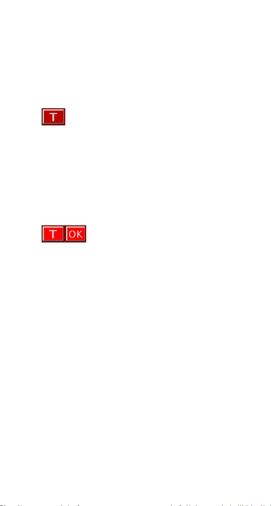
106
By means of the TRAINING Procedure explained
later in this manual, the 3 panels of position of
the focuser are configured.
TRAINING Button
(27)
This button starts the TRAINING
Procedure, which consists of adjusting
the focus for 3 objects, with 3 focus
distances: near, far and very far, and for each of
the eyepieces.
See the TRAINING Procedure chapter later.
When you start TRAINING, the
button lights up and an [OK] button
is displayed beside it, which is used during the
procedure.

107
G- Preparation & Training
When starting up for the first time, you must set
the type and model of motor that corresponds
to your focuser.
1. MOTOR TYPE
Choose the appropriate motor
type from the Motor Type
(39)
list.
2. MOTOR MODEL
Choose the appropriate motor
type from the Wiring
(40) list.
In the ROTARION HAND CONTROL choose the
option
MENU 5. Focus Config MotorTyp < >
In the ROTARION HAND CONTROL choose the
option
MENU 5. Focus Config Wiring < >

108
3. PREPARATION
Before you begin the next Instructional Manual
section “TRAINING PROCEDURE”, please read
the following and follow the indicated
recommendations below.
3.1. ATMOSPHERIC FACTORS & FOCUSING
Local changes in atmosphere factors such as
density, humidity, temperature, and pressure
will decrease focus offset precision calculated by
the “Training Procedure”, as well as changing
viewing locations (altitude, etc.…) with different
atmospheric factors. Therefore, since the
weather conditions can change even in a few
minutes, it may be necessary to fine-focus the
initially proposed ROTARION AUTOFOCUS focus
coordinates.
When you fine-focus one or all eyepieces
mounted in positions PORT-1 till PORT-4 using
the IN or OUT keys or with the Auto Advance
Keys (21), the system will memorize the new
focus offsets reproducing later excellent
autofocus results.

109
3.2. MOTOR FOCUSER SYSTEMS
The more mechanically precise is your focuser is,
the better ROTARION AUTOFOCUS
repeatability, and the better autofocus results
you will get. As an example, a standard Crayford
focuser can be less precise (due to shaft
slippage, etc..) than a focuser with rack-and-
pinion.
The more mechanically rigid the attachment is
your motor to your focuser, the better focusing
results your will get too. A direct motor to
focuser connection without elastic parts or
brackets that have flexure it produces better
repeatability.
A stepper motor is highly recommended due to
the motor type inherent precision over a
standard DC motor. Although the ROTARION
AUTOFOCUS powering a DC motor with a high-
quality rack and pinion Crayford focuser such as
the TeleVue, will produce excellent results.
3.3. CRAYFORD AND RACK-AND-PINION
FOCUSERS
For Crayford focusers and rack-and-pinion
focusers found in most refractor and Newtonian
telescopes, there is an easy mechanical
repeatability test to validate your telescope
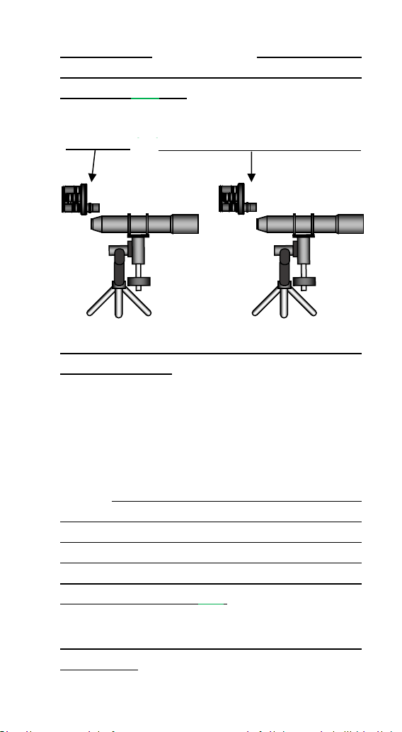
110
motor focuser system and also how to calculate
your focuser range to be typed in “MAX
POSITION” (37) box.
Place your telescope horizontally, as seen on the
previous drawing, and using the [IN] & [OUT]
focusing keys or the Auto Advance Keys (21)
founded in the ROTARION REMOTE CONTROL
software, find your focuser travel steps for both
IN and OUT ranges.
That is, the range outward or “IN-to-OUT” and
the range inward or “OUT-to-IN”. If the
difference among IN-to-OUT and OUT-to-IN
ranges or focus travel numbers are less than 5%,
then OK. Type the larger number of steps in the
“MAX POSITION” box (37).
Place your telescope vertical aiming the Zenit, as
seen below, loaded with your ROTARION and
Range IN = 0 Range max OUT = “Max
POSITION” (37)
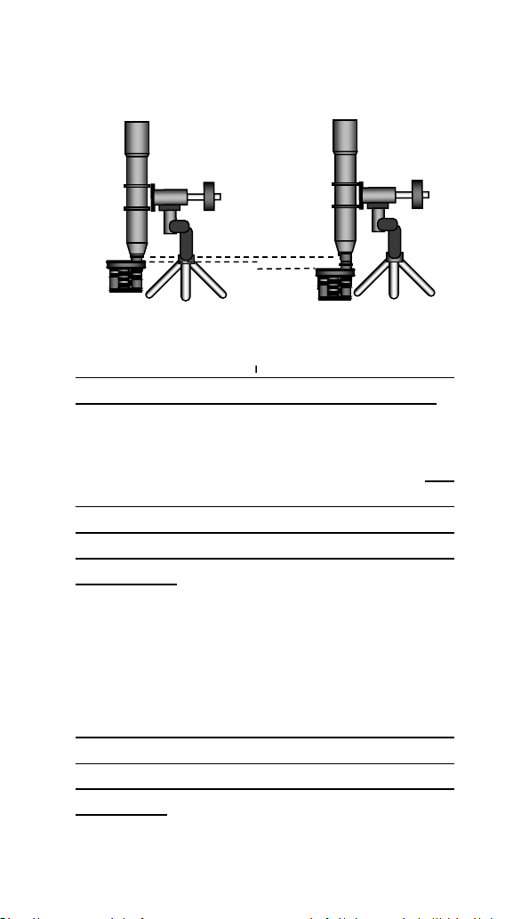
111
any other needed accessories and repeat the
test “IN-to-OUT” and “OUT-to-IN”.
If there is over 5% difference among your “IN-to-
OUT” and/or your “OUT-to-IN” vertical ranges in
number of steps to the number you calculated
on the previous focuser horizontal test and
typed in the “MAX POSITION” box
(37), you
either have mechanical focuser problems or
your motor does not have the necessary
precision or power to achieve focusing
repeatability. Fix it or replace the non-
performing focuser parts before proceeding
with the “TRAINING PROCEDURE”.
3.4. OTHER FOCUSERS:
For some reflecting telescopes without Crayford
focusers and with focusing by internal primary
mirror displacement such as the Schmidt
Cassegrain, or similar, it is not necessary to
perform the previous procedure, since it is

112
sometimes difficult to measure those
telescope’s focus range.
Instead, and before doing the “TRAINING
PROCEDURE”, you must focus manually the
PORT-1 eyepiece and fine-tune the focus to a
NEAR object using the IN or OUT keys or with the
Auto Advance Keys (21) and select the “30,000”
option in the drop-down menu (42) and after do
a “RESET POSITION” (43) found in the
SETUP>CONFIG screen.
The result should be a “30,000” displayed at the
“CURRENT POSITION” counter (25) and a NEAR
object focused with eyepiece in position PORT-1
of the ROTARION. If so, proceed to the TRAINING
PROCEDURE.
If you do not follow the previous
recommendation, you may reach “0” in the
“CURRENT POSITION” counter (25) when
focusing later with higher power and small mm
number eyepiece while teaching the ROTARION
AUTOFOCUS for the FAR and VERY FAR offsets.
If so, you will be unable to complete the
TRAINING PROCEDURE correctly, you will have
to repeat the TRAINING PROCEDURE again from
a largest focus coordinate in eyepiece PORT-1,
selecting and focusing a NEAR object again, and

113
resetting “CURRENT POSITION” counter
(25) to
30,000, as explained previously in this section.
3.5. OTHER FOCUSERS, IMAGING SCT:
Follow the steps of previous section 3.4. when
using imaging optics in Schmitt-Cassegrain
telescopes.
The recommended optics for C6 - C8 – C9,25 –
C11 – C14 telescopes are found in
AstronSCIENTIFIC website, menu TECH INFO.
In this case, focus first with the recommended
reducer/flattener 0.63x in PORT-1 before doing
the “Training Procedure” using the IN or OUT
keys or with the Auto Advance Keys (21) and
select the “30,000” option in the drop-down
menu (42) and after do a “RESET POSITION” (43)
found in the SETUP>CONFIG screen.
Place your SCT horizontally during daytime to
perform the “Training Procedure”
After doing the “Training procedure” calculate
your backlash (in C8 with Feather-Touch motor
should be around 400).
Only after successfully complete the “Training
Procedure” and typing the correct backlash and
successfully focusing automatically with the
Rotarion AutoFocus, activate the SCT Mirror -
Lock option box.

114
4. TRAINING PROCEDURE
TERRESTRIAL USE
If you are going to use your ROTARION for
terrestrial observation such as birding or
digiscoping, place your telescope horizontally
and define your viewing area as in NEAR, FAR,
and VERY FAR. Choose 3 non-moving objects
NEAR, FAR and VERY FAR as focusing reference.
The smaller the range of view or viewing
distance among NEAR, FAR & VERY FAR, the
better autofocus results you will get for objects
located within that viewing area.
Example: it is better to define a viewing area
from NEAR to VERY FAR of 0,5 to 3 miles (or Km)
than a viewing area of twice or double the range
such as from 0,5 to 6 miles (or Km). The smaller
the viewing area, the more precise automatic
focusing results you will achieve within that
range.
ASTRONOMICAL USE
If you are going to use your ROTARION for
nighttime astronomical observation or astro-
imaging, place your telescope inclined to your
most common position (for example, around
60, 70 or 80 degrees over the horizon) and
define your viewing area as in NEAR=Moon,
FAR=Planets and VERY FAR=Stars.
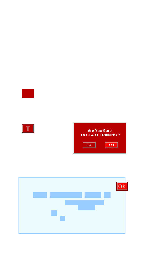
115
TRAINING
With your telescope select 3 objects at different
distances:
3a First object NEAR / (Near-Moon)
3b Second object FAR / (Far-Planet)
3c Third object VERY FAR / (Very Far-Star)
Before starting the TRAINING Procedure,
you will need to select the eyepiece from
PORT-1.
Press the
[TRAINING]
button (you must
have the eyepiece in
position 1).
Accept the question of whether you are sure to
start TRAINING.
In the ROTARION HAND CONTROL choose
the option
MENU 5. Focus Config Training ON
Accept the question Are You Sure? Yes
In the bottom line appears TN: 0
The flashing T key remind us that we are in
Training and the N indicates the NEAR object
chosen in point 3a.
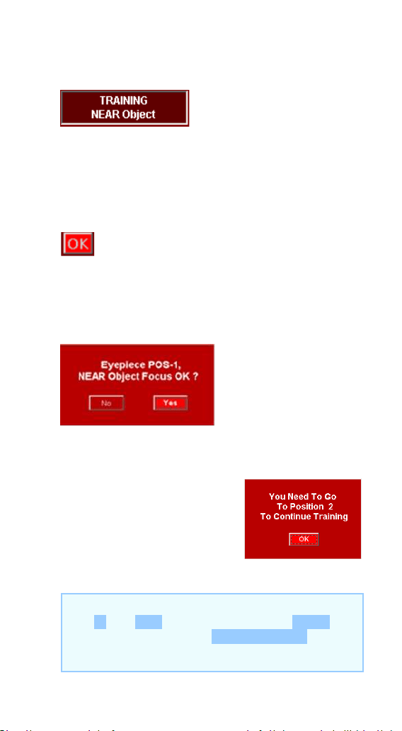
116
4.1. NEAR OBJECT
Using the eyepiece in
position 1 (PORT-1) and
using the [IN] / [OUT] keys, focus on the closest
object chosen in point 3a.
With a good fine focus, press the [OK] key that
appears next to the TRAINING key.
A window appears with the confirmation that
you have well-focused the NEAR object of
eyepiece 1 in PORT-1.
Click [YES].
A window appears that
reminds us that you must
change to the eyepiece-2 in
PORT-2. Click [OK].
In the ROTARION HAND CONTROL focus with
the IN and OUT keys and briefly press MENU
and accept the question EP1, NEAR OK?
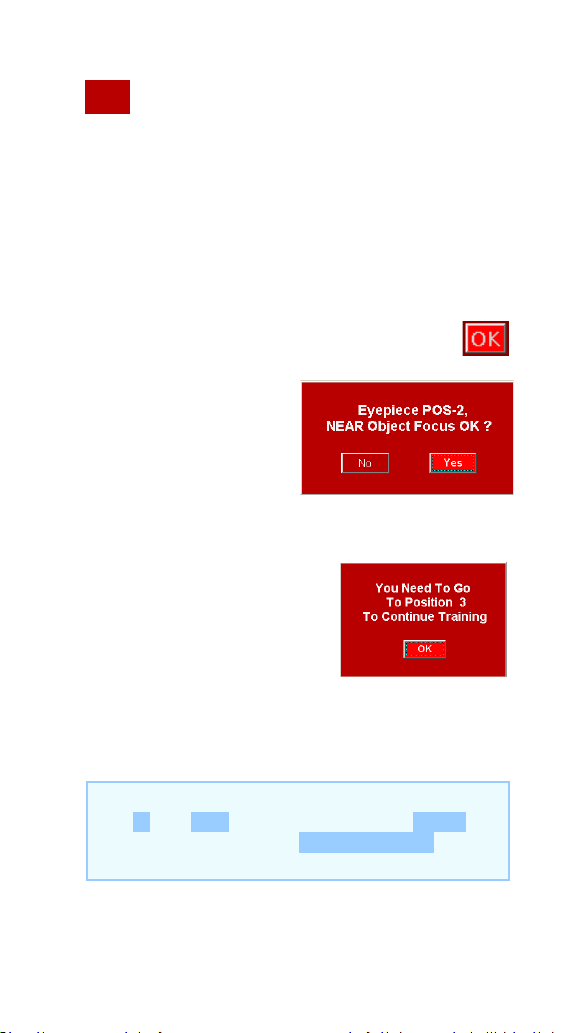
117
Change from eyepiece-1 to eyepiece-2 in
PORT-2 using (16) keys
Using the eyepiece in PORT-2 and using the [IN]
/ [OUT] focusing keys, focus the same object
chosen in point 3a.
With a good fine focus, press the [OK] key.
Confirm that you have
well focused the
NEAR object of the
eyepiece 2 in PORT-2.
Click [YES].
A window appears that
reminds us that you must
change to the next
eyepiece-3 in PORT-3.
Click [OK].
In the ROTARION HAND CONTROL focus with
the IN and OUT keys and briefly press MENU
and accept the question EP2, NEAR OK?
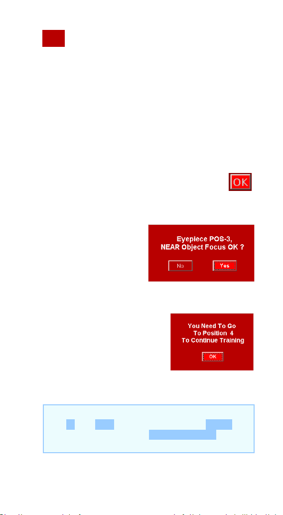
118
Change from eyepiece-2 located in PORT-
2 to eyepiece-3 in PORT-3 using the
(16)
keys.
Using the eyepiece in PORT-3 and using the [IN]
/ [OUT] keys, focus the same object chosen in
point 3a.
With a good fine focus, press the [OK] key.
Confirm that you
have well focused the
NEAR object of the
eyepiece 3. Click
[YES].
A window appears that
reminds us that you must
change to the eyepiece-4
in PORT-4. Click [OK].
In the ROTARION HAND CONTROL focus with
the IN and OUT keys and briefly press MENU
and accept the question EP3, NEAR OK?
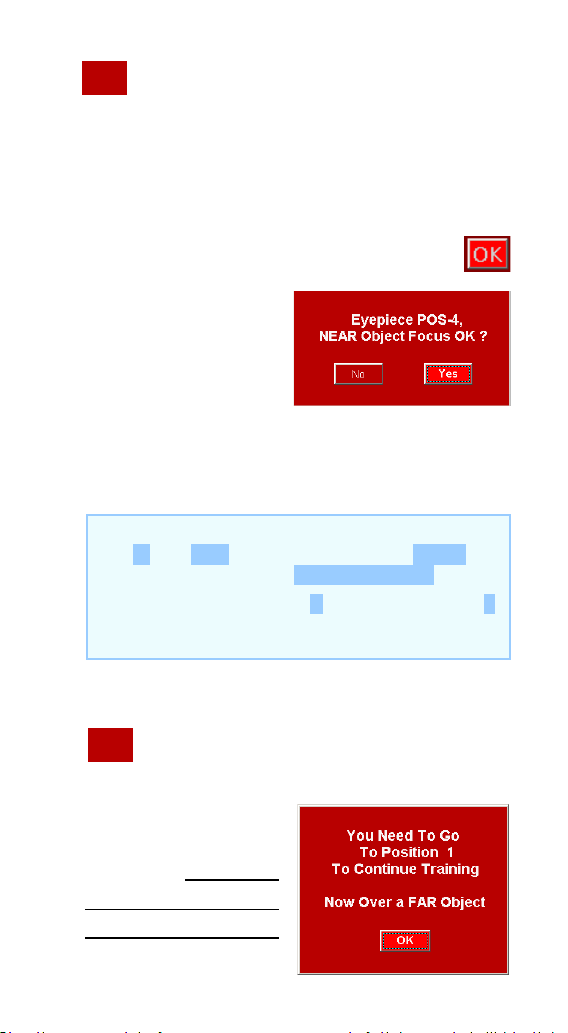
119
Change from eyepiece-3 to eyepiece-4 in
PORT-4 using the
(16) keys.
Using the eyepiece in PORT-4 and using the [IN]
/ [OUT] keys, focus the same object chosen in
point 3a.
With a good fine focus, press the [OK] key.
Confirm that you
have well focused
the NEAR object of
the eyepiece 4. Click
[YES].
“We already know the focus coordinates for
NEAR objects”
Now you must select yepiece-1 in PORT-
1.
This window reminds
us, and indicates that
you must select the
FAR object (distant)
chosen in point 3b
In the ROTARION HAND CONTROL focus with
the IN and OUT keys and briefly press MENU
and accept the question EP4, NEAR OK?
In the bottom line the N letter change to F
indicating the FAR object chosen in point 3b.
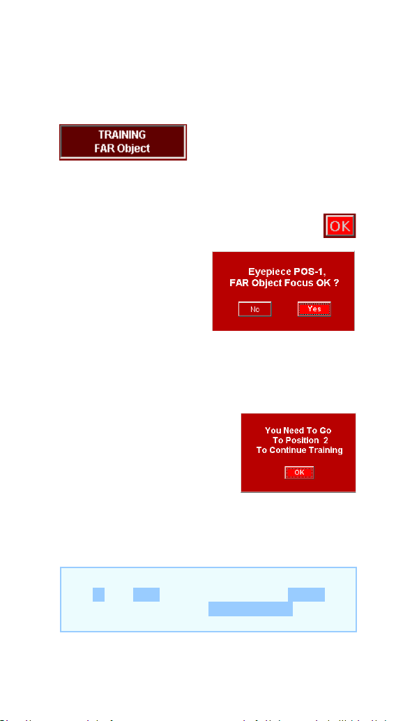
120
with the eyepiece 1 in PORT-1. Click [OK].
4.2. FAR OBJECT
Using the eyepiece in
position 1 and using the
[IN] / [OUT] keys, focus the far object chosen in
3b.
With a good fine focus, press the [OK] key.
A window appears
with the confirmation
that you have well-
focused the FAR object (distant) of the eyepiece
1 in PORT-1. Click [YES].
A window appears that
reminds us that you must
change to the eyepiece-2 in
PORT-2. Click [OK].
In the ROTARION HAND CONTROL focus with
the IN and OUT keys and briefly press MENU
and accept the question EP1, FAR OK?
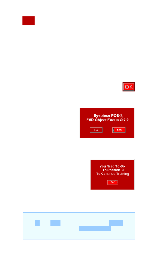
121
Change from eyepiece-1 to eyepiece-2
using the
(16) keys.
Using the eyepiece in PORT-2 and using the [IN]
/ [OUT] keys, focus the same object chosen in
point 3b.
With a good fine focus, press the [OK] key.
Confirm that you have
well focused the FAR
object on the
eyepiece 2. Click
[YES].
A window appears that
reminds us that you must
change to the eyepiece 3 in
PORT-3. Click [OK].
In the ROTARION HAND CONTROL focus with
the IN and OUT keys and briefly press MENU
and accept the question EP2, FAR OK?
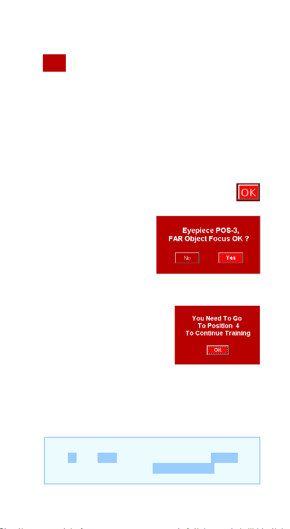
122
Change from eyepieces from PORT-2 to
PORT-3 using the
(16) keys.
Using the eyepiece in position 3 and using the
[IN] / [OUT] keys, focus the same object chosen
in point 3b.
With a good fine focus, press the [OK] key.
Confirm that you have
well focused the FAR
object of the eyepiece
3. Click [YES].
A window appears that
reminds us that you must
change to the eyepiece 4 in
PORT-4. Click [OK].
In the ROTARION HAND CONTROL focus with
the IN and OUT keys and briefly press MENU
and accept the question EP3, FAR OK?
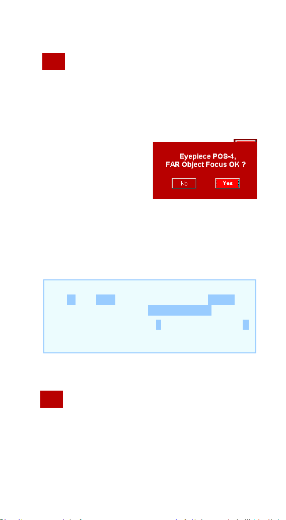
123
Change from eyepiece in PORT-3 to the
eyepiece in PORT-4 using the
(16) keys.
Using the eyepiece in PORT-4 and using the [IN]
/ [OUT] keys, focus the same object chosen in
point 3b.
With a good fine
focus, press the [OK]
key.
Confirm that you have
well focused the FAR object of the eyepiece 4.
Click [YES].
“We already know the focus coordinates for
FAR objects”
Now you must change to eyepiece-1 in
PORT-1.
In the ROTARION HAND CONTROL focus with
the IN and OUT keys and briefly press MENU
and accept the question EP4, FAR OK?
In the bottom line the F letter change to V
indicating the VERY FAR object chosen in point
3c.
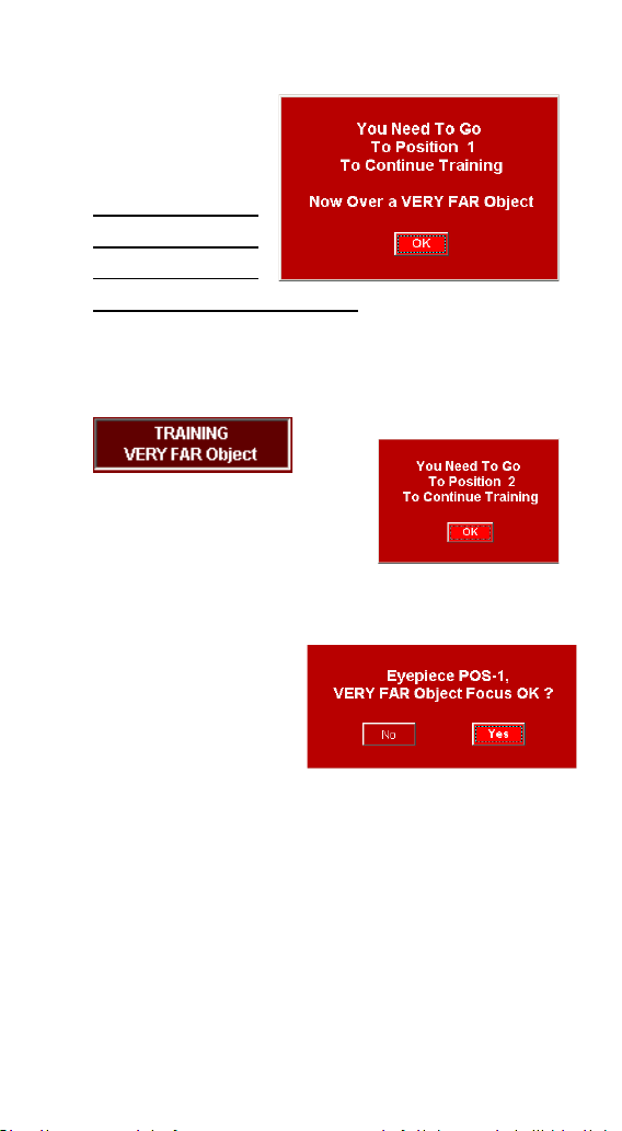
124
This window
reminds us, and
indicates that
you must select
the VERY FAR
object (very
distant) chosen in point 3c. Click [OK].
4.3. VERY FAR Object
Using the eyepiece in
position 1 and using the
[IN] / [OUT] keys, focus the
VERY FAR object chosen in 3c.
With a good fine
focus, press the
[OK] key.
Confirm that you have well focused the VERY
FAR object of eyepiece-1. Click [YES].
A window appears that reminds us that you
must change to the eyepiece 2 in PORT-2. Click
[OK].
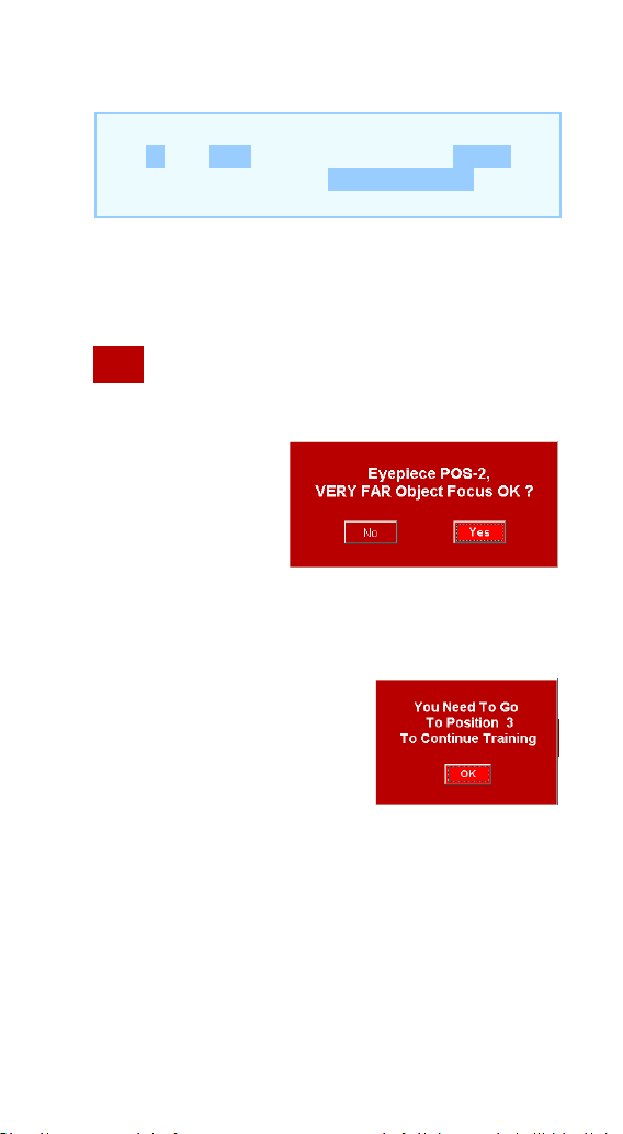
125
Change from eyepiece-1 to eyepiece-2 in
PORT-2 using the (16) keys.
Using the
eyepiece in
position 2 and
using the [IN] /
[OUT] keys, focus the same object chosen in
point 3c.
With a good fine focus,
press the [OK] key.
Confirm that you have well focused the VERY
FAR object of the eyepiece 2. Click [YES].
A window appears that reminds us that you
must change to the eyepiece 3 in PORT-3. Click
[OK].
In the ROTARION HAND CONTROL focus with
the IN and OUT keys and briefly press MENU
and accept the question EP1, VFAR OK?
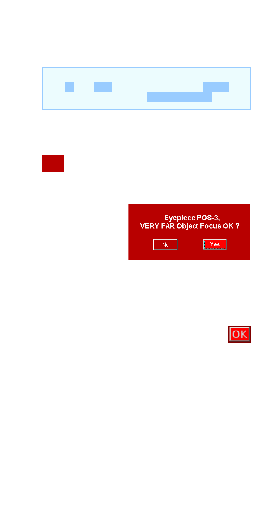
126
Change from eyepiece-2 to eyepiece-3 in
PORT-3 using the
(16) keys.
Using the
eyepiece in
position 3 and
using the [IN] /
[OUT] keys, focus the same object chosen in
point 3c.
With a good fine focus, press the [OK] key.
Confirm that you have well focused the FAR
object of the eyepiece 3. Click [YES].
In the ROTARION HAND CONTROL focus with
the IN and OUT keys and briefly press MENU
and accept the question EP2, VFAR OK?

127
A window appears that reminds us that you
must change to the eyepiece 4 in PORT-4. Click
[OK].
Change
from
eyepiece-3 to
eyepiece-4 in PORT-4 using the
(16) keys.
Using the eyepiece in position 3 and using the
[IN] / [OUT] keys, focus the same object chosen
in point 3c.
With a good fine focus, press the [OK] key.
Confirm that you have well
focused the VERY FAR
object of the eyepiece 4.
Click [YES].
“We already know the focus coordinates for
VERY FAR objects”
In the ROTARION HAND CONTROL focus with
the IN and OUT keys and briefly press MENU
and accept the question EP3, VFAR OK?

128
TRAINING Procedure is over!
You have successfully completed the TRAINING
PROCEDURE, click [OK] to go to your ROTARION
REMOTE CONTROL software MAIN SCREEN.
4.4. TRAINING completed
During the TRAINING procedure, you have
entered in the memory of the ROTARION
AUTOFOCUS the focus coordinates for objects
NEAR, FAR and VERY far for each of the
eyepieces in PORT-1 till PORT-4.
You can access these coordinates (30) of the
[FOCUS OFFSETS] panel using the drop-down
list
(28).
In the ROTARION HAND CONTROL focus with
the IN and OUT keys and briefly press MENU In
the ROTARION HAND CONTROL focus with the
IN and OUT keys and briefly press MENU and
accept the question EP4, VFAR OK?
Appears TRAINING Is DONE. Training is over.

129
In the ROTARION HAND CONTROL we can
access them through the option:
MENU 5. Focus Config Travel
NEAR/FAST/VFAST
Note: We can change these values if
necessary or by experimentation. We
recommend not to change the focus
coordinates obtained by the TRAINING.

130
H-Ready for Observation
1. Observing an Object
Once the TRAINING is done you have the
equipment ready for observation either for
daytime terrestrial use or nighttime astronomy
use, using only the ROTARION REMOTE
CONTROL main screen with the ROTARION
AUTOFOCUS mini panel activated
(31).
When you select an object for observation, you
first observe it with the eyepiece of smaller
magnification and with the largest mm number,
Eyepiece 1, situated at position PORT-1. Decide
if the observed object is NEAR, FAR or VERYFAR
(28) and use the number of steps indicated in
the panel using the drop-down list
so it equals
the number in the counter “CURRENT
POSITION” (25) as the initial focusing
coordinate. Then you continue to fine-tune the
focus to sharpen the image using always the [IN]
or [OUT] keys or with the Auto Advance Keys
(21).
Once the object in PORT-1, is in focus and
centered, you are ready to change to eyepiece
in position PORT-2

131
When you change to position PORT-2 (where
you have a more powerful eyepiece, Eyepiece 2)
the program calculates the focus coordinate for
this eyepiece using mathematical algorithms.
These algorithms use the values set during the
TRAINING procedure. This way, the object will
appear automatically focused or nearly focused.
If necessary, fine-tune the focus of PORT-2 lens
using the [IN] or [OUT] keys or with the Auto
Advance Keys (21). If the ROTARION
AUTOFOCUS algorithm focus proposal for the
second eyepiece in PORT-2 needs user’s fine
focus improvement, may be due to changing
atmospheric conditions, the ROTARION
AUTOFOCUS will memorize the new user’s focus
offset among PORT-1 and PORT-2 optics.
Similarly, when selecting position PORT-3
(where you have a higher-powered eyepiece,
Eyepiece 3) the software calculates the focus
coordinate for this third eyepiece using the
value you have set for the Eyepiece 2 in PORT-2
and the focus values memorized during
TRAINING.
The object will appear in the Eyepiece 3 visual
field automatically focused or nearly focused. If
necessary, again, fine-tune the focus. If you
must fine focus the third eyepiece in PORT-3,
the ROTARION AUTOFOCUS will memorize the
new focus adjustment among PORT-2 and
PORT-3.

132
Follow the previous procedure for your fourth
position PORT-4 eyepiece or ROTARION
PRIMEFOCUS kit (if installed).
After the fine focus of PORT-1 till PORT-4, you
can return to a previous (lower power) eyepiece
and the viewed object will be automatically
focused, with the latest memorized fine focus
offset.
In other words, once you have fine-tuned the
focus from PORT-1 till PORT-4, you can change
back and forth to any chosen eyepiece and your
ROTARION AUTOFOCUS will produce precise
and well-focused results.
Moreover, the ROTARION AUTOFOCUS system
allows the user to modify slightly the fine-focus
offset without erasing the previous memorized
fine-focus coordinate. If the user’s focus
modification is large, the algorithm will propose
a new focus coordinate for the following more
powerful eyepieces.
As indicated previously, for this focusing
process to work accurately, it is necessary to
work with good quality mechanical focusers &
motor focus systems. Although the ROTARION
AUTOFOCUS can operate with DC motors, the
best results are obtained with stepper motors
and rack and pinion focusers.

133
2. Changing to a New Object
If you change the observed object for another
object at a different distance, you must go to
PORT-1 and focus again using the [IN] or [OUT]
keys or with the Auto Advance Keys (21), so the
system knows that you are observing a new
object with new focus offsets and coordinates.
After, you will have to go to PORT-2 and focus
again if necessary. The ROTARION AUTOFOCUS
will erase the previous memorized fine-focus
offsets from the previously viewed object and
will calculate new ones for the new viewed
object.
As you change from eyepiece in PORT-1 to the
PORT-2 and so on, you may have to fine-focus
and center the currently viewed object before
changing to the next eyepiece so the ROTARION
AUTOFOCUS memorizes the new fine-focus
offsets and focus coordinates among PORT-1 till
PORT-4.
3. Resetting the Focuser
If you accidentally or manually move the focuser
without using the IN or OUT keys or without the
Auto Advance Keys (21), the ROTARION
AUTOFOCUS coordinate will not match the
mechanical focus coordinates of your focuser

134
and the ROTARION AUTOFOCUS will not work
properly.
Therefore, you must synchronize again your
focuser position with the ROTARION
AUTOFOCUS coordinate displayed in the
CURRENT POSITION counter
(25).
Go to PORT-1, select an object you chose during
TRAINING and focus it, or move your focuser to
max inward coordinate (0) and press the key
RESET POSITION
(43) found in the
SETUP>CONFIG screen.
See in this manual Chapter E- Config Screen,
section Selector ResetPos (42) and section
Reset Position
(43) and follow the procedure.

135
I-Additional Product
Information
Please read the following instructions and
information.
1. Product Compliance Information
The AstronSCIENTIFIC S.L. corporation with
address at Marti i Julia 6-8, Barcelona 08834
Spain E.U. has certified this product with the IEC
61010-1 Norm for Safety requirements for
electrical equipment for measurement, control,
and laboratory use in compliance with the
Bureau Veritas Consumer Products Services
Germany GmbH corporation based at Türkheim,
Germany.
If the equipment is used in a manner not
specified by the manufacturer, the protection
provided by the equipment may be impaired.
• The CE Certificate Product Marking:
136
• Instruction Manual Version:
Rotarion AutoFocus V:1.0 CE
2. Service, Maintenance, Cleaning,
Disposal, Serial Number, and
Dealer:
Car adapter fuse:
• 4 Amp 12V 6.3x32mm, fast acting.
• To replace it, unscrew the tip and replace.
Operating environmental conditions:
• Max. 2000m. / 0-40
o
C / 32-104 Fahrenheit and
80% humidity.
Degree of Protection IEC 60529:
• Not applicable.
The Power Supply:
• Input: 100-240Vac; 50/60Hz; 0,55A
137
Output: 12Vdc; 2A; Limited Power Source
• Disconnect the Power Supply unit from the
ROTARION. The Power Supply unit must be
freely accessible and must not be covered nor
obstructed for disconnecting the ROTARION
when needed.
• Only use the supplied Power Supply unit.
• Please compare the rating plate of the Power
supply unit with the local mains voltage and
frequency.
Maintenance technical data:
• Maintenance free.
Cleaning:
• Use a soft cloth without liquids.
Disposal:
•
• Equipment with this symbol shall not be
disposed of together with household or
commercial waste.
• Please find out about separate disposal at your
regional offices.
• The directive 2012/19/EU on waste electrical
and electronical equipment (WEEE) is applicable
in the European Union member states.
Serial Number (or PN): ____________________
Dealer: ________________________________
Date: _________________________________

138
J-Warranty
The warranty is extended to all countries where
this product is distributed by AstronSCIENTIFIC
S.L. or by a distributor assigned by it. This
warranty is subject to the legal provisions of
each country.
6. Warranty period
The Warranty period is 2 years from the date of
the sales invoice issued by AstronSCIENTIFIC S.L.
Or by the distributor authorized by
AstronSCIENTIFIC S.L.
7. Warranty Coverage
The conformity of the product is warranted
according to the use for which it is intended.
Within the warranty period, we will remedy any
defect in the operation of the product due to its
manufacture, whether repairing, replacing parts
or providing a new product, provided that the
option chosen is feasible and not economically
disproportionate according to the criteria of
AstronSCIENTIFIC S.L.
For any of the three options, repair,
replacement of parts or exchange for a new
product, the consumer must go to the
authorized distributor of AstronSCIENTIFIC S.L.
where the product was purchased.

139
8. Warranty Nullity
This warranty will not be valid in the following
cases:
Misuse, improper use, neglect, accident, or
deterioration of the product due to failure to
comply with the warnings and restrictions
contained in this Instruction Manual or in the
operating instructions provided by
AstronSCIENTIFIC S.L.
External agents such as water or other harmful
chemicals, obstructive or corrosive.
Likewise, faults or malfunctions caused by
incorrect voltages and electrical installations
will not be covered by this guarantee.
This warranty does not cover any product that
has been altered or repaired by any person
other than AstronSCIENTIFIC S.L. repair
personnel, or any product whose serial number,
model number or identification has been
removed, is defective or altered.
AstronSCIENTIFIC S.L. Shall not be liable for any
indirect, special, incidental, or consequential
damages related to the sale or use of the
product.

140