Owner's Manual/Manual Del Propietario
@
314 HP
31_SMN=GARAGE DOOR OPENER
ABRIDOR DE PUERTA DE COCHERA
For Residential Use Only/S61o para uso residencial
DE 315_H_
Model/Modelo 139.53925DS
m
Z
I=-
I
O'J
m
O_
"13
Z_
O
r-'
Read and follow all safety rules and
operating instructions before first use
of this product.
Fasten the manual near the garage
door after installation.
Periodic checks of the opener are
required to ensure safe operation.
Leer y seguir todas las reglas de
seguridad y las instrucciones de
operaci6n antes de usar este producto
por primera vez.
Guardar este manual cerca de la
puerta de la cochera.
Se deben realizar revisiones peri6dicas
del abridor de puertas para asegurar
su operaci6n segura.
Sears, Roebuck and Co., Hoffman Estates, IL 60179 U.S.A
wwwsears, comicraftsman
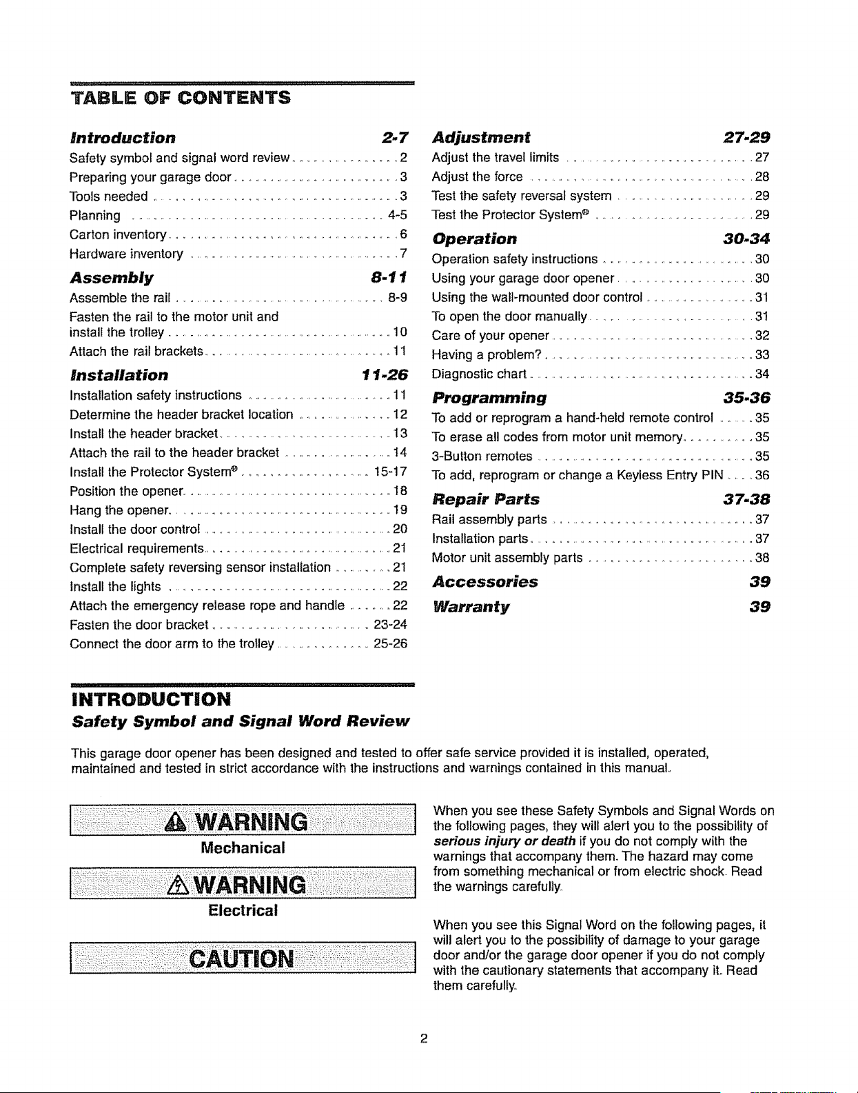
TABLE OF CONTENTS
Introduction 2- 7
Safety symbol and signal word review ........................ 2
Preparing your garage door ............................................. 3
Tools needed .......................................................... 3
Planning ................................................................. 4-5
Carton inventory
......................................................
6
Hardware inventory ....................................................... 7
Assembly 8-11
Assemble the rail ....................................................... 8-9
Fasten the rail to the motor unit and
install the trolley ........................................................ 10
Attach the rail brackets .............................................. 11
Installation 11-26
Installation safety instructions .................................... 11
Determine the header bracket location ....................... 12
Install the header bracket .......................................... 13
Attach the rail to the header bracket ........................... 14
install the Protector Systeme .......................... 15-17
Position the opener.
......................................................
18
Hang the opener ..................................................... 19
Install the door control ............................................... 20
Electrical requirements ............................................. 21
Complete safety reversing sensor installation ........... 21
Install the lights ....................................................... 22
Attach the emergency release rope and handle .......... 22
Fasten the door bracket .......................................... 23-24
Connect the door arm to the trolley ................... 25-26
Adjustment 27.29
Adjust
the
t
r_v_l
I_m_ts
.............................................
27
Adjust the force ................................................ 28
Test the safety reversal system .................................. 29
Test the Protector System ® ......................................... 29
Operation 30.34
Operation safety instructions.................................. 30
Using your garage door opener .............................. 30
Using the wall-mounted door control ............................. 31
To open the door manually ...................................... 31
Care of your opener ................................................ 32
Having a problem? .................................................... 33
Diagnostic chart ................................................... 34
Programming 35-36
To add or reprogram a hand-held remote control ......... 35
To erase all codes from motor unit memory'.............. 35
3-Button remotes ........................................................... 35
To add, reprogram or change a Keyless Entry PIN ...... 36
Repair Parts 37-38
Rail assembly parts ........................................ 37
Installation parts .............................................................. 37
Motor unit assembly parts .................................... 38
Accessories 39
Warranty 39
INTRODUCTION
Safety Symbol and Signal Word Review
This garage door opener has been designed and tested to offer safe service provided it is installed, operated,
maintained and tested in strict accordance with the instructions and warnings contained in this manual..
Mechanical
Electrical
When you see these Safety Symbols and Signal Words on
the following pages, they will alert you to the possibility of
serious injury or death if you do not comply with the
warnings that accompany them_The hazard may come
from something mechanical or from electric shock Read
the warnings carefuliy
When you see this Signal Word on the following pages, it
will alert you to the possibility of damage to your garage
door and/or the garage door opener if you do not comply
with the cautionary statements that accompany it..Read
them carefully.
2
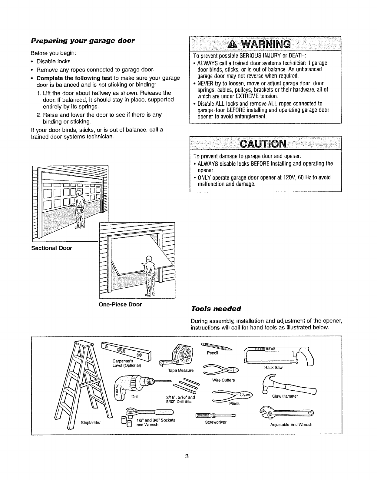
Preparing your garage door
Before you begin:
° Disable locks
- Remove any ropes connected to garage door.
- Complete the following test to make sure your garage
door is balanced and is not sticking or binding:
1 Lift the door about halfway as shown Release the
door If balanced, it should stay in place, supported
entirely by its springs
2_Raise and lower the door to see if there is any
binding or sticking
If your door binds, sticks, or is out of balance, ca!l a
trained door systems technician
To preventpossibleSERIOUSINJURYor DEATH:
- ALWAYScall a traineddoor systems technicianif garage
door binds, sticks, or is out of balance An unbalanced
garagedoor maynot reversewhen required1
• NEVERtry to loosen,move or adjustgaragedoor, door
springs,cables,pulleys, bracketsor their hardware,all of
whichare underEXTREMEtension
• DisableALL locks and removeALL ropes connectedto
garagedoor BEFOREinstallingand operatinggaragedoor
openerto avoid entanglement
To preventdamageto garagedoor and opener:
. ALWAYSdisablelocks BEFOREinstallingand operatingthe
opener
= ONLYoperategaragedoor openerat 120V,60 Hzto avoid
malfunctionand damage
Sectional Door
One-Piece Door
Tools needed
During assembly, installation and adjustment of the opener,
instructions will call for hand tools as illustratedbelow.
Lev_ (Optional)
Tape Measure
Pencil
V_reCutters
Hack Saw
Slepladder
3/16", 5/t 6" and
5/32" Drill Bits
Screwdriver
Claw Hammer
Adiustable End Wrench
Planning
Identify the type and height of your garage door. Survey
your garage area to see if any of the conditions below
apply to your installation Additional materials may be
required You may find it helpful to refer back to this page
and the accompanying illustrations as you proceed with
the installation of your opener
Depending on your requirements, there are several
installation steps which may call for materials or hardware
not included in the carton
o Installation Step 1 - Look at the wal! or ceiling above
the garage door. The header bracket must be securely
fastened to structural supports
o installation Step 4 - Depending upon garage
construction, extension brackets or wood blocks may be
needed to install sensors
° Installation Step 4 - Alternate floor mounting of the
safety reversing sensor will require hardware not
provided
* Installation Step 6 - Do you have a finished ceiling in
your garage? If so, a support bracket and additional
fastening hardware may be required
Do you have an access door in addition to the garage
door? If not, Model 53702 Emergency Key Release is
required See Accessories page
Look at the garage door where it meets the floor Any
gap between the floor and the bottom of the door must
not exceed 1/4" (6 ram). Otherwise, the safety reversal
system may not work properly See Adjustment Step 3
Floor or door should be repaired_
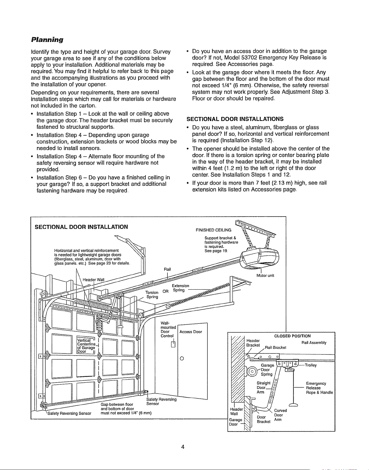
SECTIONAL DOOR INSTALLATIONS
° Do you have a steel, aluminum, fiberglass or glass
panel door? if so, horizontal and vertical reinforcement
is required (Installation Step 12).
• The opener should be installed above the center of the
door. If there is a torsion spring or center bearing plate
in the way of the header bracket, it may be installed
within 4 feet (12 m) to the left or right of the door
center See Installation Steps 1 and 12
• If your door is more than 7 feet (2.13 m) high, see rail
extension kits listed on Accessories page.
SECTIONAL DOOR INSTALLATION
Horizontal and vertical reinforcement
is needed for $_ghtweight garage doo_s
(fiberglass, steel, aluminum, door with
glass panels, etc.) See page 23 for details
Header Wall
Rat!
Torsion OR
Spdng
FINISHED CElUNG
Supped bracket &
faslening hardware
is required.
See page 19
Extension
Spring
Motor unit
Waif
Door
Control
_Sa_ety Reversing Sensor
Safety Reversfng
Gap between floor Sensor
and bottom of door
must not exceed I/4" (6 ram)
AccessDoor
O
CLOSED POSITION
Header
_ackel_RailB_:aGke,
Doo_ I I
O,noio/--
Straighl /_/
°2r4 /
_Curved
_i Ooer ?oor
Brackel Arm
Flail Assembly
:";!". ........
_Trolley
Emergency
Retease
Rope & Handle
Planning (Continued)
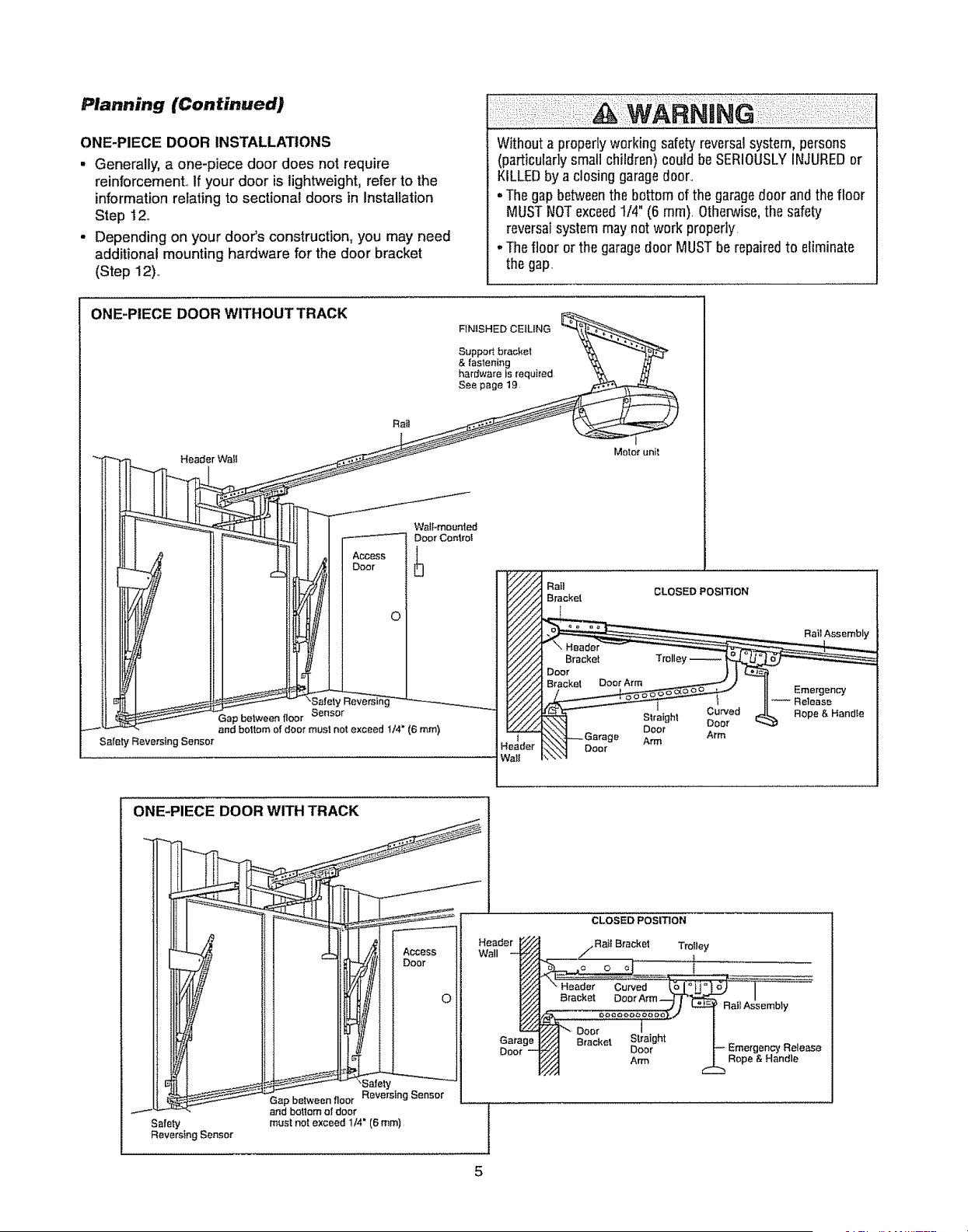
ONE-PIECE DOOR INSTALLATIONS
• Generally, a one-piece door does not require
reinforcement., If your door is lightweight, refer to the
information relating to sectional doors in Installation
Step 12,,
• Depending on your door's construction, you may need
additional mounting hardware for the door bracket
(Step 12).,
Without a properly working safetyreversalsystem, persons
(particularly smallchildren) could be SERIOUSLYINJUREDor
KILLEDby a closing garagedoor,,
. The gapbetweenthe bottom of the garagedoor and the floor
MUSTNOTexceedt/4" (6 ram). Otherwise,the safety
reversalsystem maynot work properly
. The floor or the garagedoor MUSTbe repairedto eliminate
thegap,
ONE-PIECE DOOR WITHOUT TRACK
Safety Reversing Sensor
Rail
jl
jJ
J
Access
Door
i °
Safer
Gap belween floor Sensor
and boltom of door must not exceed 1t4" (6 ram)
WalFmounted
Door Cenlrot
FINISHED CEILING __
Support brackel _ _
& faslening _,_ k_
hardware is required _,_ /_
See page_
Motor unit
eader
ta_l
Rail
Bracket
CLOSED POSITION
ONE-PIECE DOOR WITH TRACK
Safety
ReversingSensor
Gap between floor Reversing Sensor
and bottom of door
must not exceed 1/4" (6 ram)
Garage
Door
CLOSED POSITION
Bracket Trolley
Door
Bracket
Straight
Door
Arm
Assembly
Rope & Handle
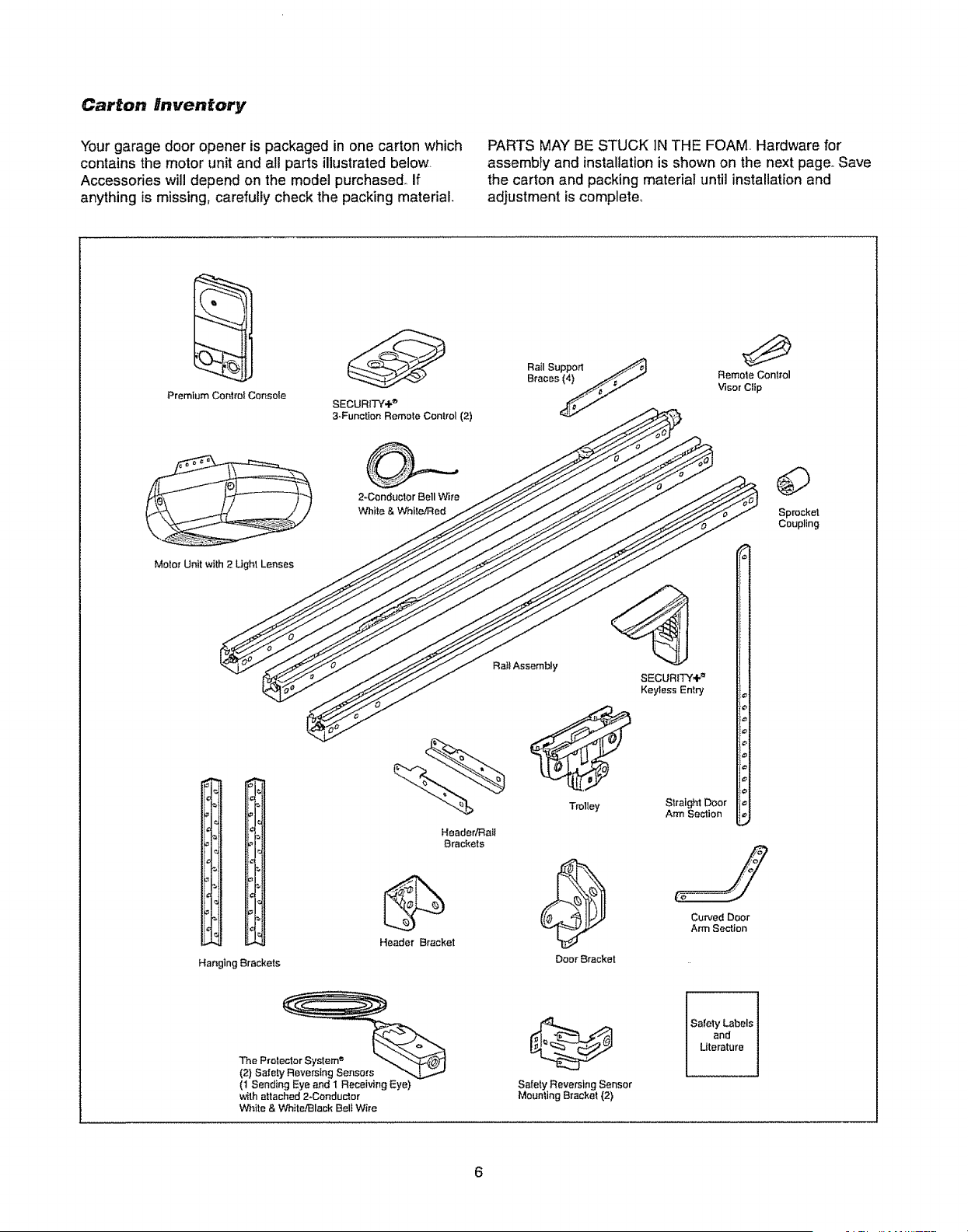
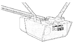
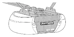
Carton Inventory
Your garage door opener is packaged in one carton which
contains the motor unit and all parts illustrated below
Accessories will depend on the mode] purchased, If
anything is missing, carefully check the packing material,
PARTS MAY BE STUCK iN THE FOAM,, Hardware for
assembly and installation is shown on the next page,,Save
the carton and packing material until installation and
adjustment is complete°
Premium Centre! Console
SECU RIT'-(,{,e'
3-Function Remole Control (2)
RailSupport
Bfaces_
Remote Control
Visor Clip
2*Conductor Bell Wire
V'_ita & While/Red
Sprocket
Coupling
Motor Unit with 2 Ught Lenses
Hanging Brackets
Ra}l Assembly
Header/Rail
Brackets
Header Bracket
Trolley
Door Bracket
SECURITY÷ _'
Keyless Entry
Straight Door
Arm Section
Curved Door
Arm Section
(t Sending ]Eyeand I Receiving Eye)
with attached 2-Conductor
V'_ite & White/Black Belt Wire
Safety Reversing Sensor
Mounting Brackel {2)
Safety Labels
and
Literature
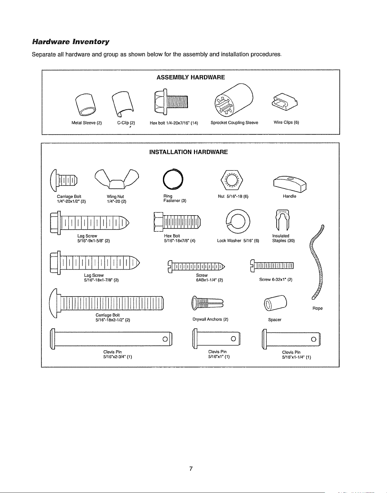
Hardware Inventory
Separate all hardware and group as shown below for the assembly and installation procedures,
Metal Sleeve (2) c-c_p (2)
r
Hex bolt l/4-20x7/16 _(14)
ASSEMBLY HARDWARE
Sprocke_ Coupling Sleeve
Wi_'e Clips (6)
INSTALLATION HARDWARE
Cardage Bolt Wing Nut
114"-20xt12" (2) 1/4'-20 (2)
Lag Screw
5/16"-9xl-5/8" (2)
Lag Screw
5116"-18xl-7/8' (2)
Clevis Pin
Sn6_x2-3,'4"(1)
©
Ring
Fastener (3)
Hex Bol!
5!I 6"-18x718" (4)
Nut 5/16"-t8 (6}
Lock Washer 5/16' (6)
_ l,lilitilitilil,lilil,l,t_
Screw
6ABxl _1I4" (2)
Drywall Anchors (2)
Clevis Pin
5/t6"x1" (1)
Handle
Insulated
Slaples (30)
Screw 6-32x1" (2)
Rope
Spacer
Clevis Pin
S!16'xlq/4' (1)
7
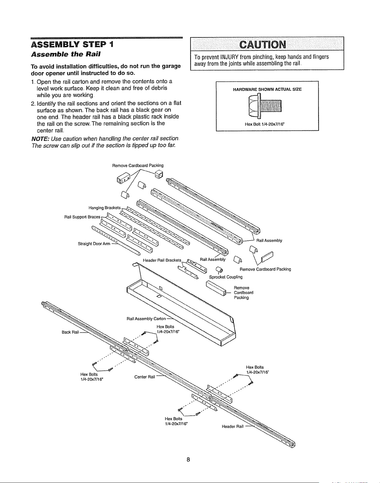
ASSEMBLY STEP 1
Assemble the Rail
To avoid installation difficulties, do not run the garage
door opener until instructed to do so.
1. Open the rail carton and remove the contents onto a
level work surface.. Keep it clean and free of debris
while you are working.
2. Identify the rail sections and orient the sections on a flat
surface as shown.,The back rail has a black gear on
one end. The header rail has a black plastic rack inside
the rail on the screw,,The remaining section is the
center rail..
NOTE: Use caution when handling the center rail section.
The screw can slip out if the section is tipped up too far.
_:__:i:::: _:i :CAUTION::::_I:_:::::::::i:i:
To preventINJURYfrom pinching, keephandsandfingers I
awayfrom the jointswhile assemblingthe rail. I
HARDWARE SHOWN ACTUAL S1ZE
Hex Boll 1/4_20x7tt6"
Remove Cardboard Packing
Hanging Brackets,
Rail Support Braces
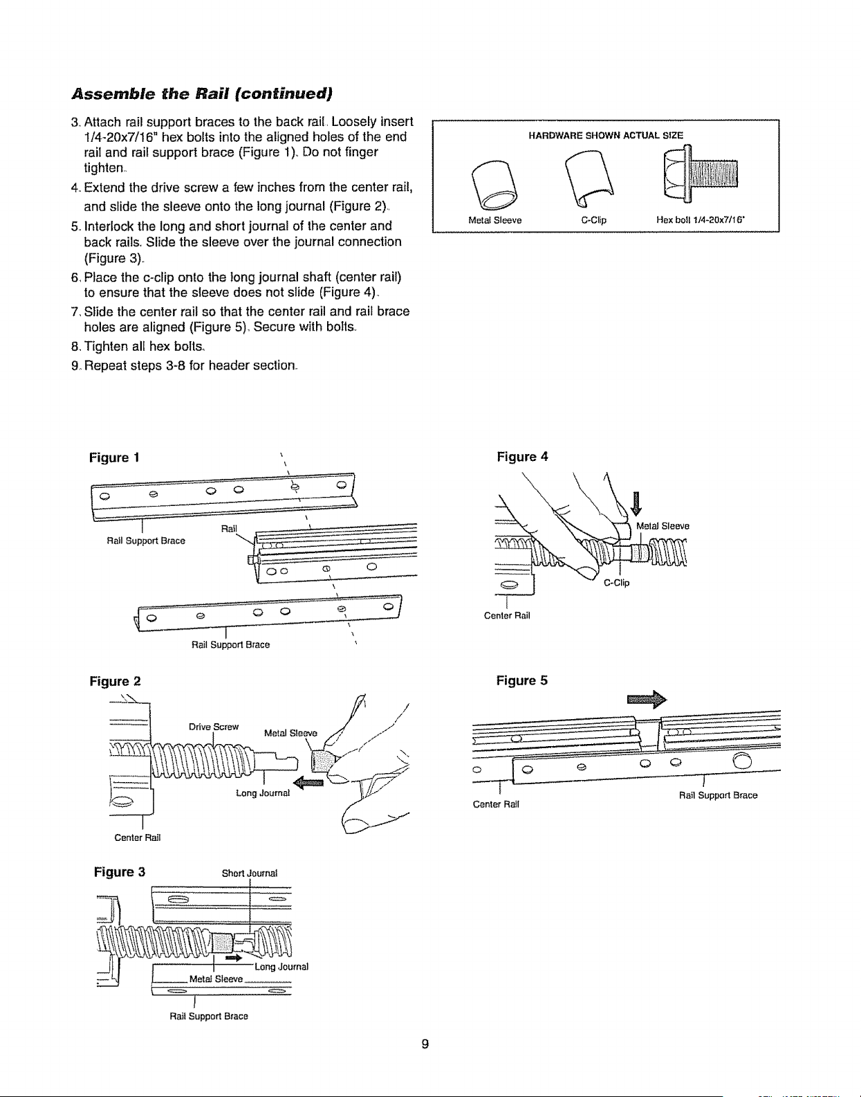
Assemble the Rail (continued)
3, Attach rail support braces to the back rail, Loosely insert
I/4-20x7/16" hex bolts into the aligned holes of the end
rail and rail support brace (Figure 1),,Do not finger
tighten,.
4.,Extend the drive screw a few inches from the center rail,
and slide the sleeve onto the long journal (Figure 2),,
5.,Interlock the long and short journal of the center and
back rails. Slide the sleeve over the journal connection
(Figure 3).,
6, Place the c-clip onto the tong journal shaft (center rail)
to ensure that the sleeve does not slide (Figure 4),,
7, Slide the center rail so that the center rail and rail brace
holes are aligned (Figure 5)_ Secure with bolts,
& Tighten all hex bolts,,
9, Repeat steps 3-8 for header section..
Metal Sleeve
HARDWARE SHOWN ACTUAL SIZE
C-Clip Hex boll 114-20x7116"
Figure 1
Rail Support Brace
Rail Support Brace
Figure 4
'\_ tern Sleeve
Center Rail
Center Rail
, _ //1
Drive Screw Metal Sleeve _/ /
LongJournal i!pi"
Figure 5
Center Rail
Rail Support Brace
Figure 3 Short JournaI
Journal
9
Hex Bolts
1/4-20x7/16'
Motor Ueil
Bracket
Motor Unit
Sprocket
Coupling
\
RaiI Sprocket
qg/
_--- Retease a_m
Foam Packaging
Hex Bolts
1/4-20x71t6"
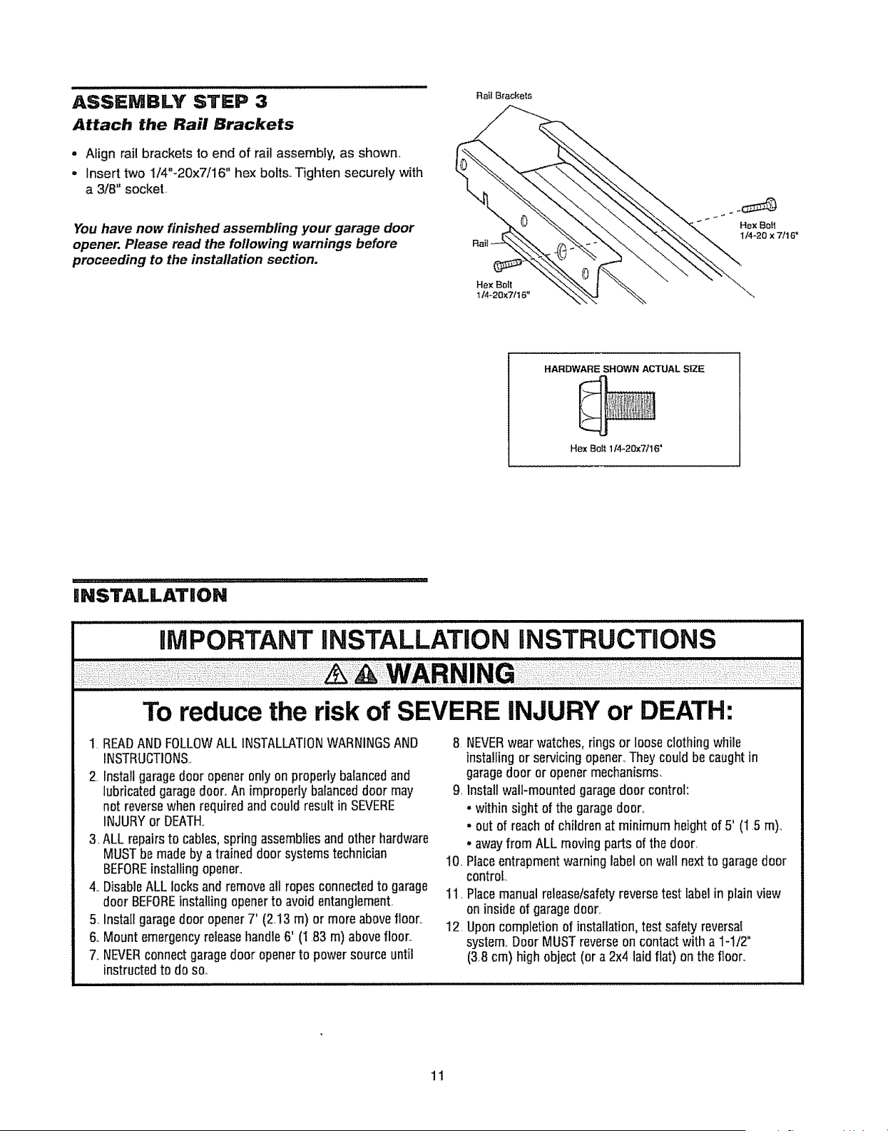
ASSEMBLY STEP 3
Attach the Rail Brackets
• Align rail brackets to end of rail assembly, as shown_
° Insert two 1/4"-20x7/16" hex bolts. Tighten securely with
a 3/8" socket,
You have now finished assembling your garage door
opener. Please read the following warnings before
proceeding to the installation section.
Rail 8rackets
Hex Bolt
114-20x7116"
HARDWARE SHOWN ACTUAL SiZE
Hex Bof_ 114-20x7/16"
iNSTALLATiON
iMPORTANT iNSTALLATiON iNSTRUCTiONS
To reduce the risk of SEVERE INJURY or DEATH:
1, READANDFOLLOWALL INSTALLATIONWARNINGSAND
INSTRUCTIONS.,
2. Install garagedoor opener only on properly balancedand
lubricatedgaragedoor,,Animproperly balanceddoor may
not reversewhen requiredand could resultin SEVERE
INJURYor DEATH.,
3, ALL repairsto cables,spring assembliesand otherhardware
MUSTbe madeby a trained doorsystems technician
BEFOREinstalling opener.,
4.,DisableALLlocks and removeall ropes connectedto garage
door BEFOREinstalling openerto avoid entanglement
5, Install garagedoor opener7' (2.13 m) or more abovefloor,.
6oMount emergencyreleasehandle6' (1 83 m) abovefloor..
7,,NEVERconnectgaragedoor openerto power sourceuntil
instructedto do son
8 NEVERwear watches,rings or loose clothingwhile
installing or servicing opener,.Theycould be caughtin
garagedoor or opener mechan[sms_
9. Install wall-mountedgaragedoor control:
• within sight of the garagedoor_
• out of reachof childrenat minimum height of 5' (1 5 m).,
• awayfrom ALL movingparts of the door,
10. Placeentrapmentwarning label onwall next to garagedoor
control,.
11, Placemanualrelease/safetyreversetest labelin plainview
on insideof garage door,,
12 Uponcompletion of installation,test safetyreversal
system,Door MUSTreverseon contactwith a 1-1/2"
(3.8 cm) high object (or a2x4 laid flat) on the floor.
11
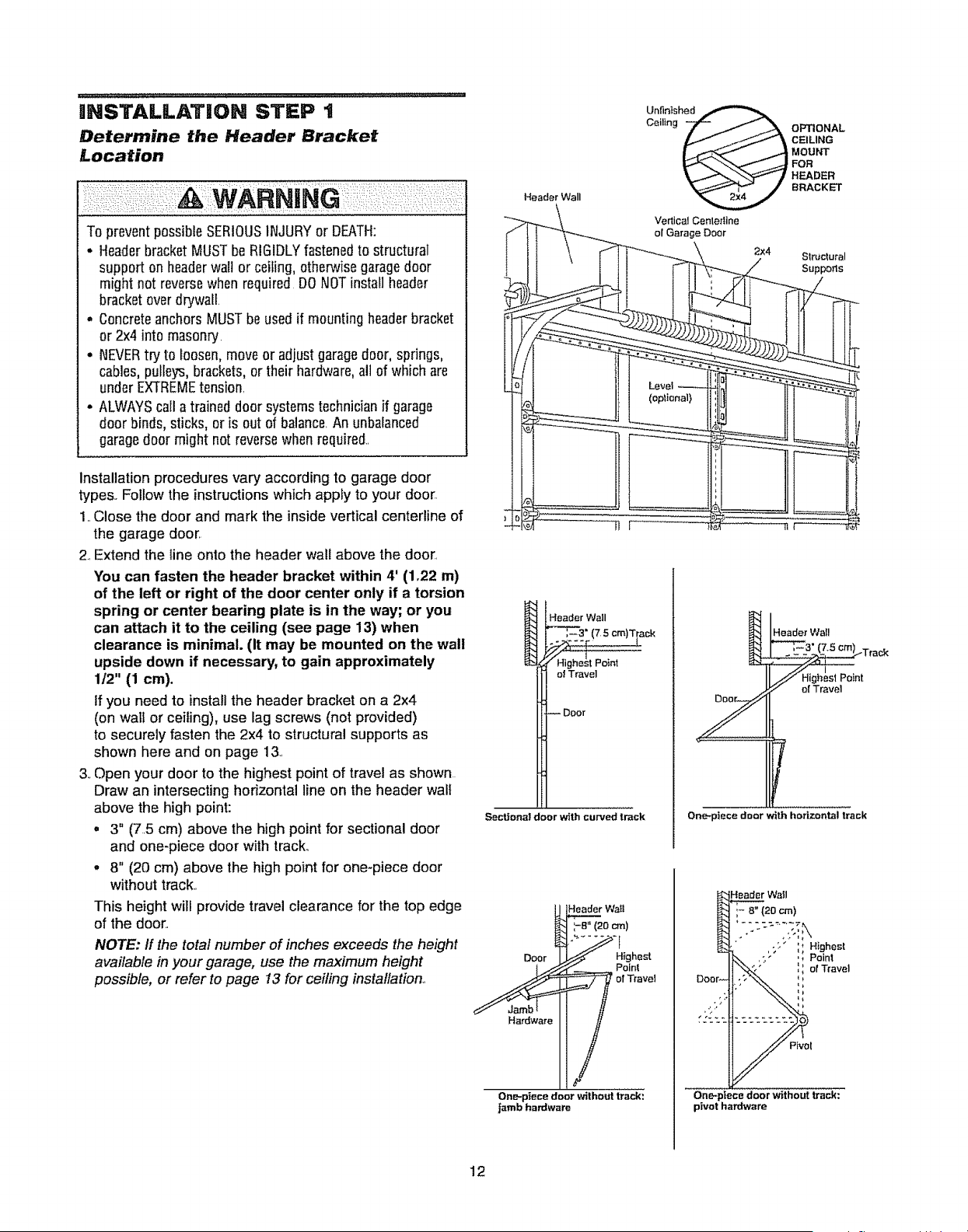
tlNSTALLATiON STEP 1
Determine the Header Bracket
Location
To preventpossibleSERIOUSINJURYor DEATH:
. HeaderbracketMUSTbe RIGIDLYfastenedto structural
supporton headerwall or ceiling, otherwisegaragedoor
might not reversewhen required DONOTinstall header
bracketover drywall
• ConcreteanchorsMUSTbe usedif mountingheaderbracket
or 2x4 into masonry
• NEVERtry to Ioosen,move or adjustgaragedoor, springs,
cables,pulleys,brackets,or their hardware,all of which are
underEXTREMEtension
• ALWAYScall a trained door systemstechnicianif garage
door binds, sticks, or is out of balance An unbalanced
garagedoor might not reversewhen required+
Installation procedures vary according to garage door
types Follow the instructions which apply to your door
1 Close the door and mark the inside vertical centerline of
the garage door
2 Extend the fine onto the header wall above the door
You can fasten the header bracket within 4' (1.22 m)
of the left or right of the door center only if a torsion
spring or center bearing plate is in the way; or you
can attach it to the ceiling (see page 13) when
clearance is minimal. (It may be mounted on the wall
upside down if necessary, to gain approximately
1t2" (1 cm).
ff you need to install the header bracket on a 2x4
(on wall or ceiling), use lag screws (not provided)
to securely fasten the 2x4 to structural supports as
shown here and on page 13
3+Open your door to the highest point of travel as shown
Draw an intersecting horizontal line on the header wall
above the high point:
• 3" (75 cm) above the high point for sectional door
and onepiece door with track°
o 8" (20 cm) above the high point for one-piece door
without track+
This height will provide travel clearance for the top edge
of the door
NOTE: If the total number of inches exceeds the height
available in your garage, use the maximum height
possible, or refer to page 13 for ceiling installation
Header Wall
Vedical Centedine
el Garage Door
(optional)
2x4
Structural
Suppers
Header Wall
'_"_-,--3" (7 5 era)Track
of Travel
-- Door
Sec_ona! door with curved track
Z
Header Wall
Track
_/_ Highest Paint
;" e! Travel
One-piece door with horizontal track
U He_ Wa_l
_ of Travel
One-piece door without track:
jamb hardware
!r Wall
Deal
Pivol
One-piece door without track:
pivot hardware
12
i u i,inullnUlUlu,nu
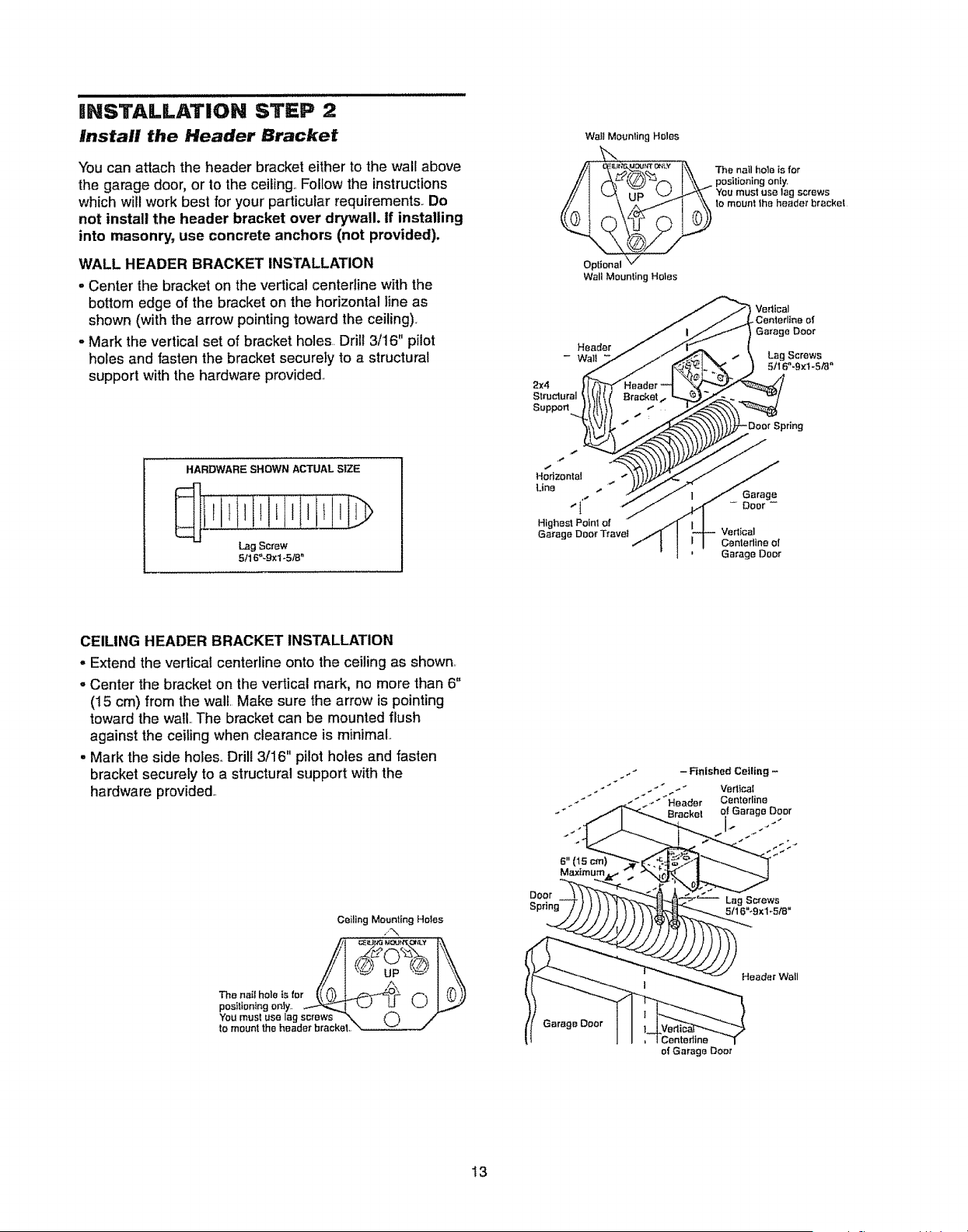
INSTALLATION STEP 2
Install the Header Bracket
You can attach the header bracket either to the wall above
the garage door, or to the ceiling.. Folfow the instructions
which will work best for your particular requirements. Do
not install the header bracket over drywall. If installing
into masonry, use concrete anchors (not provided).
WALL HEADER BRACKET INSTALLATION
o Center the bracket on the vertical centedine with the
bottom edge of the bracket on the horizontal line as
shown (with the arrow pointing toward the ceiling).
- Mark the vertical set of bracket holes.. Drill 3/16" pilot
holes and fasten the bracket securely to a structural
support with the hardware provided.,
HARDWARE SHOWN ACTUAL SIZE
................iLIlril i,)
Lag Screw
5/16"-9×1-5/8"
Wall Mounting Holes
The nail hole is for
positioning only,
You must usa lag screws
to mount 1he header bracket
Wall Mounting Holes
Header/_/
-
Struclural _/[lt( Bracket.,..
tttk}! .,.
m. ""
Highest Point of /
Garage Door TraveI """_" I
/ _ VazttcaI
/ _LCenterlina of
/ t Garage Doer
. t \ Lag Screws
_I._ I _It6"._,:1-s,_"
I_P_..--Verlical
i I Centadine of
Garage Door
CEILING HEADER BRACKET INSTALLATION
= Extend the vertical centerline onto the ceiling as shown,
° Center the bracket on the vertical mark, no more than 6"
(15 cm) from the wall. Make sure the arrow is pointing
toward the wall..The bracket can be mounted flush
against the ceiling when clearance is minimal..
• Mark the side holes.. Drill 3/16" pilot holes and fasten
bracket securely to a structural support with the
hardware provided..
Ceiling Mounting Hotes
up
positlontngonty.. _ I '--J u _._i 1
You mosl use lag screws _'.. (_
to mount the header bracket,,
Door
. _ - - Finished Ceiling -
-" "_ _--" Header Centorline
Bracket o! Garage Door
6" (15cm)
Maximum
Header Wall
Garage Door
i Centedine
of Garage Door
13
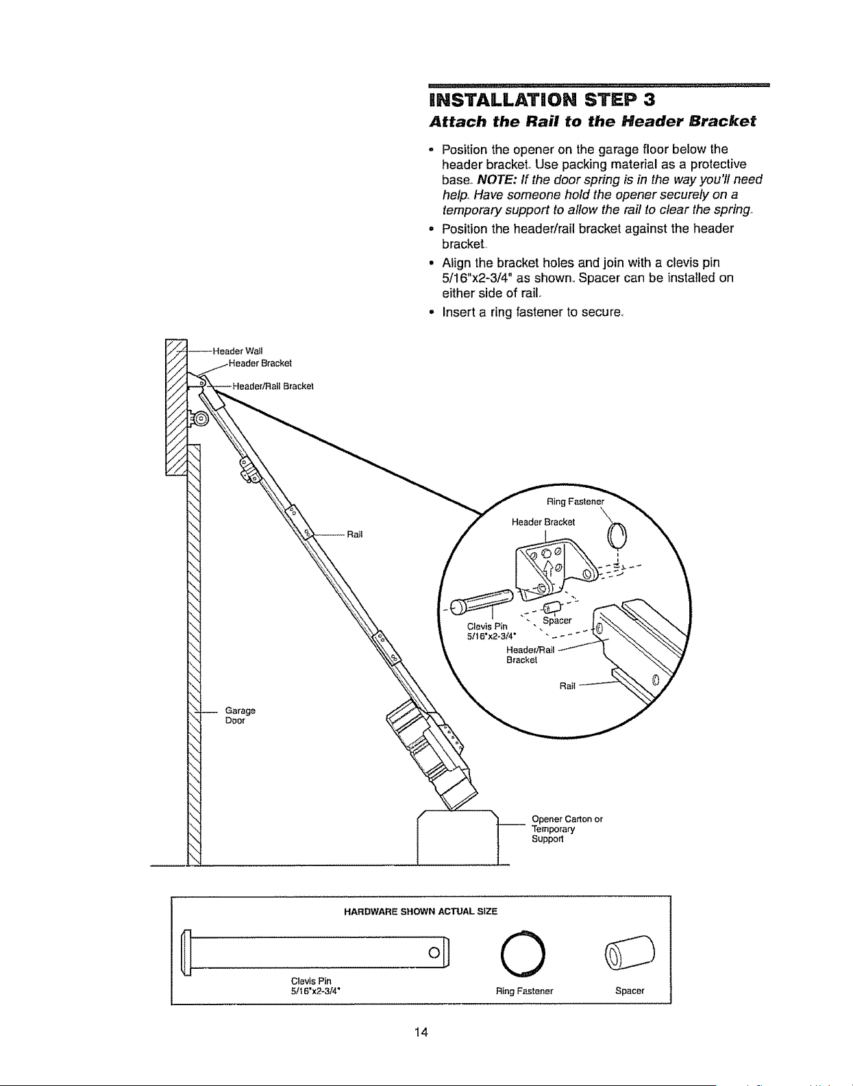
- Positiontheopeneronthegaragefloorbelowthe
headerbracket,,Usepackingmaterialasa protective
base.,NOTE: If the door spring is in the way you'll need
help.,Have someone hold the opener securely on a
temporary support to allow the rail to clear the spring
- Position the header/rail bracket against the header
bracket..
Align the bracket holes and join with a clevis pin
5/16"x2-3/4" as shown., Spacer can be installed on
either side of rail
Insert a ring fastener to secure,,
Ring Fastener
Header Bracket
Garage
Door
I l Opener Carton or
-- Temporary
Support
HARDWARE SHOWN ACTUAL SIZE
oD 0
Clevis Pin
5/16"x2_3/4" Ring Fastener Spacer
!4
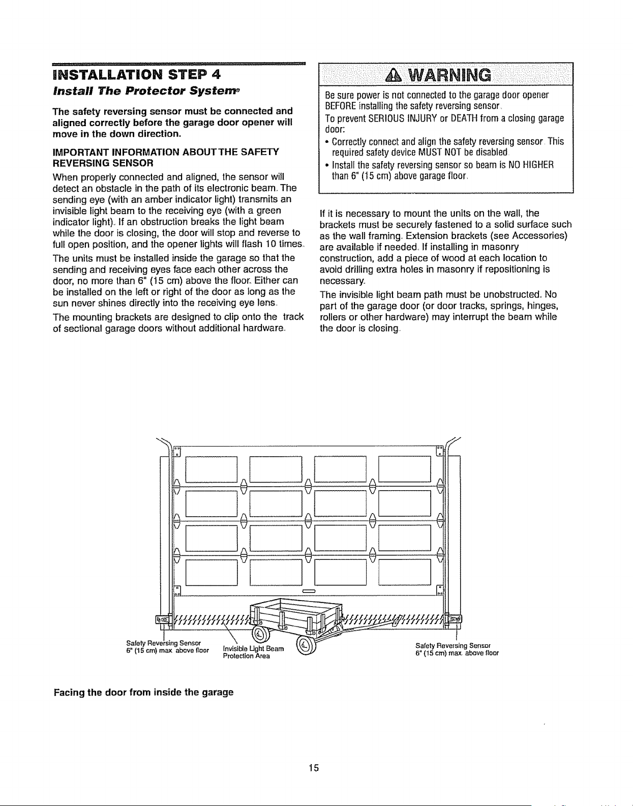
|NSTALLATION STEP 4
Install The Protector System_
The safety reversing sensor must be connected and
aligned correctly before the garage door opener will
move in the down direction.
IMPORTANT INFORMATION ABOUTTHE SAFETY
REVERSING SENSOR
When properly connected and aligned, the sensor will
detect an obstacle in the path of its electronic beam. The
sending eye (with an amber indicator light) transmits an
invisible light beam to the receiving eye (with a green
indicator light).. If an obstruction breaks the light beam
while the door is closing, the door will stop and reverse to
full open position, and the opener lights will flash 10 times..
The units must be installed inside the garage so that the
sending and receiving eyes face each other across the
door, no more than 6" (15 cm) above the floor. Either can
be installed on the left or right of the door as long as the
sun never shines directly into the receiving eye lens.
The mounting brackets are designed to clip onto the track
of sectional garage doors without additional hardware.
Besure power is not connectedto the garagedoor opener
BEFOREinstallingthe safety reversingsensor.
To preventSERIOUSINJURYor DEATHfrom a closing garage
door:
• Correctlyconnectand align the safety reversingsensor This
requiredsafetydevice MUSTNOTbe disabled
, install the safetyreversingsensor so beamis NOHIGHER
than 6" (15 cm) abovegaragefloor.
If it is necessary to mount the units on the wall, the
brackets must be securely fastened to a solid surface such
as the wall framing.. Extension brackets (see Accessories)
are available if needed If installing in masonry
construction, add a piece of wood at each location to
avoid drilling extra holes in masonry if repositioning is
necessary.
The invisible light beam path must be unobstructed.. No
part of the garage door (or door tracks, springs, hinges,
rollers or other hardware) may interrupt the beam while
the door is closing..
Safety Reve Sensor
6" (t 5 crn} max above Itoor lnv{sfble Ught Beam
Proleclion Area
Safety Reversing Sensor
6" (!5 cm) max above floor
Facing the door from inside the garage
15
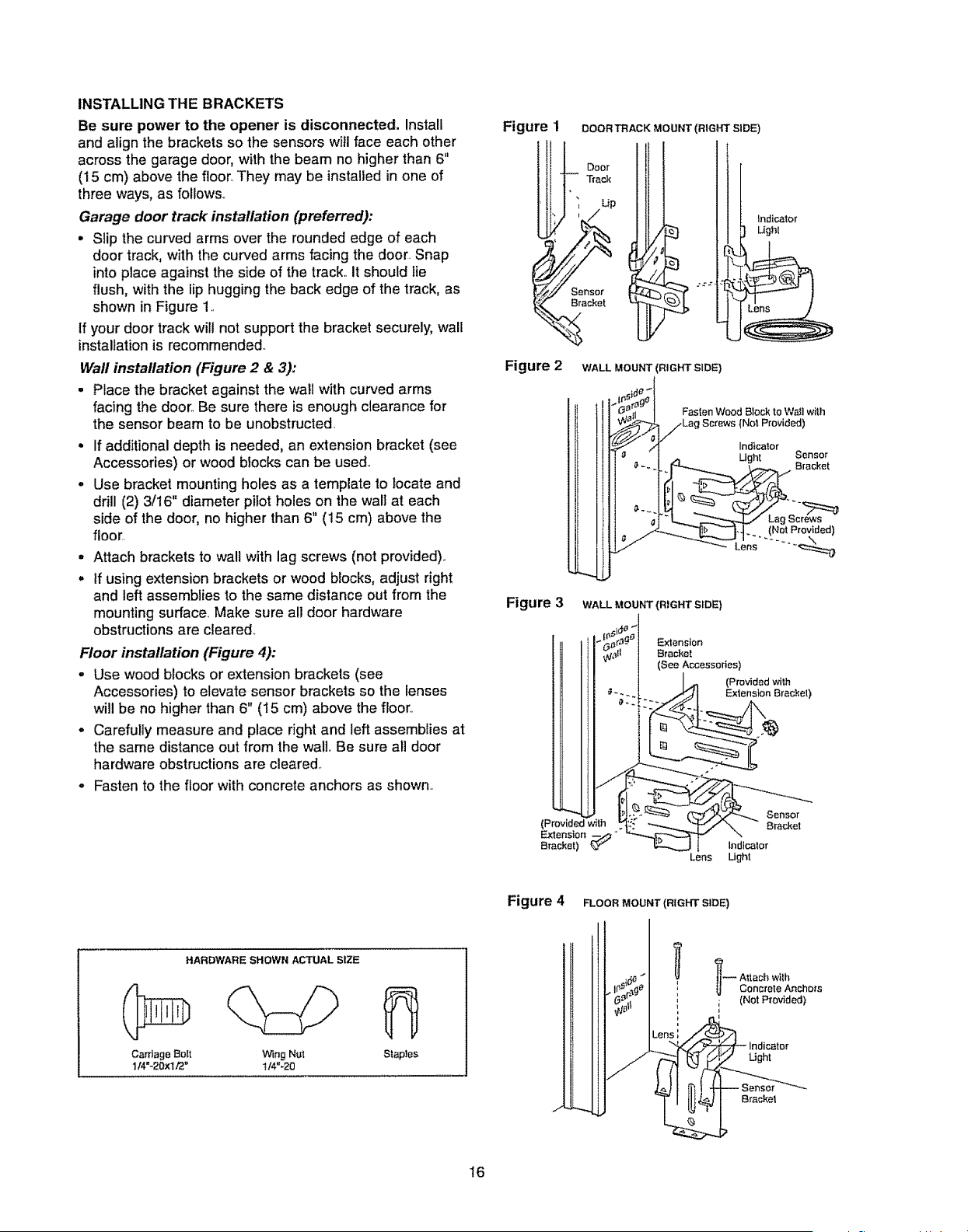
INSTALLING THE BRACKETS
Be sure power to the opener is disconnected. Install
and align the brackets so the sensors will face each other
across the garage door, with the beam no higher than 6"
(15 cm) above the floor,.They may be installed in one of
three ways, as follows..
Garage door track installation (preferred):
• Slip the curved arms over the rounded edge of each
door track, with the curved arms facing the door. Snap
into place against the side of the track. It should lie
flush, with the lip hugging the back edge of the track, as
shown in Figure 1..
If your door track will not support the bracket securely, wall
installationis recommended..
Wall installation (Figure 2 & 3):
• Place the bracket against the wall with curved arms
facing the door.. Be sure there is enough clearance for
the sensor beam to be unobstructed.
If additional depth is needed, an extension bracket (see
Accessories) or wood blocks can be used..
Use bracket mounting holes as a template to locate and
drill (2) 3/16" diameter pilot holes on the wall at each
side of the door, no higher than 6" (15 cm) above the
floor..
o
Attach brackets to wall with lag screws (not provided)..
tf using extension brackets or wood blocks, adjust right
and left assemblies to the same distance out from the
mounting surface.,Make sure all door hardware
obstructions are cleared..
Floor installation (Figure 4):
- Use wood blocks or extension brackets (see
Accessories) to elevate sensor brackets so the lenses
will be no higher than 6" (15 cm) above the floor..
. Carefully measure and place right and left assemblies at
the same distance out from the wall. Be sure all door
hardware obstructions are cleared..
o Fasten to the floor with concrete anchors as shown..
Figure 1 DOOR TRACK MOUNT (RIGHT SIDE)
Figure 2 WALL MOUNT (RIGHT SIDE}
Indicator
IJghl
01_'n I Fasten Wood Block to Wa_]with
_Lag Screws (Not Provided)
i _ Ught Sensor
_.., _ , Bracket
_'_;_-_--__1_.--lq_ (Not o "de)
Lens _" _--_
Figure 3 WALL MOUNT (RIGHT SIDE)
Extensien
Bracket
(See Accessories)
(Provided with
Extension Bracket)
(Provided with
Extension .._,<,_"
Bracket)
Lens
Sensor
8racket
Indicator
Ught
Figure 4 FLOOR MOUNT (RIGHT SIDE)
HARDWARE SHOWN ACTUAL SIZE
C_rdage Bolt Wlng Nut
114"-20x!/2" t/4"-20
J
, _ Concrete Anchors
"(39'_ i i (Not Provided)
Lens I
__ Indicator
16
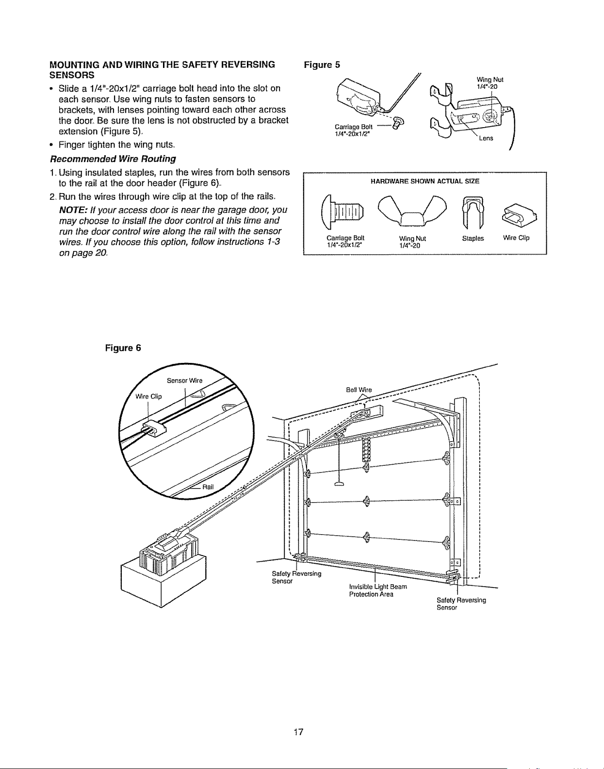
MOUNTING AND WIRING THE SAFETY REVERSING
SENSORS
• Slide a 1/4"-20xl/2" carriage bolt head into the slot on
each sensor.. Use wing nuts to fasten sensors to
brackets, with lenses pointing toward each other across
the door..Be sure the lens is not obstructed by a bracket
extension (Figure 5)..
° Finger tighten the wing nut&
Recommended Wire Routing
1..Using insulatedstaples, run the wires from both sensors
to the rail at the door header (Figure 6).
2 Run the wires through wire cIip at the top of the rails.
NOTE: if.your access door is near the garage door, you
may choose to install the door control at this time and
run the door control wire along the raft with the sensor
wires..If you choose this option, follow instructions 1-3
on page 20°
Figure 5
Wing Nut
Cai'riage Bolt
lI4"-20xt/2"
HARDWAR_ SHOWN ACTUAL SIZE
Wing Nut Slapl_s
1/4"-20
Wire Clip
Figure 6
Be1)Wire ..--'" I
.J/ !
-{ i
Safe I
Sensor I _'_'N ....
Invisible Ughl Beam
Protection Area
Safely Reve/sincj
Sensor
17
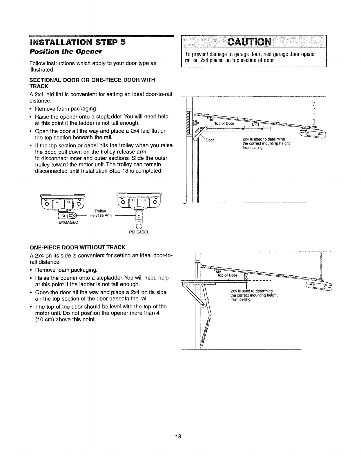
mNSTALLATiON STEP 5
Position the Opener
Follow instructions which apply to your door type as
illustrated
SECTIONAL DOOR OR ONE-PIECE DOOR WITH
TRACK
A 2x4 laid flat is convenient for setling an ideal door-to-rail
distance,.
,, Remove foam packaging
- Raise the opener onto a stepladder..You will need help
at this point if the ladder is not tall enough.
• Open the door all the way and place a 2x4 laid flat on
the top section beneath the rail..
• If the top section or panel hits the trolley when you raise
the door, pull down on the trolley release arm
to disconnect inner and outer sections.. Slide the outer
trolley toward the motor uniL The trolley can remain
disconnected until Installation Step 13 is completed..
Trolley
Release Arm
RELEASED
ONE-PIECE DOOR WITHOUT TRACK
A 2x4 on its side is convenient for setting an ideal door-to-
rail distance°
- Remove foam packaging°
o Raise the opener onto a stepladder. You will need help
at this point if the ladder is not tall enough.
• Open the door all the way and place a 2x4 on its side
on the top section of the door beneath the rail..
• The top of the door should be level with the top of the
motor unit,.Do not position the opener more than 4"
(10 cm) above this point,.
i
2x4isusLdtodetermine
the correct mounting height
from ceiling,
18
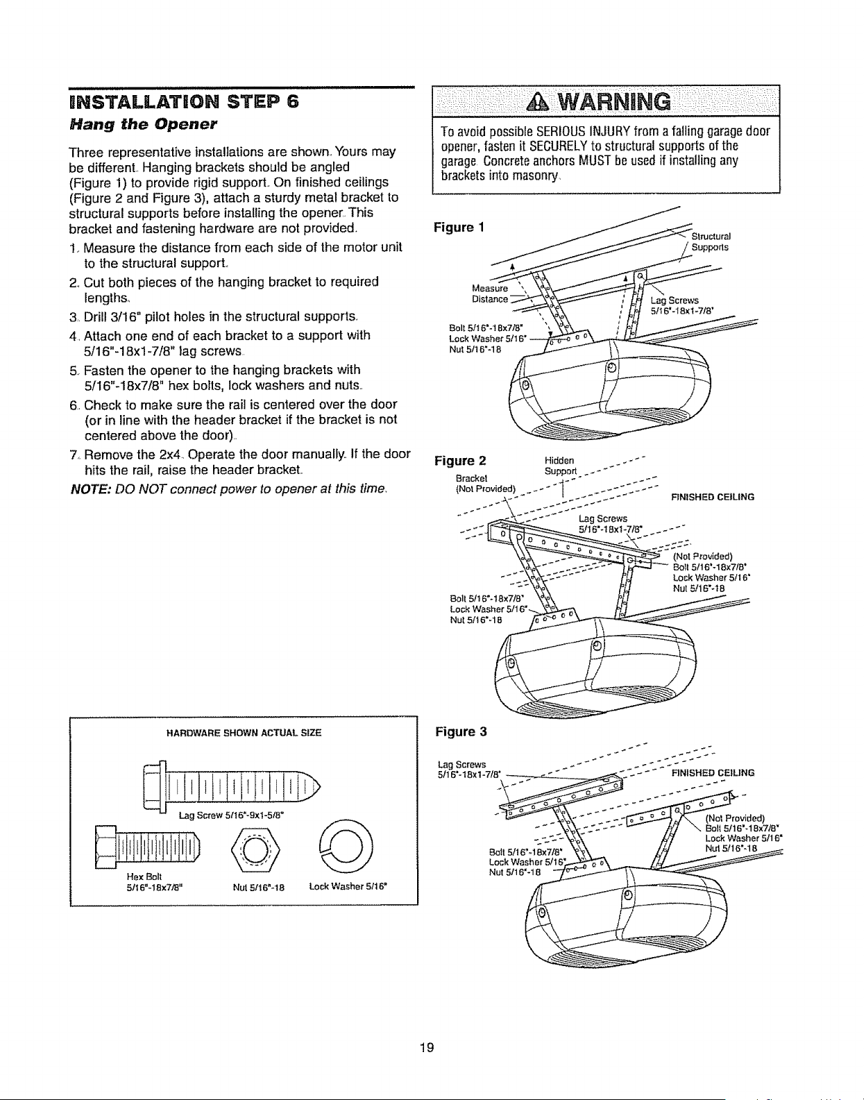
BNSTALLATIOH STEP 6
Hang the Opener
Three representative installations are shown. "Yoursmay
be different.. Hanging brackets should be angled
(Figure !) to provide rigid support.. On finished ceilings
(Figure 2 and Figure 3), attach a sturdy metal bracket to
structural supports before installing the opener. This
bracket and fastening hardware are not provided.
1. Measure the distance from each side of the motor unit
to the structural support.,
2.,Cut both pieces of the hanging bracket to required
lengths_
3. Drill 3/16" pilot holes in the structural supports..
4. Attach one end of each bracket to a support with
5/16"-18xl -7/8" lag screws
5. Fasten the opener to the hanging brackets with
5/16"-18x7/8" hex bolts, lock washers and nuts..
6..Check to make sure the rail is centered over the door
(or in line with the header bracket if the bracket is not
centered above the door)..
7..Remove the 2x4_ Operate the door manually.. If the door
hits the rail, raise the header bracket..
NOTE: DO NOT connect power to opener at this time.
Toavoid possibleSERIOUSINJURYfrom afalling garagedoor
opener,fasten it SECURELYto structural supports of the
garage ConcreteanchorsMUSTbe used if installingany
bracketsinto masonry.
Figure 1
Belt 5/I 6"-18x7/8"
Nul 5It8"-1 8
Lag Screws
51t6"-18xl -7/8'
Bolt6/t 6"-18x7/8"
Nut 5/!6"-18
RNISHED CEILING
(Not P_'ovided)
Boll 5/16'-18x7/8"
Lock Washer 5/16'
Nut 5/16"_t 6
HARDWARE SHOWN ACTUAL SIZE
!o!i!!!I!,!i!!!.!
Hex Boll
5tt 6"-18x7,"8" Nul 51t6"-18 Lock Washer 5It 6"
Figure 3
Lag Screws
5/16"- t 6x 1-7/8"
-" - - " FINISHED CEILING
_ _._"
Bott 5!16"_18x718'
Lock Washer 5/! 6
N_t 5/t 6'-18
(No_Provided)
Bolt 5/t 6'-18x7/8 _
Lock Washer 5/16 =
Nut 5116"-16
19
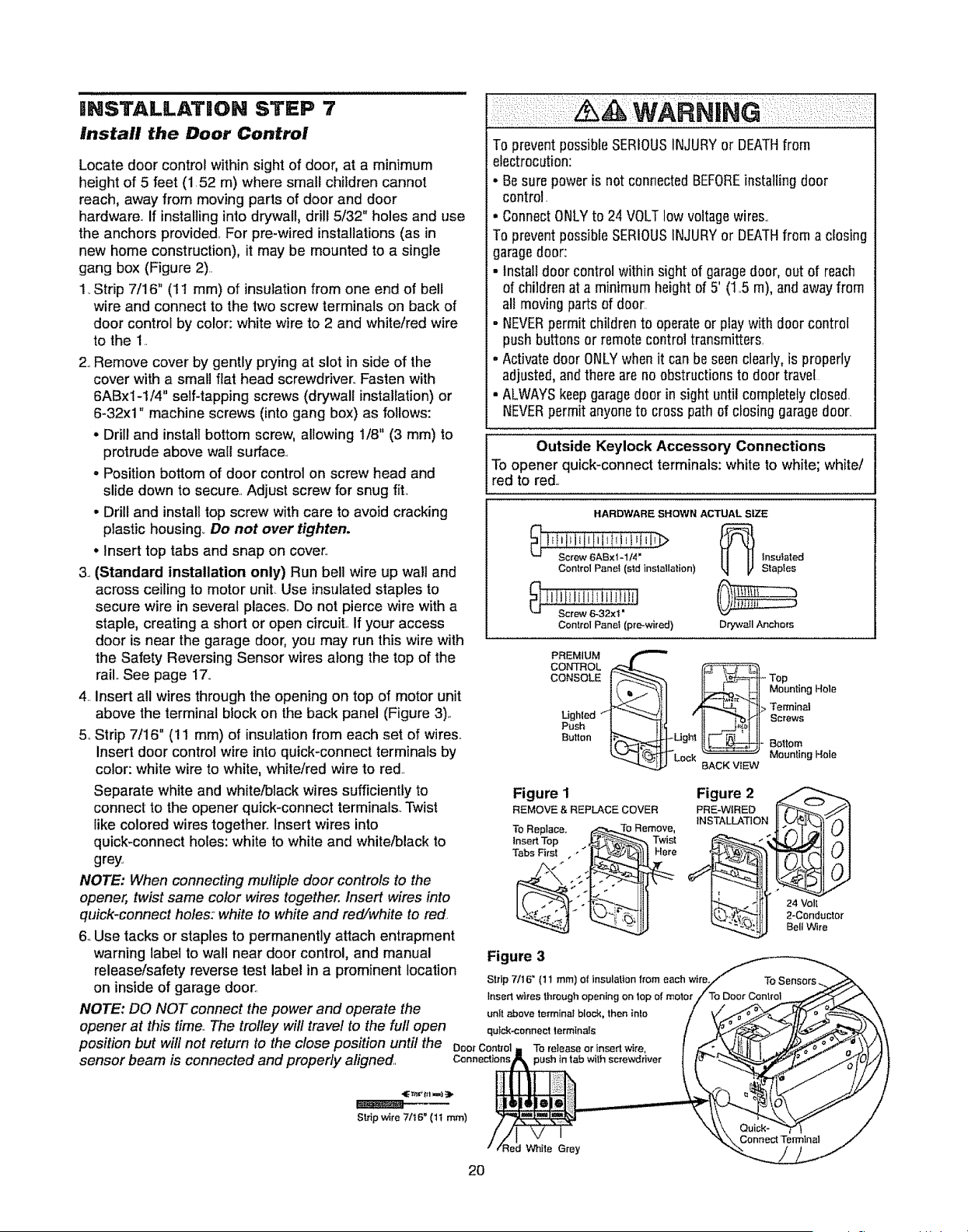
mNSTALLATION STEP 7
Install the Door Control
Locate door control within sight of door, at a minimum
height of 5 feet (1.52 m) where small children cannot
reach, away from moving parts of door and door
hardware., if installing into drywall, drill 5/32" holes and use
the anchors provided.. For pre-wired installations (as in
new home construction), it may be mounted to a single
gang box (Figure 2)..
1_Strip 7/16" (11 mm) of insulation from one end of bell
wire and connect to the two screw terminals on back of
door control by color: white wire to 2 and white/red wire
to the 1.
2..Remove cover by gently prying at slot in side of the
cover with a small flat head screwdriver.. Fasten with
6ABx1-1/4" self-tapping screws (drywall installation) or
6-32xl" machine screws (into gang box) as follows:
• Drill and install bottom screw, allowing 1/8" (3 mm) to
protrude above wall surface_
- Position bottom of door control on screw head and
slide down to secure..Adjust screw for snug fit.
° Drill and install top screw with care to avoid cracking
plastic housing,. Do not over tighten.
• Insert top tabs and snap on cover..
3. (Standard installation only) Run bell wire up walt and
across ceiling to motor unit,.Use insulated staples to
secure wire in several places° Do not pierce wire with a
staple, creating a short or open circuit.. If your access
door is near the garage door, you may run this wire with
the Safety Reversing Sensor wires along the top of the
rail..See page 17,.
4..Insert a!l wires through the opening on top of motor unit
above the terminal block on the back panel (Figure 3).
5oStrip 7/16" (11 mm) of insulation from each set of wires..
Insert door control wire into quick-connect terminals by
color: white wire to white, white/red wire to red.
Separate white and white/black wires sufficiently to
connect to the opener quick-connect terminals. Twist
like colored wires together_ Insert wires into
quick-connect holes: white to white and white/black to
grey,
NOTE: When connecting multiple door controls to the
opener, twist same color wires together. Insert wires into
quick-connect holes: white to white and red/white to red.
6.,Use tacks or staples to permanently attach entrapment
warning label to wall near door control, and manual
release/safety reverse test label in a prominent location
on inside of garage door.
NOTE: DO NOT connect the power and operate the
opener at this time. The trolley will travel to the full open
position but will not return to the close position until the Doorcontrol
sensor beam is connected and properly aligned. Connections
To preventpossibleSERIOUSINJURYor DEATHfrom
electrocution:
• Besure power is not connectedBEFOREinstalling door
control.
• ConnectONLYto 24 VOLTlow voltagewires..
To preventpossibleSERIOUSINJURYor DEATHfrom a closing
garagedoor:
• Install door control within sight of garagedoor, out of reach
of childrenat a minimum height of 5' (1..5m), andaway from
all moving partsof door.
• NEVERpermit childrento operateor playwith door control
push buttons or remotecontrol transmitters,
° Activatedoor ONLYwhen it can be seenclearly,is properly
adjusted,andthere areno obstructionsto door travel
• ALWAYSkeepgaragedoor in sight until completelydosed
NEVERpermitanyoneto cross path of closing garagedoor_
Outside Keylock Accessory' Connections
To opener quick-connect terminals: white to white; white/
red to red..
HARDWARE SHOWN ACTUAL SIZE
Control Panel(std Installation)
Control Panel (pro-wired)
_ nsulated
SlapIes
Drywall Anchors
CONTROL
CONSOLE -_Top
Mounting Hole
Ughled >. Terminat
Push Screws
Button - Bottom
Mounting Hole
BACK ViEW
Figure I Figure 2
REMOVE & REPLACE COVER PRE-WIRED
INSTALLATION
To Replace,
Insert Top
Tabs First ,,"
Twist
Here
Figure 3
Strip 7/16" (11 mm) or' insulation from each wire
Insert wires through opening on top of motor
unlt above termina! block, then into
quick.connect terminals
To release or insert wire,
=ush tn tab wilh screwdriver
24 Volt
2-Conductor
Bell Wire
Slrip wire 7116" (t t ram)
;led White Grey
2O
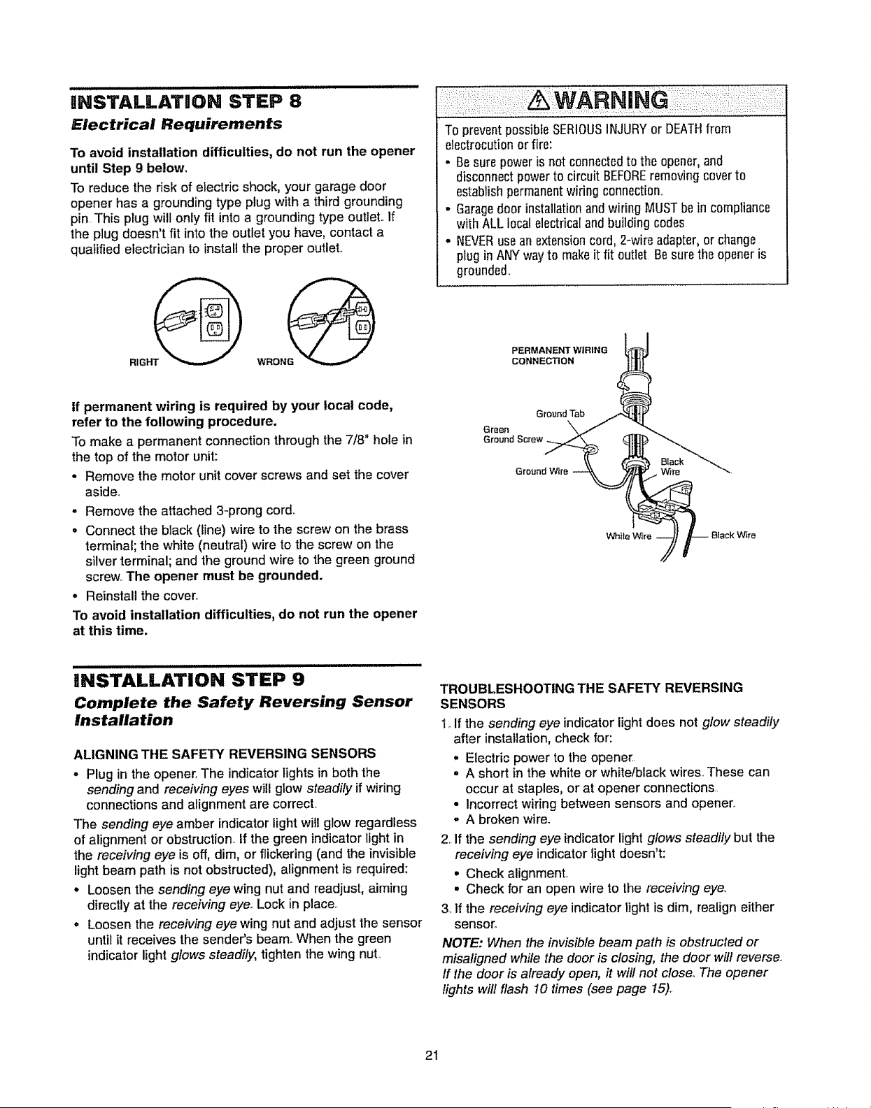
HNSTALLATHON STEP 8
Electrical Requirements
To avoid installation difficulties, do not run the opener
until Step 9 below.
To reduce the risk of electric shock, your garage door
opener has a grounding type plug with a third grounding
pin. This plug will only fit into a grounding type outlet.. If
the plug doesn't fit into the outlet you have, contact a
qualified electrician to install the proper outlet,.
To preventpossibleSERIOUSiNJURYor DEATHfrom
electrocutionor fire:
• Besure power isnot connectedto the opener,and
disconnectpower to circuit BEFOREremovingcover to
establishpermanentwiring connection.
- Garagedoor installationand wiring MUSTbe in compliance
with ALL local electrica[and building codes
• NEVERuse an extensioncord, 2-wire adapter,or change
plugin ANYwayto make it fit outlet 9e sure the opener is
grounded_
PERMANENT WIRING
CONNECTION
If permanent wiring is required by your local code,
refer to the following procedure.
To make a permanent connectionthrough the 7/8" hole in
the top of the motor unit:
• Remove the motor unit cover screws and set the cover
aside_
o Remove the attached 3-prong cord,.
= Connect the black (line) wire to the screw on the brass
terminal; the white (neutral) wire to the screw on the
silver terminal; and the ground wire to the green ground
screw,.The opener must be grounded.
° Reinstall the cover°
To avoid installation difficulties, do not run the opener
at this time,
Ground Tab
Green
Ground Screw
Ground W_re Wire
White Wlre W_re
HNSTALLATION STEP 9
Complete the Safety Reversing Sensor
installation
ALIGNING THE SAFETY REVERSING SENSORS
- Plug in the opener_The indicatorlights in both the
sending and receiving eyes will glow steadily if wiring
connectionsand alignment are correcL
The sending eye amber indicatorlight will glow regardless
of alignment or obstruction..If the green indicatorlight in
the receiving eye is off, dim, or flickering (and the invisible
lightbeam path is not obstructed), alignment is required:
• Loosen the sending eye wing nut and readjust, aiming
directlyat the receiving eye..Lock in place..
- Loosen the receiving eye wing nut and adjust the sensor
until it receives the sender's beam..When the green
indicatorlight glows steadily, tighten the wing nut.
TROUBLESHOOTING THE SAFETY REVERSING
SENSORS
1. If the sending eye indicator light does not glow steadily
after installation,check for:
• Electric power to the opener..
• A short in the white or white/black wires. These can
occur at staples, or at opener connections..
• Incorrect wiring between sensors and opener.,
. A broken wire_
2..If the sending eye indicator light glows steadily but the
receivir_g eye indicator tight doesn't:
• Check alignment,
• Check for an open wire to the receiving eye,.
3. If the receiving eye indicator light is dim, realign either
sensor.
NOTE: When the invisible beam path is obstructed or
misaligned while the door is closing, the door will reverse.
ff the door is already open, ff will not close_The opener
lights will flash 10 times (see page 15),.
21
, , ,,,,,,lUlUlUUUUl,U
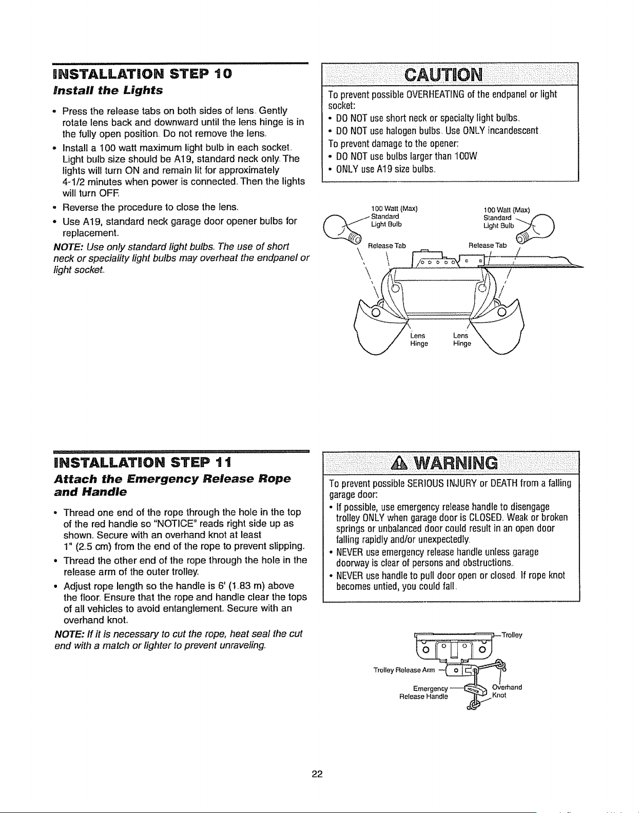
iNSTALLATION STEP t 0
Install the Lights
o Press the release tabs on both sides of lens, Gently
rotate lens back and downward until the lens hinge is in
the fully open position. Do not remove the lens.
o Install a 100 watt maximum light bulb in each socket,
Light bulb size should be A19, standard neck only. The
lights will turn ON and remain lit for approximately
4-1/2 minutes when power is connected., Then the lights
will turn OFE
o Reverse the procedure to close the lens.,
- Use A19, standard neck garage door opener bulbs for
replacement.,
NOTE: Use only standard light bulbs,, The use of short
neck or speciality light bulbs may overheat the endpanel or
light socket,,
To preventpossible OVERHEATINGof the endpanelor light
socket:
• DONOTuse short neckor specialtylight bulbs,
o DONOTuse halogenbulbs. UseONLYincandescent
To preventdamageto the opener:
° DONOTuse bulbs larger than 100W
° ONLYuseA19 sizebulbs.,
1O0 Watt (Max) 1O0 Watt (Max)
{_/Standa_'d
Ught Bulb StandaTd -....
Ught Bulb
v Release Tab Release Tab "_
INSTALLATION STEP t t
Attach the Emergency Release Rope
and Handle
o Thread one end of the rope through the hole in the top
of the red handle so "NOTICE" reads right side up as
shown,. Secure with an overhand knot at least
1" (25 cm) from the end of the rope to prevent slipping,,
° Thread the other end of the rope through the hole in the
release arm of the outer trolley,
• Adjust rope length so the handle is 6' (I..83 m) above
the floor.,Ensure that the rope and handle clear the tops
of all vehicles to avoid entanglement., Secure with an
overhand knot.,
NOTE: ff it is necessary to cut the rope, heat seal the cut
end with a match or lighter to prevent unraveling..
To preventpossibleSERIOUSINJURYor DEATH from afalling
garagedoor:
• If possible,useemergencyreleasehandleto disengage
trotley ONLYwhen garagedoor is CLOSED,,Weak or broken
springs or unbalanceddoor could resultin an opendoor
failing rapidly andlor unexpectedly.
- NEVERuseemergencyreleasehandleunless garage
doorwayis clearof persons andobstructions,
• NEVERuse handleto pull door open or closed. If ropeknot
becomesuntied,you could fall,
rolley
22
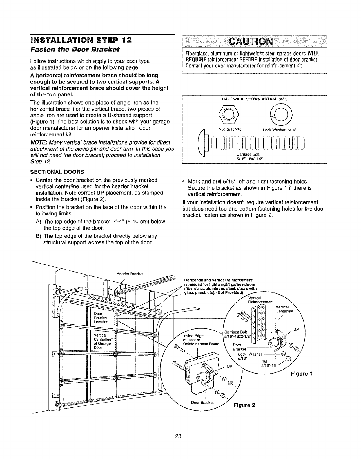
mNSTALLATmON STEP t 2
Fasten the Door Bracket
Follow instructionswhich apply to your door type
as illustrated below or on the following page..
A horizontal reinforcement brace should be long
enough to be secured to two vertical supports. A
vertical reinforcement brace should cover the height
of the top panel.
The illustrationshows one piece of angle ironas the
horizontal brace For the vertical brace, two pieces of
angle iron are used to create a U-shaped support
(Figure 1). The best solution is to check with your garage
door manufacturer for an opener installation door
reinforcement kiL
NOTE: Many vertical brace installations provide for direct
attachment of the clevis pin and door arm, In this case you
will not need the doorbracket; proceed to Installation
Step 12.
SECTIONAL DOORS
- Center the door bracket on the previously marked
vertical centerline used for the header bracket
installation,Note correct UP placement, as stamped
inside the bracket (Figure 2).
° Positionthe bracket on the face of the door withinthe
following limits:
A) The top edge of the bracket 2"-4" (5-10 cm) below
the top edge of the door.
B) The top edge of the bracket directly below any
structural support acrossthe top of the door.,
I
Fiberglass,aluminum or lightweight steel garagedoors WILL I
REQUIREreinforcementBEFOREinstallationof door bracket. I
Contactyour door manufacturerfor reinforcementkit, I
1
HARDWARE SHOWN ACTUAL SIZE
Nut 5/16"-18 Lock Washer 5/16"
Cantage Bolt
5/16"-18x2-1/2"
- Mark and drill 5/16" left and right fastening holes,
Secure the bracket as shown in Figure 1 if there is
vertical reinforcement..
If your installationdoesn't require vertical reinforcement
but does need top and bottom fastening holes for the door
bracket, fasten as shown in Figure 2,_
Header Bracket
Horizontal and vertical reinforcement
is needed for lightweight garage doors
(flbergiEass, aluminum, steel, doors with
glass panel, etc), (Not Provided)
Vertical
Centerline
/
Figure t
23
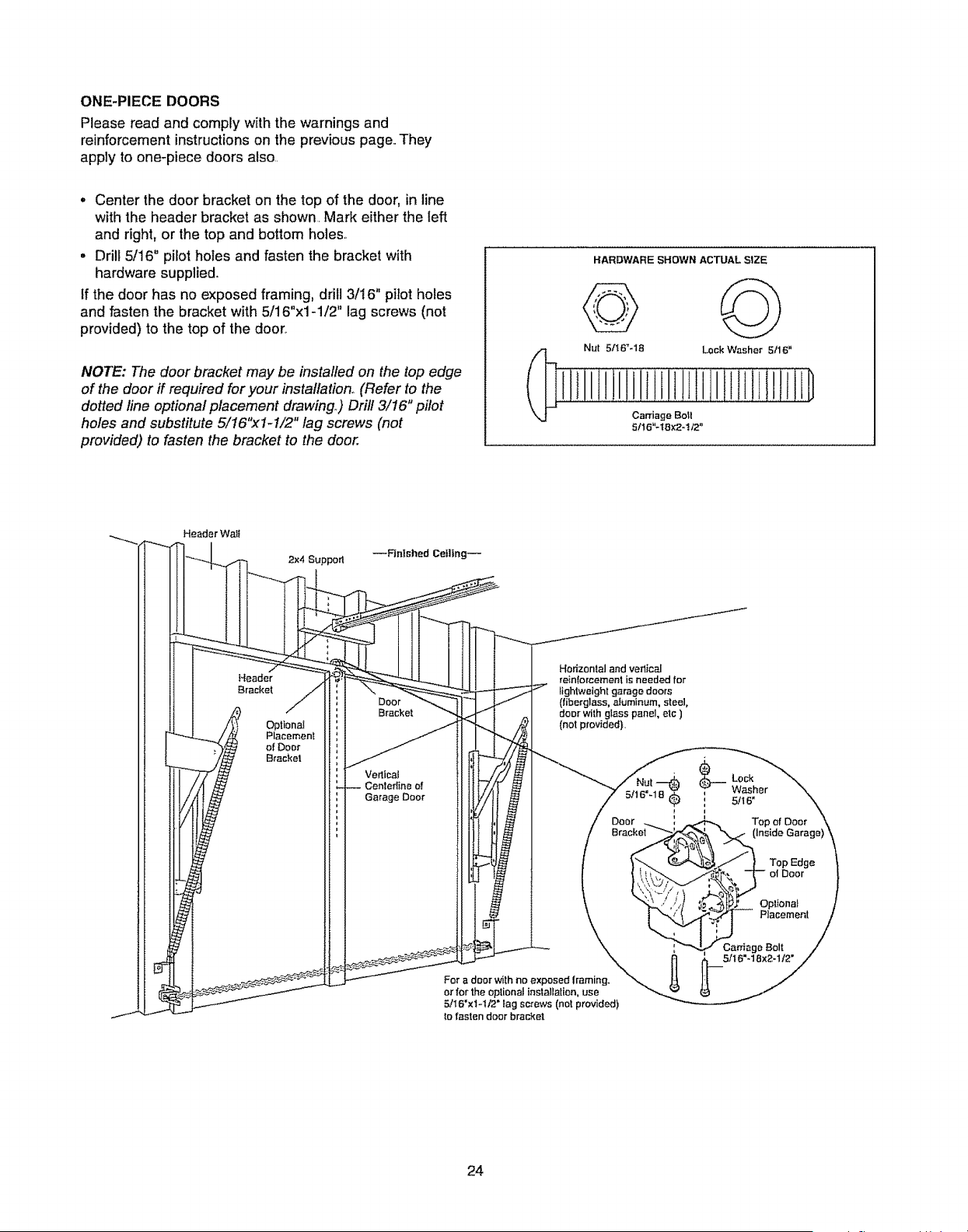
ONE-PIECEDOORS
Please read and comply with the warnings and
reinforcement instructions on the previous page,,They
apply to one-piece doors also..
o Center the door bracket on the top of the door, in line
with the header bracket as shown. Mark either the left
and right, or the top and bottom holes,_
• Drill 5/16" pilot holes and fasten the bracket with
hardware supplied,,
If the door has no exposed framing, drill 3/16" pilot holes
and fasten the bracket with 5/16"x1-1/2" lag screws (not
provided) to the top of the door,
NOTE: The door bracket may be installed on the top edge
of the door if required for your installation° (Refer to the
dotted line optional placement drawing,) Drill 3/16" pilot
holes and substitute 5/16"x1-I/2" lag screws (not
provided) to fasten the bracket to the door.
HARDWARE SHOWN ACTUAL SIZE
Nut 51t6"-18 Lock Washer 5/16"
Carriage Boll
5!16"-t8×2_!12"
Header Walt
2x4 Suppod
--F3nfshed Ceiling--
Header
Bracket
Optional
Placement
of Door
Bracke!
Door
Brecke!
Vertical
Centedine of
Garage Door
Horizontal and verlical
reinlorcement is needed for
lightweight garage doors
(tiberglass, aluminum, steel,
door wi_hglass panel, etc )
(not provided}
_Lock
Washer
: 5/I 6'
24
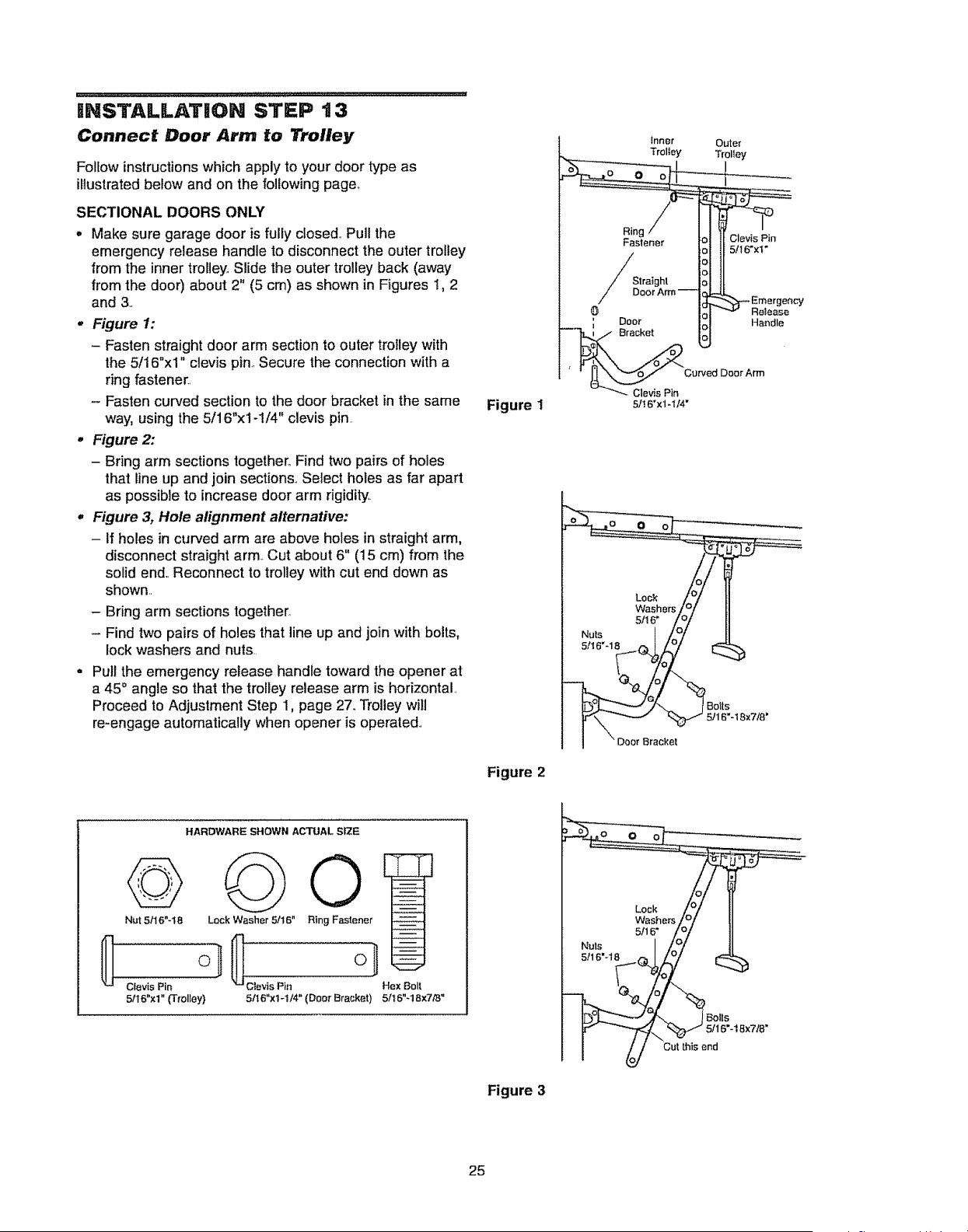
iNSTALLATiON STEP t3
Connect Door Arm to Trolley
Follow instructions which apply to your door type as
illustrated below and on the following page,,
SECTIONAL DOORS ONLY
• Make sure garage door is fully closed,, Pull the
emergency release handle to disconnect the outer trolley
from the inner trolley, Slide the outer trolley back (away
from the door) about 2" (5 cm) as shown in Figures 1, 2
and 3..
o Figure 1:
- Fasten straight door arm section to outer trolley with
the 5/16"xl" clevis pin, Secure the connection with a
ring fastener..
- Fasten curved section to the door bracket in the same
way, using the 5/16"x1-1/4" clevis pin.
° Figure 2:
- Bring arm sections together, Find two pairs of holes
that line up and join sections., Select holes as far apart
as possible to increase door arm rigidity,.
° Figure 3, Hole alignment alternative:
- If holes in curved arm are above holes in straight arm,
disconnect straight arm., Cut about 6" (15 cm) from the
solid end,,Reconnect to trolley with cut end down as
shown..
- Bring arm sections together.
- Find two pairs of holes that line up and join with bolts,
lock washers and nuts..
Pull the emergency release handle toward the opener at
a 45° angle so that the trolley release arm is horizontal,
Proceed to Adjustment Step 1, page 27. Trolley will
re-engage automatically when opener is operated..
Figure 1
Inner
Trolley
Ring
Fastener
Straight
Doo_
Bracket
Clevis Pin
5It6"x1-114"
Outer
Trolley
Clevis Pin
5/16"xt"
Curved Door Arm
Re_ease
Handle
Figure 2
HARDWARE SHOWN ACTUAL SIZE
©
Nut 5116"-18 Lock Washer 5/16" Ring Fastener
5116"xl" (Trolfey)
Hex Bolt
5116"xl-t/4"(DoorBraeket) 5/t6"4 8x7/8"
Nuts
5!16"-18
Lock
Washms
5/16"
Bolts
5/16"4 8x718"
Cut this end
Figure 3
25
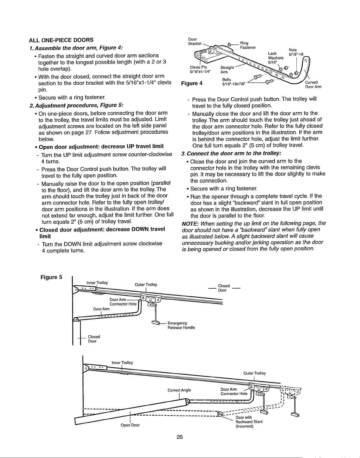
ALL ONE-PIECE DOORS
1.Assemble the door arm, Figure 4:
• Fasten the straight and curved door arm sections
together to the longest possible length (with a 2 or 3
hole overlap).
. With the door closed, connect the straight door arm
section to the door bracket with the 5/16"xl-1/4" clevis
pin.,
- Secure with a ring fastener,
2. Adjustment procedures, Figure 5:
• On one-piece doors, before connecting the door arm
to the trolley, the travel limits must be adjusted, Limit
adjustment screws are located on the left side panel
as shown on page 27,,Follow adjustment procedures
below,
• Open door adjustment: decrease UP travel limit
- Turn the UP limit adjustment screw counter-clockwise
4 turns_
Press the Door Control push button,, The trolley will
travel to the fully open position.,
- Manually raise the door to the open position (parallel
to the floor), and lift the door arm to the trolley, The
arm should touch the trolley just in back of the door
arm connector hole, Refer to the fully open trolley/
door arm positions in the illustration., If the arm does
not extend far enough, adjust the limit further, One full
turn equals 2" (5 cm) of trolley travel,
• Closed door adjustment: decrease DOWN travel
limit
- Turn the DOWN limit adjustment screw clockwise
4 complete turns,,
Door
Door AITn
- Press the Door Control push button,,The trolley will
travel to the fully closed position,,
- Manually close the door and lift the door arm to the
trolley.,The arm should touch the trolley just ahead of
the door arm connector hole. Refer to the fully closed
trolley/door arm positions in the illustration,, If the arm
is behind the connector hole, adjust the limit further,,
One full turn equals 2" (5 cm) of trolley travel°
3. Connect the door arm to the trolley:
• Close the door and join the curved arm to the
connector hole in the troliey with the remaining clevis
pin.,It may be necessary to lift the door slightly to make
the connection.
- Secure with a ring fastener
. Run the opener through a complete travel cycle,, If the
door has a slight "backward" slant in futl open position
as shown in the illustration, decrease the UP limit until
the door is parallel to the floor,
NOTE: When setting the up limit on the following page, the
door should not have a "backward" slant when fully open
as illustratedbe/ow. A slight backward sfanf wifl cause
unnecessary bucking and/or jerking operation as the door
is being opened or closed from the fully open position.
Figure 5
_.. In.ne,rj_ley Ou_.erTrotley Closed
0 or
I _ Emergency
I Release Handle
26
(Ineorrecl)
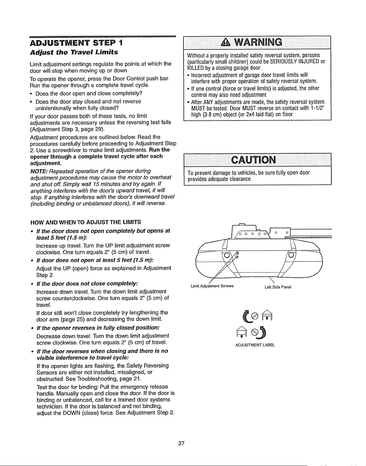
ADJUSTMENT STEP t
Adjust the Travel Limits
Limit adjustment settings regulate the points at which the
door will stop when moving up or down.
To operate the opener, press the Door Control push bar..
Run the opener through a complete travel cycle..
° Does the door open and close completely?
o Does the door stay closed and not reverse
unintentionally when fully closed?
If your door passes both of these tests, no limit
adjustments are necessary untess the reversing test fails
(Adjustment Step 3, page 29)..
Adjustment procedures are outlined beIow. Read the
procedures carefully before proceeding to Adjustment Step
2_Use a screwdriver to make limit adjustments.. Run the
opener through a complete travel cycle after each
adjustment.
NOTE: Repeated operation of the opener during
adjustment procedures may cause the motor to overheat
and shut off. Simply wait 15 minutes and try again_If
anything interferes with the door's upward travel, it wil!
stop.. If anything interferes with the door's downward travel
(including binding or unbalanced doors), it will reverse.
Without a properly installed safetyreversalsystem, persons
(particularlysmall children) could be SERIOUSLYINJUREDor
KILLEDby a closing garagedoor..
,, Incorrect adjustmentof garagedoortravel limits will
interferewith proper operationof safety reversalsystem..
• If onecontrol (force or travellimits) is adjusted,the other
control may alsoneedadjustment
• After ANY adjustmentsare made,the safety reversalsystem
MUSTbetested..Door MUSTreverseon contactwith 1-1/2"
high (3,8 cm) object (or 2x4 laid flat) on floor
To preventdamageto vehicles,besure fuIty opendoor
providesadequateclearance_
HOW AND WHEN TO ADJUSTTHE LIMITS
o if the door does not open completely but opens at
least 5 feet (1.5 m):
Increase up travel Turn the UP limit adjustment screw
clockwise.. One turn equals 2" (5 cm) of travel,.
o If door does not open at least 5 feet (1.5 m):
Adjust the UP (open) force as explained in Adjustment
Step 2..
• if the door does not close completely:
Increase down travel. Turn the down Iimit adjustment
screw counterclockwise.. One turn equals 2" (5 cm) of
travel°
If door still won't close completely try lengthening the
door arm (page 25) and decreasing the down limiL
° if the opener reverses in fully closed position:
Decrease down travel. Turn the down limit adjustment
screw clockwise, One turn equals 2" (5 cm) of travel
= If the door reverses when closing and there is no
visible interference to travel cycle:
If the opener Iightsare flashing, the Safety Reversing
Sensors are either not installed, misaligned, or
obstructed.. See Troubleshooting, page 21 ,.
Test the door for binding: Pull the emergency release
handle.. Manually open and close the door.. If the door is
binding or unbalanced, call for a trained door systems
technician. If the door is balanced and not binding,
adjust the DOWN (close) force,.See Adjustment Step 2.
O O O
Umit Adjustment Screws Left Side Panel
ADJUSTMENT LABEL
27
ADJUSTMENT STEP 2
Adjust the Force
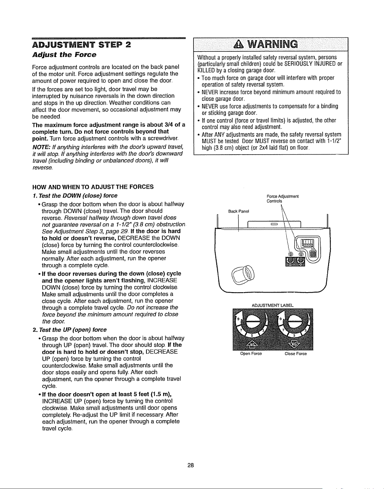
Force adjustment controls are located on the back panel
of the motor unit,.Force adjustment settings regulate the
amount of power required to open and close the door.
If the forces are set too light, door travel may be
interrupted by nuisance reversals in the down direction
and stops in the up direction.. Weather conditions can
affect the door movement, so occasional adjustment may
be needed..
The maximum force adjustment range is about 3/4 of a
complete turn. Do not force controls beyond that
point. Turn force adjustment controls with a screwdriver.
NOTE: ff anything interferes with the door's upward travel,
it will stop.,ff anything interferes with the door's downward
travel (including binding or unbalanced doors), it will
reverse..
Without a properlyinstalled safetyreversalsystem, persons
(particularlysmall children) could be SERIOUSLYINJUREDor
KILLEDby a closing garagedoor,.
° Too much force on garagedoorwill interfere with proper
operationof safetyreversalsystem..
- NEVERincreaseforce beyondminimum amount requiredto
closegaragedoor,
° NEVERuseforce adjustmentsto compensatefor a binding
or sticking garagedoor..
• If one control (force or travel limits) is adjusted,the other
control may also needadjustment..
- After ANYadjustmentsare made,the safety reversalsystem
MUSTbetested. Door MUSTreverseon contact with 1-1/2"
high (3.8 cm) object (or 2x4 laid flat) on floor.
HOW AND WHEN TO ADJUSTTHE FORCES
1.Test the DOWN (close) force
• Grasp the door bottom when the door is about halfway
through DOWN (close) travel,.The door should
reverse° Reversal halfway through down travel does
not guarantee reversal on a 1-1/2" (3..8cm) obstruction.
See Adjustment Step 3, page 29. if the door is hard
to hold or doesn't reverse, DECREASE the DOWN
(cfose) force by turning the control counterclockwise..
Make small adjustments until the door reverses
normally. After each adjustment, run the opener
through a complete cycle..
oIf the door reverses during the down (close) cycle
and the opener lights aren't flashing, INCREASE
DOWN (close) force by turning the control clockwise.
Make small adjustments until the door completes a
close cycle.. After each adjustment, run the opener
through a complete travel cycle. Do not increase the
force beyond the minimum amount required to close
the door.
2. Test the UP (open) force
• Grasp the door bottom when the door is about halfway
through UP (open) travel..The door should stop. If the
door is hard to hold or doesn't stop, DECREASE
UP (open) force by turning the control
counterclockwise. Make small adjustments until the
door stops easily and opens fully. After each
adjustment, run the opener through a complete travel
cycle,
, If the door doesn't open at least 5 feet (1.5 m),
INCREASE UP (open) force by turningthe control
clockwise.. Make small adjustments until door opens
completely. Re-adjust the UP limit if necessary. After
each adjustment, run the opener through a complete
travel cycle,.
Force Adjustment
Conlrols
Back Penet 1\_
1 I \ I
ADJUSTMENT LABEL
Open Force Close Force
28
ADJUSTMENT STEP 3
Test the Safety Reversal System
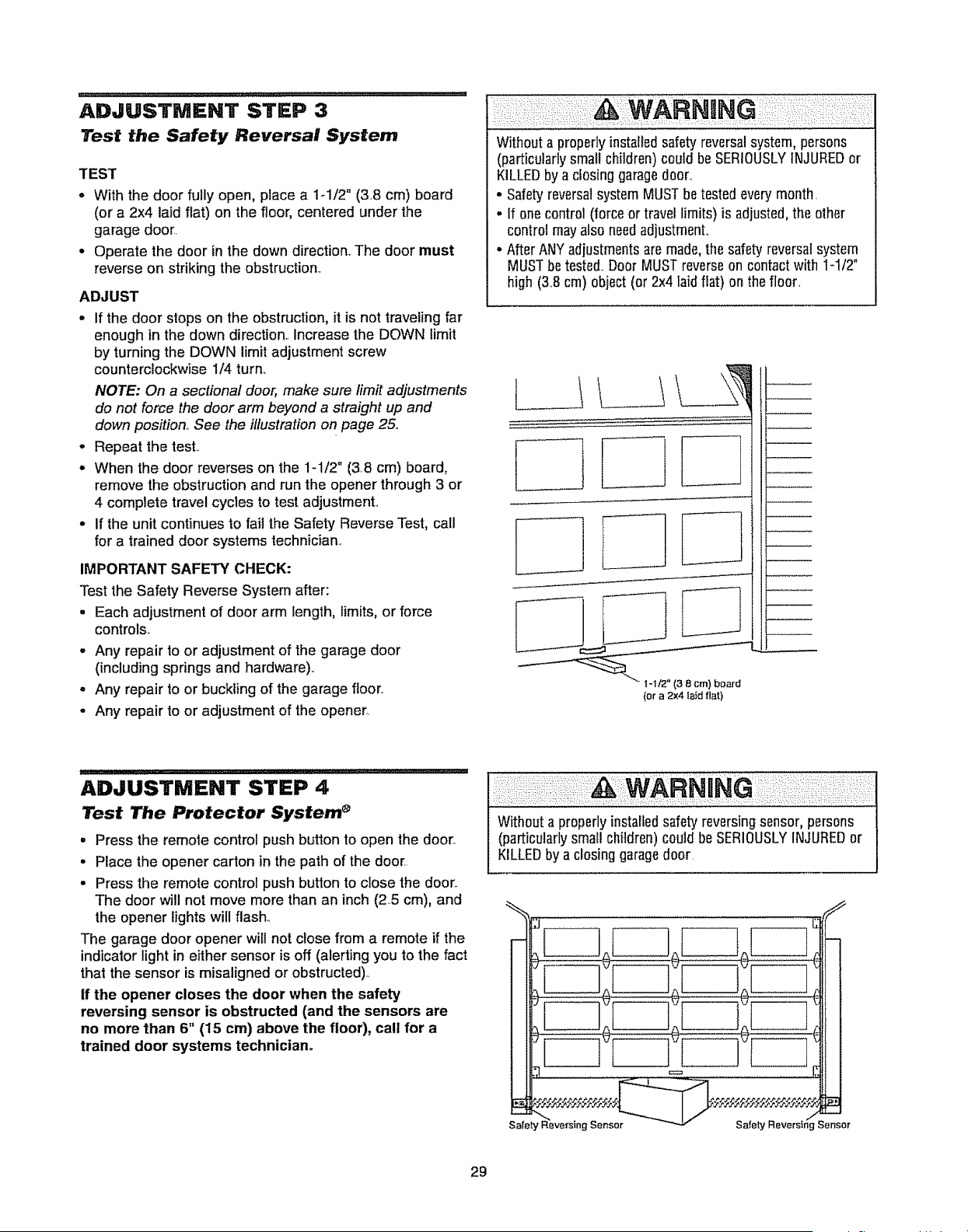
TEST
- With the door fully open, place a 1-1/2" (3..8 cm) board
(or a 2x4 laid flat) on the floor, centered under the
garage door.
• Operate the door in the down direction,. The door must
reverse on striking the obstruction..
ADJUST
° if the door stops on the obstruction, it is not traveling far
enough in the down direction.. Increase the DOWN limit
by turning the DOWN limit adjustment screw
counterclockwise 1/4 turn,.
NOTE: On a sectional door, make sure limit adjustments
do not force the door arm beyond a straight up and
down position.. See the illustration on page 25..
o Repeat the test..
° When the door reverses on the 1-1/2" (3.8 cm) board,
remove the obstruction and run the opener through 3 or
4 complete travel cycles to test adjustmenL
- If the unit continues to fail the Safety Reverse Test, call
for a trained door systems technician..
IMPORTANT SAFETY CHECK:
Test the Safety Reverse System after:
, Each adjustment of door arm length, limits, or force
controls..
° Any repair to or adjustment of the garage door
(including springs and hardware)..
° Any repair to or buckling of the garage floor.,
° Any repair to or adjustment of the opener..
iNGi
Without a properlyinstafledsafety reversalsystem,persons
(particularlysmall children) could be SERIOUSLYINJUREDor
KILLEDby a dosing garagedoor.
• Safetyreversalsystem MUSTbetested everymonth.
. tf onecontrol (forceor travetlimits) is adjusted,the other
control may also needadjustment,.
° After ANYadjustmentsaremade,the safety reversalsystem
MUSTbetested. Door MUSTreverseon contact with 1-1!2"
high (38 cm) object(or 2x4 laid flat) on the floor.
(or a 2x4 _aid flat)
ADJUSTMENT STEP 4
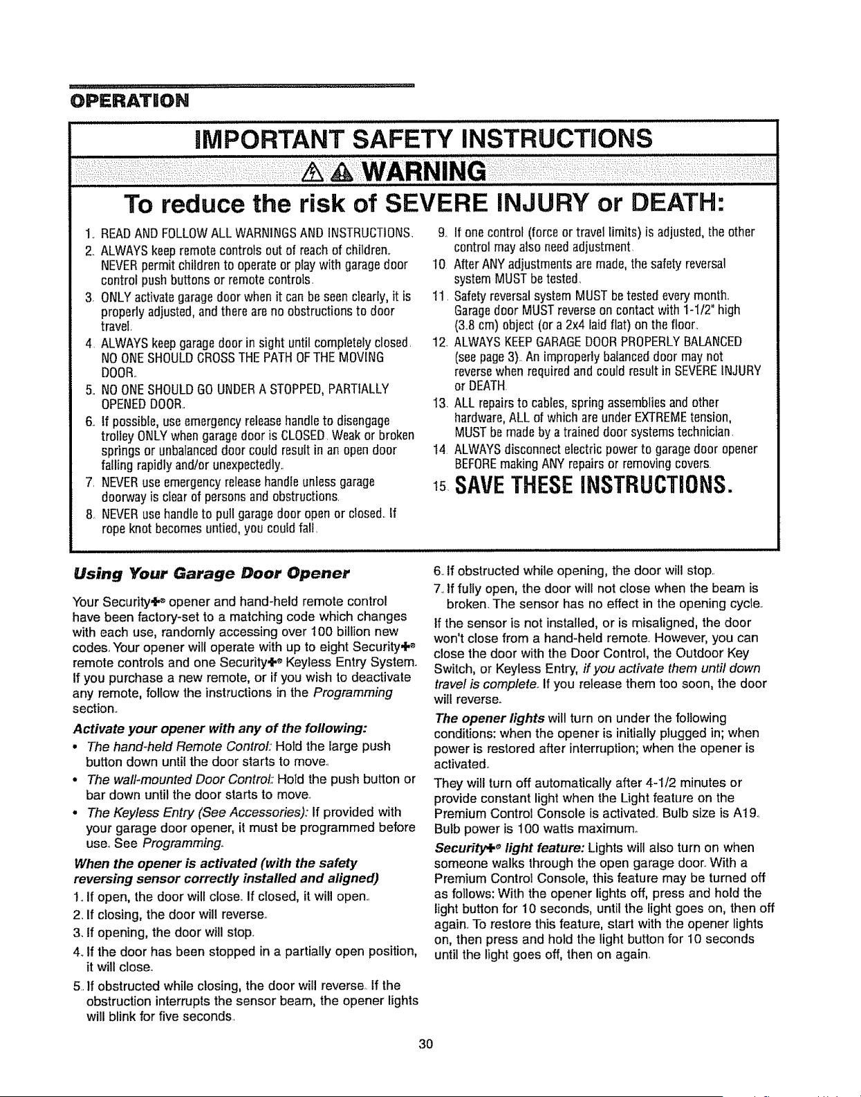
Test The Protector System _
° Press the remote control push button to open the door,.
• Place the opener carton in the path of the door.
• Press the remote control push button to close the door.,
The door will not move more than an inch (2..5cm), and
the opener lights will flash.
The garage door opener will not close from a remote if the
indicator light in either sensor is off (alerting you to the fact
that the sensor is misaligned or obstructed)..
if the opener closes the door when the safety
reversing sensor is obstructed (and the sensors are
no more than 6" (15 cm) above the floor), call for a
trained door systems technician.
Withouta properlyinstalled safetyreversingsensor, persons
(particularlysmall children)could be SERIOUSLYINJUREDor
KILLEDby aclosing garagedoor.
29
OPERATION
iMPORTANT SAFETY iNSTRUCTIONS
To reduce the risk of SEVERE INJURY or DEATH:
1.. READAND FOLLOWALLWARNINGSAND INSTRUCTIONS_
2. ALWAYSkeepremotecontrols out of reach of children.
NEVERpermit childrento operateor playwith garagedoor
control push buttons or remotecontrols.
3. ONLYactivategaragedoor when it can be seenclearly,it is
properly adjusted,andthere are no obstructionsto door
travel.
4 ALWAYSkeepgaragedoor in sight until completelyclosed.
NOONESHOULDCROSSTHEPATHOFTHE MOVING
DOOR..
5,.NOONESHOULDGOUNDERA STOPPED,PARTIALLY
OPENEDDOOR..
6.. If possible, useemergencyreleasehandleto disengage
trolley ONLYwhen garagedoor is CLOSED.Weakor broken
springs or unbalanceddoor could result in an opendoor
falling rapidlyand/or unexpectedly..
7, NEVERuse emergencyreleasehandleunlessgarage
doorwayis clear of personsand obstructions.
8 NEVERuse handleto pull garagedoor openor closed..If
ropeknot becomesuntied,you could fall.
9o If one control (force or travel limits) is adjusted,the other
control may also needadjustment.
I0 After ANYadjustmentsaremade, the safetyreversal
systemMUSTbetested
11. SafetyreversalsystemMUST betested every'month,
Garagedoor MUSTreverseon contactwith 1-I/2" high
(3.8 cm) object (or a 2x4 laid flat) on the floor..
12_ALWAYSKEEPGARAGEDOORPROPERLYBALANCED
(seepage3)._An improperlybalanceddoor maynot
reversewhen requiredand could result in SEVEREINJURY
or DEATH.
I3 ALL repairsto cables,spring assembliesand other
hardware,ALL of which areunder EXTREMEtension,
MUSTbe madeby a traineddoor systemstechnician.
t4. ALWAYSdisconnect electricpower to garagedoor opener
BEFOREmakingANY repairsor removingcovers.
I5 SAVETHESEINSTRUCTIONS.
Using Your Garage Door Opener
Your Security,iP opener and hand-held remote control
have been factory-set to a matching code which changes
with each use, randomly accessing over 100 billion new
codes.,Your opener wili operate with up to eight Security,I _
remote controls and one Security+ ®Keyless Entry System..
If you purchase a new remote, or if you wish to deactivate
any remote, follow the instructions in the Programming
section.,
Activate your opener with any of the following:
• The hand-held Remote ControL:'Hold the large push
button down until the door starts to move.,
o The wall-mounted Door Control:' Hold the push button or
bar down until the door starts to move.
• The Keyless Entry (See Accessories),: If provided with
your garage door opener, it must be programmed before
use° See Programming°
When the opener is activated (with the safety
reversing sensor correctly installed and aligned)
1. If open, the door will close. If closed, it will open..
2_If closing, the door will reverse_
3. if opening, the door will stop.,
4oIf the door has been stopped in a partially open position,
it will close.
5. If obstructed while closing, the door will reverse., tf the
obstruction interrupts the sensor beam, the opener lights
will blink for five seconds.
6. If obstructed while opening, the door will stop,.
7. If fully open, the door will not close when the beam is
broken_The sensor has no effect in the opening cycle..
If the sensor is not installed, or is misatigned, the door
won't close from a hand-held remote, However, you can
close the door with the Door Control, the Outdoor Key
Switch, or Keyless Entry, if you activate them until down
travel is complete,. If you release them too soon, the door
will reverse..
The opener lights will turn on under the fol!owing
conditions: when the opener is initiallyplugged in; when
power is restored after interruption; when the opener is
activated..
They will turn off automatically after 4-1/2 minutes or
provide constant light when the Light feature on the
Premium Control Console is activated.. Bulb size is A19.
Bulb power is 100 watts maximum_
Security+ _ light feature: Lights will also turn on when
someone walks throughthe open garage door..With a
Premium Control Console, this feature may be turned off
as follows: With the opener lights off, press and hold the
light button for 10 seconds, until the light goes on, then off
again. To restore this feature, start with the opener lights
on, then press and hold the light button for 10 seconds
until the light goes off, then on again.,
3O
Using the Wall-Mounted
Door Control
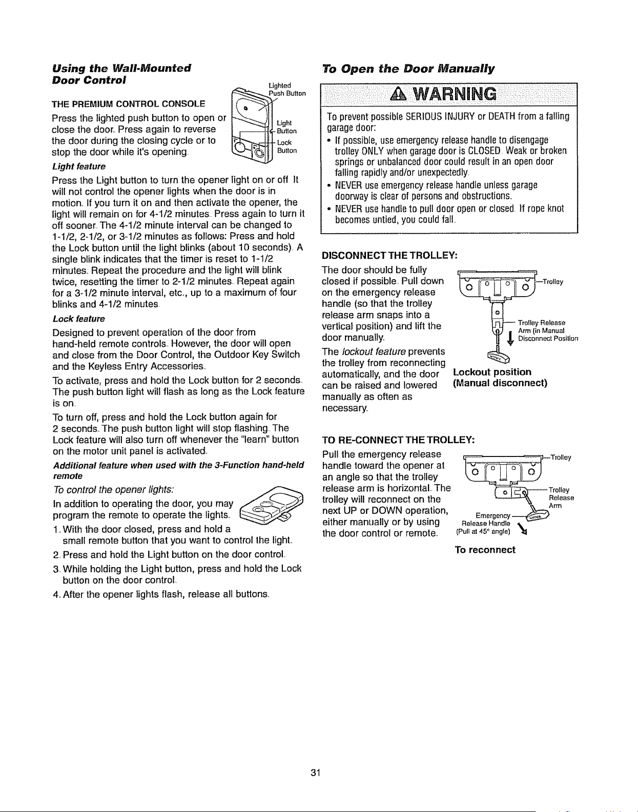
THE PREMIUMCONTROLCONSOLE
Press the lighted push button to open or
close the door,. Press again to reverse
the door during the closing cycle or to
stop the door while it's opening
Light feature
Lighted
Pus_ Button
ght
_ Button
H-Loc_
_,J Bulton
Press the Light button to turn the opener light on or off It
will not control the opener lights when the door is in
motion.,If you turn it on and then activate the opener, the
light will remain on for 4-1/2 minutes.. Press again to turn it
off sooner. The 4-1/2 minute interval can be changed to
1-1/2, 2-1/2, or 3-1/2 minutes as follows: Press and hold
the Lock button until the light blinks (about 10 seconds). A
single blink indicates that the timer is reset to 1-1/2
minutes., Repeat the procedure and the light will blink
twice, resetting the timer to 2-1/2 minutes.. Repeat again
for a 3-1/2 minute interval, etc,, up to a maximum of four
blinks and 4-1/2 minutes.
Lock feature
Designed to prevent operation of the door from
hand-held remote controls., However, the door will open
and close from the Door Control, the Outdoor Key Switch
and the Keyless Entry Accessories..
To activate, press and hold the Lock button for 2 seconds.
The push button light will flash as tong as the Lock feature
is on..
To turn off, press and hold the Lock button again for
2 seconds° The push button lightwill stop flashing, The
Lock feature will also turn off whenever the "learn" button
on the motor unit panel is activated,
Additional feature when used with the 3-Function hand-held
remote
To control the opener lights:
tn addition to operating the door, you may
program the remote to operate the lights,,
1.,With the door closed, press and hold a
small remote button that you want to control the light,.
2..Press and hold the Light button on the door control..
3..While holding the Light button, press and hold the Lock
button on the door control,.
4,,After the opener lightsflash, release all buttons,
To Open the Door Manually
To preventpossible SERIOUSINJURYor DEATHfrom a failing
garagedoor:
• If possible, useemergencyreleasehandleto disengage
trolley ONLYwhen garagedoor is CLOSEDWeakor broken
springs or unbalanceddoor could result inan opendoor
falling rapidly and/or unexpectedly,
• NEVERuseemergencyreleasehandle unlessgarage
doorway is ctear of personsand obstructions,.
• NEVERuse handleto pull door open or closed,tf rope knot
becomesuntied,you couldfall
DISCONNECT THE TROLLEY:
The door should be fuliy
closed if possible..Pull down
on the emergency release
handle (so that the trolley
release arm snaps into a
vertical position) and lift the
door manually,
The lockout feature prevents
the trolley from reconnecting
automatically, and the door
can be raised and lowered
manually as often as
necessary..
i Tr°lley
isconnect Position
Lockout position
(Manual disconnect)
TO RE-CONNECTTHE TROLLEY:
Pull the emergency release
handle toward the opener at
an angle so that the trolley
release arm is horizontal., The
trolley will reconnect on the
next UP or DOWN operation,
either manually or by using
the door control or remote.,
.............. _Trolley
Trolley
'ooso
Emergency _
Release Handle
(Pull at 45_ angle)
To reconnect
3!
CARE OF YOUR OPENER THEREMOTECONTROLBATTERY
LIMIT AND FORCE ADJUSTMENTS:
Weather conditions may cause some
minor changes in door operation
requiring some re-adjustments,
particularly during the first year of
operation.
Pages 27 and 28 refer to the limit and
force adjustments Only a screwdriver is
required, Follow the instructions
carefully
Repeat the safety reverse test
(Adjustment Step 3, page 29) after
any adjustment of limits or force.
FORCE CONTROLS
LIMIT CONTROLS
Lo
MAINTENANCE SCHEDULE
Once a Month
- Manually operate door, If it is unbalanced or binding, call
a trained door systems technician
= Check to be sure door opens & closes fully Adjust limits
and!or force if necessary (see pages 27 and 28)
. Repeat the safety reverse test Make any necessary
adjustments (see Adjustment Step 3).
Once a Year
° Oil door rollers, bearings and hinges, The opener does
not require additional lubrication° Do not grease the door
tracks
TopreventpossibleSERIOUSINJURYor DEATH:
- NEVERallow small childrennear batteries
• If batteryis swallowed,immediatelynotify doctor.
To reducerisk of fire, explosionor chemicalburn:
- ReplaceONLYwith 3V2032 coin batteries
- Do NOTrecharge,disassemble,heat above100% (212°F)
or incinerate
The lithium battery should produce power for up to
5 years_
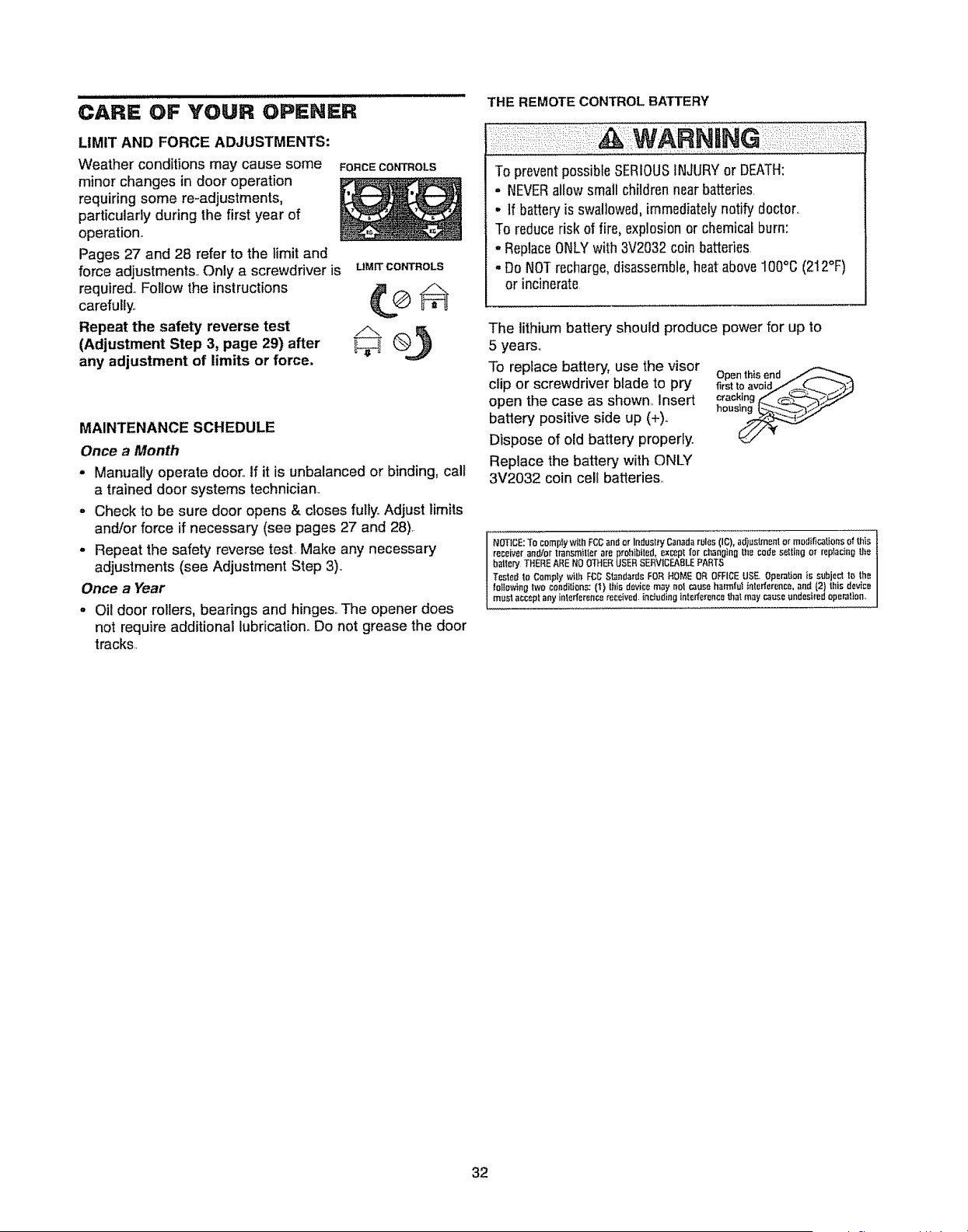
To replace battery, use the visor
clip or screwdriver blade to pry
open the case as shownMInsert
battery positive side up (+).
Dispose of old battery properly
Replace the battery with ONLY
3V2032 coin cell batteries
Open this end
first to avoid/_-.._ _'_:_
cracking E" ¢_:J_,_'-'<__.-_'/
hous_
NOTICE:To complywith FCCandor Indust;'yC,lnodarules(IC), ad)ustmentor modificationsof this
receiveran_or transmitterare prohibited,ex_pt for changin_the codesetting or replacingthe
h;dleryTHEREAREN0 OTHERUSERSERVICEABLEFARTS
Tested_oComplywilh FCCStandardsFORHOMEOR OFFICEUSE.Operationis subject to the
lo_towingtwoconditions:(1) Ihis devicemay no1causeharmfultnterfer,,_nco,and{2} thisdevice
must acceptany intederencereceived,inc_tJdinointetferance_al maycauseundesiredoperation,
32
HAVING A PROBLEM?
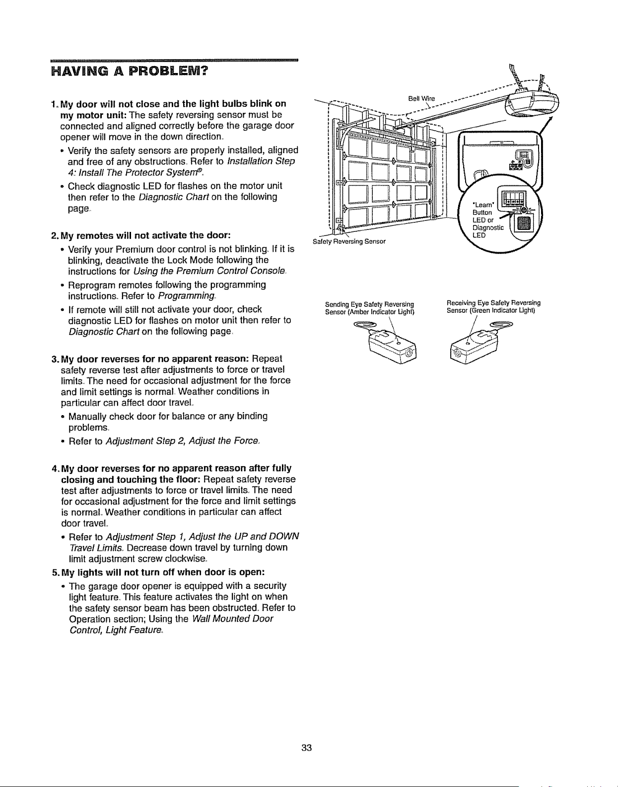
1. My door will not close and the light bulbs blink on
my motor unit: The safety reversingsensor must be
connected and aligned correctlybefore the garage door
opener will move in the down direction,,
• Verify the safety sensors are properly installed, aligned
and free of any obstructions,, Refer to installation Step
4: Install The Protector Systeme,
- Check diagnostic LED for flashes on the motor unit
then refer to the Diagnostic Chart on the following
page,,
Bell Wire
\
2. My remotes will not activate the door:
• Verify your Premium door control is not blinking,, If it is
blinking, deactivate the Lock Mode following the
instructions for Using the Premium Control Console..
. Reprogram remotes following the programming
instructions., Refer to Programming.,
• If remote will still not activate your door, check
diagnostic LED for flashes on motor unit then refer to
Diagnostic Chart on the following page,
Safe_y Reversing Sensor
Sending Eye Sa{ety Reversing
Sensor (Amber Indicator Ught)
Receiving Eye Safety Reversing
Sensor (Green Indicalor Ught)
3. My door reverses for no apparent reason: Repeat
safety reversetest after adjustments to force or travel
limits.,The need for occasional adjustment for the force
and limit settings is normal.. Weather conditions in
particular can affect door traveL,
• Manually check door for balance or any binding
problems,,
• Refer to Adjustment Step 2, Adjust the Force,
4. My door reverses for no apparent reason after fully
closing and touching the floor: Repeat safety reverse
test after adjustments to force or travel limits.,The need
for occasional adjustment for the force and limit settings
is normal Weather conditions in particular can affect
door travel
• Refer to Adjustment Step 1, Adjust the UP and DOWN
Travel Limits, Decrease down travel by turning down
limit adjustment screw clockwise,,
5. My lights will not turn off when door is open:
• The garage door opener is equipped with a security
light feature_This feature activates the light on when
the safety sensor beam has been obstructed, Refer to
Operation section; Using the Wall Mounted Door
Control, Light Feature_
33
i
Safety Reversing Sensor
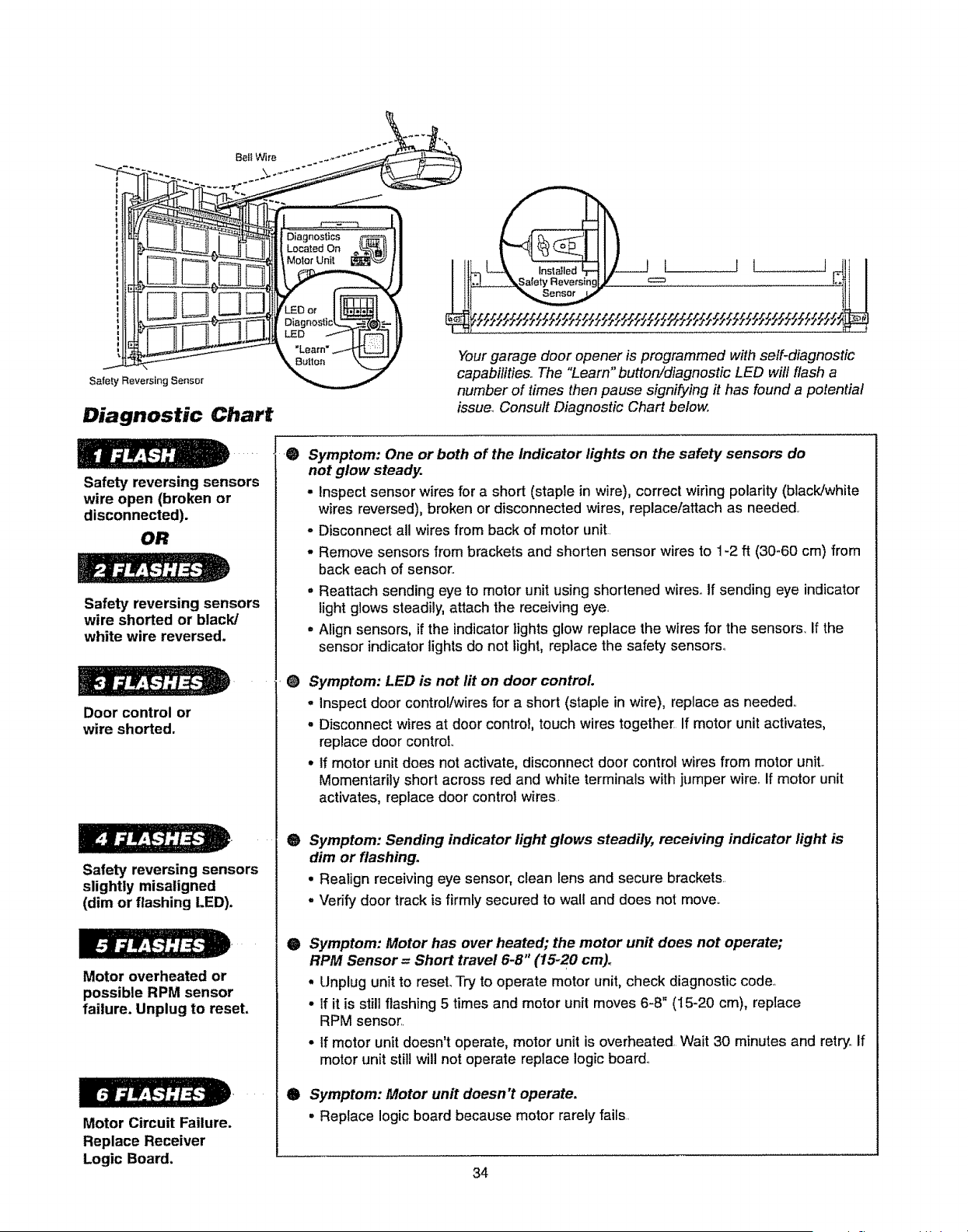
Diagnostic Chart
Sell Wire _..,_
i II II L II\
_ _t_do_ _%_II II I"'_I _,__-Ll I I I
]IIJ
_-'__ _ Yourgarage door opener is programmed w,h self-diagnostic
"_,_ _ capabilities.. The "Learn" button!diagnostic LED will flash a
number of times then pause signifying it has found a potential
issue. Consult Diagnostic Chart below.
Safety reversing sensors
wire open (broken or
disconnected).
OR
Safety reversing sensors
wire shorted or black/
white wire reversed.
Door control or
wire shorted.
Safety reversing sensors
slightly misaligned
(dim or flashing LED).
Motor overheated or
possible RPM sensor
failure. Unplug to reset,
Motor Circuit Failure.
Replace Receiver
Logic Board.
0
0
®
0
e
Symptom: One or both of the Indicator lights on the safety sensors do
not glow steady.
- Inspect sensor wires for a short (staple in wire), correct wiring polarity (black/white
wires reversed), broken or disconnected wires, replace/attach as needed,
- Disconnect all wires from back of motor unit
- Remove sensors from brackets and shorten sensor wires to 1-2 ft (30-60 cm) from
back each of sensor.
= Reattach sending eye to motor unit using shortened wires° If sending eye indicator
light glows steadily, attach the receiving eye..
= Align sensors, if the indicator lights glow replace the wires for the sensors. If the
sensor indicator lights do not light, replace the safety sensors_
Symptom: LED is not lit on door control
- Inspect door contro!iwires for a short (staple in wire), replace as needed..
- Disconnect wires at door control, touch wires together. If motor unit activates,
replace door control
• If motor unit does not activate, disconnect door control wires from motor unit..
Momentarily short across red and white terminals with jumper wire.. If motor unit
activates, replace door control wires.
Symptom: Sending indicator light glows steadily, receiving indicator light is
dim or flashing.
• Realign receiving eye sensor, clean lens and secure brackets..
- "Verifydoor track is firmly secured to walt and does not move..
Symptom: Motor has over heated; the motor unit does not operate;
RPM Sensor = Short travel 6-8" (15-20 cm)_
- Unplug unit to reset,Try to operate motor unit,check diagnostic code
• If it is still flashing 5 times and motor unit moves 6-8" (15-20 cm), replace
RPM sensor..
• If motor unit doesn't operate, motor unit is overheated. Wait 30 minutes and retry,. If
motor unit still will not operate replace logic board..
Symptom: Motor unit doesn't operate,
• Replace logic board because motor rarely faiEs,,
34
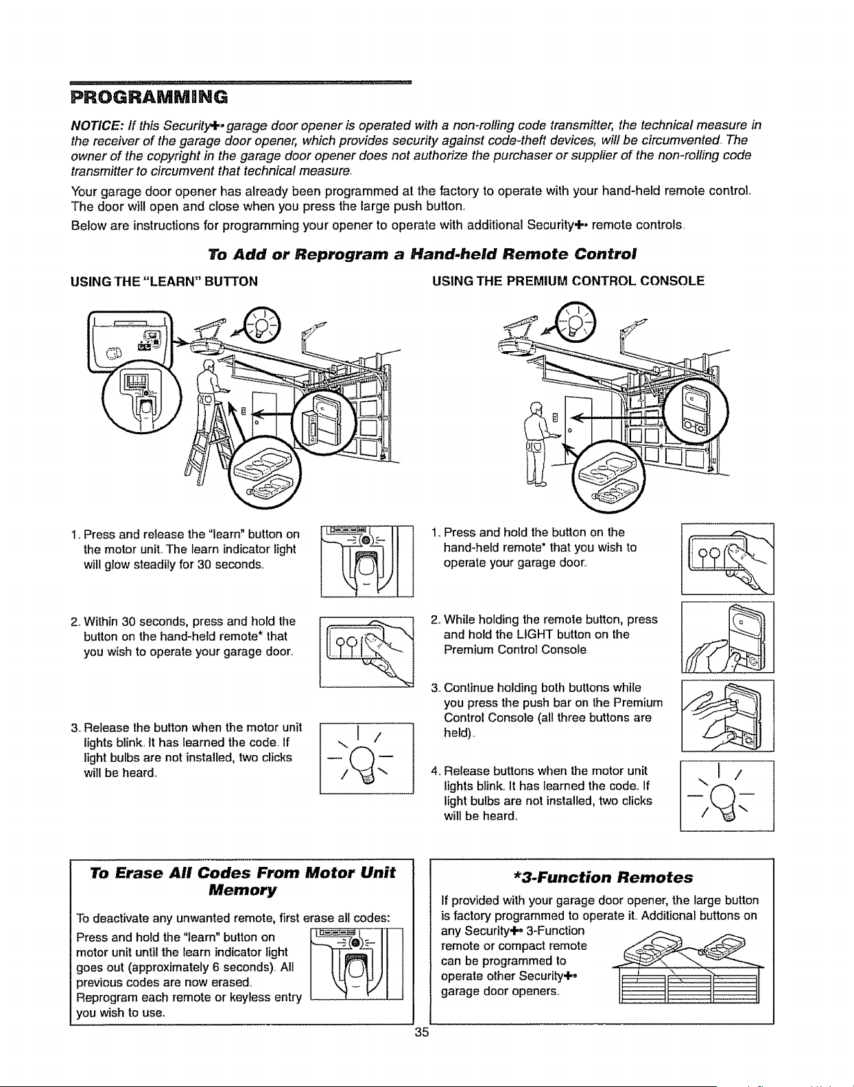
PROGRAMMNNG
NOTICE: If this Security,l,, garage door opener is operated with a non-rolling code transmitter, the technical measure in
the receiver of the garage door opener, which provides security against code-theft devices, will be circumvented The
owner of the copyright in the garage door opener does not authorize the purchaser or supplier of the non-rolling code
transmitter to circumvent that technical measure.,
Your garage door opener has already been programmed at the factory to operate with your hand-held remote control,,
The door will open and close when you press the large push button,,
Below are instructionsfor programming your opener to operate with additional Security+. remote controls,
To Add or Reprogram a Hand-held Remote Control
USING THE "LEARN" BUTTON USING THE PREMIUM CONTROL CONSOLE
1.. Press and hold the button on lhe
hand-held remote* that you wish to
operate your garage door..
1..Press and release the "learn" button on
the motor unit..The learn indicator light
will glow steadily for 30 seconds..
2. Within 30 seconds, press and hold the
button on the hand-held remote* that
you wish to operate your garage door.,
3. Release the button when the motor unit
lights blink., it has learned the code.. If
light bulbs are not installed, two clicks
will be heard.
2.. While holding the remote button, press
and hold the LIGHT button on the
Premium Control Console
3..Continue holding both buttons while
you press the push bar on the Premium
Control Console (all three buttons are
held)..
4., Release buttons when the motor unit
lights blink.. It has learned the code, If
light bulbs are not installed, two clicks
will be heard,
..,i/
To Erase All Codes From Motor Unit
Memory
To deactivate any unwanted remote, first erase all codes:
Press and hold the "learn" button on
motor unit until the learn indicator light
goes out (approximately 6 seconds)._ All
previous codes are now erased..
Reprogram each remote or keyless entry
you wish to use°
*3.Function Remotes
If provided with your garage door opener, the large button
is factory programmed to operate it. Additional buttons on
any Security+, 3-Function
remote or compact remote
can be programmed to
operate other Security+,
garage door openers,,
35
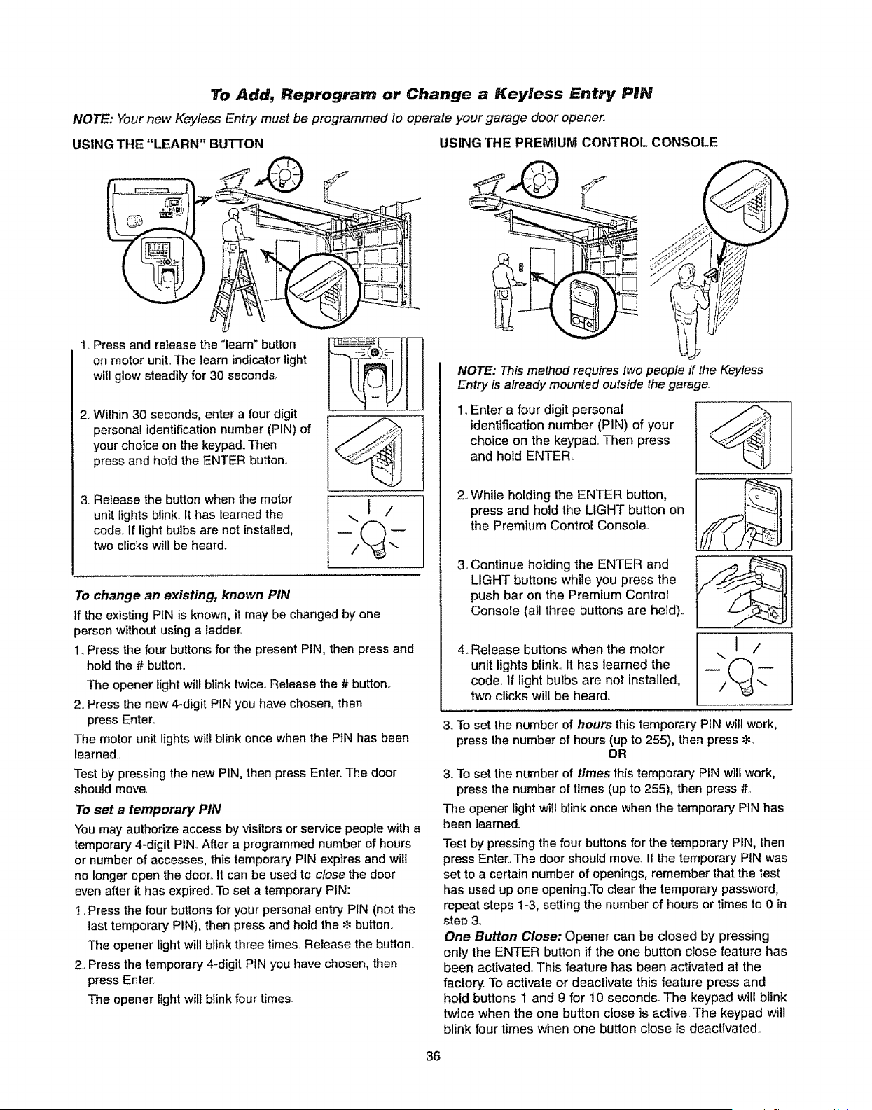
To Add, Reprogram or Change a Keyless Entry PIN
NOTE: Your new Keyless Entry must be programmed to operate your garage door opener.
USING THE "LEARN" BUTTON USING THE PREMIUM CONTROL CONSOLE
1,.Press and release the "learn" button
on motor unit..The learn indicator light
will glow steadily for 30 seconds°
2,.Within 30 seconds, enter a four digit
personal identification number (PIN) of
your choice on the keypad.. Then
press and hotd the ENTER button..
3. Release the button when the motor
unit lights blink.. It has learned the
code.. If light bulbs are not installed,
two clicks will be heard.
To change an existing, known PIN
tf the existing PIN is known, it may be changed by one
person without using a ladder
1..Press the four buttons for the present PIN, then press and
hold the # button.
The opener light will blink twice. Release the # button.
2.. Press the new 4-digit PIN you have chosen, then
press Enter,.
The motor unit lights will blink once when the PIN has been
learned.
Test by pressing the new PIN, then press Enter,. The door
should move..
To set a temporary PIN
You may authorize access by visitors or service people with a
temporary 4-digit PIN. After a programmed number of hours
or number of accesses, this temporary PIN expires and will
no longer open the door. It can be used to close the door
even after it has expired° To set a temporary PIN:
1. Press the four buttons for your personal entry PIN (not the
last temporary PIN), then press and hold the _: button,
The opener light will blink three times. Release the button,.
2.. Press the temporary 4-digit PIN you have chosen, then
press Enter.,
The opener light will blink four times_
NOTE: This method requires two people if the Keyless
Entry is already mounted outside the garage_
1..Enter a four digit personal
identification number (PIN) of your
choice on the keypad.1Then press
and hold ENTER_
2. While holding the ENTER button,
press and hold the LIGHT button on
the Premium Control Console.
,
Continue holding the ENTER and
LIGHT buttons while you press the
push bar on the Premium Contro_
Console (all three buttons are held).
.,
Release buttons when the motor
unit lights blink. It has learned the
code_If light bulbs are not installed,
two clicks will be heard.
..,I /
3oTo set the number of hours this temporary PIN will work,
press the number of hours (up to 255), then press 8:,.
OR
3..To set the number of times this temporary PIN will work,
press the number of times (up to 255), then press #.1
The opener light will blink once when the temporary PIN has
been learned_
Test by pressing the four buttons for the temporary PIN, then
press Enter., The door should move. If the temporary PIN was
set to a certain number of openings, remember that the test
has used up one opening.To clear the temporary password,
repeat steps 1-3, setting the number of hours or times to 0 in
step 3.
One Button Close: Opener can be closed by pressing
only the ENTER button if the one button close feature has
been activated. This feature has been activated at the
factory'.. To activate or deactivate this feature press and
hold buttons 1 and 9 for 10 seconds. The keypad will blink
twice when the one button close is active. The keypad will
blink four times when one button close is deactivated..
36
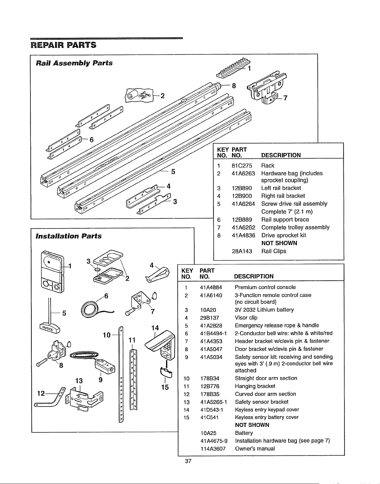
REPAIR PARTS
Rail Assembly Parts
2
5
4
3
Installation Parts
'13
10
9
14
15
KEY PART
NO. NO. DESCRIPTION
1
2
3
4
5
6
7
8
81C275 Rack
41A6263 Hardware bag (includes
sprocket coupling)
12B890 Left rail bracket
12B900 Right rail bracket
41A6264 Screw drive rail assembly
Compiete 7' (2,1 m)
12B889 Rail support brace
41A6262 Complete trolley assembly
41A4836 Drive sprocket kit
NOT SHOWN
28A143 Rail Clips
KEY PART
NO. NO. DESCRIPTION
1
2
41A4884
41A6140
3 10A20
4 29B137
5 41 A2828
6 41 B4494-1
7 41A4353
8 41A5047
9 41A5034
10 178B34
11 12B776
12 178B35
13 41A5266_1
t4 4ID543-1
15 41C54t
IOA25
41 A4675-9
114A3607
Premium control console
3-Function remote control case
(no circuit board)
3V 2032 Lithium battery
Visor clip
Emergency release rope & handle
2-Conductor bell wire: white & white/red
Header bracket w!clevis pin & fastener
Door bracket wtclevis pin & fastener
Safety sensor kit: receiving and sending
eyes with 3' (.9 m) 2-conductor bell wire
attached
Straight door arm section
Hanging bracket
Curved door arm section
Safety sensor bracket
Keyless entry keypad cover
Keyless entry battery cover
NOT SHOWN
Battery
Installation hardware bag (see page 7)
Owner's manual
37
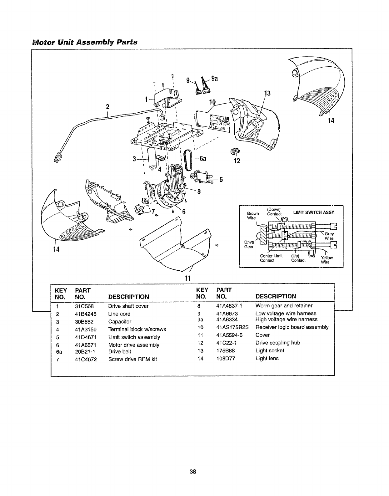
Motor Unit Assembly Parts
1
10
!
13
14
12
14
Brown
Gear
(Down)
Contact
\
LIMIT SWITCH ASSY
Center Umlt (Up) Yellow
Contact Contact Wire
KEY PART
NO, NO.
1 31C568
2 41B4245
3 30B652
4 41A3150
5 41D4671
6 41A6671
6a 20B21-1
7 4t C4672
11
DESCRIPTION
Drive shaft cover
Line cord
Capacitor
Terminat block w/screws
Limit switch assembly
Motor drive assembly
Drive belt
Screw drive RPM kit
KEY
NO.
8
9
9a
10
i1
12
13
14
PART
NO.
41A4837-1
41 A6673
4t A6334
41ASI75R2S
41A5594-6
41C22-1
175B88
108D77
DESCRIPTION
Worm gear and retainer
Low voltage wire harness
High voltage wire harness
Receiver _ogicboard assembly
Cover
Drive coupFing hub
Light socket
Light lens
38
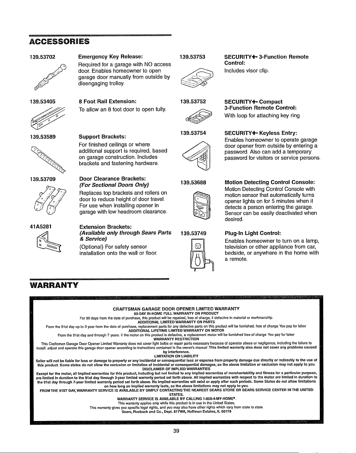
ACCESSORIES
139.53702
/
Emergency Key Release:
Required for a garage with NO access
door..Enables homeowner to open
garage door manually from outside by
disengaging trolley.
139.53753
139.53405 8 Foot Rail Extension: 139,53752
To allow an 8 foot door to open fully..
SECURITY+, 3-Function Remote
Control:
Includes visor clip,,
SECURITY+. Compact
3-Function Remote Control:
With loop for attaching key ring.
139.53754
139.53589 Support Brackets:
For finished ceilings or where
_%._..h additional support is required, based
on garage construction° includes
._ brackets and fastening hardware..
139.53709 Door Clearance Brackets:
(For Sectional Doors Only) 139.53688
Replaces top brackets and rollers on
door to reduce height of door travel.
For use when installingopener in
garage with low headroom clearance.,
41A5281 Extension Brackets:
(Available only through Sears Parts 139.5374_1
& Service)
(Optional) For safety sensor
installation onto the wall or floor,
WARRANTY
SECURITY+, Keyless Entry:
Enables homeownerto operate garage
door opener from outside by entering a
password, Also can add a temporary
passwordfor visitors or service persons.
Motion Detecting Control Console:
Motion Detecting Control Console with
motion sensor that automatically turns
opener lights on for 5 minutes when it
detects a person entering the garage,.
Sensor can be easily deactivated when
desired,
Plug-In Light Control:
Enables homeowner to turn on a lamp,
television or other appliance from car,
bedside, or anywhere in the home with
a remote..
CRAFTSMAN GARAGE DOOR OPENER LIMITED WARRANTY
gO-DAY IN.HOME FULL WARRANTY ON PRODUCT
For 90 days from the date of purchase, this product will be repafred_ fre_ of charge, if defective in mafefiai or workmanship,
ADDITIONAL LIMITEDWARRANTY ON PA_'S
From the glsl day up to 3 year from the date et purchase, repfacement parts for any delective parts on this product will bs furnished, free of charge_ YOU pay lot labor
ADDrI'tONAL LIFE3]ME LIMrFED WARRANTY ON MOTOR
From the 91st day end through 7 yearS, il the motor on this product is defective, a rep._acoment motor wi!l be lumlshe_ free or c!_arge. You pay far _abor
WARRANTY RESTRICTION
Th_s Craftsman Garage Door Opener Ltmited Warranty does not cover light bulbs or repair parts neceasa_ because of operator abuse or negligence, including the failure ta
install, adjust and operate this garage door opener according 1o instructions contained _n the owners manual This limited warranty also does not cover any problems caused
by interference,
LIMITATION ON UARtLITY
Seller w]Ii not be liable for loss or damage to property or any Incidental or consequential loss or expense from property damage due directly or IndireeUy to the use of
this produoL Some states do not allow the exclusion or limitation of incidental or consequential damages, so the above limitation or excfusloo may not apply to you.
DISCLAIMER OF IMPLIED WARRANTIES
Except for the motor, atl Implied werront_es for this product, Including but not limited to any Implied warranties of m_rchantablllty und fitness for a parttcufar purpose,
ere limited in duration to the 81st day through 3--ym_r llmltl_l warranty pedod set forth above.. All [mpfied wan'anties with respect to the motor are timLtod in duration to
the 91st day through 7-year limited warranty pedod set forth above. No tmptfed warrantees wll[ extst or apply after such pertods. Some States do not allow limitations
on how long an Irapged warranty last-s, so the above limitations may not apply to you,
FROM THE gIST DAY, WARRANTY sERVIcE IS AVAILABLE BY SIMPLY CONTACTING THE NEAREST SEARS STORE OR SEARS SERVICE CENTER IN THE UNITED
STATES.
WARRANTY SERVICE tS AVAILABLE BY CALLING 1-800-A-MY-HOMES..
Thts warranty applies only while this product is tn use in the Unitecf States.
This warranty gives you spectt_o legal rights, and you may atso have other rights which vary from state to slate,
Sears, Roebuck and Co.., DepL 817WA, Half man Estates, IL 60179
39
CONTEN DO
introducci6n 2-7
Revisi6n de los sfmbolos y t_rminos de seguridad ............ 2
Preparaci6n de ia puerta de su cochera ........................ 3
Herramientas necesadas ........................................... 3
PlanificaciSn
.....................................................
4-5
Inventario de la caja de carton .................................... 6
inventafio de piezas .............................................. 7
Montaje 8.11
Monte et riel ..................................................... 8-9
Fije el del a la unidad del motor y instale el trofe .................. 10
Fijaci6n de las m_nsulas del riel
..................................
11
lnstalaci6n 11.26
Instrucci6nes importantes para la instalaci6n ................... 11
Determine dSncle va a instalar la M_nsula del Cabezal ...... 12
instale la rn_nsula del cabezal
......................................
13
ColocaciSn del riel en la m_nsula del cabezal .................. 14
instale La Sistema de ProtecciSn ®......................... t5-17
Co!oque el abridor en posici6n
....................................
18
Cuelgue el abridor ...................................................... 19
lnstale ta unidad de contro! de la puerta ......................... 20
Requisitos para la instalaciOn el_ctrica ........................ 21
Termine la instalaciOn del sensor del sistema reversa
de seguridad ................................................... 21
Instale las luces
.......................
.............................
22
Coloque la cuerda y la rnanija de emergencia ....................... 22
Fije la m_nsuta de la puerta ...................................... 23-24
Conecte el brazo de la puerta af trole ........................ 25-26
Ajustes 27-29
Ajuste e! limite del recorrido HACIA ARRIBA y
HACIA ABAJO ....................................................... 27
Ajuste la fuerza
.........................................................
28
Pruebe el Sistema de Retroceso de Seguridad ................ 29
Pruebe la Sistema de ProtecciOn, _............................... 29
|NTRODUCCION
Operaci6n 30.34
instrucci6nes importantes de seguridad ......................... 30
COmo usar su abridor de puerta de cochera .................. 30
C6mo usar la unidad de control de la puerta .................. 3t
C6mo abrir ia puerta manualmente .......................... 31
Mantenimiento de su abridor de puerta de cochera ........... 32
Si tiene algL_nproblema ......................................... 33
Tabla de diagnOstico.............................................. 34
Como Programar el Abridor 35.36
Como agregar o reprogramar un control remoto manual ...... 35
Para borrar todos los c6digos de la memoda de la
uniclad del motor,, ..................................................... 35
Controles remotos de 3 funciones .................................. 35
C6mo agregar, reprogramar o cambiar un cSdigo
de entrada sin Ilave ...................................................... 36
Accesorios 3 7
Garantia 37
Nbmeros de Servicio Contratapa
Revisi6n de los Simbolos y T_rminos
de Seguridad
Este abridor de puerta de cochera ha siclo dise_ado y probado para un funcionamiento seguro, siempre y cuando se instale, se
pruebe, se opere y sete d_ mantenimiento como se indica en este manual, cumpliendo at pie de la letra con todas las adverlencias e
instrucciones generales aquf contenidas,
Estas advertencias y/o sfmbolos de seguridad que aparecen en
este manual le atertar_n de que existe el riesgo de una lesidn
seria o de muerte si no se siguen tas instrucciones
correspondientes, El peligro puede set el6ctrico (electrocuciSn) o
mec_nico Lea las instrucciones con mucho cuidado,,
Mec_nica
Ei_ctrica
Cuando yea esta palabra y/o s_mbolo de seguridad en este
manual, le alertar__de que existe et riesgo de dafar ia puerta de
la cochera y/o el abridor si no se siguen las instrucciones
correspondientes Lea las instrucciones con mucho cuidado,
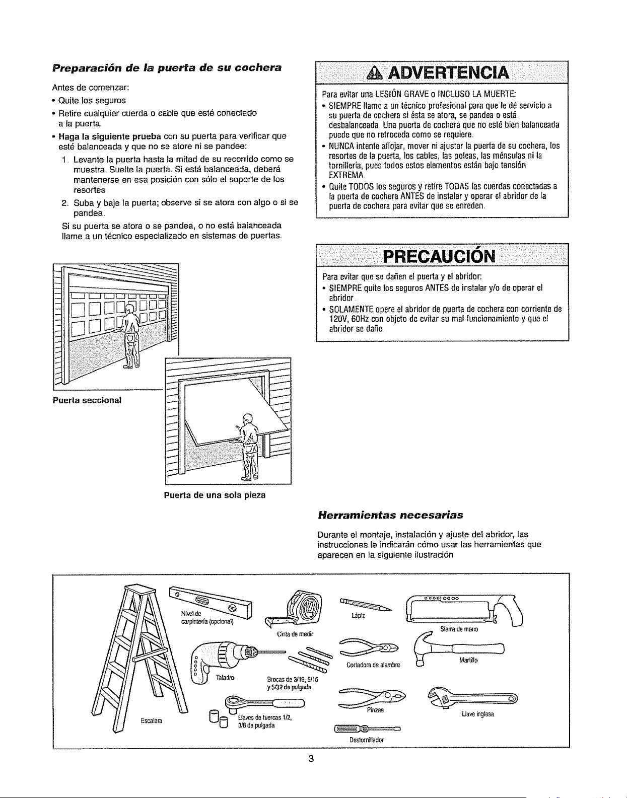
Preparaci6n de la puerta de su cochera
Antes de comenzar:
o Quite los seguros
• Retire cualquier cuerda o cable que est_ conectado
a la puerta
. Haga la siguiente prueba con su puerta para veriflcar que
est,, balanceada y que no se atore ni se pandee:
1, Levante la puerta hasta la mitad de su recorrido come se
muestra. Suelte la puertao Si est,. batanceada, deber_
mantenerse en esa posiciSn con sSlo el soporte de los
resortes,
2o Suba y baje la puerta; observe si se atera con algo o si se
pandea
Si su puerta se atora o se pandea, o no est_ balanceada
liame a un t_cnico especiafizado en sisternas de puertas.
Para evitar unaLESIONGRAVEo INCLUSOLA MUERTE:
• SIEMPREflame a un t_cnico profesienafparaque led_ servicioa
su puertade cocherasi _sta se atora,se pandeao est_
desbalanceadaUnapuerta de cocheraque noest_ bienbalanceada
puedequeno retrocedacome se requiere..
• NUNCAintenteaflojar, mover ni ajustar la puertade su cochera, [os
resortes de la puerta,10scanes, laspoleas, las m_nsulasni la
tornilleria, pues todos estos elementosest_nbajo tensi6n
EXTREMA
- QuiteTODOSlos segurosy retire TODASlascuerdasconectadasa
fa puerta de cocheraANTESdeinstalar y operar el abridor de la
puerta de cocherapara evitar que se enreden
Pue_a seccional
Puerta de una sola pieza
Paraevitar que sc damonet puertay el abridor:
• SIEMPREquite los segurosANTESde instalary/o de operar el
abridor
• SOLAMENTEopere el abridor de puertadecocheracon corrientede
120V,60Hz con objeto de evitar su realfuncionamientey que el
abrid0r se dafie
Herramientas necesarias
Durante et montaje, instalaci6n y ajuste del abridor, ias
instrucciones le indicar&n c6mo usar las herramientas que
aparecen en ]a siguiente ilustraci6n
Sierrademale
Ua_ ingte_
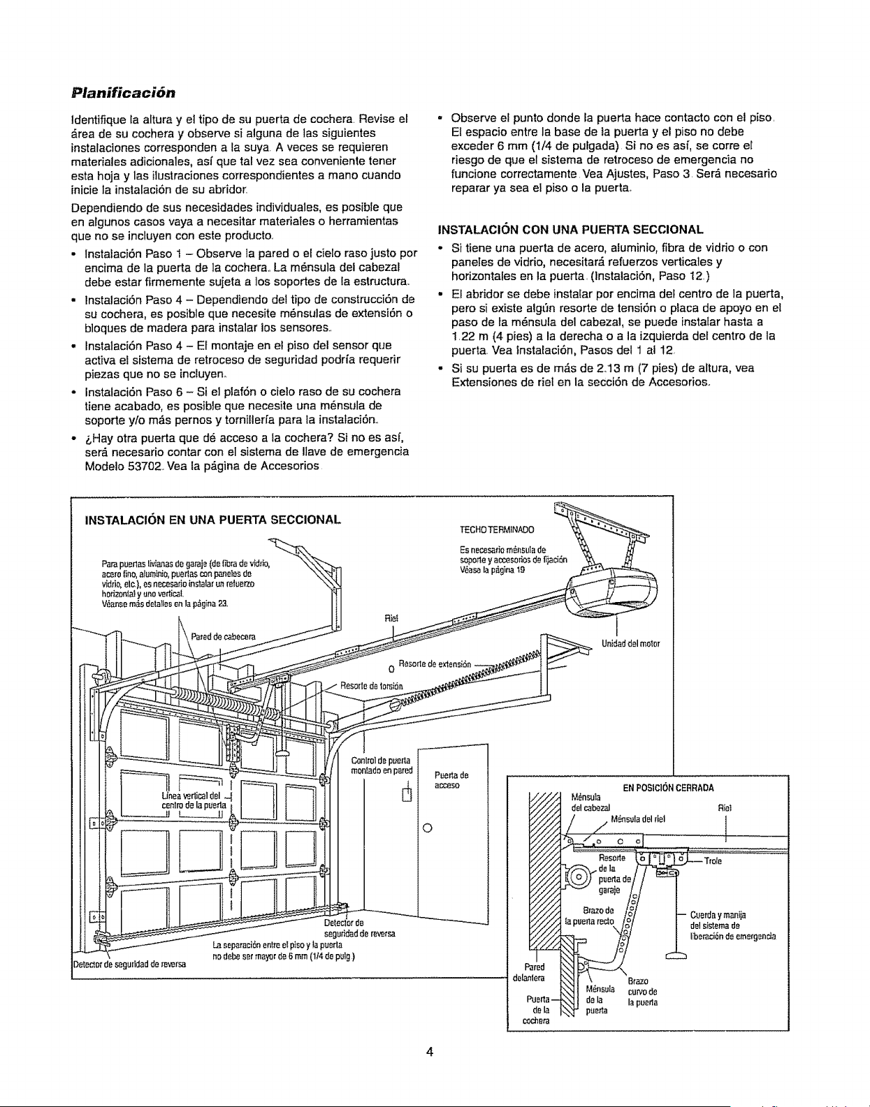
Planificaci6n
Identifique la altura y et tipo de su puerta de cochera Revise el
__reade su cochera y observe si alguna de las siguientes
instalaciones corresponden a la suya A veces se requieren
materiales adicionales, asf que tat vez sea conveniente tener
esta hoja y las ilustracienes correspondientes a mane cuando
inicie la instalaciSn de su abridor.
Dependiendo de sus necesidades individuales, es posibte que
en algunos cases vaya a necesitar materiales o herramientas
que no se inctuyen con este producto_
• lnstalaciSn Paso 1 - Observe la pared o el ciefo raso justo per
encima de la puerta de ]a cochera., La m6nsula det cabezat
debe estar firmemente sujeta a los soportes de ta estructura..
. lnstalaciOn Paso 4 - Dependiendo del tipo de construcciSn de
su cochera, es posible que necesite m6nsulas de extensiSn o
bloques de madera para instalar los sensores.,
• Instalaci6n Paso 4 - El montaje en el piso del sensor qtte
activa el sistema de retroceso de seguddad podrfa requerir
piezas que no se incluyen,
• InstataciSn Paso 6 - Si e] plaf6n o cielo raso de su eochera
tiene aeabado, es posible que necesite una m_nsula de
sopode ylo m#,s pernos y tornillerfa parr la instalaciSn.,
• &Hay otra puerta que d#,acceso a la cochera? Si no es asf,
ser_. necesario contar con el sistema de Ilave de emergencia
Modelo 53702. Vea la pa'gina de Accesorios
Observe el punto donde la puerta hace contacto con el piso
Et espacio entre la base de la puerta y el piso no debe
exceder 6 mm (t/4 de putgada)Si no es asf, se corre el
riesgo de que el sistema de retroceso de emergencia no
funcione correctamente Vea Ajustes, Paso 3 Ser_ necesario
reparar ya sea el piso o la puerta_
INSTALACION CON UNA PUERTA SECCIONAL
• Si tiene una puerta de acero, aluminio, fibra de vidrio o con
panetes de vidrio, necesitar__refuerzos verticales y
horizontales en la puerta. (InstalaciSn, Paso 12.)
. El abridor se debe instalar per encima del centre de la puerta,
pero si existe aig['m resorte de tension o placa de apoyo en el
paso de fa m_nsula del cabezal, se puede instatar hasta a
122 m (4 pies) a la derecha o a la izquierda def centre de la
puerta Vea tnstalaciOn, Pasos del 1 al 12
• Si su puerta es de m_s de 2,.13 m (7 pies) de altura, yea
Extensiones de riel en la secciOn de Accesorios..
INSTALACION EN UNA PUERTA SECCIONAL
Dele_lorde segu(idadde _versa
RiB(
Unidaddel motor
4
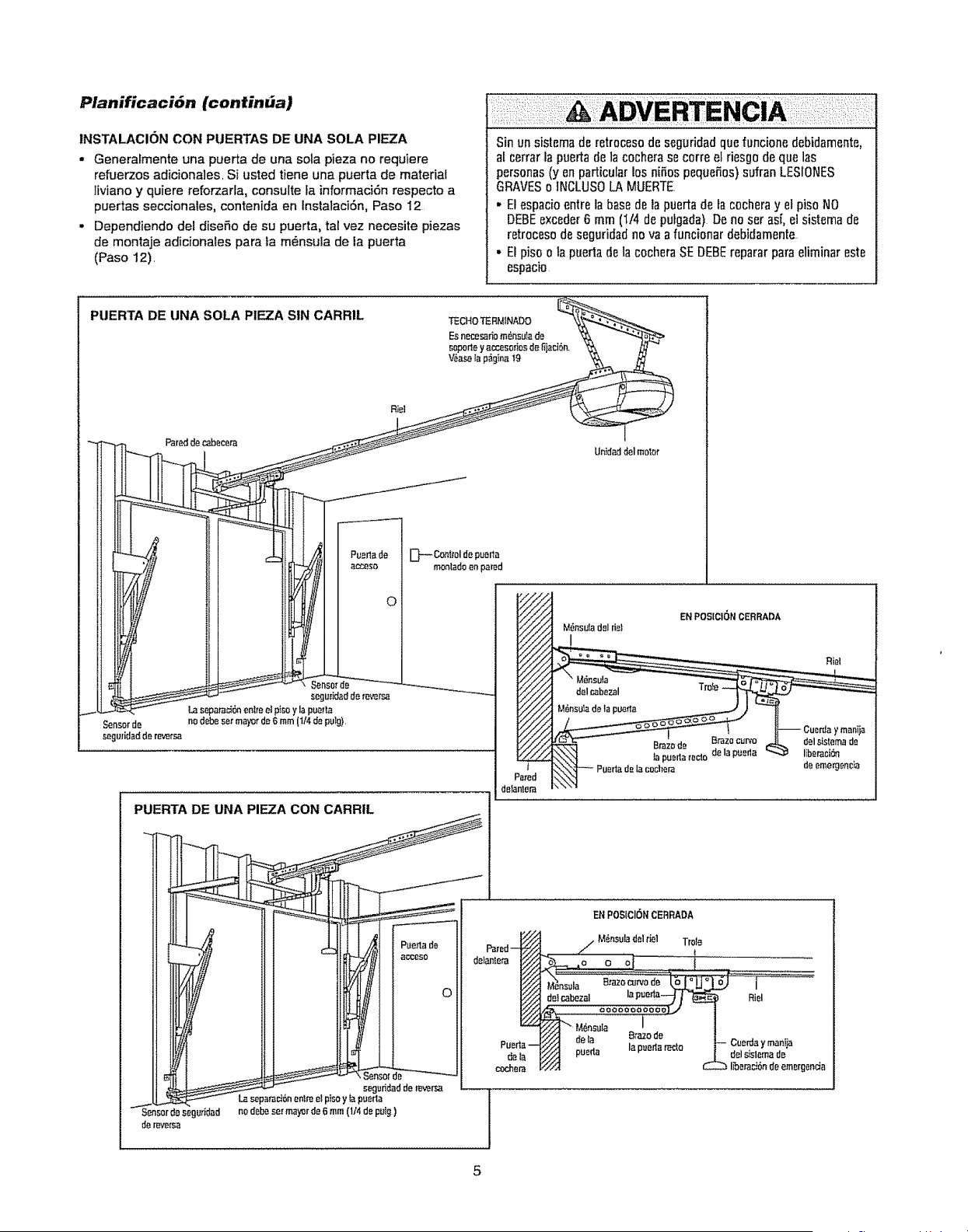
PlanificaciOn (continba)
INSTALACION CON PUERTAS DE UNA SOLA PIEZA
• Generalmente una puerta de una sol° plaza no requiem
refiJerzos adiciona]es, Si usted tiene una puerta de material
liviano y quiere reforzarla, consult° la informaci6n respecto a
puertas seccionales, contenida en instataci6n, Paso I2
• Dependiendo del dis°rio de su puerta, tal vez necesite piezas
de montaje adicionates para la m_nsula de la puerta
(Paso 12),
; ADVERTEINCIA I i: i
Sin un sistemade retrocesodeseguridadquafuncione debidamente,
af cerrarla puertade la cachet° se corre el riesgo de qua las
personas(y an particularlos ni_,ospeque_os)sufran LESIONES
GRAVESo ]NCLUSOLA MUERTE
• Elespacioentre la basede la puerta de lacocheray el pisoNO
DEBEexceder6 mm (t/4 de pulgada)De no set asi, el sistema de
retrocesodo seguridadno va afuncionar debidamente,
• Etpiso o ta puertadola cachet°SE DEBEreparar par° eliminareste
espacio
PUERTA DE UNA SOLA PIEZA SIN CARRIL
Riel
0
seguHdadde re_rsa
La se _ara_6nenlreel picay la pue_a
no debeset mayorde 6 mm(t14depulg),
[:}-_ Controlde puarla
monladoenpared
deta
cachet°
Unidaddelmolar
M6nsu]adel fiel
I
EN POSICI6N CERRADA
de I_mergenr;ia
ENPOSICIONCERRADA
M_nsuladel fiel Trote
Riel
Cuerday manija
del slslemade
beraci6nde emergenda
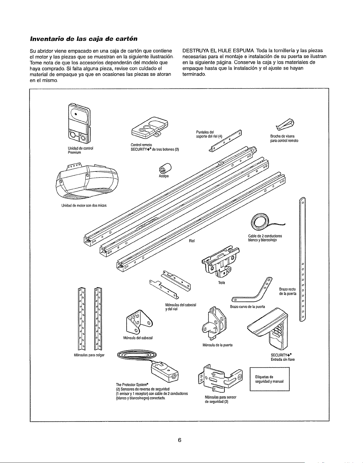
lnventario de las caja de cart6n
Su abfidor viene empacado en una caja de cart6n que contiene
er motor y las piezas que se muestran en la siguiente ilustraci6n
Tome nota de que los accesorios depender,_n del modelo que
haya comprado_ Si falta atguna pieza, revise con cuidado el
material de empaque ya queen ocasiones las piezas se atoran
en e] mismo,
DESTRUYA EL HULE ESPUMA Toda ia tornilleria y fas piezas
necesarias para el montaje e instalaci6n de su puerta se ilustran
en la siguiente p6gina, Conserve la caja y los materiates de
empaque hasta que la instalaci6n y el ajuste se hayan
terminado,
Aco_pe
Riel
M_nsuladelcabezal
M6nsuiasdel cabeza]
y dot flel
ThaProtect0rSystem"
(2}Sens0msde mver_ de seguridad
(! emisory 1 recepto$concablede2 conducta,,es
_olancoybtar_c_tnegro)conedad_
Trola
SECURITY÷"
Enlmdas_nIlave
M,a,nsulasparasensa_
dese(3uridad(2)
Etique_asdB
seguddady manual
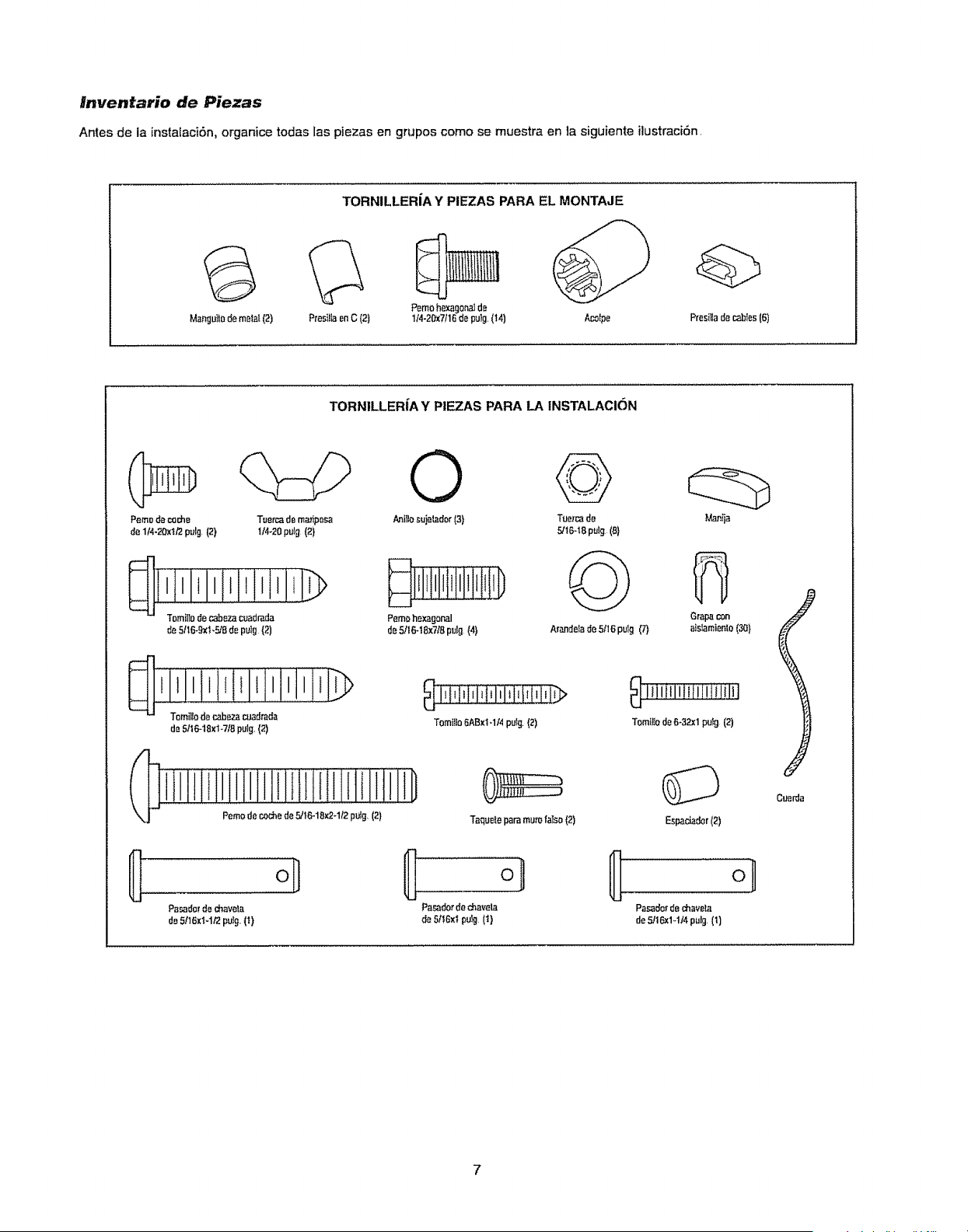
#nventario de Piezas
Antes de la instalaci6n,organicetodas las piezas en grupos como se muestraen la siguiente ilustraci6n,
TORNILLERIA Y PIEZAS PARA EL MONTAJE
Presil]aenC (2)
Pemohexagon_tde
Ma_gu_lodemeta{(2) !/4.20x7116de pu}g(14)
TORNILLERIA Y PIEZAS PARA LA INSTALACION
PresilIader.,ables(6)
Pemo dem_e Tuercade ma/iposa
de I/4.20xI/2pulg,(2} U4-20pulg(2}
__iiii_li _,,, i]_
da 5/16-18xt-7/Bpulg,(2)
© ©
knillo_uj_dor(3) Tue_cad_
5/16-IBpulg(B}
@
Pemo ho_gonal
d_5t16-18x718pulg (41 Arande_ade5/16putg ('7)
Mat_ja
GraNtcon
alstamienlo(30t
T(_mitlodeB-32x1pu_g (2)
Espaciador(2)
PBsado_'de d_avela Pa_dor ded_avela Pasado_de ¢hav_ta
de5116X_-1/'2pUIg(I) de 5,t1_BxtpuIg (t) de 5!16x1,,114pulg,(1)
Cuerda
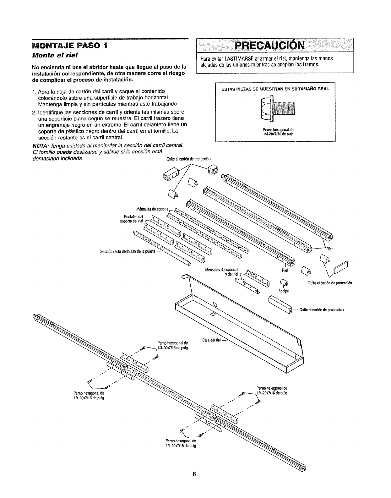
MONTAJE PASO t
Monte el riel
No encienda ni use el abridor hasta que Ilegue al paso de la
instalaci6n correspondiente, de otra manera corre el riesgo
de complicar et proceso de instalaci6no
Paraevitar LASTIMARSEat armar el riel, mantengalas man0s
alejadasde l_s unionesmientras se acoplanlos tramos,
1o Abra la caja de cart6n del carril y saque el contenido
coloc_ndolo sobre una superficie de trabajo horizontal,
Mantenga timpia y sin part{culas mientras est_ trabajando
2, ldentifique las secciones de carril y oriente las mismas sobre
una supe_cie ptana segrbn se muestra, El carril trasero tiene
un engranaje negro en un extremo. El carril delantero tiene un
soporte de pl&stico negro dentro del carrH en el tornillo, La
secci6n restante es el carrH central.
NOTA: Tenga cuidado al manipular la secci6n de/carrif central
El torniflo puede deslizarse y sa/irse si la secci6n est_
demasiado inclinada,, ou_eelcart6nd_pt'oter__6n
ESTAS PIEZAS SE MUESTRAN EN SUTAMAI_O REAL
P_m0hexagonalde
114-2_7116de pulg
1
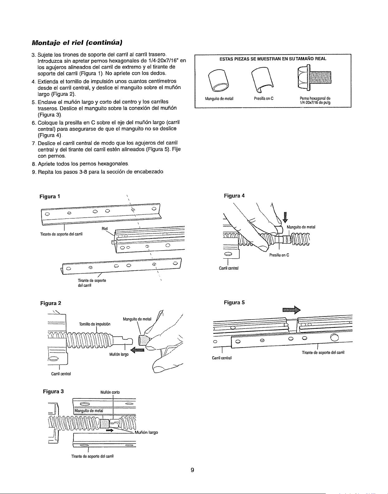
Montaje el riel (continUa)
3., Sujete los tirones de soporte del carril al carril trasero_
Introduzca sin apretar pernos hexagonales de 1/4-20x7/t 6" en
Ios agujeros aiineados det carril de extremo y el tirante de
soporte del carrii (Figura 1)No apriete con los dedos
4, Extienda el tornillo de impulsi6n unos cuantos cent[metros
desde el carril central, y deslice el manguito sobre el mufiSn
largo (Figura 2).,
5, Enclave el mu56n largo y corto del centro y los cardles
traseros.. Deslice et manguito sobre la conexi6n de! mu56n
(Figura 3)
6, Co_oque ta presifla en C sobre et eje del mu_6n largo (carrit
central) para asegurarse de que el manguito no se deslice
(Figura 4),
7 Destice el carril central de modo que los agujeros de] carfil
central y del tirante del carril est_n afineados (Figura 5), Fije
con pernos,,
8, Apriete todos los pernos hexagonates.
9., Repita los pasos 3-8 para la secciOn de encabezado,
ESTAS PIEZAS SE MUESTRAN EN SUTAMA_IO REAL
Manguilodemetal Prasi_ar_nC Pemoh_a£1onald_
t/4-20x7/16depulg
Figura I
Tirantedesoporledelr..anil
Tirantede soporte
delcar_l
Figura 4
Ca,-_lcentral
Figura 2
/
/
Carrilcenlral
Figura 5
11rantede soportedol canil
Canilcentral
Figura 3
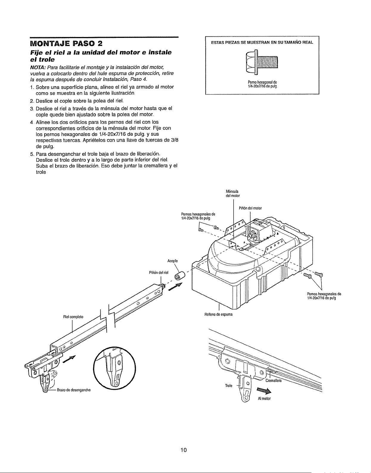
i i i ,w, ,,nluuluululu,n,lt,
MONTAJE PASO 2
Fije el riel a la unidad del motor e instale
el trole
NOTA: Para facilitarle el montaje y la instalaci6n del motor,
vuelva a colocarlo dentro del hule espuma de protecci6n, retire
fa espuma despu6s de concluir Instalaci6n, Paso 4..
1. Sobre una superficie pfana, alinee el riel ya armado al motor
como se muestra en la siguiente ilustraci6n
2, Deslice el copte sobre la polea del rieL
3, Deslice el riel a trav6s de ]a m6nsula del motor basra que el
cople quede bien ajustado sobre la polea de; motor
4 Alinee los dos orificios para los pernos del riel con los
correspondientes orificios de la m6nsula del motor Fije con
los pernos hexagonates de i14-20x7/16 de putg y sus
respectivas tuercas.. Apri6telos con una ilave de tuercas de 3/8
de pulg,,
5. Para desenganchar el trole baja e! brazo de liberaci6n°
Deslice el trole dentro y a lo largo de parte inferior del riel.
Suba el brazo de liberaci6n, Eso debe juntar ]a cremallera y el
trole
ESTAS PIE_AS SE MUESTRAN EN SUTAMANO REAL
Pemohexagonaldo
lt'4_28x?/16deputg
Retleno do espuma
M6nsula
delmotor
Trole
Pemoshexagonalesde
1/4-20x7/16 de puI[I
I0
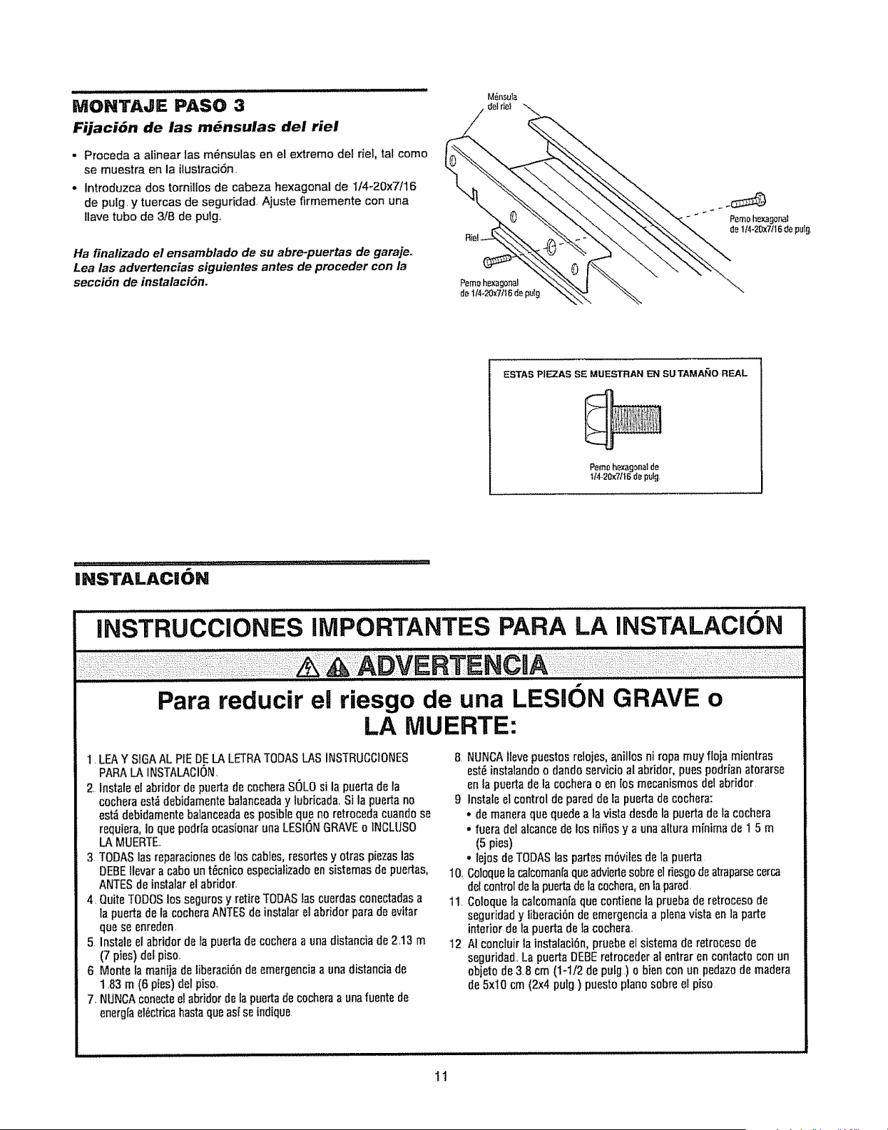
MONTAaE PASO 3
Fijaci6n de las m_nsulas del riel
• Proceda a aEinear1asm_nsulas en el extreme det riel, tal come
se muestra en la ilustraci6n
• Introduzca dos tornit[os de cabeza hexagonal de 1!4+20x7116
de puig, y tuercas de seguridad Ajuste firmemente con una
llave tube de 3/8 de pulg.,
Ha finalizado et ensamblado de su abre-puertas de garaje.,
Lea las advertencias siguientes antes de preceder con la
secci6n de instalaci6n.
M_nsuta
ESTAS P|EZAS SE MUESTRAN EN SUTAMANO REAL
Pemohexagonalde
ti4..20x7/16de pulg,
INSTALACION
ii1,1
INSTRUCCiONES IMPORTANTES PARA LA INSTALAC 6N
Para reducir el riesgo de una LESION GRAVE o
LA MUERTE:
1 LEAY SIGAAL PiE DELA LETRATODASI_ASINSTRUCCIONES
PARALA INSTALACION,
2. Instate e{abridor de puertade cocberaSOLO si la puertade la
cocheraest,'_debidamentebalanceaday lubricada,Si la paerta no
est_debidamentobalanceadaes posibleque no rotrocedacuandose
requiera,io quopodriaocasionaruna LESIONGRAVEo tNGLUSO
LA MUERTE
3 TODASlas reparacionesde los cables,resortesy otras piezaslas
DEBEllevar a caboun t_cnico espociafizadoen sistemasde puertas,
ANTESde instalarel abridor
4, QuiteTODOSlos segurosy retireTODASlascuerdasconectadasa
fa puertade la cocheraANTESdo instaiarel abridor para de evitar
que so enredon,
5 Instaleel abridor de la puoda do cocheraa una distanciade 2,13 m
(7 pies) del piso
6 Monte la manijade iiberaci6nde emergenciaa una distanciade
183 m (6 pies)del piso.,
7. NUNCAconectoel abridorde fa puertade cocheraa unafuentode
enorg[ael_ctricahastaqueas! se indique
8 NUNCAlfevepuestosrelojes, anillos ni ropa muy floja mientras
est_instalandoo dandoservicioaEabridor,pues podrianatorarse
en la puerta dela cocherao en losmecanismosdel abridor
9 Instalo et controldepared de ta puerta de cochora:
• de maneraquequedea la vistadesde la puertade la cochora
. fuera det alcancede DosniSosy a una altura minima do 1 5 m
(5 pies)
• lejos deTODASlas partesm6viles de la puerta
10 Goloquelacalcoman{aqueadviertesobreel riesgodeatraparsecerca
dol controtdelapuertadela cochera,en lapared,
11 Coloqueta calcoman[aquecontienela prueba de retrocesode
seguridady iiberaci6nde emergenciaa plenavista en la parte
interior de lapuerta de lacochera
I2 N concluirla instalaci6n, pruebeel sistema de retrocesode
seguridad,La puertaDEBEretrecederal entrar en contactoconun
objeto de 38 crn(1-1/2 de puLg) o biencon un pedazode madera
de 5xi0 cm (2x4 pulg) puestoplanesobre el piso
11
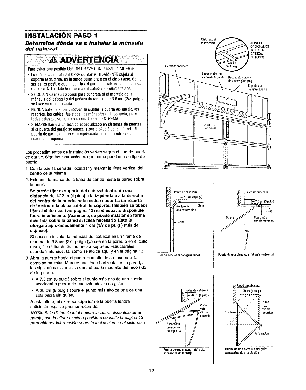
IHSTALACI6N PASO 1
Determine d6nde va a instalar la m_nsula
del cabezal
Paraevitar unaposible LESIONGRAVE0 INCLUSOLA MUERTE:
• La m_nsulade[ cabezalDEBEquedar R[GIDAMENTEsujetaal
soporte estrudrual en la pareddeIanterao en et delo raaso,de no
ser asf es posibleque la puerta del garajeno retrocedacuando se
requiera NO instaleia m{_nsufadel cabezafen muros falsos
• Se DEBENusar sujetaderesparaconcreto si elmontajede la
m_nsuladel cabezalo del pedazodB madBrade 3 Bcm (2x4 pu[g }
se haceen mamposteria
. NUNCAtrate dE aflojar,mover, ni ajustarla puertadel garaje,los
resortes,los cables,tas pleas,Ias m6nsutasni la perneHa,pues
todas estaspiezasestz_nbajo unatensi6n EXTREMA
• SIEMPREtlamea un t_cnico especiaHzadoen sistemas de puertas
si la puertadel garajese atasca,atora o si est_ desquifibrada Una
puertadegarajeque no est_ equifibradapuedeno retroceder
cuandose requiera
Los procedimientos de instalaci6n varfan segt_n el tipo de puerta
de garaje, Siga las instrucciones que corresponden a su tipo de
puerta
1 Con la puerta cerrada, Iocalizar y marcar la Ifnea vertical del
centro de la misma
2 Extender ia marca de la linea de centro hasta Ia pared sobre
la puerta
Se puede fijar el soporte dot cabezal dentro de una
distancia de 1.22 m (4 pies) a ta izquierda o a ta derecha
de! centro de la puerta, solamente si estorba un resorte
de torsiOn o la placa central de soporte.Tambi_n se puede
fijar at cielo raso (ver p_gina 13) si el espacio disponible
fuera insuficienteo (Asimismo, se puede instalar en forma
invertida sobre la pared si fuese necesarioo Esto le
otorgar& aproximadamente ! cm (1!2 de pulgo) m_s de
espacio).
Si necesita instararla m_nsula det cabezal en un tirante de
madera de 3 8 cm (2x4 pulg) (ya sea en la pared o en el cielo
raso), ffje e! tirante firmemente a soportes estructurales
usando tirafondos, tal como se indica aqu( yen la p_,gina 13
3 Abra la puerta hasta el punto mrs alto de su recorrido, tal
come se muestra, Marque una Ifnea horizontal en la pared, a
las siguientes distancias sobre el punto m_s alto del recorrido
de ta puerta:
• A 75 cm (3 pulg) sobre el punto m&s afro de una puerta
seccional o puerta de una sota pieza con gufas
- A 20 cm (8 pu[g ) sobre et punto m_s alto de una de una
sola pieza sin gui'as_
A esta attura, el extremo superior de la puerta tendr_
suficiente espacio para su recorrido
NOTA: Si la distancia total supera la altura disponibte de el
garaje, use la altura mg_ximaposible o consulte ta p_gina 13
para obtener informacidn sobre la instalacidn en el cielo raso
Uneaverticaldel
centr0de tapuerta
Pareddecabecera
---_- 7s m (3pulg)
Punlorfl_s Guta
allo derec_rrido
--Pu_rta
Puerta seccfottal con guia curva
Puerf_de una plezasin riel guia:
acces0rtos de montaje
MONTAJE
OPCIONALDE
MENSULAOE
CABEZAL
ELTECHO
Y
Paredde cabecera
_7,5 cm(3pulg)
Puntam_s
allode reconid0
Puerta _Jeuna piezaconrlel guia horizontal
Pueda de una piezasin fiel gula:
acces0tlosde arliculaci61_
12
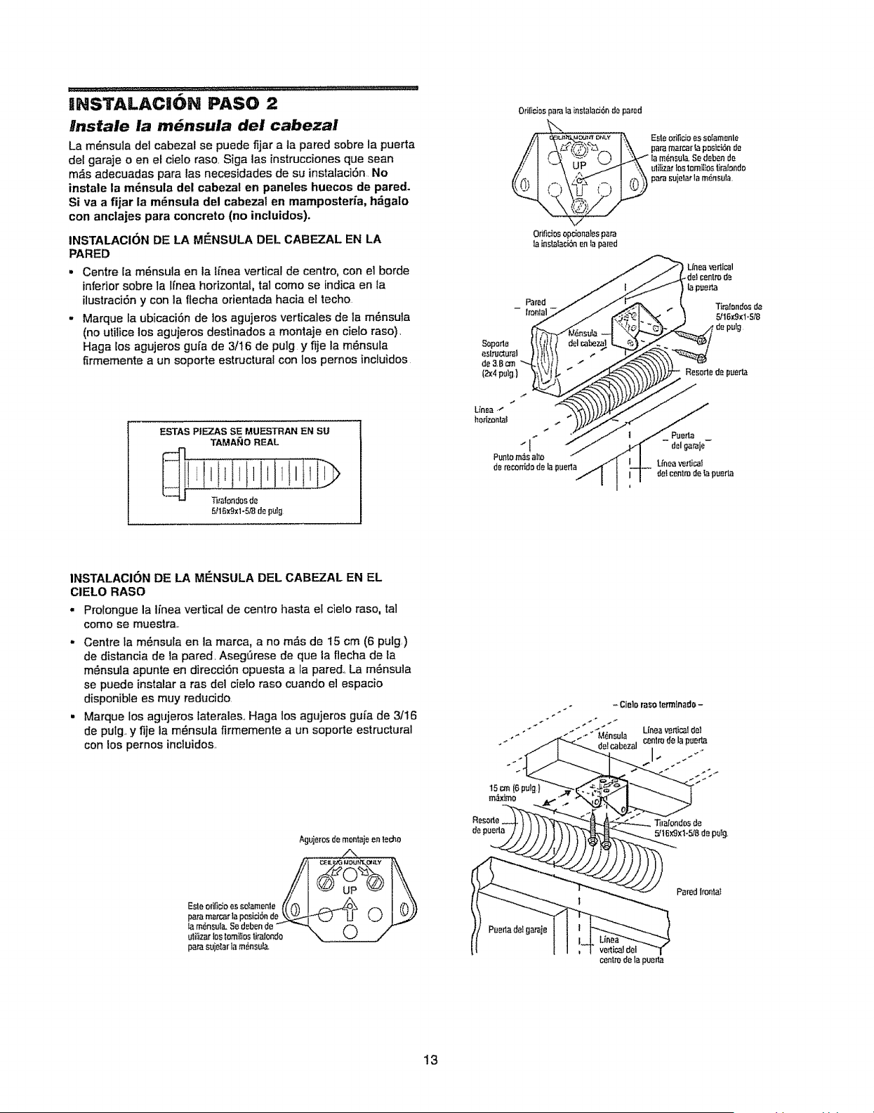
U [ L .................................. , ......... 11 / ,JUt Z ::z:::: ...................................
INSTALAC|ON PASO 2
lnstale la m_nsula del cabezal
La m_nsula de] cabezal se puede fljar a la pared sobre ta puerta
del garaje o en el cieto raso Siga las instrucciones qua sean
m_s adecuadas para las necesidades de su instalaci6n. No
Si va a fijar la mdnsuta del cabezal en mamposteria, h_galo
con anclajes para concrete (no incluidos).
INSTALACION DE LA Mi_NSULA DEL CABEZAL EN LA
PARED
• Centre [a m_nsula en la lfnea vertical de centre, con el borde
inferior sobre ta Hnea horizontal, tal come se indicaen la
ilustraci6ny con la flecha orientada hacia el techo
- Marque [a ubicaci6n de los agujeros verticales de ]a m_nsula
(no utilice los agujeros destinados a montaje an cieto raso).
Haga Eosagujeros guta de 3/16 de pulg y fije la m_nsula
firmemente a un soporte estructurai con los pernos incluidos
ESTAS PIEZ.AS SE MUESTRAN EN SU
TAMAble REAL
...........
5116xgx1-5,_l de pul_l
O_ilicbsp_tala mslalaci6ndepared
/_ . ILIt _._U=OL,_ n D_LY l'_i_ Esle otil_cio es s0tamenle
A_ I_'_xparamamarlapDsici6nde
( _ _= { _ I _lam6nsula. Sedebende
"-"_ UP _ '_ uliliz_rlostomiltostiralondo
\/
Ortf_ciosopcionalespara
lainslalaci_nen la pared
i Unea verl[_l
_del cenlm de
i la pt_ert'-,a
Tiralendos de
5/16K9_I-5,"8
Unea "
herizonlal
"1
Punlom,_s alto
de mcontdo de la puerta
Lfneavertical
del cenlmdelapuerta
INSTALACION DE LA MENSULA DEL CABEZAL EN EL
CIELO RASO
. Prolongue la iinea vertical de centre hasta el cielo raso, tal
come se muestra..
- Centre la m6nsula en ]a marca, a no m_s de t5 cm (6 pulg)
de distancia de la pared. Asegt_rese de qua la flecha de la
m_nsula apunte en direcciOn opuesta a la pared.. La m_nsula
se puede instalar a ras del cielo raso cuando e] espacio
disponible es muy reducido.
. Marque los agujeros faterales,. Haga los agujeros gu_a de 3/16
de putg y fije ta m_.nsula firmemente a un soporte estructural
con los pernos incluidos..
Aguj_rosdemontajeen le_o
/N
patamarcat'laposici6nde ___,,_'1_,,__..) U _....,.)I
la m_nsul_.Sedean de _ _"_ _
utilizarlosIomillostiI'alondo --. k._J /
par__,ujelar tam_nsula
- Clelo t_asoterrnfnadrs-
- ' centrede lapae_
" de!cabezal
15cm (6 pul_)
..,_r
m_ximo
Puertadal gataje
centrode lapuer_
13
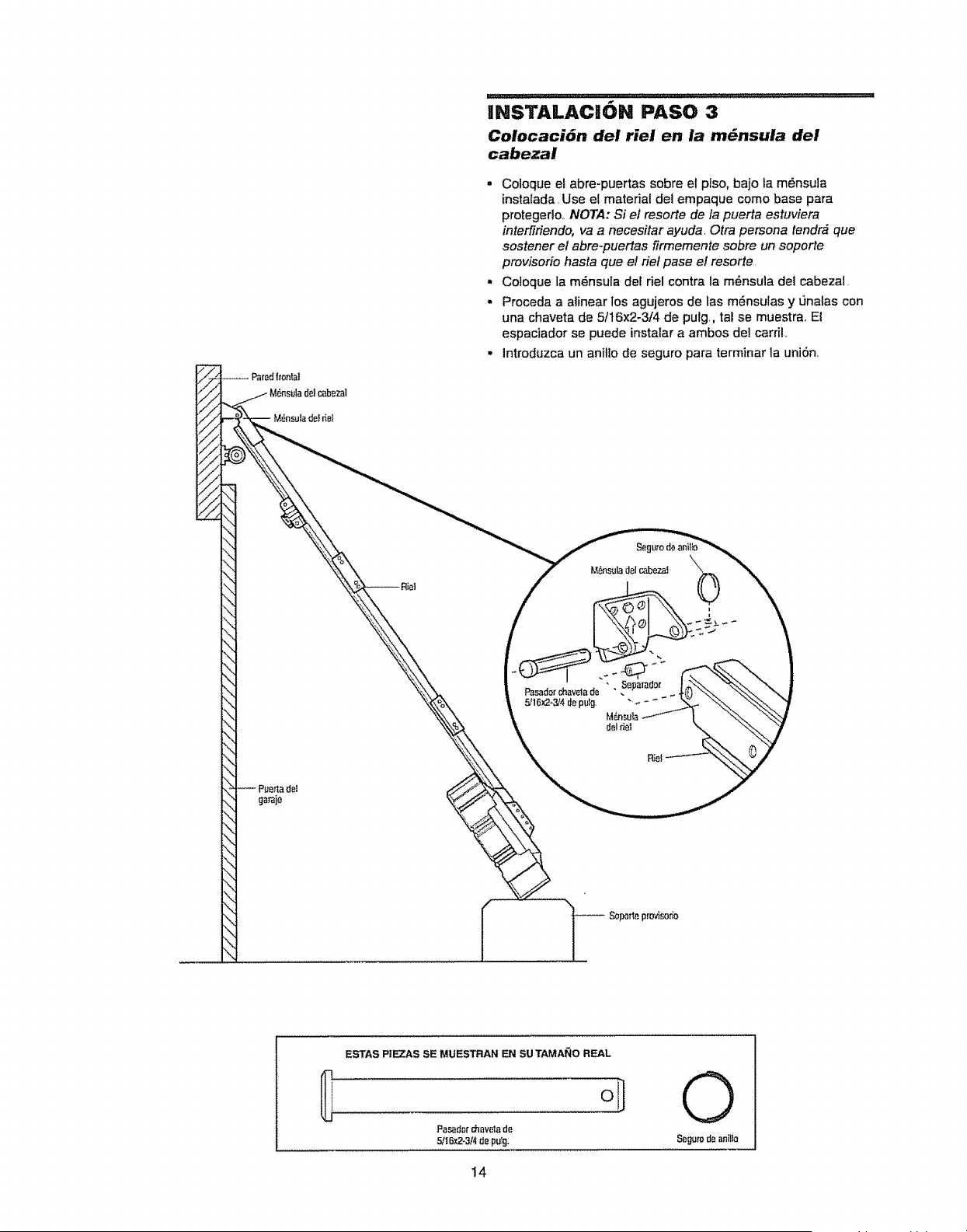
INSTALACI6N PASO 3
Colocaci6n del riel en la m_nsula del
cabezal
. Coioque eLabre-puertas sobre el piso, bajo ta m_nsula
instatada, Use el material del empaque como base para
protegerlo,, NOTA: Si el resorte de la puerta estuviera
interfiriendo, va a necesitar ayuda. Otra persona tendr& que
sostener el abre-puertas firmemente sobre un soporte
provisorio hasta que el riel pase el resorte
- Coloque la m6nsula der del contra la m6nsula del cabezal,
,, Proceda a alinear los agujeros de fas m_nsulas y L_nalascon
una chaveta de 5/16x2-3/4 de pulg,, tal se muestrao El
espaciador se puede instatar a ambos del cardL
. Introduzca un anil]o de seguro para terminar la uni6n,
-- Sopotlaprovisorio
ESTAS PIEZAS SE MUESTRAN EN SU TAMA_O REAL
Pasad_r chavatade
5/16_2-3t4de pulg,
14
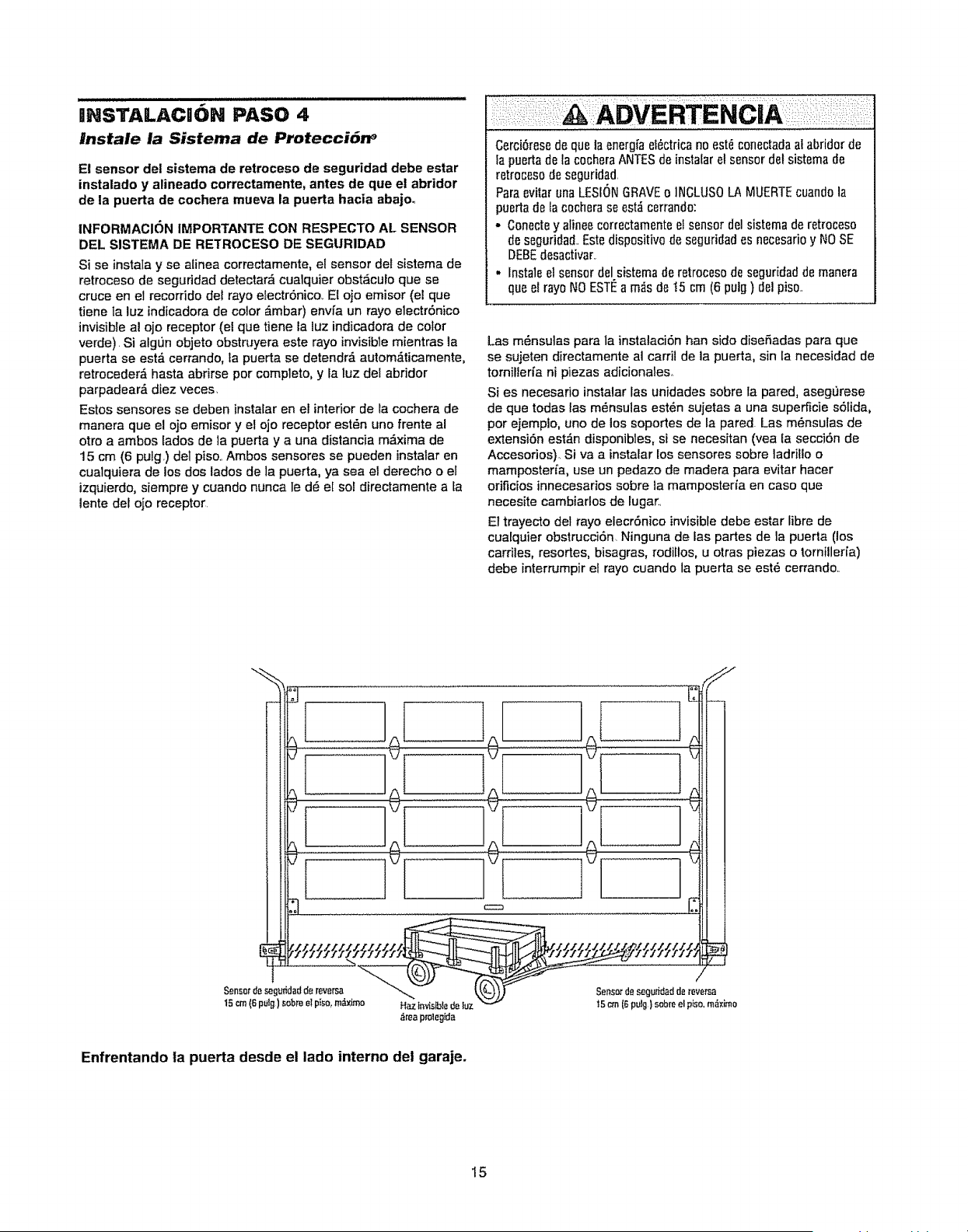
INSTALACK)N PASO 4
#nstale la Sistema de Protecci6n _
E! sensor de! sistema de retroceso de seguridad debe estar
instalado y atineado correctamente, antes de que el abridor
de la puerta de cochera mueva la puerta hacia abajo°
INFORMACION IMPORTANTE CON RESPECTO AL SENSOR
DEL SISTEMA DE RETROCESO DE SEGURIDAD
Si se instata y se alinea correctamente, el sensor del sistema de
retroceso de seguddad detectar_ cualquier obst_culo que se
cruce en el recorrido del rayo electr6nico.. El ojo emisor (el que
tiene ta luz indicadora de color _mbar) envfa un rayo electr6nico
invisible al ojo receptor (el que tiene la luz indicadora de color
verde). Si algL_nobjeto obstruyera este rayo invisible mientras ]a
puerta se est& cerrando, ta puerta ee detendrd autom_ticamente,
retroceder& hasta abrirse per complete, y la luz del abridor
parpadear_, diez veces.
Estoe sensores se deben instaIar en el interior de la cochera de
manera que el ojo emisor y el ojo receptor est_n uno frente al
otro a ambos lades de la puerta y a una distancia m_.xima de
15 cm (6 puig.) deI piso.. Ambos sensores se pueden instalar en
cualquiera de los dos lades de ia puerta, ya sea el derecho o et
izquierdo, siempre y cuando nunca le dR e[ sol directamente a Ia
lente del ojo receptor
Cerci6resode quela energ_aei6ctricano est_conectadaal abridor de
Ia puertadela cocheraANTESde instalarelsensor del sistemade
retr0ces0de seguridad.
Para evitar una LESIONGRAVEo INCLUSOLA MUERTEcuandola
puertade lac0cherase est_ cerrando:
• Conectey alinee correctamenteel sensor del sistemade retroceso
de seguridad.£ste disp0sitivo de seguridad as necesarioy NOSE
DEBEdesactivar.
• Instaleel sensordel sistema de retroces0de seguridadde manera
qua el rayoNO ESTI_a m_sde !5 crn (6 pulg ) del pis0..
Lae m_nsutas pare la instalaci6n han side disefiadas para que
se sujeten directamente al carril de la puerta, sin la necesidad de
tornilleria ni piezas adicionales.
Si es necesafio instalar Ins unidades eobre la pared, asegL_rese
de que todas las m_nsulas est_n sujetas a una supe_cie sOlida,
per ejemplo, uno de los soportes de la pared. Las mOnsutas de
extension est_n disponibles, si se necesitan (vea la secci6n de
Accesorios), Siva a instalar los sensores sobre ladrillo o
mampostefia, use un pedazo de madera para evitar hacer
orificios innecesarios sobre ta mamposteria en case que
necesite cambiarlos de lugar.
El trayecto del rayo elecr6nico invisible debe estar libre de
cuatqu]er obstrucciSn. Ninguna de las partes de la puerta (los
carriles, resortes, bisagras, rodillos, u otras piezas o tornilleria)
debe interrumpir el rayo cuando la puerta se estO cerrando..
Enfrentando ta puerta desde el lado interno dei garaje.
15
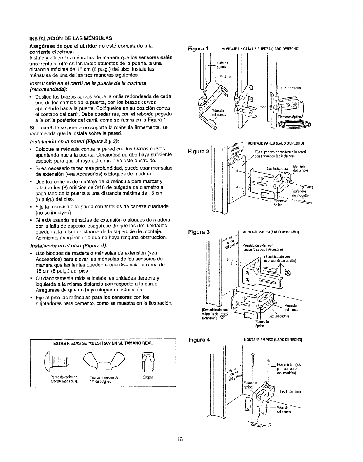
INSTALACION DE LAS MI_NSULAS
Asegurese de que el abridor no est6 conectado a la
corriente el6ctrica.
Instate y alinee las m6nsulas de manera que los sensores est6n
uno frente al otro en los lades opuestos de ia puerta, a una
distancia m_xima de 15 cm (6 putg ) del pisoo Instale las
m6nsulas de una de las tres maneras siguientes:
lnstalaci6n en el carril de la puerta de la cochera
(recomendada):
• Deslice los brazes curves sobre la oritta redondeada de cada
uno de los carriles de la puerta, con los brazes cur¢os
apuntando hacia la puerta.. Col6quelos en su posici6n contra
el costado del carriL Debe quedar ras, con el reborde pegado
a ta orilla posterior dot carril, come se ilustra en la Figura 1..
Si el carril de su puerta no soporta la m6nsula firmemente, se
recomienda que ta instale sobre la pared..
lnstalaciSn en la pared (Figura 2 y 3):
,, Coloque la m6nsula contra la pared con los brazes curves
apuntando hacia la puerta..CerciSrese de que haya suficiente
espacio para que el rayo del sensor no est6 obstruido.
• Si es necesario toner m_s profundidad, puede usar m6nsulas
de extensi6n (yea Accesorios) o bloques de madera..
• Use los orificios de montaje de la m6nsula para marcar y
taladrar los (2) orificios de 3/16 de puigada de di_.metro a
cada lade de la puerta a una distancia m_xima de 15 cm
(6 pulg.) del piso..
• Fije la m6nsula a la pared con tornillos de cabeza cuadrada
(no se inctuyen)
• Si est_ usando m6nsulas de extensi6n o bloques de madera
per la falta de espacio, asegtJrese de que las dos unidades
queden a la misma distancia de la superficie de montaje.
Asimismo, asegL_rese de que no haya ninguna obstrucciOn,
instalaci6n en el piso (Figura 4)"
• Use bioques de madera o m6nsutas de extensi6n (vea
Accesorios) para elevar las m6nsulas de los sensores de
manera que las lentes queden a una distancia m_.xima de
15 cm (6 pulg) del piso.,
• Cuidadosamente mida e instale las unidades derecha y
izquierda a la misma distancia con respecto a la pared
AsegL]rese de que no haya ninguna obstrucci6n.
• Fije al piso [as m6nsulas para los sensores con los
sujetadores para cemento, come se muestra en la iiustraci6n..
ESTAS PIEZAS SE MUESTRAN EN SU TAMANO REAL
Pemodecodmde
t/4-20xH2 depulg,
Tue+camadpesade
1/4depulg*20
Grapas
Figura
MONTAJE DE GU[A DE PUERTA (LADO DERECHO)
Gu_'ado
puerta
"r Peelaiia
_,/_, M6nsub
eo'o'
LUZIndicadora
Figura 2
MONTAJE PARED (LADO DERECHO)
Figura 3
Figura 4
MONTAJE PARED {LADO DERECHO)
Luzindicador_
16
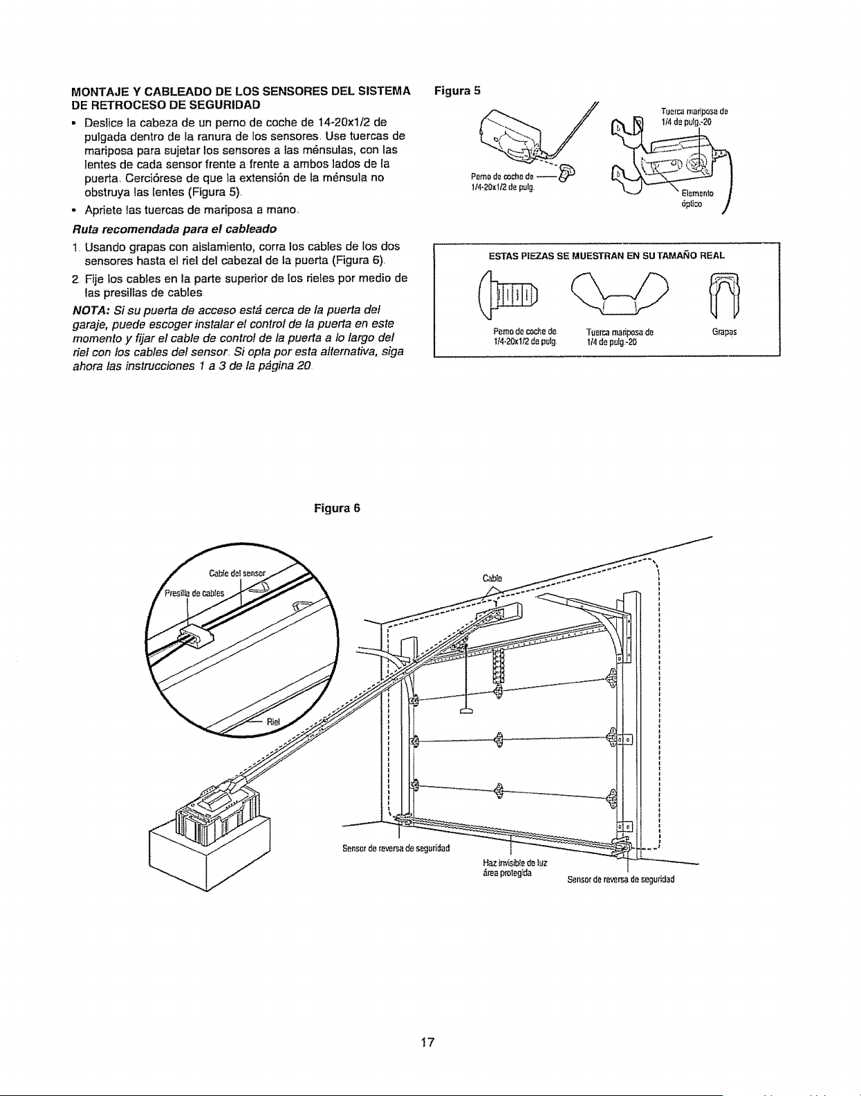
MONTAJE Y CABLEADO DE LOS SENSORES DEL SISTEMA
DE RETROCESO DE SEGURIDAD
• Deslice ta cabeza de un perno de coche de 14-20xl/2 de
pulgada dentro de la ranura de los sensores, Use tuercas de
mariposa para sujetar los sensores a tas m_nsulas, con tas
Ientes de cada sensor frente a frente a ambos ]ados de la
puerta, CerciSrese de que la extensi6n de fa m_nsula no
obstruya las tentes (Figura 5).
,, Apriete las tuercas de madposa a mano,
Ruta recornendada para el cableado
1. Usando grapas con aistamiento, corra los cables de los dos
sensores hasta el riel del cabezal de la puerta (Figura 6),
2 Fije los cables en la parte superior de los deles por medio de
las presiltas de cables
NOTA: Si su puerta de acceso est# cerca de la puerta def
garaje, puede escoger instalar el control de la puerta en este
momento y fijar el cable de control de la puerta a fo largo def
riel con los cables def sensor, Si opta por esta altemativa, siga
ahora /as instrucciones 1 a 3 de la p#gina 20
Figura 5
Figura 6
C.able ÷_"_* I
1
'i
i
!
I I
! !
I
! i
! i
I 1
1 1
_maprolegida
Sensorde reversad_ seguridad
17
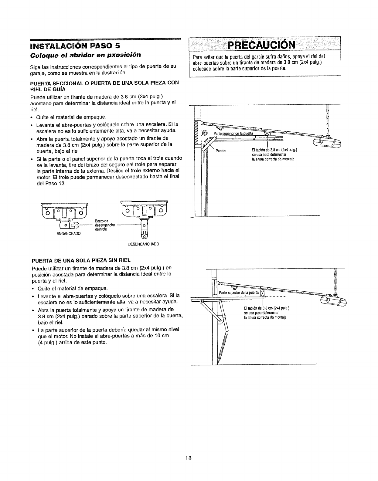
INSTALACION PASO 5
Coloque el abridor en pxosici_n
Siga ias instruccienescorrespendientes af ripe de puerta de su
garaje, come se muestra en ta ilustraci6n,
PUERTA SECCIONAL O PUERTA DE UNA SOLA PIEZA CON
RIEL DE GUiA
Puede utilizer un tirante de madera de 3.8 cm (2x4 pulg)
acostade para determinar la distancia ideal entre la puerta y el
rieL
• Quite el material de empaque
• Levante el abre-puertas y colOquelo sobre una escalera_ Si la
escalera no es Io suficientemente alta, va a necesitar ayuda,
. Abra la puerta totalmente y apoye acostade un tirante de
madera de 3B cm (2x4 pulg.) sebre ta parte superior de la
puerta, baje el riel.
• Si la parle o el panel superior de la puerte toca el trole cuando
se ta levanta, tire del braze del seguro del trole para separar
la parle interne de ia externa,,Deslice el trofe externo hacia el
motor El trole puede permanecer desconectado haste el fnal
del Paso I3.
_ 8tazode
dosenganch_
dellr_le
ENGANCHADO
DESENGANCHADO
Pare evitarque la puerta del garajesufra daF,os, apoye el riefdel
abre-puertassDbreun tirante de maderade 38 cm (2x4 pulg,}
cotocad0sobre la partesuperior de la puerta,
ii
PUERTA DE UNA SOLA PIEZA SIN RIEL
Puede utilizar un tirante de madera de 38 cm (2x4 pulg,) en
posici6n acostada para determinar la distancia ideal entre la
puerta y el rieL
• Quite et material de empaque.
• Levante eI abre-puertas y cel6quelo sobre una escalera, SI la
escatera no es Io suficientemente alta, va a necesitar ayuda.
• Abra la puerta totalmente y apoye un tirante de madera de
38 cm (2x4 pulg.) parade sobre la parte superior de la puerta,
bajo el riel,
• La parle superior de la puerta deberfa quedar al mismo nivel
que el motor., No instale et abre-puertas a m&s de 10 cm
(4 putg) arriba de este punto,
18
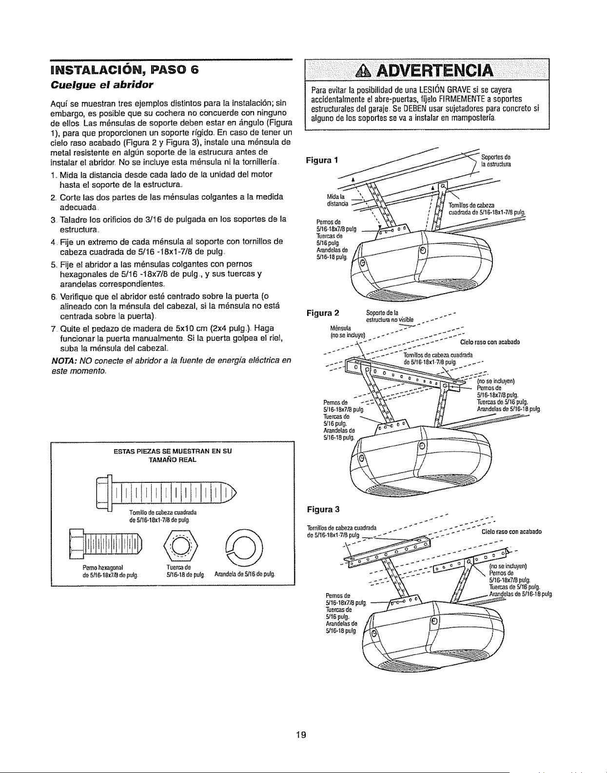
IINSTALACION, PASO 6
Cuelgue el abridor
Aquf se muestran tres ejemplos distintos pare ta instalaci6n; sin
embargo, es posible que su cochera no concuerde con ninguno
de ellos Las m6nsulas de soporte deben estar en #mgulo (Figure
1), para que proporcionen un soporte ri'gido.,En case de tener un
cielo raso acabado (Figure 2 y Figure 3), instal° una m6nsula de
metal resistente en algdn soporte de la estrucura antes de
instafar el abridor, No se incluye esta m6nsula ni la tornillerfa
1,,Mida la distancia desde cada lade de la unidad del motor
haste el soporte de la estructura+
2, Corte las dos partes de las m6nsulas colgantes ala medida
adecuada,
3 Taladre los orificios de 3/16 de pulgada en los soportes de la
estructura,
4L Fije un extreme de cada m6nsuta al soporte con tornillos de
cabeza cuadrada de 5/16 -18xi-7/8 de putg,
5+Fije el abridor alas m6nsulas colgantes con pernos
hexagonales de 5/16 -18x7/8 de pulg., y sus tuercas y
arandelas correspondientes,,
6, Verifique que el abridor est6 centrado sobre la puerta (o
atineado con la m6nsula del cabezal, si fa m6nsula no est&
centrada sobre la puerta).
7 Quite el pedazo de madera de 5x10 cm (2x4 pulg,), Haga
funcionar la puerta manuaimente Si la puerta golpea et riel,
suba la m6nsula del cabezaL
NOTA: NO conecte et abridor a fa fuente de energfa el#ctrica en
este memento.,
ESTAS PIEZAS SE MUESTRAN EN SU
TAMANO REAL
Paraevitar la p0sibilidad de una LESI(_NGRAVEsi se cayera
accidentalmenteel abre-puertas,fijele FIRMEMENTEa soportes
estructuralesd_l garaje.Se DEBENusar sujetadorespara concrete si
algunode los soportesso va a instalar en mamp0steria.
F+...., _...- s+o,o+°e
Mid_
distanda __iltos der.,abe_
f_ ', '_ ,_ _ cuadmdade5/16-18xl-718pul_.
po..o,de / fl'/
5/16.t8x7/8pu_g _ o e ___
TuBrcasde _/ 1\
s/mpulg, p__\
5/16-18pu_g,
J j
19
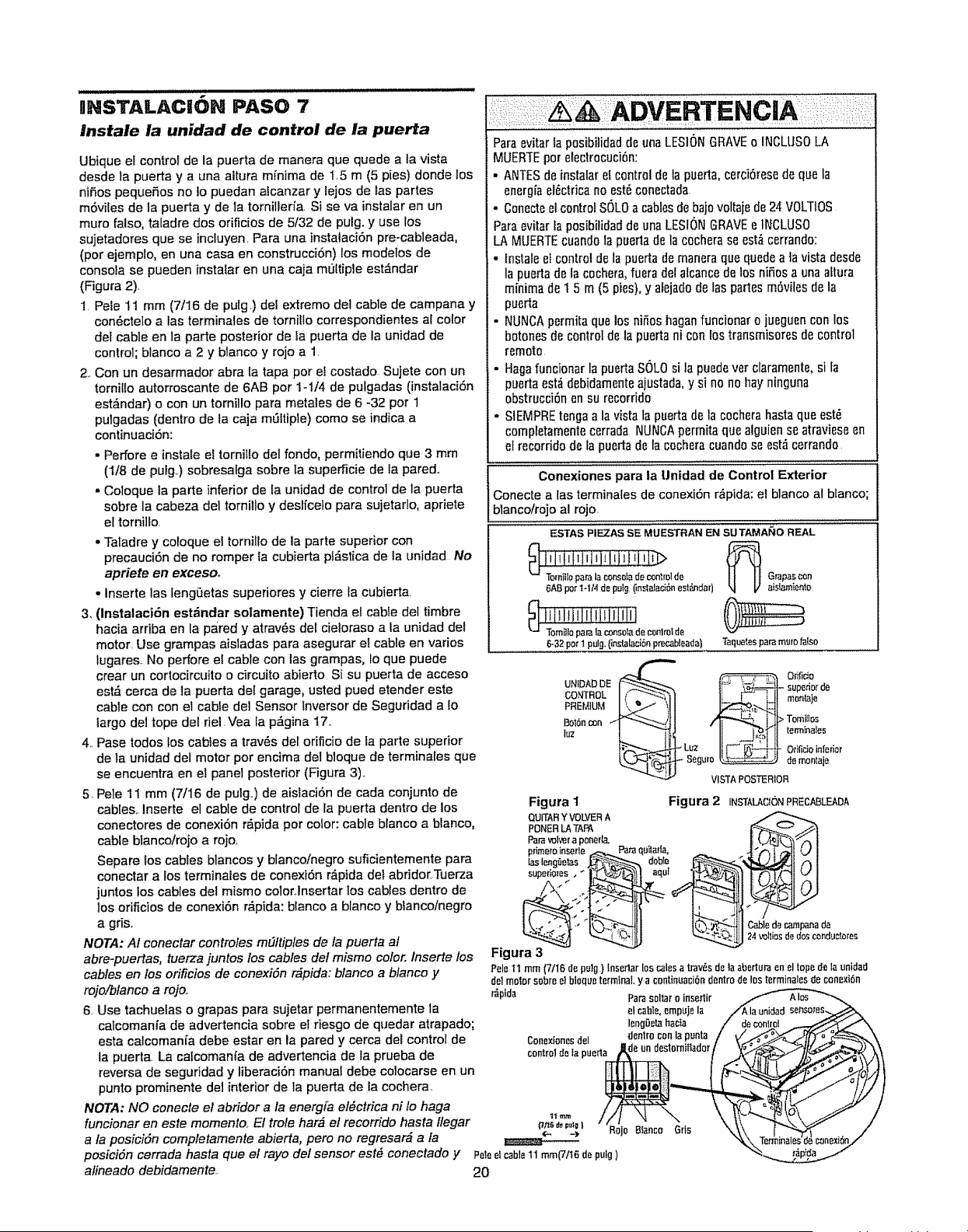
INSTALACi6N PASO 7
Instale la unidad de control de la puerta
Ubique et control de la puerta de manera que quede a la vista
desde la puerta y a una altura mfnima de 1.5 m (5 pies) donde los
nifios pequefios no Io puedan atcanzar y tejos de las partes
m6viles de la puerta y de la torniller_a Sise va instalar en un
mute false, tafadre dos orificios de 5/32 de pulg. y use los
sujetadores que se incluyen. Para una instalaci6n pre-cableada,
(per ejemplo, en una casa en construcci6n) los modelos de
consola se pueden instatar en una caia muttiple est_ndar
(Figura 2).
1 Pele 11 mm (7/16 de pulg.) del extreme del cable de campana y
con6ctelo a tas terminales de torn!lie correspondientes al color
de! cable en la parts posterior de la puerta de la unidad de
control; blanco a 2 y blanco y rojo a 1.
2_ Con un desarmador abra la tapa per e! costado Sujete con un
tornilto autorroscante de 6AB per 1-1/4 de pulgadas (instalaci6n
est_ndar) o con un tornillo para metales de 6 -32 per 1
pulgadas (dentro de la caja mQItiple) come se indica a
continuaci6n:
° Perforee instale el tornillo del fondo, permit!°halO que 3 mm
(1/8 de pulg.) sobresalga sobre ta superficie de la pared..
,,Coloque la part° inferior de fa unidad de control dRla puerta
sobre la cabeza de1tornillo y deslfceto para sujetarlo, apriete
el tornilto
• Taladre y cotoque el tornillo de la parte superior con
precauci6n de no romper la cubierta pl,_sticade la unidad No
apriete en excesoo
- Insert° las lengOetas super!ores y cierre la cubierta
3. (Instalaci6n est,_ndar solamente) Tienda el cabie del timbre
hacia ardba en la pa.red y atrav6s del cieloraso a la unidad det
motor. Use grampas aisladas para asegurar e! cable en varies
tugares.. No perfore el cable con las grampas, Io que puede
crear un cortocircuito o circuito abierto Si su puerta de acceso
est_ cerca de la puerta del garage, usted pued °tender este
cable con con el cable del Sensor lnversor de Seguridad a to
largo del tope det riel.Vea la p_gina 17..
4. Pase redes los cables a trav6s del orificio de la part° superior
de la unidad del motor per encima de! bloque de terminales que
se encuentra en el panel posterior (Figura 3)_.
5 Pele 11 mm (7/16 de pulg..) de aislaci6n de cada conjunto de
cables., inserte el cable de control de la puerta dentro de los
conectores de conexi6n r,_pida per color: cable blanco a blanco,
cable blancoirojo a rojo_
Separe los cables blancos y blanco/negro suficientemente para
conectar a los terminales dR conexi6n Mpida del abridor.Tue_a
juntos los cables del mismo color..Insertar los cables dentro de
los orificios de conexi6n r,_pida: blanco a blanco y blanco/negro
a gr_S,r
NOTA: AI conectar controles m_ftiples de la puerta al
abre-puertas, tuerza juntos los cables del mismo color. Inserte los
cables en los orificios de conexidn r_pida: blanco a blanco y
rojo/blanco a rojo..
6. Use tachuelas o grapas para sujetar permanentemente la
calcomania de advertencia sobre el fiesgo de quedar atrapado;
esta calcoman[a debe estaren la pared y cerca del control de
la puerta La catcomanfa de advertencia de la prueba de
reversa de seguridad y liberaci6n manual debe colocarse enun
punto prominente det interior de la puerta de la cochera
NOTA: NO con°ere el abridor a la energfa el_ctrica ni fo haga
funcionar eneste memento. Et trole hark el recorrido hasta lfegar
a la posiciSn completarnente abierta, pero no regresar_ a la
Paraevitar la posibilidadde unaLESIONGRAVEo INCLUSOLA
MUERTEper etectrocuci6n:
• ANTESde instalare! control deta puerta, cerci6resede que la
energiael6ctricano °st6 conectada
. Conecteel controlSOLOa cablesdebajovottaiede24 VOLTIOS
Paraevitar fa posibiliBadde unaLESIONGRAVEe 1NCLUSO
LA MUERTEcuandola puedade la cocherase est,_cerrando:
- Instal° et control dela puertade maneraque quedea ]a vista desde
la puertade la c0chera,fuera det alcancede los nifi0s a unaaftura
minima de 1 5 m (5 pies),y alejadode las partesm6vilesde la
puerta
• NUNCApermitaquelos nifios haganfuncionar o jueguencon 10s
bot0nesde control de la puertani con los transmisores decontrol
remot0
- Hagafuncionar la puertaSOLOsi la puedevet claramente,si fa
puertaest,_debidamenteajustada,y si no no hay ninguna
obstrucci6n ensu rec0rfido
° SIEMPREtenga a la vista ta puerta de la cochera hastaqua °st6
completamentecerrada NUNCApermitaque alguien se atravieseen
et recorrWo de la puertadela cocheracuandose est_ cerrando
Conexiones para la Unidad de Control Exterior
Conecte alas terminates de conexi6n r_pida: el blanco al bfanco;
blanco/rojo al rojo.
ESTAS PIIEZAS SE MUESTRAN EN SU TAMAle,tO REAL
6ABper t-1/4 depWg(instalaci6nest_ntfar)
e c0nlrol de
6-32I_r 1pulg.(instalaciSnprecabteada}
_ Grapascon
aislamienio
Taquetesparamumfalso
UNIDADDE _IJ _I- supedorde
cONTROL _tt._ I mot_lajePREMIUM
IJ_ Tomi_l_s
II II'°"'°°'°'
-Luz lii- _I = OtiIicioin[edor
- Segaro_ de monlaje
VISTAPOSTERIOR
Figura I Figura 2 INSTALACI6NPRECABLEADA
posici6n cerrada hasta qua el rayo del sensor est_ conectado y Peleelcablell mm(7116depulg)
alineado debidamente. 20
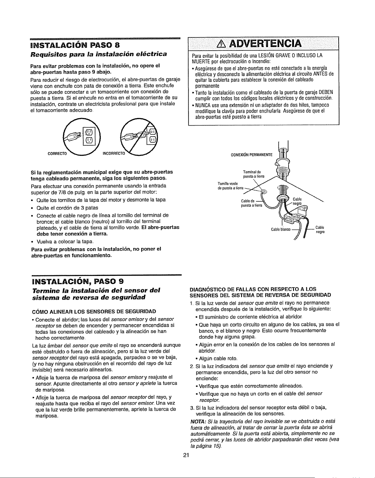
IIHSTALACIION PASO 8
Requisitos para la instalaci6n el_ctrica
Para evitar problemas con la instalaci6n, no opere el
abre-puertas hasta paso 9 abajo.
Para reducir el riesgo de electrocuci6n, e[ abre-puertas de garaje
viene con enchufe con pata de conexiSn a tierra, Este enchufe
sSlo se puede conectar a un tomacordente con conexi6n de
puesta a tierra, Si el enhcufe no entra en el tomacorriente de su
instataciSn, contrate un electricista profesional para que instale
el tomacordente adecuado.
CORREC_
Para evitar la posibilidadde unaLESIONGRAVE0 1NCLUS0LA
MUERTEpor etectrocuci6no incendio:
- Aseg[_resede que el abre-puertasno est6conectado a laenergia
e16ctricay desconectela afirnentaci6nel6ctrica al circuito ANTESde
quitar fa cubiertaparaestablecerla conexi6ndel cabieado
permanente
• Tantola instalaci6ncomo el cableadode la puerta de garajeDEBEN
cumplir cont0dos 10sc6digos locales el6etricosy dec0nstrucci6n..
- NUNCAuse unaextensi6nni un adaptadorde dos hilos, tampoc0
m0difique la clavijaparapoder enchufarta Aseg_resede que el
abre-puertasest6 puesto a tierra
CONEXR)N PERMANENTE
Si la reglamentaci6n municipal exige que su abre-puertas
tenga cableado permanente, siga los siguientes pasos,,
Para efectuar una conexiSn permanente usando la entrada
superior de 7/8 de pulg en la parte superior del motor:
• Quite tos tornillosde ta tapa del motor y desmonte la tapa
, Quite el cord6n de 3 patas
o Conecte el cable negro de lfnea al tornillo de! terminal de
bronce; el cable blanco (neutro) al tornillo del terminal
plateado, y eJ cable de tierra al tornilto verde. El abre-puertas
debe tener conexi6n a tierra.
. Vuelva a coiocar la tapa,
Para evitar problemas con la instalaci6n, no porter el
abre-puertas en funcionamiento.
Tomilloverde
INSTALACII6N, PASO 9
Termine la instalaci6n del sensor del
sistema de reversa de seguridad
COMO ALINEAR LOS SENSORES DE SEGURIDAD
• Conecte elabridor; las luces delsensor emisory del sensor
receptor se deben de encender y permanecer encendidas si
todas las conexiones del cabteado y la alineaci6n se hart
hecho correctamente,
La luz _mbar del sensor que emite el rayo se encender;_ aunque
est6 obstruido o fuera de alineaciSn, pero si ta Iuz verde del
sensor receptor del rayo est_ apagada, parpadea o se ve baja,
(y no hay ninguna obstrucci6n en e! recorddo del rayo de tuz
invisible) ser_ necesario alinearloso
- Afloje la tuerca de mariposa det sensor emisory reajuste el
sensor, Apunte directamente ai otto sensory apriete la tuerca
de mariposa,
• Afloje la tuerca de mariposa del sensor receptor det rayo, y
reajuste hasta que reciba el rayo del sensor emisor, Una vez
que la luz verde brilte permanentemente, apriete la tuerca de
mariposa,,
21
DIAGNOSTICO DE FALLAS CON RESPECTO A LOS
SENSORES DEL SISTEMA DE REVERSA DE Si=GURIDAD
1, Si {a tuz verde del sensor que emite el rayo no permanece
encendida despu6s de la instalaci6n, verifique io siguiente:
- Et suministro de corriente el6ctrica al abridor.
• Que haya un corto circuito en atguno de [oscables, ya sea el
banco, o et blanco y negro. Esto ocurre frecuentemente
donde hay alguna grapao
, Algun error en la conexiSn de los cables de los sensores al
abridor,
2_
- Algt_n cable roto,
Si la luz indicadora del sensor que emite el rayo enciende y
permanece encendida, pero la luz del otto sensor no
enciende:
• Verifique que est6n correctamente alineados,,
• Verifique que no haya un corto en el cable del sensor
receptor,
3o Si la tuz indicadoradel sensor receptor esta d6bil o baja,
vedfique la alineaciSn de los sensores,,
NOTA: Si la trayectoria del rayo invisible se ve obstruida o est_
fuera de alineaciSn, at tratar de eerrar la puerta _sta se abrir_
autom_ticamente, Si la puerta est_ abierta, simplemente no se
podr_ cerrar, y las luces de abridor parpadear_n diez veces (yea
la p_gina 15),
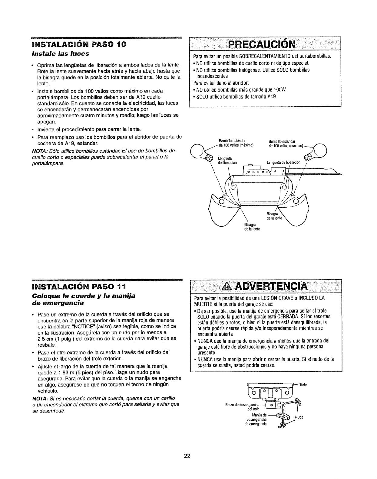
HNSTALACH6N PASO '10
lnstale las luces
• Optima las fengi3etas de liberaci6n a ambos fades de la |ente
Rote la lente suavemente hacia atr_s y hacia abajo hasta que
la bisagra quede en la posici6n tolalmente abierta No quite ta
lente_
. Instale bombillos de 100 varies come m_ximo en cada
portal&mpara. Los bombil!os deben ser de A19 cuetlo
standard s6lo En cuanto se conecte la electficidad, las luces
se encender_n y permanecer_n encendidas per
aproximadamente cuatro minutes y medio; tuego las tuces se
apagan_
° invierta el procedimiento para cerrar la lente.
• Para reemplazo use los bombilIos para el abridor de puerta de
cochera de A19, estandar
NOTA: $6to utifice bombiffos est_ndar. El use de bombiffos de
cuello corto o especiales puede sobrecalentar el panel o la
portal_mpara,
Paraevitar un posibleSOBRECALENTAMtENTOdel portabombillas:
, NOutilice bombillas de cuetlo cortoni detipo especial
. NOutilice bombillas hal6genas UtificeSOLObombillas
incandescentes
Paraevitar daSoal abriclor:
. NOutilice bombillas m_s grande quetOOW
- SOLOutilice bombillas de tamafioAt9
Bombiiloesl_ndar Bombilloesl_dar
_de 100valios(m_.x_mo) de 100valios(m_ximo).._._
\
UNSTALACHON PASO t 1
Coloque la cuerda y ia manija
de emergencia
• Pase un extreme de la cuerda a tray, s del orificio que se
encuentra en la parte superior de la manija roja de manera
que la palabra "NOTICE" (aviso) sea legible, come se indica
en la ilustraciOnr Asegtirela con un nude per lo menos a
25 cm (I pulg.) del extreme de la cuerda para evitar que se
resbale,
. Pase el otro extreme de ia cuerda a trav_s del ofificio del
braze de liberaciOn del trole exterior
. Ajuste el largo de ta cuerda de tat manera que la manija
quede a 1 83 m (6 pies) del piso.,Haga un nude para
asegurarla. Para evitar que la cuerda o la manija se enganche
en algo, asegt_rese de que no toquen el techo de ningSn
vehiculo,
NOTA: Si es necesario cortar la cuerda, queme con un cerilfo
o un encendedor el extreme que cortd para selfarfa y evitar que
se desenrede,
Paraevitar la pesibilidad de una LESIONGRAVEo INCLUSOLA
MUERTEsi la puertadelgarajese cae:
oDeset posible,use la manijade emergenciapara soltar el trole
SOLOcuandola puerta detgaraieest{}CERRADASi los resortes
est_nd_biles o rotes, o bien si la puertaest_idesequilibrada,la
puertapodria caerser_piclay/o inesperadamentemientras se
encuentraabierta
• NUNCAuse la manija de emergenciaa men0s que fa entradadel
garajeest_ libre de obstruccionesy no hayaninguna persona
presente,
° NUNCAuse la manija paraabdr o cerrar lapuerta,,Si el nude de la
cuerdase suefta,ustedpodria caerse
Tmle
Brazededesenga_ch_-_4 o _I_ "_-"
del l_'ole "_'_I I
Man,:!__,d.e_ Nudo
desengan_.e _ ....
de ernerg_cia
22
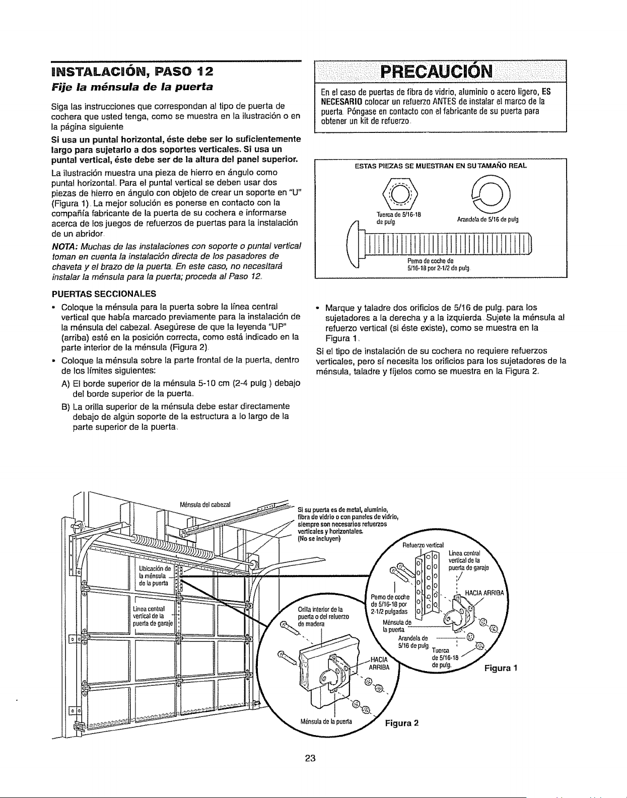
INSTAILACII6N, PASO t 2
Fije la m_nsula de la puerta
Siga los instrucciones que correspondan al tipo de puerto de
cochera que usted tenga, come se muestra en la i[ustraci6n o en
la p_gina siguiente
Si usa un puntat horizontal, _ste debe set Io suficientemente
largo para sujetarlo a dos soportes verticales. Si usa un
puntal vertical, dste debe set de la altura del panel superior.
La ]lustraci6nmuestra una pieza de hierro en _ngulo come
puntal horizontal., Para el puntal vertical se deben usar dos
piezas de hierro en _,ngulo con objeto de crear un soporte en "U"
(F'igura 1). La meier soluci6n es ponerse en contacto con la
compafiia fabricante de la puerto de su cochera e informarse
acerca de }os juegos de refuerzos de puertas para ta instalaci6n
de un abridor.
NOTA: Muchas de !as instalaciones con soporte o puntal vertical
roman en cuenta la instalacidn directa de los pasadores de
chaveta y el braze de fa puerto, En este case, no necesitar_
instalar la m6nsula para fa puerta; proceda al Paso 12,,
PUERTAS SECCIONALES
- Coloque ]a m6nsula para la puerta sobre la tfnea central
vertical que habfa marcado previamente para ta instataciSn de
la m_nsuta del cabezaL AsegL_rese de que la leyenda "UP"
(arriba) est,, en la posici6n correcta, come est,'_indicado en la
parte interior de la m_nsula (Figura 2).
. Coloque la m_nsula sobre la parte frontal de la puerta, dentro
de los lfmites siguientes:
A) El borde superior de la m6nsula 5-10 cm (2-4 putg ) debajo
det borde superior de fa puerta,,
B) La orilla supedor de la m_nsula debe estar directamente
debajo de algL_nsoporte de la estructura a to largo de la
parte superior de la puerto
En el cos0de puertasde libra devidfio,aluminio o acero figero,ES
I'IECESABIOcolocar un refuerzoANTESde instalar el marco de la
puerto PSngaseen centactocon elfabricantede su puerta para
ebtener un kit de refuerz0.
ESTAS P|E2_S SE MUESTRAN EN SUTAMANO REAL
de pulg Arandelade 5/16de pulg
Pemedecochede
5/16.18per2-1/2de pulg
• Marque y tatadre dos orificios de 5/16 de pulg_ parafos
sujetadores a la derecha y a la izquierda, Sujete la m6nsula al
refuerzo vertical (si _ste existe), come se muestra en la
Figura 1,
Si el tipo de instalaci6n de su cochera no requiere refuerzos
verticales, pero si necesita los orificios para los sujetadores de la
m_nsula, taladre y ffjelos come se muestra en la Figura 2.,
M_nselade lapueda Figura 2
LJneacenlral
verticaldela
puertadegaraj_
:/
HACIAABR)B_
Figura 1
23
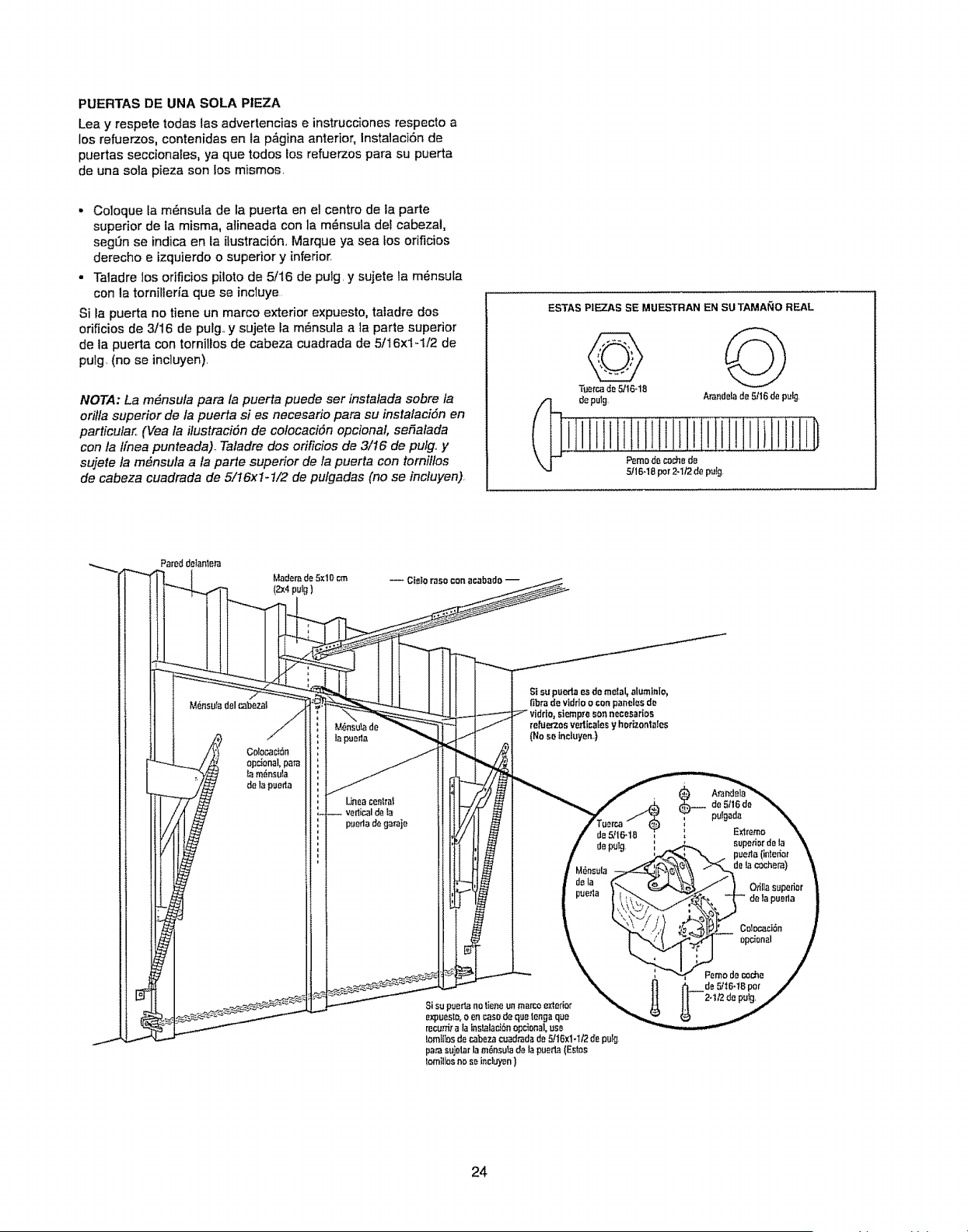
PUERTAS DE UNA SOLA PIEZA
Lea y respete todas las advertencias e instruccionesrespecto a
los refuerzos, contenidas en ta p_gina anterior, InstalaciSn de
puertas seccionales, ya que todos los refuerzos para su puerta
de una so]a pieza son los mismos.
• Co]oque ta m_nsula de la puerta en el centre de la parte
superior de la misma, a]ineada con ]a m_nsu_a del cabezal,
segL'inse indica en la ilustraciSn., Marque ya sea los ofificios
derecho e izquierdo o superior y inferior,
• Taladre los orificios pilate de 5/16 de pulg, y sujete la m_nsu[a
con la tornilleria que se incluye
Si la puerta no tiene un marco exterior expuesto, taladre dos
ofificios de 3/16 de pulg, y sujete ta m_nsu]a ala parte superior
de la puerta con torni]los de cabeza cuadrada de 5/I6x1-1/2 de
pulg, (no se incluyen),
NOTA: La m#nsula pare ta puerta puede ser instatada sabre fa
orilta superior de ta puerta si es necesario pare su instalaciSn en
particular, (Vea la ilustracidn de colocacidn opcional, seSalada
con la t[nea punteada). Taladre dos orificios de 3/16 de pulg, y
sujete la m6nsula ala parte superior de la puerta con total/los
de cabeza cuadrada de 5/16x1-1/2 de pulgadas (no se incluyen)
ESTAS PIEZAS SE MUESTRAN EN SUTAMANO REAL
Tuercade 5/16-18
depufg Arandelade 5/16de pulg,
Pemode roche de
5/16-18par 2-1/2de putg,
Mademde 5xIOcm
(2x4puig)
-- Cie_o raso con aeabado --
M6nsutadelcabezaf
S| supuefla esde me[a[,aluminio,
fibrede vlddo oconpanelesde
p_'esonnocesarioe
reruerzosvedica_esy horizontales
(No sefncluyen,,)
Orilla supariar
de la pueda
24
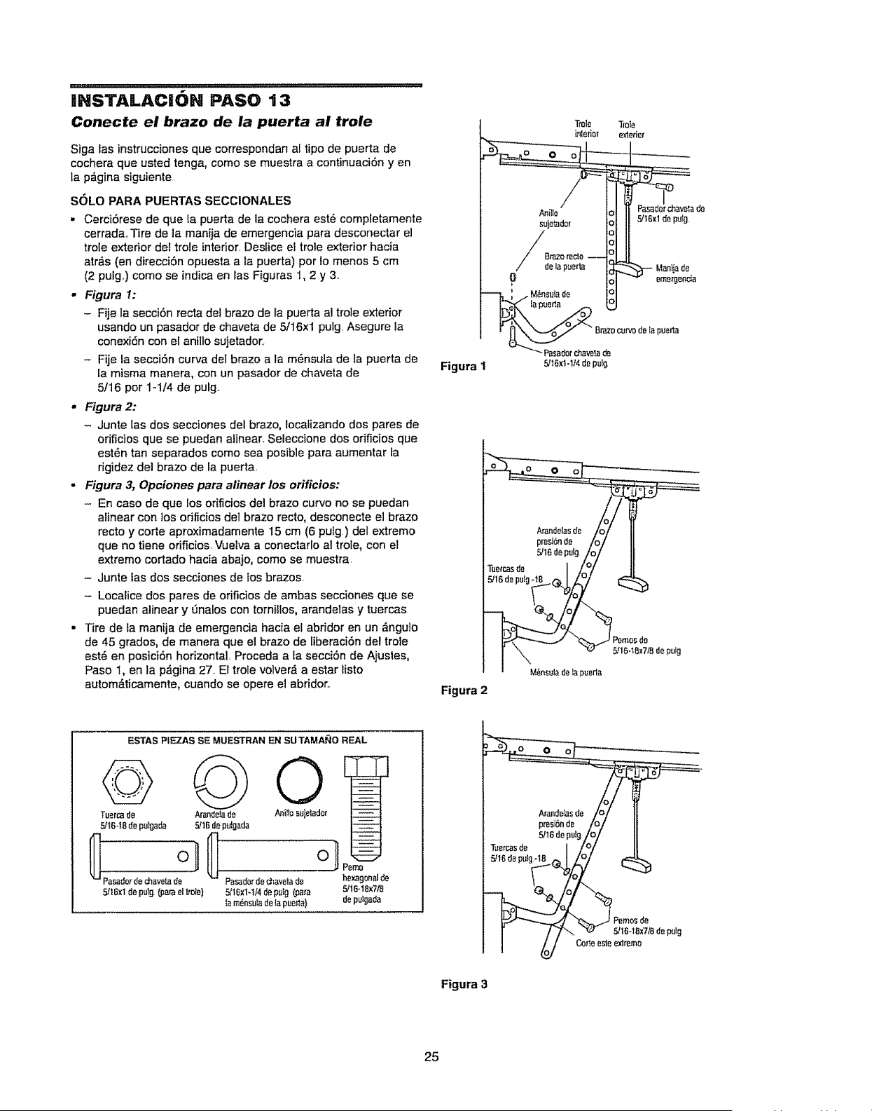
.................................................... :_ .......... ____ IL L I II II IILLL ...... Ul_l ii_ II_LL_II_#L LII g Illl LUL _ L I I P J
INSTALACION PASO 13
Conecte el brazo de la puerta ai trole
Siga las instrucciones que correspondan af ripe de puerta de
cochera que usted tenga, come se muestra a continuaciSn y en
la p&gina siguiente
SOLO PARA PUERTAS SECCIONALES
• CerciOrese de que la puerta de la cochera est_ completamente
cerrada,,Tire de ]a manija de emergencia para desconectar e]
trole exterior del trole interior, Desfice el trole exterior hacia
atrb,s (en direcciOn opuesta a ta puerta) per Io menos 5 cm
(2 pulg,,) come se indica en fas Figuras 1, 2 y 3,
• Figura 1:
- Fije Ia secci6n recta del braze de la puerta al trole exterior
usando un pasador de chaveta de 5/16xl pulg. Asegure la
conexi6n con el anilfo sujetador,
- Fije la secci6n curva del braze a la m_nsula de fa puerta de
la misma manera, con un pasador de chaveta de
5/16 per I-1!4 de pulg,
• Figura 2:
- Junte las dos secciones del braze, Iocafizando dos pares de
orificios que se puedan alinear, Seleccione dos orificios que
°stUn tan separados come sea posible para aumentar la
rigidez del braze de la puerta.,
, Figura 3, Opciones para alinear los orificios:
- En case de que fos orificios del braze curve no se puedan
a[inear con los orificiosdel braze recto, desconecte e] braze
recto y corte aproxirnadamente 15 cm (6 pUlgr)del extreme
que no tiene orificios,Vueiva a conectarlo ai trot°, con el
extreme cortado hacia abajo, come se muestra.
- Junte ias dos secciones de los brazes
- Localice dos pares de orificios de ambas secciones que se
puedan alinear y 0nafos con tornilfos, arande]as y tuercas
Tire de la rnanija de emergencia hacia et abridor en un _ngulo
de 45 grades, de manera que el braze de liberaciOn del tro]e
est_ en posici6n horizontal,. Proceda a fa secciOn de Ajusles,
Paso I, en la p_gina 27. El trote volver_ a °star listo
autom&ticamente, cuando se opere el abridor,
Figura 1
Figura 2
Brae curvedet_ puer_a
Pasad0rchevelade
5/16x1-1/4depuig,
ESTAS PIEZAS SE MUESTRAN F..NSUTAMANO REAL
Pasa_orae_vela de PasarJorde _avetade hexagonal_Je
5H6xl deputg.(parael t_le) 5/16x1-I/4de polg (para 5/16-18x7/8
to m_-nsulade Iopuerla) de pul,;Jada
Figura 3
25
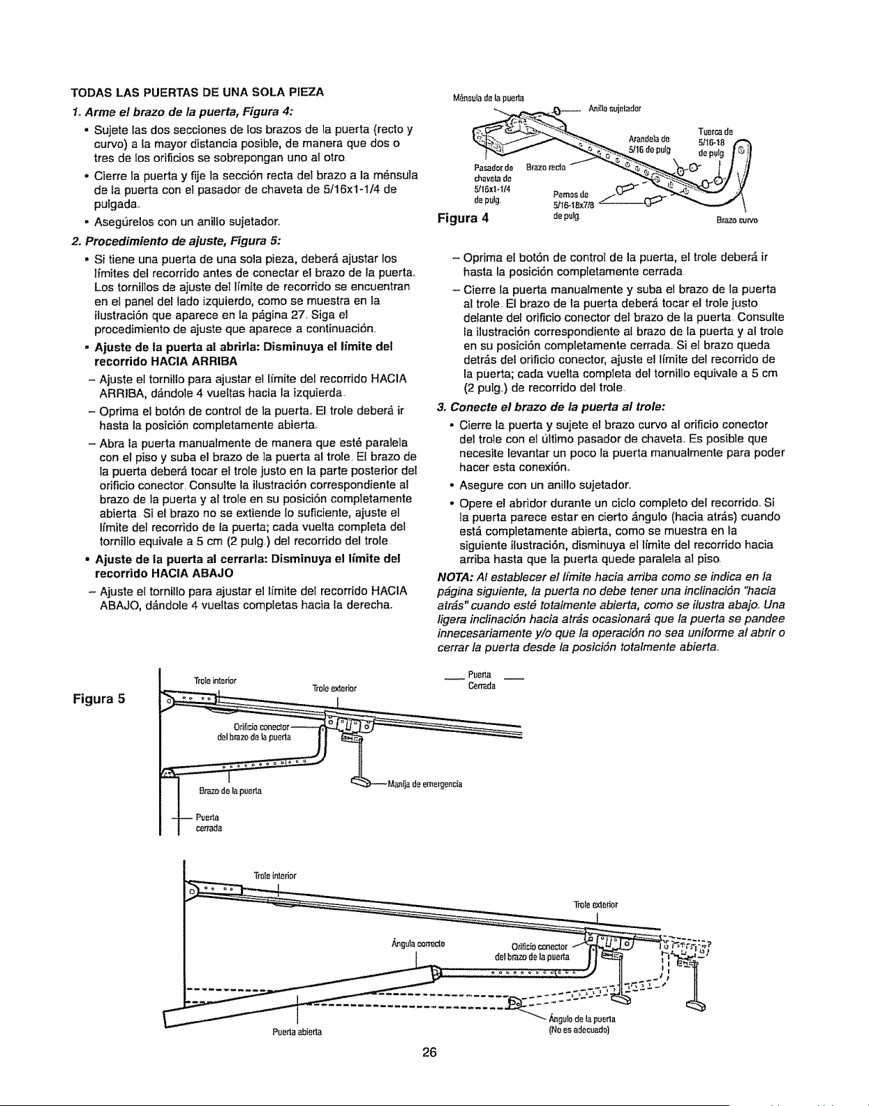
TODAS LAS PUERTAS DIEUNA SOLA PIEZA
1. Arme el brazo de ta puerta, Figura 4:
. Sujete las dos secciones de fos brazos de la puerta (recto y
curvo) a la mayor distancia posible, de manera que dos o
tres de los orificios se sobrepongan uno al otto
• Cierre la puerta y fije ta secciSn recta del brazo a la m_nsula
de la puerta con el pasador de chaveta de 5t16x1-1t4 de
pulgada,
,, AsegSrelos con un anillo sujetador,
2. Procedimiento de ajuste, Figura 5:
• Si tiene una puerta de una sola pieza, deber_ ajustar los
Ifmites del recorrido antes de conectar el brazo de la puerta_
Los tornillos de ajuste det lfmite de recorrido se encuentran
en el panel de! lado izquierdo, como se muestra en la
ilustraci6n que aparece en la p_gina 27. Siga el
procedimiento de ajuste que aparece a continuaciSn,,
= Ajuste de la puerta al abrirla: Disminuya el iimite del
recorrido HACIA ARRIBA
- Ajuste el tornillo para ajustar el lfmite del recorrido HACIA
ARRIBA, d_,ndole 4 vuettas hacia la izquierda.
- Optima el botSn de control de la puertao El trole deber,i ir
hasta la posiciSn completamente abierta,,
- Abra ia puerta manuatmente de manera que est_ paralela
con el piso y suba el brazo de ]a puerta al trole, El brazo de
la puerta deber_,tocar el trole justo en la parte posterior del
orificio conector, Consulte la ilustraciSn correspondiente al
brazo de la puerta y al trole en su posiciSn completamente
abierta Si el brazo no se extiende lo suficiente, ajuste el
lfmite del recorrido de la puerta; cada vuelta completa del
tornillo equivale a 5 cm (2 pulg,.) del recorrido del trole
• Ajuste de ta puerta al cerrarla: Disminuya el limite det
recorrido HACIA ABAJO
- Ajuste el tornillo para ajustar el Ifmite del recorrido HACIA
ABAJO, d,i,ndole 4 vueltas completas hacia la derecha,.
Figura 5
Tr01einterior
Tr01e_edor
M6nsula d_ la pueda
Figura 4 depulg, Brazoc_rv0
- Oprima e{ botSn de control de la puerta, et trole deber_, ir
hasta la posiciSn completamente cerrada
- Cierre fa puerta manualmente y suba el brazo de la puerta
at trole El brazo de la puerta deber_ tocar el trole justo
delante del orificio conector det brazo de fa puerta Consulte
la ilustraciSncorrespondiente al brazo de la puerta y al trole
en su posiciSn completamente cerrada.. Si el brazo queda
detr_s del orificio conector, ajuste el Ifmite de! recorrido de
la puerta; cada vuelta completa det tornitlo equivale a 5 cm
(2 pulg,) de recorrido del trole
3. Conecte el brazo de la puerta at trole:
,, Cierre la puerta y sujete el brazo curvo al orificio conector
del trole con el L_ltimopasador de chaveta., Es posible que
necesite levantar un poco la puerta manualmente para poder
hacer esta conexiSn,,
, Asegure con un anilio sujetador,.
• Opere el abridor duran|e un ciclo completo del recorrido, Si
la puerta parece estar en cierto _ngulo (hacia atr_s) cuando
est_ completamente abierta, como se muestra en la
siguiente HustraciSn, disminuya el Hmite del recorrido hacia
arriba hasta que la puerta quede paralela al piso.
NOTA: Af establecer el t[mite hacia arriba como se indica en la
p_gina siguiente, la puerta no debe tener una inctinaciSn "hacia
atr_s" cuando est6 totafmente abierta, como se itustra abajo.. Una
ligera inclinaciSn hacia atr_s ocasionar& que ta puerta se pandee
innecesariamente y/o que ta operacidn no sea uniforme at abrir o
cerrar la puerta desde la posicidn totatmente abierta.,
Tmlein_.edor
Puerla_ierta
26
- _gutode lapuerla
(Noesadect_ado)
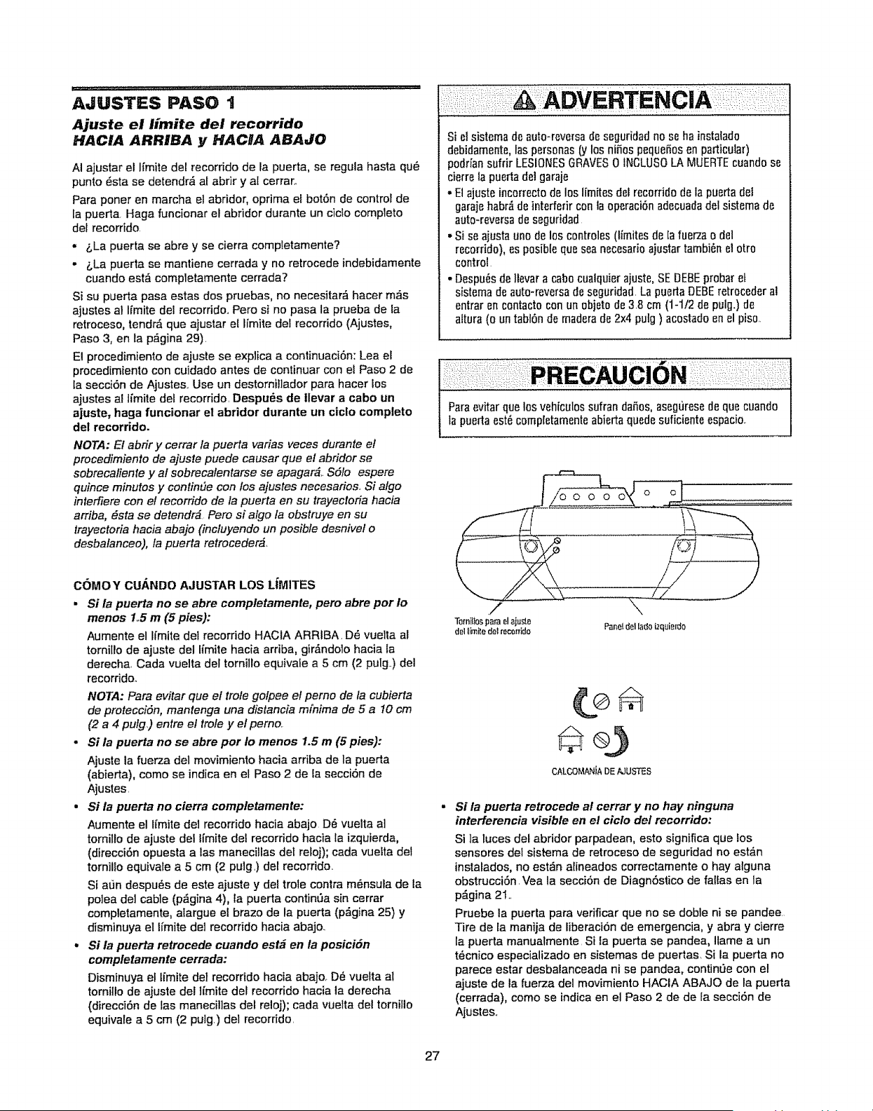
.... _: =:.............................. ,...1, ,,,,_,_,,L,,,,,,,,,,,_ ,,,, ,,
AaUSTES PASO 1
Ajuste el limite del recorrido
HACIA ARRIBA y HACIA ABAJO
AI ajustar el lfmite def recorrido de la puerta, se regula hasta qu_
punto _sta se detendr_ al abrir y al cerrar.
Para poner en marcha el abridor, oprima el bot6n de control de
la puerta, Haga funcienar el abridor durante un ciclo complete
del recorrido
• _,La puerta se abre y se cierra comptetamente?
- &La puerta se mantiene cerrada y no retrocede indebidamente
cuando est_ completamente cerrada?
Si su puerta pasa estas dos pruebas, no necesitar& hacer m_s
ajustes al Ifmite del recorrido.. Pero si no pasa la prueba de la
retroceso, tendr_ que ajustar el Ifmite det recorrido (Ajustes,
Paso 3, en la p#.gina 29).
E! procedimiento de ajuste se explica a continuaciSn: Lea el
procedimiento con cuidado antes de continuar con el Paso 2 de
la secci6n de Ajustes. Use un destornillador para hacer los
ajustes al lfmite del recorrido. DespuRs de Ilevar a ¢abo un
ajuste, haga funcionar el abridor durante un ciclo complete
del recorrido.
NOTA: E/abdr y cerrar la puerta varias veces durante e/
procedimiento de ajuste puede causar que el abridor se
sobrecaliente y al sobrecalentarse se apagar&.. $51o espere
quince minutes y continEte con los ajustes necesarios. Si algo
interfiere con el recorrido de la puerta en su trayectoria hacia
arriba, #sta se detendr# Pero si algo ta obstruye en su
trayectoria hacia abajo (incluyendo un posible desnivel o
desbalanceo), la puerta retrocecler_.
COMOY CU/_NDO AJUSTAR LOS LIMITES
Si la puerta no se abre completamente, pete abre per Io
menos 1.5 m (5 pies):
Aurnente el lfmite del recorrido HACIA ARRIBA, DR vuelta al
tornillo de ajuste del limite hacia arriba, gir,_ndolo hacia la
derecha, Cada vuelta del tornillo equivale a 5 cm (2 pulg..) del
recorrido,,
NOTA: Para evitar que el trole golpee el perno de fa cubierta
de protecciSn, mantenga una distancia mfnima de 5 a 10 cm
(2 a 4 pulg,) entre el trole y e! pemo.
. Si la puerta no se abre per to menos 1.5 m (5 pies):
Ajuste la fuerza del movimiento hacia ardba de la puerta
(abierta), come se indica en el Paso 2 de la secciSn de
Ajustes,
• Si ta puerta no cierra completamente:
Aumente el l_mitedel recorrido hacia abajo DR vuelta a]
tornillo de ajuste del lfmite del recorrido hacia la izquierda,
(direcci6n opuesta a tas manecillas det retoj); cada vuefta del
tornillo equivale a 5 cm (2 pulg,) del recorrido.
Si atJn despu_s de este ajuste y del trote contra m_nsula de la
polea del cable (p6gina 4), la puerta continOa sin cerrar
completamente, alargue el braze de la puerta (p_.gina 25) y
disminuya el l_mite del recorrido hacia abajo.
• $i la puerta retrocede cuando est_ en la posiciSn
completamente cerrada:
Disminuya el limite det recorrido hacia abajo,.D_ vuelta al
tomitlo de ajuste del li'mite del recorrido hacia la derecha
(direcci6n de las manecillas del reloj); cada vuelta del tornitlo
equivale a 5 cm (2 pulg,) del recorddo,
Si el sistema de auto-reversad_ seguridadno se ha instalado
debidamente,faspers0nas (y 10snifi0s p{,,queSosen particular)
podriansufrir LESIONESGRAVES0 INCLUS0LA MUERTEcuandose
cierr_ la puerta delgaraje
• El ajusteincorrectode los limites det recorrido de la puertadel
garajehabr_Beinterfefircon laop_raciSnadecuadadel sistemade
auto-rewrsa de seguridad
• Si se ajusta unode los c0ntroles (limites de [a fuer-zao del
recorddo), es p0sible que s_anecesarioaiustar tarnbi_nel otto
control
. Despu_sde llevara cabocualquierajuste,SE DEBEpr0bar et
sistema de auto-reversadeseguridad,La puerta DEBEretrocederal
entrar encontacto con un 0bjeto de 3,8 cm (1-1/2 d_ pulg.) de
altura (o un tabl6n de mad_rade 2x4 pulg ) ac0stadoen el piso,,
DO 0 0
TomilIosp_raelajus_o
deltimitedel recorfido
Paneldel lad0izq_ierdo
CALCOMANIADEtJUSTES
Si la puerta retrocede al cerrar y no hay ninguna
interferencia visible en el ciclo del recorrido:
Si la tuces del abridor parpadean, esto significa que los
sensores del sistema de retroceso de seguridad no est,_n
instalados, no estdn alineados correctamente o hay alguna
obstrucci6n, Vea la secciSn de Diagn6stico de fallas en la
p_gina 21,,
Pruebe la puerta para vedficar que no se doble ni se pandee
Tire de la manija de liberaci6n de emergencia, y abra y cierre
la puerta manualmente, Si la puerta se pandea, Ilame a un
t_cnico especializado en sistemas de puertas. Si la puerta no
parece estar desbalanceada ni se pandea, continr3e con el
ajuste de la fuerza del movimiento HACIA ABAJO de la puerta
(cerrada), come se indica en el Paso 2 de de la secci6n de
Ajustes,,
27
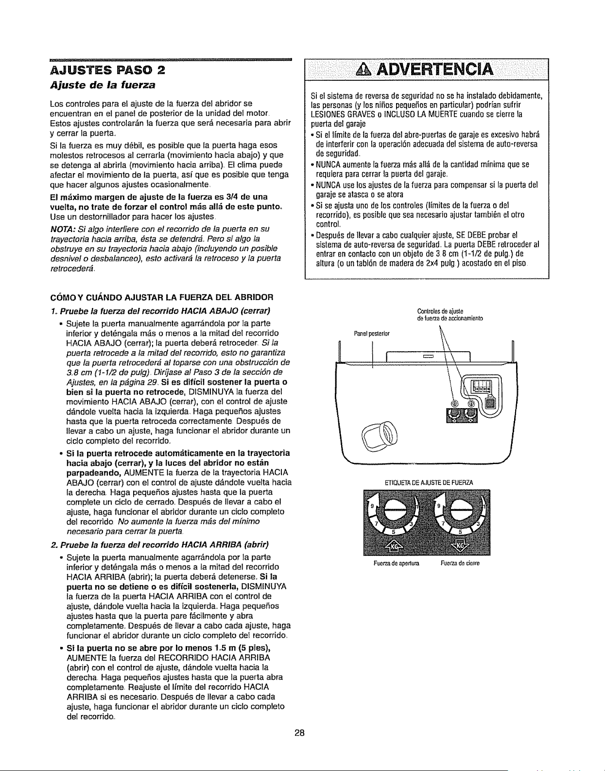
AJUSTES PASO 2
Ajuste de la fuerza
Los controles para el ajuste de la fuerza del abridor se
encuentran en el panel de posterior de la unidad del motor.
Estos ajustes controlar_n la fuer-za que ser,_ necesaria para abrir
y cerrar la puerta,
Si la fuerza es muy d_bit, es posible que la puerta haga esos
molestos retrocesos al cerrada (movimiento hacia aba}o) y que
se detenga al abrirla (movimiento hacia arriba), El clima puede
afectar el movimiento de la puerta, ast que es posible que tenga
que hacer algunos ajustes ocasionalmente,
El m_ximo margen de ajuste de la fuerza es 314 de una
vuelta, no trate de forzar el control mrs a!l_ de este puntoo
Use un destornillador para hacer los ajustes.
NOTA: Si algo intediere con el recorrido de fa puerta en su
trayectoria hacia arriba, _sta se detendr_, Pero si algo ta
obstruye en su trayectoria hacia abajo (incluyendo un posible
desnivel o desbalanceo), esto activar_ fa retroceso y fa puerta
retroceder_,
Si el sistema de reversade seguridadno se ha instalad0debidamente,
las personas (y los niSos pequeSosen particular)podrian sufrk
LESIONESGRAVESo INCLUSOLA MUERTEcuandose cierre la
puertadei garaje
. Si el limite de lafuerzadet abre-puertasde garajees excesivo habr_
de interferircon la opcraci6nadecuadadel sistema de auto-reversa
de seguridad,
* NUNCAaumente lafuerzam_salt_ de la oantidadminima quese
requieraparacerrar la puertadW gara}e,,
-NUNCA use los ajustesde fafuerza para compensarsi la puerta dcl
garaje seatascao seatora
- Si seajusta uno d_ los controles(limites de la fuerzao de1
recorrid0), es posibleque sea necesarioajustar tambi_n el otro
control,
. Despu_sdellevara cabooualquieraiuste, SEDEBEpr0barel
sistemade auto-reversadeseguridad,La puerta DEBEretrocederal
entrar en contact0conun objeto de 38 cm (1-1/2 de pWg.)de
altura (o un tabl6n de maderade 2x4 pulg) acostadoen el piso
COMO Y CUANDO AJUSTAR LA FUERZA DEL ABRIDOR
1. Pruebe ta fuerza de/recorrido HACIA ABAJO (cerrar)
,, Sujete la puerta manualmente agarrdndota por ta parte
inferior y det_ngala m,_so menos a la mitad del recorrido
HACIA ABAJO (cerra0; fa puerta deber_ retroceder Si la
puerta retrocede a ta mitad del recorrido, esto no garantiza
que la puerta retroceder_ al toparse con una obstruccidn de
3,,8 cm (1-1/2 de pulg), Dir[jase al Paso 3 de la secci6n de
Ajustes, en la p_gina 29. Si es dificil sostener la puerta o
bien si la puerta no retrocede, DISMINUYA ]a fuerza det
movimiento HACIA ABAJO (cerrar), con el control de ajuste
d_ndole vuelta hacia la izquierda. Haga pequeSos ajustes
hasta que la puerta retroceda correctamente Despu6s de
!levar a cabo un ajuste, haga funcionar el abridor durante un
ciclo completo del recorrido,
• Si la puerta retrocede autom_ticamente en la trayectoria
hacia abajo (cerrar), y la luces del abridor no est_n
parpadeando, AUMENTE la fuerza de la trayectoria HAClA
ABAJO (cerrar) con el control de ajuste ddndole vuelta hacia
la derecha Haga peque_os ajustes hasta que la puerta
complete un ciclo de cerrado,, Despu6s de Ilevar a cabo el
ajuste, haga funcionar et abridor durante un cicto completo
del recorrido No aumente la fuerza m_s del mfnimo
necesario para cerrar la puerta,
2. Pruebe la fuerza det recorrido HACIA ARRIBA (abrir)
• Sujete la puerta manualmente agarr,_ndota pot ]a parte
inferior y det_ngala m_.s o menos a la mitad del recorddo
HAC1A ARRIBA (abrir); la puerta deber& detenerse,, Si la
puerta no se detiene o es dificil sostenerla, DISMINUYA
la flJerza de la puerta HACIA ARRIBA con e! control de
ajuste, d_ndole vuetta hacia la izquierda,, Haga pequeSos
ajustes hasta que la puerta pare f_cilmente y abra
completamente,, Despu_s de llevar a eabo cada ajuste, haga
funcionar el abddor durante un ciclo compteto det recorrido,
• Si la puerta no se abre por Io menos 1.5 m (5 pies),
AUMENTE la fuerza del RECORRIDO HACIA ARRIBA
(abrir) con el control de ajuste, d_,ndole vuelta hacia ta
derecha Haga pequefios ajustes hasta que la puerta abra
completamente, Reajuste el limite del recorrido HACIA
ARRIBA si es necesado, Despu6s de llevar a cabo carla
ajuste, haga funcionar el abridor durante un ciclo completo
del recorrido.,
28
CanlrolesdeaIuste
de iue_a de ar.cionamiento
Pane!posterior _\
II = i ......
_TIQUETADE/_]USTQDE FUERZA
Fuerzade aperlura Fua,,-zade rJel_m
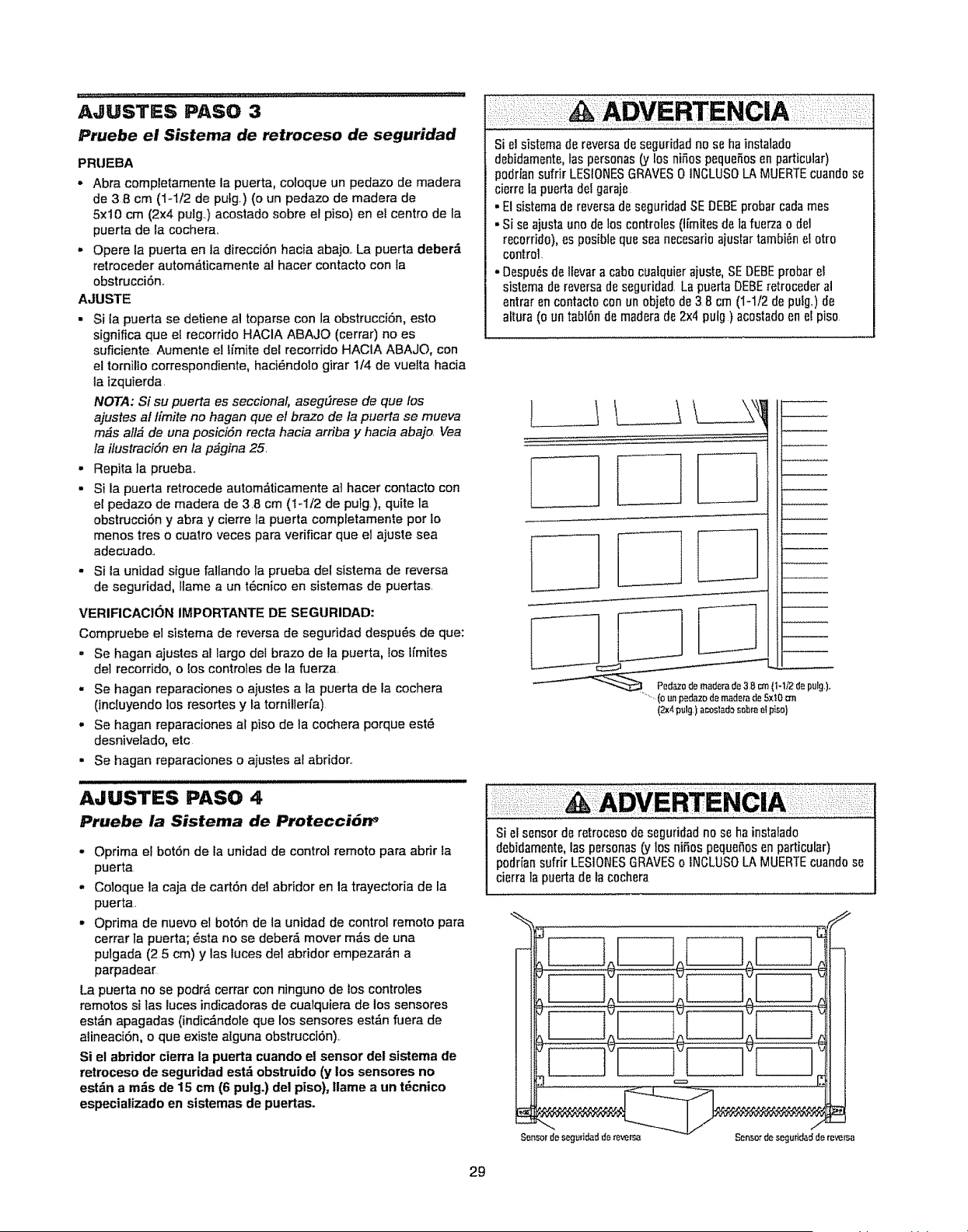
AJUSTES PASO 3
Pruebe el Sistema de retroceso de seguridad
PRUEBA
• Abra completamente la puerta, coloque un pedazo de madera
de 38 cm (t-1t2 de pufg.) (o un pedazo de madera de
5x10 cm (2x4 pulg,) acostado sobre el piso) en el centro de la
puerta de Ia cochera,,
- Opere la puerta en la direcci6n hacia abajo.. La puerta deber_
retroceder autom6ticamente al hacer contacto con la
obstrucci6n.
AJUSTE
. Si ta puerta se detiene al toparse con la obstrucci6n, esto
significa que el recorddo HACIA ABAJO (cerrar) no es
suficiente Aumente el ti'mite del recorrido HACIA ABAJO, con
el tornilIo correspondiente, haci6ndolo girar 1/4 de vuelta hacia
la izquierda,
NOTA: Si su puerta es seccional, aseg_rese de que los
ajustes al Ifmite no hagan que el braze de la puerta se mueva
m_s al!_ de una posici6n recta hacia arriba y hacia abajo. Vea
la ilustracidn en la p_gina 25,
. Repita la prueba,,
• Si la puerta retrocede autom6ticamente al hacer contacto con
el pedazo de madera de 3,8 cm (1-1/2 de putg), quite la
obstrucciSn y abra y cierre la puerta completamente por !o
menos tres o cuatro veces para verificar que el ajuste sea
adecuado,,
- Si la unidad sigue fallando la prueba del sistema de reversa
de seguridad, flame a un tE,cnico en sistemas de puertas,
VERIFICACION IMPORTANTE DE SEGURIDAD:
Compruebe el sistema de reversa de seguddad despu6s de que:
,, Se hagan ajustes al largo del brazo de la puerta, los ffmites
del recorrido, o los controles de la fuerza,
- Se hagan reparaciones o ajustes a _apuerta de ta cochera
(inctuyendo los resortes y ta tornilierfa)
• Se hagan reparaciones al piso de la cochera porque est6
desnivelado, etc
. Se hagan reparaciones o ajustes af abridor.,
AJUSTES PASO 4
Pruebe la Sistema de Protecci_n _
• Oprima el botOn de la unidad de control remoto para abrir la
puerta
• Coloque la caja de cart6n de1abridor en la trayectoria de la
puerta,
• Oprima de nuevo et botOn de la unidad de control remoto para
cerrar la puerta; 6sta no se deber_i mover m_s de una
pulgada (25 cm) y ]as luces de1 abridor empezar_n a
parpadear
La puerta no se podr_ cerrar con ninguno de los controles
remotos si las luces indicadoras de cualquiera de los sensores
est&n apagadas (indic_ndole que los sensores est,_n fuera de
alineaciOn, o que existe alguna obstrucci6n),
Si el abridor cierra la puerta cuando el sensor del sistema de
retroceso de seguridad est_ obstruido (y los sensores no
est_n a m_s de 15 cm (6 pulg.) del piso), tlame a un t_cnico
especiatizado en sistemas de puertas.
Siel sistema de reversade seguridadno se ha instalad0
debidamente,las personas(y Eosni_os pequefiosen particular)
p0dfiansufrir LESIONESGRAVES0 INCLUSOLA MUERTEcuandose
cierre la puertadel garaje
. El sistema dereversade seguridadSE DEBEprobar cadarues
. Si se ajustauno de los c0ntrotes (Ifmitesde tafue_a o del
recorrido), es posible quesea necesarioajustartambi_nel otro
control,
. Despu6sde Ifevara cabocualquierajuste, SEDEBEprobarel
sistema de reversade seguridad,La puertaDEBEretrocederal
entrar en contacto conun objeto de 38 cm (1-1/2 de pulg,) do
altura (o un tablOnde maderade 2x4pulg) ac0stadoen e! piso
_1 1/2de pulg)
........(oun pedazodemad_rade 5xtO_nn
(2x4pulg,)ar.oslados0bme_piso)
Si el sensor de retroces0de seguridadno se ha instalado
debidamente,las personas(y Ins nifi0s pequefiosen particular)
podrian sufrir LESIONESGRAVESo INCLUS0LA MUERTEcuandose
cierra la puertade la cochera
%,
Sensordeseg_idad d_ reversa
=___
Senso_desegutid_dde reversa
29
OPERACH_N
INSTRUCCIONES DE SEGURiDAD iMPORTANTES
I,
2
Para reducir el riesgo de LESIONES GRAVES o
LA MUERTE:
LEAY RESPErETODASLASADVERTENCIASE INSTRUCCIONES 9. Cuandose aiusta uno de los controles(limites de fuerzao de
StEMPREconservelos centroles remotos lejos del atcancede los
ni_os. NUNCApermita quelos niSos opereno joeguencon los
botones del control del abre-puertasde garaje ni con los controles
remotos
3, SOLOactive el abre-puertasde garajesiemprey cuandoest6a
plenavista, correctamentecalibradoy no hayaninguna obstrucci6n
en el rec0rrido de la puerta,
4 TongaSIEMPREla puerta dotgarajea la vista hastaque est6
completamentecerrada,NADIEDEBEATRAVESAREL RECORRIDO
DELA PUERTACUANDOESTAEN MOVIMIENTO.
5 NODEJAR PASARA NADIEPORDEBAJODE UNA PUERTADE
GARAJEDETENIDA,NI PARCIALMENTEAB1ERTA.
6, Deser posible, useeldesenganchede emergenciapara soltar el
trole, SOLOcuandola puerta del garajeest6 CERRADA,Si los
resortes est_indebititadoso rotos, o si la puerta estfi
desbalanceada,podriacaerse r,_pidae inesperadamente
7. NUNCAuse ta maniladeldesenganchede emergenciaa menos qua
ta entradaal garajeest6libre de obstruccionesy no hayaninguna
personaen el camino
8 NUNCAuse la manilapara abrir o cerrarlapuerta.Si et nudode la
cuerdase desatara,usted podria caerse.,
recorrido), es posibieqoe sea necesarioa}ustar:arabianel otto
control
I0, Despu6sde Ilevara cabocualquierajuste, SEDEBEprobar el
sistema de reversade seguridad
11 Et sistema de reversado seguridadSEDEBEprobar carlarues La
puerta DEBEinvertir su direcciOnal entrar encontactocon un
objeto de 3,8 cm (1-1/2 de pulg,)de altura (o un tabt6nde madera
de 2x4 pulg ) apoyadosobreel piso
I2, MANTENGASIEMPRELA PUERTADELGARAJEDEBtDAMENTE
BALANCEADA(v6asela p;_gina3). Si fa puerta no estfi
debidamentebalanceadaes posible que no retroceda cuandoasi
se requieray podria ocasionaruna LESIONACCIDENTALGRAVEo
INCLUSOLA MUERTE
13 TODASlas reparacionesnecesariasde cables,resortes y otras
piezaslas DEBEilevar a caboun t_cnicoespecializadoen sistemas
de puertas,puesTODASestaspiezasest_n bajounatensi6n
EXTREMA
14 SIEMPREdesconectela alimentaci6nde energiael_ctricaal
abre-puertasde garajeANTESde lfevara cabo cualquier
reparaciOno dequitar las tapas
Is. CONSERVEESTASINSTRUCCIONES.
i J JJJJJii HHJHHHJL,
Cfimo usar su abridor de puerta de cochera
Su abridor Security,!- y et control remoto manual han side
programados en la _brica con un c6digo coincidente que cambia
cada vez que se usa, accesando at azar m_s de 100,000
millones de c6digos nuevos Su abridor funcionar_ hasta con 8
controles remotos Security4., yun sistema de entrada sin llave
Security.l,.,. Si compra un control remoto nuevo, o si desea
desactivar atg_n control remoto, siga las instrucciones que
aparecen en la secci6n sobre Cdmo programar el abridor.
Active su abridor de aiguna de las siguientes maneras:
. E! Control remoto manuaL:Mantenga oprimido el bot6n grande
hasta que la puerta se empiece a mover.
• El Control de pared de la puerta: Mantenga oprimido el bot6n
hasta que la puerta se empiece a mover,
• La Entrada sin tlave (Vea Accesorios): Si su abridor de puerta
de cochera viene con este accesorio, deberfi estar
programado antes de usarlo, Vea Cdmo programar el abridor.
Una vez activado el abridor (con el sensor de seguridad de
retroceso correctamente instatado y alineado)
1• Si la puerta est_ abierta se va a cerrar_Si la puerta est_
cerrada se va a abrir.,
2 Si la puerta se estfi cerrando va a retroceder,,
3, Si la puerta se est', abriendo se va a detener,
4., Si la puerta se ha detenido en un punto parcialmente abler:a,
se va a cerrar,
5, Sial cerrarse la puerta se top6 con alguna obstrucci6n, va a
retroceder., Si la obstrucci6n interrumpe el rayo del sensor, las
luces del abridor van a parpadear durante cinco segundos,,
6, Si al abrirse la puerta se top6 con alguna obstrucci6n, se va a
detener_
7,,Si la puerta est_ completamente abierta, no va a cerrar si el
rayo est& interrumpido.. El sensor no tiene ningLin efecto en el
ciclo de aperturao
Si el sensor no se ha instalado o est,_ desalineado, la puerta no
se cerrar& con et control remoto manual. Sin embargo, la
puerta se puede cerrar con el Control de la puerta, el
Interruptor de Ilave externo, o la Entrada sin leave,siempre y
cuando los active hasta que et recorrido hacia abajo haya
terminadoo Si los suelta demasiado pronto, ta puerta va a
retroceder__.,
Las luces del abridor se encender_n en los siguientes casos:
Siempre que conecte el abridor inicialmente;cuando se restaura
el suministro de energfa despu6s de una interrupci6n; cuando el
abridor se activa
Las luces se apagan autom_ticamente despu6s de 4 minutos y
1/2 o se quedan encendidas cuando se activa Luz en la consola
de control premium., Los bombil[os deben set de A19,, El poder
de ta bombiIla es 100 m_ximo de vatios,,
La funci6n de la luz dei Security+,: Las luces se encender_n
tambi6n si alguien camina pot la puerta de la coehera cuando
est_ abierta,, Si tiene la consola de controlpremium, esta funci6n
puede desactivarse como sigue: Con las luces del abridor
apagadas, optima y mantenga oprimido el bot6n de la luz
durante 10 segundos hasta queta luz se encienda y se apague
de nuevo Para volver a activar esta funci6n, empiece el
procedimientocon las tuces encendidas, fuego oprima y
mantenga oprimido e! bot6n de la luz durante 10 segundos hasta
que la luz se apague y luego se encienda de nuevo
3O
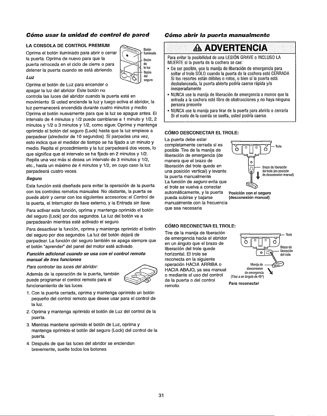
C6mo usar la unidad de control de pared
LA CONSOLA DE CONTROL PREMIUM
Oprima el bot6n iluminado para abdr o cerrar
la puerta, Oprima de nuevo para que la
puerta retroceda en el ciclo de cierre o para
detener la puerta cuando se est,, abriendo.
Luz
Oprima et bot6n de Luz para encender e
apagar la luz del abrido_ Este botSn no
,. Bot6n
_ l[uminad0
:}_ Ialuz
Bot6n
IId_I
I,J seguro
controla las tuces del abridor cuando la puerta est_ en
movimiento, Si usted enciende ia iuz y luego activa ei abridor, la
luz permanecer& encendida durante cuatro minutes y medio.
Oprima el bot6n nuevamente para que la luz se apague antes, Ei
intervalo de 4 minutes y t/2 puede cambiarse a 1 minute y 1/2, 2
minutes y 1/2 o 3 minutes y I/2, come sigue: Oprima y mantenga
oprimido et botSn dei seguro (Lock) hasta que ta luz empiece a
parpadear (alrededor de 10 segundos)._Si parpadea una vez,
esto indica que el medidor de tiempo se ha fijado a un minute y
medio. Repita el procedimiento y la luz parpadear_ dos veces, Io
que significa que el intervalo se ha fijado en 2 minutes y 1/2.,
Repita una vez m&s si desea un intervalo de 3 minutes y 1/2,
etc,, hasta un m_ximo de 4 minutes y 1/2, en cuyo case la Iuz
parpadear_, cuatro veces.
Seguro
Esta funci6n est_ diseSada para evitar la operaci6n de la puerta
con los controies remotos manuales No obstante, la puerta se
puede abrir y cerrar con fos siguientes accesorios: ei Control de
la puerta, el Interrupter de llave externo, y la Entrada sin ,ave,
Para activar esta flJnci6n, oprima y mantenga oprimido el bot6n
del seguro (Lock) per dos segundos, La luz del bot6n va a
parpadear_n mientras est6 activado el segure,
Para desactivar la funci6n, oprima y mantenga oprimido el bot6n
deI seguro per dos segundos, La luz del bot6n dejaM de
parpadear,. La funci6n del seguro tambi_n se apaga siempre que
el bot6n "aprender" det panel del motor est_ activado.
FunciSn adicional cuando se usa con et control remoto
manual de tres funciones
Para controlar /as luces de/abridor:
Adem_s de la operaci6n de ta puerta, tambi6n
puede programar el control remote para el
funcionamiento de tas luces,
1,,Con la puerta cerrada, oprima y mantenga oprimido un bot6n
pequeSo dei control remote que desee usar para el control de
la luz..
2, Oprima y mantenga oprimide el bot6n de Luz del control de la
puerta_
3, Mientras mantiene oprimido el boron de Luz, oprima y
mantenga oprimido el bot6n del seguro (Lock) del control de la
puerta.
4. Despu6s de que las tuces del abridor se enciendan
brevemente, suelte todos los botones.
C_mo abrir ia puerta manualmente
Paraevitar la posibilidaddeunaLESIONGRAVE0 INCLUSOLA
MUERTEsi la puertade la cocherase cae:
• Deser p0sible,use la manijade liberaci6nde emergenciapara
sottar el trole SOLOcuandola puertade ia cocheraest_ CERRADA
Si 10sresortes est_nd_bileso rot0s, o bien si la puertaest,_
desbatanceada,la puertaabiertapodr{acaerse#,pida y/o
inesperadamente
• NUNCAuse la manijade liberaci6nde emergenciaa men0s que la
entradaa la cocheraest6Iibre de obstruccionesy no hayaninguna
personapresente
o NUNCAuse la manijapara tirar de la puertapara abridao cerrarla
Si el nude de la cuerdase suelta,usted p0dria caerse,,
COMO DESCONECTAR EL TROLE:
La puerta debe estar
completamente cerrada si es
posible, Tire de Eamanija de
IiberaciOn de emergencia (de
manera que e! braze de
liberaci6n del trole quede en
una posici6n verticaD y levante
la puerta manualmente
La funciOn de seguro evita que
el trole se vuetva a conectar
automa'ticamente, y la puerta
pueda subirse y bajarse
-- Tmle
Ifl_-_ Brazode I;beraci6n
_"_] . detlrole(enposici6n
$ d_des{onex_'onmanual)
Posici6n con el seguro
(desconexi6n manual)
manuaimente con la frecuencia
que sea necesaria
COMO RECONECTAR EL TROLE:
Tire de la manija de liberaci6n
de emergencia hacia el abridor
en un ,_ngulo que el braze de
tiberaci6n clel trole quede
horizontal Et trole se
reconecta en ta siguiente
operaci6n HACIA ARRIBA o
HACIA ABAJO, ya sea manual
o mediante el use del control
de la puerta o del control
remote,
"---%=__ a_ode
lib_raci6n
L_-_ delImle
M_ija do
d_conex_'on
de emer_encia '_
O'ira_aun_gulode45°1
Para reconectar
31
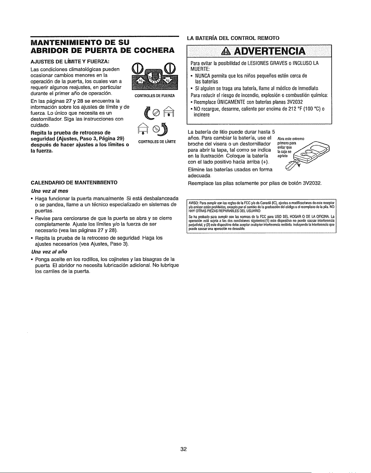
MANTENIMIENTO DE SU
ABRIDOR DE PUERTA DE COCHERA
AJUSTES DE LIMITE Y FUERZA:
Las condiciones climatol6gicas pueden
ocasionar cambios menores en la
operaci6n de la puerta, los cuales van a
requerir aEgunos reajustes, en particular
durante el primer aSo de operaci6n.,
En fas p,_ginas 27 y 28 se encuentra ta
informaci6n sobre fos ajustes de Ifmite y de
fuerza, Lo _nico que necesita es un
destornillador,, Siga tas instrucciones con
cuidado,
Repita la prueba de retroceso de
seguridad (Ajustes, Paso 3, P_gina 29)
despu_s de hacer ajustes a los limites o
la fuerza,,
COh_ROLES DE FUERZA
COfGROLESDE LIMIT£
CALENDARIO DE MANTENIMIENTO
Una vez al rues
, Haga funcionar la puerta manualmente Si est_ desbalanceada
o se pandea, Ilame a un t_cnico especializado en sistemas de
puertas,
. Revise para cerciorarse de que ta puerta se abra y se cierre
completamente Ajuste los limites y!o la fuerza de ser
necesario (yea las p&ginas 27 y 2B)..
- Repita ta prueba de la retroceso de seguridad Haga los
ajustes necesarios (vea Ajustes, Paso 3).,
Una vez al afio
• Ponga aceite en los mdiilos, los cojinetes y Easbisagras de Ia
puerta El abridor no necesRa lubricaci6n adicionaL No lubrique
los carriles de la puerta_
LA BATER|A DEL CONTROL REMOTe
Paraevitar la posibilidadde LESIONESGRAVESo INCLUSOLA
MUERTE:
• NUNCApermita que _0sniSos peque_osest_n cercade
lasbaterias
• Si alguiense traga una baterfa,Hameal mMico de inmediat0,
Para reducir el riesgo de incendio, explosi6no combusti6n quimfca:
• ReemplaceONtCAMENTEcon bateriasplanas3V2032
- NOrecargue,desarme,caliente per encima de 212 °F (100 °C) o
incinere
La batefia de litio puede durar hasta 5
ar3os.,Para cambiar fa baterfa, use el Abrae_e_remo
broche det visera o un destornillador
para abrir la tapa, tal come se indica
en la itustraci6n Coloque la baterfa
con et lade positivehacia arriba (+),
Elimine tas baterfas usadas en forma
adecuada.
Reemplace las pilas solamente per pilas de bot6n 3V2032,,
I AVISO: Para cump_itconlas tug,as do ia FCC ylo de Ca_a_ ($C),ajusies o m_ificaclones de este receptor
ylo emi_or est_ prohib_dos,ex_pie per el c,_nbiode la graduac_6nde! c_go o e_reemptazode fa p_'l_. NO
HAY OTRAS PfEZAS REPAFIABLES DEL USUARID
_qeha proSado para cump_ir c_n l_snormas de laFCC par_ use DEL HOGAR 0 DE LA OFICtNA. La
oper_cibnest_ sujet_ alas dos _n_c_onos sig_onles:(1) es_e d_spo_ n_ _de causar intorfe_ancia
per_udJda_,y (2) osio [_spositivo d_boaceplar _aJq'_er it_tede=enrJare_'bid_ Indwe_do la interf_rencia q_o
pue_a caus._tu_ _per_d6n no des_blo.
32
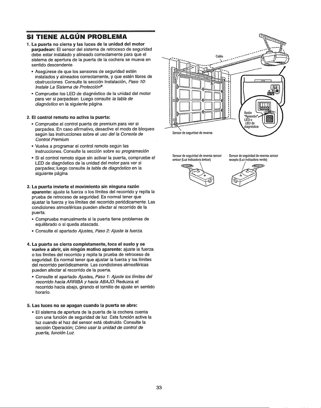
S! TIENE ALGUN PROBLEMA
1. La puerta no cierra y las luces de la unidad del motor
parpadean: El sensor del sistema de retroceso de seguridad
debe estar instalado y alineado correctamente para que el
sistema de apertura de la puerta de la cochera se mueva en
sentido descendente
• Asegurese de que los sensores de seguridad est_n
instalados y alineados correctamente, y que est6n fibres de
obstruccionesr Consulte la secciSn Instalaci6n, Paso 10:
Instate La Sistema de ProtecciSn _
- Compruebe los LED de diagn6stico de la unidad del motor
para ver si parpadean Luego consutte fa tabla de
diagndstico en la siguiente p,_gina
2. El control remoto no activa la puerta:
• Compruebe et control puerta de premium para ver si
parpadea En caso afirmativo, desactive el modo de bloqueo
seg_n las instrucciones sobre el uso delta Consola de
Control Premium,
- Vuetva a programar el control remoto segun las
instrucciones,,Consutte la secci6n sobre su programacidn
- Si et control remoto sigue sin activar la puerta, compruebe el
LED de diagn6stico de la unidad del motor para ver si
parpadea; luego consulte la tabla de diagndstico en la
siguiente p_gina
3. La puerta invierte et movimiento sin ninguna raz6n
aparente: ajuste la fuerza o los Ifmites del recorrido y repita la
prueba de retroceso de seguridad_ Es normal tener que
ajustar ta fiJerza y los Ifmites del recorrido peri6dicamente. Las
condiciones atmosf_ricas pueden afectar al recorrido de la
puerta.
. Compruebe manualmente si la puerta tiene problernas de
equilibrado o si queda atascada,
• Consulte el apartado Ajustes, Paso 2:' Ajuste fa fuerza.,
Cable .-_"°'*''""
Sensord_ seguridadderevi_rsa
Sensordesegu]rdadd_ re_rsa sensor SensorBeseguirdadde reversas_nsor
emisor(LuzIndicadoraf_bar} receplo(Luzindicad(_raverde)
4. La puerta se cierra comptetamente, toca el suelo y se
vuelve a abrir, sin ningdn motivo aparente: ajuste la fuerza
o los li'mites del recorrido y repita la pnaeba de retroceso de
seguridad., Es normal tener que ajustar la fuerza y los limites
del recorrido periOdicamente Las condiciones atmosf_ricas
pueden afectar al recorrido de la puertao
,, Consulte el apartado Ajustes, Paso 1: Ajuste los limites del
recorrido hacia ARRIBA y hacia ABAJO, Reduzca el
recorrido hacia abajo, girando el tornit!o de ajuste en sentido
horario.
5. Las luces no se apagan cuando ta puerta se abre:
• El sistema de apertura de la puerta de la cochera cuenta
con una funciOn de seguridad de luz. Esta funciSn activa la
luz cuando el haz del sensor est,_ obstruido. Consulte la
secciOn OperaciOn; Cdmo usar la unidad de control de
puerta, funcidn Luz
33
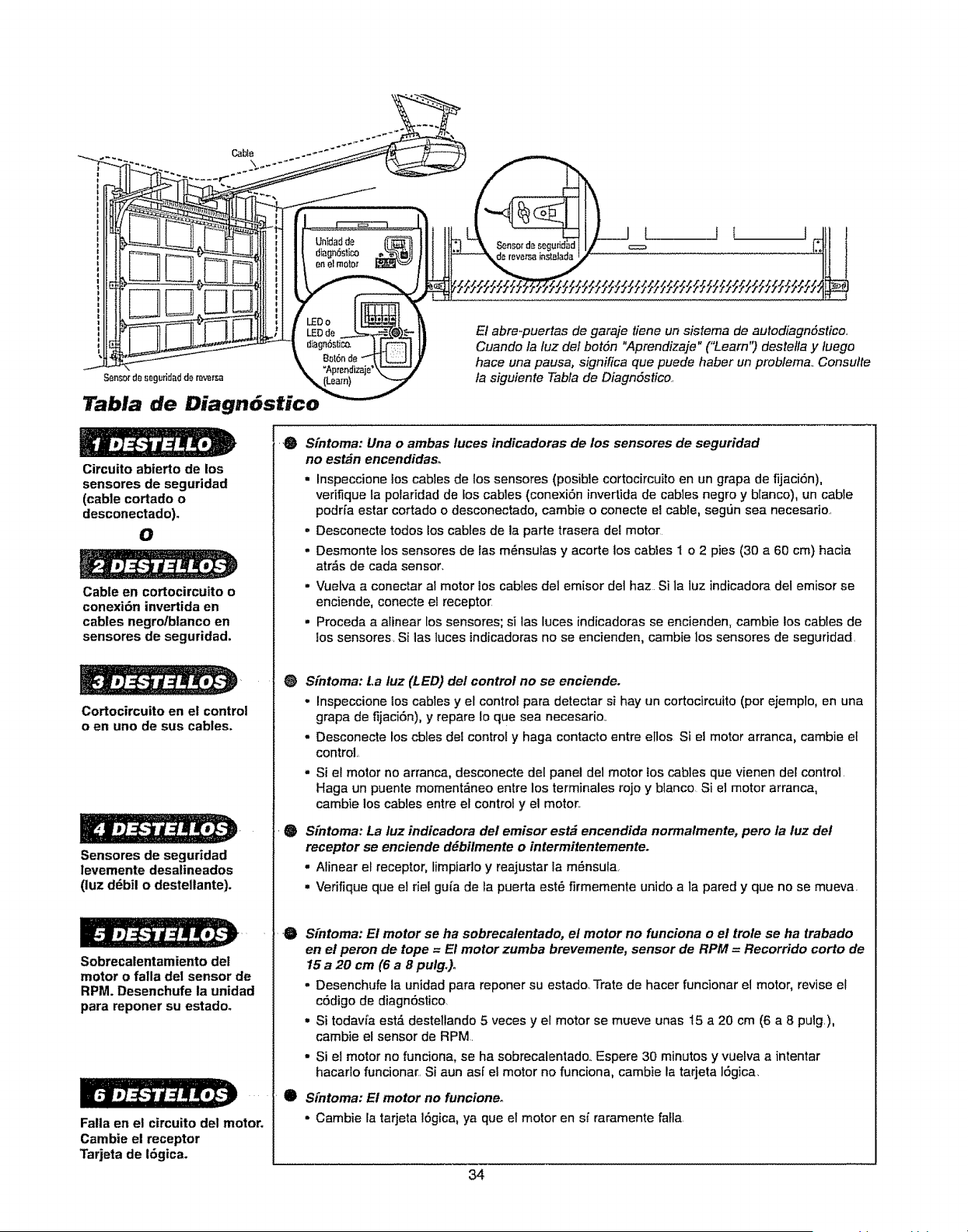
El abre-puertas de garaje tiene un sistema de autodiagnSstico.
Cuando la tuz del botSn "Aprendizaje" ("Learn") destefla y tuego
hace una pausa, significa que puede haber un problema.. Consutte
fa siguiente Tabta de DiagnSstico.
Circuito abierto de los
sensores de seguridad
(cable cortado o
desconectado).
O
Cable en cortocircuito o
conexi6n invertida en
cables negro/blanco en
sensores de seguridad.
Cortocircuito en el control
o en uno de sus cables.
Sensores de seguridad
levemente desalineados
(luz d6bil o destellante).
Sobrecatentamiento del
motor o falla del sensor de
RPM. Desenchufe la unidad
para reponer su estado.
Falla en el circuito del motor.
Cambie el receptor
Tarjeta de 16gica.
0
S[ntoma: Una o ambas luces indicadoras de los sensores de seguridad
no est_n encendidaso
• Inspeccione los cables de los sensores (posible cortocircuito en un grapa de fijaci6n),
vedfique ta polaridad de los cables (conexi6n invertida de cables negro y btanco), un cable
podrfa estar cortado o desconectado, cambie o conecte el cabre, segt_n sea necesario
= Desconecte todos los cables de la parte trasera dei moto[
° Desmonte fos sensores de fas m_nsuras y acorte los cables I o 2 pies (30 a 60 cm) hacia
atr_s de cada sensor.
° Vuetva a conectar al motor los cables del emisor del haz Si la luz indicadora del emisor se
enciende, conecte el receptor
° Proceda a alinear los sensores; si las tuces indicadoras se encienden, cambie los cables de
los sensores. S{ las luces indicadoras no se encienden, cambie los sensores de seguridad.
0 S[ntoma: La luz (LED) del control no se enciende.
• Inspeccione los cables y el control para detectar si hay un cortocircuito (por ejemplo, en una
grapa de fijaci6n), y repare Io que sea necesado,
. Desconecte los cbles dei control y haga contacto entre ellos Si el motor arranca, cambie el
control,,
• Si el motor no arranca, desconecte del panel del motor tos cables que vienen del control
Haga un puente momentfineo entre los terminales rojo y blanco Si el motor arranca,
cambie los cables entre el control y el motor..
$[ntoma: La luz indicadora del emisor est# encendida normatmente, pero la luz del
receptor se enciende d#bilmente o intermitentemente.
. Atinear el receptor, limpiado y reajustar la m6nsula,
• Verifique que et riel gufa de la puerta este firmemente unido a la pared y que no se mueva.
.O
e
Sfntoma: E! motor se ha sobrecalentado, et motor no funciona o et trole se ha trabado
en el peron de tope = El motor zumba brevemente, sensor de RPM = Recorrido corto de
15 a 20 cm (6 a 8 pulg,)o
° Desenchufe la unidad para reporter su estado. Trate de hacer funcionar el motor, revise et
c6digo de diagn6stico
• Si todavi'a esta" destellando 5 veces y el motor se mueve unas 15 a 20 cm (6 a 8 pulg.),
cambie el sensor de RPM.
• Si el motor no funciona, se ha sobrecalentado.. Espere 30 minutos y vuelva a intentar
hacado funcionar. Si aun asf el motor no funciona, cambie la tarjeta 16gica,
Sfntoma: Et motor no funcioneo
, Cambie ta tarjeta tSgica, ya que el motor en sf raramente faFfa.
34
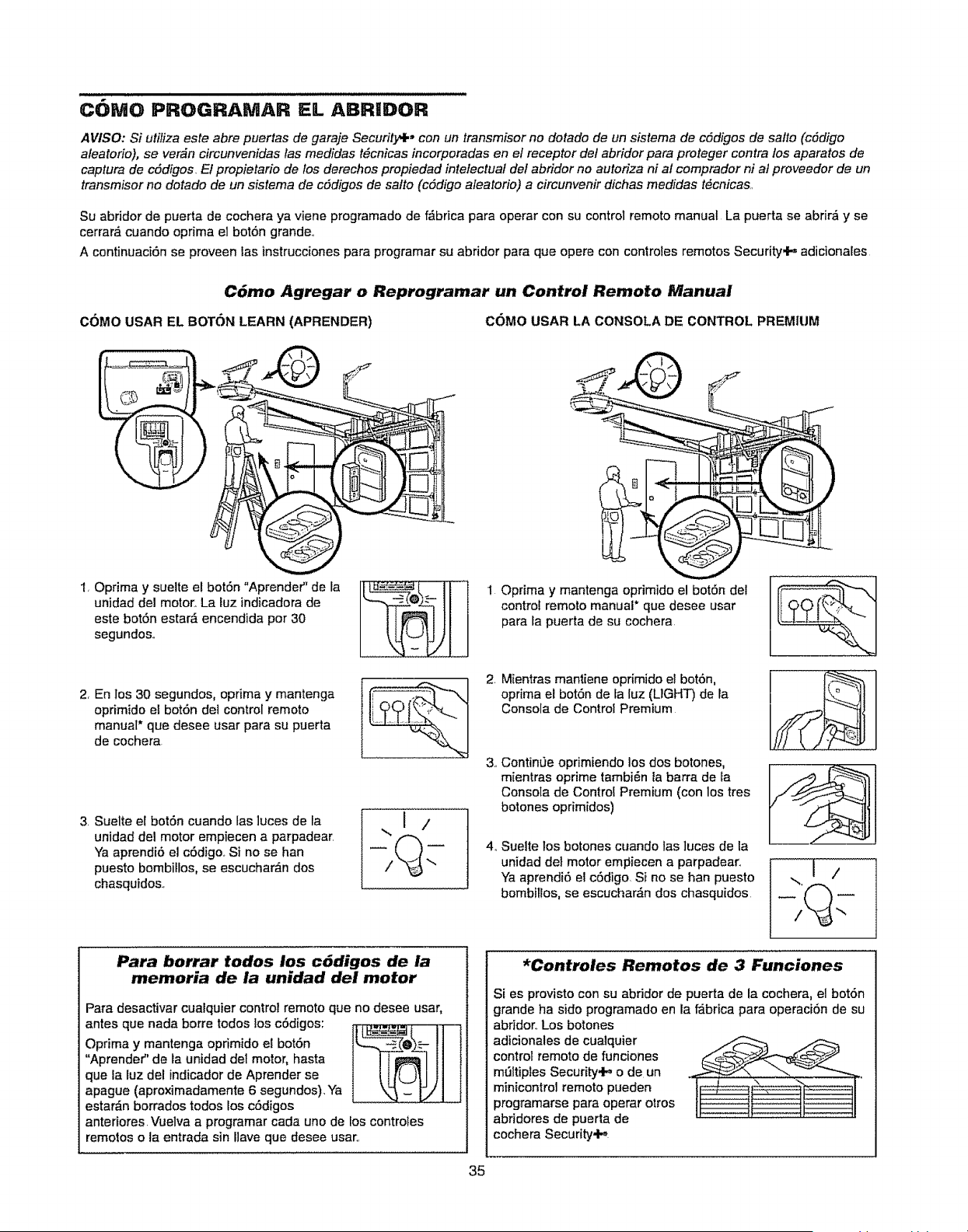
COMO PROGRAMAR EL ABRIDOR
AVISO: Si utiliza este abre puertas de garaje Security+, con un transmisor no dorado de un sistema de cddigos de safto (cSdigo
aleatorio), se ver_n circunveniclas /as medidas t_cnicas incorporadas en el receptor del abridor para proteger contra los aparatos de
captura de c6digos, El propietario de los derechos propiedad intelectuaf del abfidor no autoriza ni al comprador ni al proveedor de un
transmisor no dotado de un sistema de cddigos de salto (cddigo aleatorio) a circunvenir dichas medidas t_cnicas,,
Su abridor de puerta de cochera ya viene programado de f_brica para operar con su control remoto manual La puerta se abrir_ y se
cerrar_ cuando optima el bot6n grande.,
A continuaci6n se proveen las instrucciones para programar su abfidor para que opere con controles remotos Security.l-. adicionales
C6mo Agregar o Reprogramar un Control Remoto Manual
COMOUSAR EL BOTON LEARN(APRENDER) COMOUSAR LA CONSOLADE CONTROLPREMIUM
1, Oprima y suelte el bot6n "Aprender" de la
unidad del motor. La luz indicadora de
este bot6n estard encendida por 30
segundos,,
2, En los 30 segundos, optima y mantenga
oprimido el bot6n del control remoto
manual* que desee usar para su puerta
de cochera
3. Suelte el botSn cuando las ]uces de la
unidad del motor empiecen a parpadear,
Ya aprendi6 el c6digo,, Si no se han
puesto bombitlos, se escuchar_n dos
chasquidos,
Para borrar todos los c6digos de la
memoria de la unidad del motor
Para desactivar cualquier control remoto que no desee usar,
antes que nada borre todos los cSdigos:
__.=
Optima y mantenga oprimido el bot6n ll_-.._@_ _ I] {
**Aprender" de la unidad del motor, hasta
que la luz del indicador de Aprender se
apague (aproximadamente 6 segundos). Ya
estar_.n borrados todos los cOdigos
anteriores. Vuelva a programar cada uno de los controles
remotos o la entrada sin ,ave que desee usar..
1 Optima y mantenga oprimido el botSn del
control remoto manual* que desee usar
para fa puerta de su cochera
2. Mientras mantiene oprimido el botSn,
oprima el bot6n de fa luz (LIGHT) de la
Consola de Control Premium
3,, Contin'Je oprimiendo los dos botones,
mientras oprime tambi6n la barra de fa
Consota de Control Premium (con los tres
botones oprimidos)
4_ Sue]te los botones cuando las ]uces de la
unidad del motor empiecen a parpadear.1
Ya aprendi6 el c6digo Si no se ban puesto
bombitlos, se escuchar&n dos chasquidos
)
*Controles Remotos de 3 Funciones
Si es provisto con su abridor de puerta de la cochera, el bot6n
grande ha sido programado en la f_brica para operaciOn de su
abridor.. Los botones
adicionales de cualquier
controlremoto de funciones
mtJltiples Security.P, o de un
minicontrol remoto pueden
programarse para operar otros
abridores de puerta de
cochera Security,l._,
35
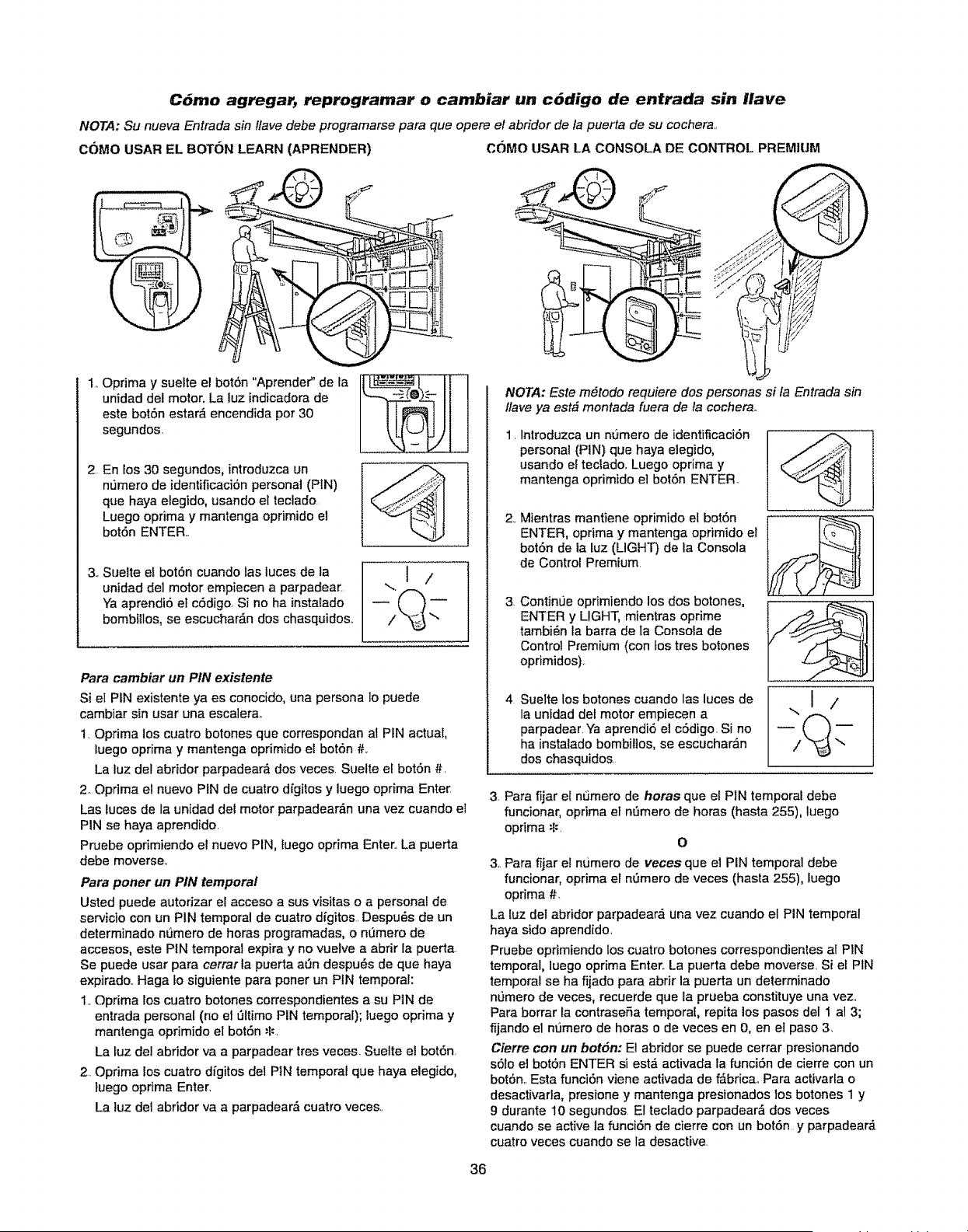
C6mo agregar, reprograrnar o cambiar un c_digo de entrada sin Ilave
NOTA: Su nueva Entrada sin ffave debe programarse para que opere el abridor de fa puerta de su cochera..
COMO USAR EL BOTON LEARN (APRENDER) COMO USAR LA CONSOLA DE CONTROL PREMIUM
1..Oprima y suette el botdn "Aprender" de la
unidad del motor. La luz indicadora de
este bot6n estar_ encendida por 30
segundos.
2 En los 30 segundos, introduzca un
nt]mero de identificaci6n personal (PIN)
que haya elegido, usando el tectado
Luego oprima y mantenga oprimido el
botdn ENTER..
3.. Sueite el botSn cuando fas luces de la
unidad del motor empiecen a parpadear.
Ya aprendi5 el c5digo. Si no ha instalado
bombillos, se escuchar&n dos chasquidos..
Para cambiar un PIN existente
Si el PIN existente ya es conocido, una persona 1o puede
cambiar sin usar una escalera_
10prima los cuatro botches que correspondan al PIN actual,
luego oprima y mantenga oprimido el bot6n #.
La luz del abridor parpadear_ dos veces. Suelte el bot6n #.
2. Oprima el nuevo PIN de cuatro d_gitos y luego oprima Enter
Las luces de la unidad del motor parpadear,_n una vez cuando el
PIN se haya aprendido.
Pruebe opdmiendo el nuevo PIN, luego oprima Enter.. La puerta
debe moverse..
Para porter un PIN temporal
Usted puede autorizar el acceso a sus visitas o a personal de
servicio con un PIN temporal de cuatro digitos. Despu_s de un
determinado n6mero de horas programadas, o nOmero de
accesos, este PIN temporal expira y no vuelve a abrir la puerta.
Se puede usar para cerrar la puerta aOn despu6s de que haya
expirado.. Haga Io siguiente para poner un PIN temporal:
1..Oprima los cuatro botones correspondientes a su PiN de
entrada personal (no el t_ttimo PIN temporal); luego oprima y
mantenga oprimido el bot6n _.
La luz del abridor va a parpadear tres veces. Suelte el bot6n.
2. Oprima los cuatro dfgitos del PiN temporal que haya elegido,
luego opdma Enter.
La luz del abridor va a parpadear,_ cuatro veces..
36
NOTA: Este m#todo requiere dos personas si fa Entrada sin
ffave ya est# montada fuera de ta cocherao
1.
2,,
3,
4
Introduzca un numero de identificaci6n
personal (PIN) que haya elegido,
usando ei teclado. Luego oprima y
mantenga oprimido el botSn ENTER.
Mientras mantiene oprimido et bot6n
ENTER, oprima y mantenga oprimido el
bot6n de ia Euz(LIGHT) de la Consola
de Control Premium
ContinLie oprimiendo los dos botones,
ENTER y LIGHT, mientras oprime
tambi6n la barra de la Consota de
Control Premium (con Lostres botones
oprimidos)_
Suelte los botones cuando las luces de
la unidad det motor empiecen a
parpadear, Ya aprendi6 el cSdigo, Si no
ha instalado bombillos, se escuchar_n
dos chasquidos
..,I /
3. Para fiiar el n_mero de horas que el PiN temporat debe
func_onar, optima et n,3mero de horas (hasta 255), luego
opdma =f_.
O
3. Para fijar el numero de veces que el PiN temporal debe
funcionar, oprima er n_mero de veces (hasta 255), Iuego
oprima #.
La luz del abddor parpadeard una vez cuando el PIN temporal
haya sido aprendido.
Pruebe oprimiendo los cuatro botches correspondientes al PIN
temporal, luego oprima Enter. La puerta debe moverse. Si et PIN
temporal se ha fijado para abrir la puerta un determinado
n_mero de veces, recuerde que Eaprueba constituye una vez_
Para borrar la contrasefia temporaE, repita los pasos del 1 al 3;
fijando el numero de horas o de veces en 0, en el paso 3.
Cierre con un botSn: E1abridor se puede cerrar presionando
s6ro el botSn ENTER si est_ activada la funciSn de cierre con un
bot6n..Esta funciSn viene activada de f_bricao Para activarla o
desactivarta, presione y mantenga presionados los botones 1 y
9 durante 10 segundos El teclado parpadear_ dos veces
cuando se active ta funciSn de cierre con un botSn y parpadear_
cuatro veces cuando se la desactive.
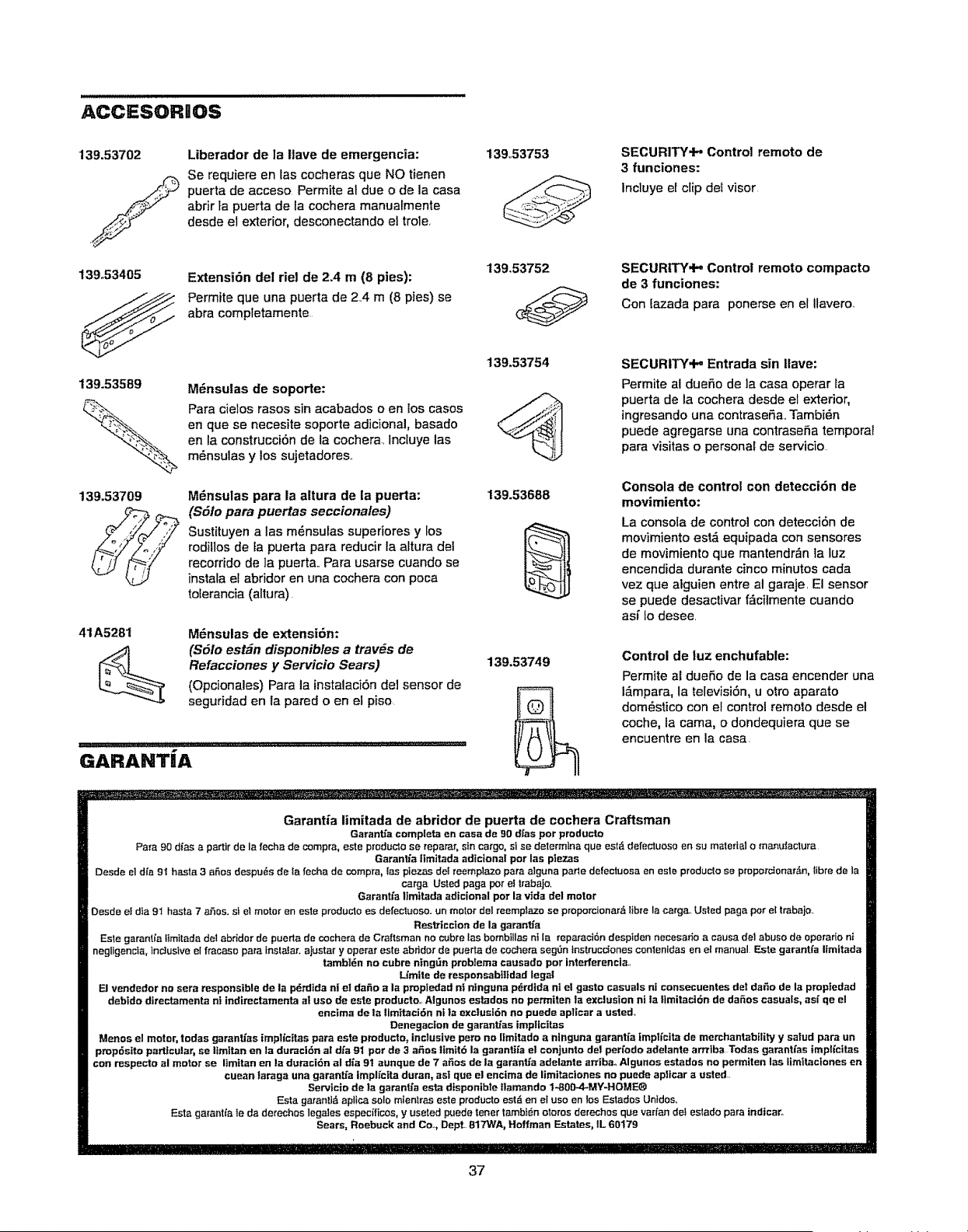
ACCESORIOS
139.53702
./
139.53405
Liberador de la Ilave de emergencia:
Se requiere en las cocheras que NO tienen
puerta de acceso Permite al due o de la casa
abrir fa puerta de la cochera manualmente
desde el exterior, desconectando el trole,
Extensi6n del riel de 2.4 m (8 pies):
Permite que una puerta de 2.4 m (8 pies) se
abra completamente
13953753
139,53752
SECURITY@" Control remote de
3 funciones:
lncluye el clip de_ visor
SECURITY,iP, Control remote compacto
de 3 funciones:
Con iazada para ponerse en el Ilavero,
139.53589
139.53709
41 A5281
Mdnsulas de soporte:
Para cielos rases sin acabados o en los cases
en que se necesite soporte adicional, basado
en la construcci6n de la cochera, Incluye las
m6nsulas y los sujetadores,.
M_nsulas para la altura de la puerta:
($61o para puertas seccionales)
Sustituyen alas m6nsulas superiores y los
rodillosde la puerta pare reducirla a_tura del
recorrido de la puerta.. Para usarse cuando se
instata et abridor en una cochera con poca
tolerancia (altura).
Mdnsulas de extensi6n:
(S51o est_n disponibles a tray,s de
Refacciones y Se-rvicio Sears)
(Opcionales) Para la instalaci6n de1sensor de
seguridad en la pared o en et piso
GARANTiA
139,53754
139.53688
139.53749
SECURITY.t- Entrada sin Ilave:
Permite al duer3o de ]a casa operar la
puerta de la cochera desde el exterior,
ingresando una contrase5a, Tambi6n
puede agregarse una contraseSa temporal
para visitas o personal de servicio
Consola de control con detecci6n de
movimiento:
La consola de control con detecci6n de
movimiento est_ equipada con sensores
de movimiento que mantendr6n la luz
encendida durante cinco minutes cada
vez que alguien entre al garaje, El sensor
se puede desactivar f_cilmente cuando
as( Io desee.
Control de luz enchufable:
Permite aEdueSo de la casa encender una
t_mpara, la televisi6n, u otto aparato
dom6stico con el control remote desde el
cache, la cama, o dondequiera que se
encuentre en la casa.
Garantia limitada de abridor de puerta de cochera Craftsman
GaranUa complete encasa de 90 dfas par producto
Papa 90 d_asa partir de la fecha de compra, este producto so reparar, sin cargo, si se determlna qua est_ defectuoso en su material o manutactura
Garan_a ilrottada adtcional par las plezas
Desde el di'a 94 haste 3 a6os despu6s do ia fecha de compra, Easpiezas de_ reeroplazo pare alguna parle detectuosa en este pmducto se proporctonar,_n,libre de la
carga Usted page par el Irabajo,
Garantfa liroitada adicional par la v_da del motor
Desde el dfa 91 basra 7 aSos. si E1motor en este producto es dofectuoso, un motor del reemp_azo se prooporoionar6Iibro la carg_L Usted paga per e[ trabajo.
Res_iccton de la garant;a
Esle garant_a llmttada dotabrider de puorta de coche_a do Craftsman no cubre las bomblllas nt la reparaci6n desplden necesario a causa dot abuse de operado ni
negligencla, inclusive el fracaso para instalar, ajusta_-y operar este abridor de puerta do cechora seg,3n instrucciones conlenidas en el roanual Este garantfa lirottada
tambi_n no cubre ning_n probleroa causada par Interferencla,,
L_roite do responsabilidad legal
El vendedor no sere responsible de la p_rdida ni el dafio a la pmpiedad of ntnguna pdrdida nl et gasto casuals ni consecuentes deI dafio de la propiedad
debido dtrectaroenta nt indirec_roenta ol usa de este producto, Algunos estados no petmiten ta exclusion ni ta llmitaci6n de daSos casuals, as{ qe el
encima de la llmttaci6n nila exctusi6n no puede aplicar a usted,
Denegacion de garanb'as imp|lcitas
Menus el motor, todas garantfas implfc|tas pare este producto, inclusive peru no llrottado a ninguna garant[a implfcita de merchantability y satud pare un
prop6s|to porticular_ se ltroitan en la duraci6n a! d/a 91 par de 3 aSes ltroit6 la garantifa el conjunto dot peri'odo adelante arrrlba Todas garant/as iropl[citas
con respecto al motor se liroitan en la dur'aci6n al dla 91 aunque de 7 a_os de la garanffa adelante arriba, Algunos estados no perroiten las liroltaciones en
cuean laraga una garantfa iropli'cita duran, asl que el enctroa de liroitaciones no puede aplicar a usted
Servicio de la garan_a esta disponible tlaroando 1-800-4-MY-HOME®
Esta garanll_, apllca solo miontras esto producto est6 en el use en los Estados Untdos.
Esta garantfa le da derechos leg=des especfficos, y useted puede tenor tambt6n otoros derechos que varfan del estado para indicar,.
Sears, Roebuck and Co_, Dept 817WA, Hoffroan Estates, IL 60179
37
Your Home
For repair-in your home-of all major brand appliances,
lawn and garden equipment, or heating and cooling systems,
no matter who made it, no matter who sold it!
For the replacement parts, accessories and
owner's manuals that you need to do-it-yourself.
For Sears professional installation of home appliances
and items like garage door openers and water heaters.
1-800-4-MY-HOME ® (1-800-469-4663)
Call anytime, day or night (U.S.A, and Canada)
www.sears.com www.sears.ca
Our Home
For repair of carry-in items like vacuums, lawn equipment,
and electronics, call or go on-line for the location of your nearest
Sears Parts & Repair Center.
1-800-488-1222
Call anytime, day or night (U.S,A, only)
www.sears.com
To purchase a protection agreement (U.S.A.)
or maintenance agreement (Canada) on a product serviced by Sears:
1-800-827-6655 (UoS,,Ao)
1-800-361-6665 (Canada)
Para pedir servicio de reparaciSn
a domicilio, y para ordenar piezas:
1-888-SU-HOGAR sM
(1-888-784-6427)
Au Canada pour service en fran£ais:
1-800-LE-FOYER Mc
(1-800-533-6937)
wwwosearsoca
114A3607B
_JMTM
® Registered Trademerk t Trademark t" Service Mark of Sears, Roebuck and Co.
® Marca Registrada / TM Marca de F_br_ca / ',_ Marca de Servicio de Sears, Roebuck and Co
L-_ MD
Marque de commerce f Marque d_pos_e de Sears_ Roebuck and Co
© 2O0B Sears. Roebuck and Co