®
P250082
93157637_A
Date Purchased
Store Purchased
Model No.
Serial No.
Vendor No.
UPC
30-Year Limited Warranty
111017
Progress Lighting fan motors are warranted to the END USER to be free of electrical
and/or mechanical defects for a period of 30 (thirty) years from date of sale. Pull chain
switches, reverse switches, capacitors and metal nishes are warranted for a period of 1
year. Warping of wooden or plastic blades is not covered by this warranty.
The END USER has the option of returning the defective fan to the place of purchase during
the rst 30 days for a replacement. After 30 days, the purchaser MUST contact Progress
Lighting for repair or replacement. The END USER also bears the responsibility for all
costs in the removal, shipping and reinstallation of fans or parts for repair or replacement.
Progress Lighting will not assume liability or responsibility for damages (including
incidental or consequential) caused by improper installation or operation of the unit or
its component parts, or by the failure of supporting hardware not supplied by Progress
Lighting. This warranty is given in lieu of all other guarantees, whether expressed or
implied, and is voided in cases of abuse, misuse or improper handling, negligence,
shipping damage, unauthorized repairs (made or attempted) or unusual application.
Some states do not allow limitations on how long an implied warranty lasts or the
exclusion or limitations of incidental or consequential damages, so the above limitations
and exclusions may not apply to you. This warranty gives you specic rights and you may
have other rights which vary from state to state.
P250082
785247264353
785247264360
785247264377

1
2
3
10
11
11
12
Safety Rules
Unpacking Your Fan
Installing Your Fan
Operating Your Fan
Care of Your Fan
Troubleshooting
Specications
Table of Contents
1. To reduce the risk of electric shock, ensure electricity
has been turned off at the circuit breaker or fuse box
before beginning.
2. All wiring must be in accordance with the National
Electrical Code ANSI/NFPA 70-1999 and local electrical codes.
Electrical installation should be performed by a
qualied licensed electrician.
3. CAUTION: To reduce the risk of personal injury, use only
the screws provided with the electrical box.
4. The outlet box and support structure must be securely
mounted and capable of reliably supporting 35 lbs. (15.9
kg). Use only UL Listed outlet boxes marked “Acceptable
for Fan Support of 35 lbs. (15.9 kg) or less.”
5. The fan must be mounted with a minimum of 7 feet
clearance from the trailing edge of the blades to the oor.
6. Do not operate reversing switch while fan blades are in
motion. Fan must be turned off and blades stopped before
reversing blade direction.
7. Avoid placing objects in path of the blades.
8. To avoid personal injury or damage to the fan and other
items, be cautious when working around or
cleaning the fan.
9. Do not use water or detergents when cleaning the fan or fan
blades. A dry dust cloth or lightly dampened cloth will be
suitable for most cleaning.
10. After making electrical connections, spliced conductors
should be turned upward and pushed carefully up into
electrical box. The wires should be spread apart with the
grounded conductor and the equipment-grounding
conductor on one side of the electrical box and ungrounded
conductor on the other side of the electrical box.
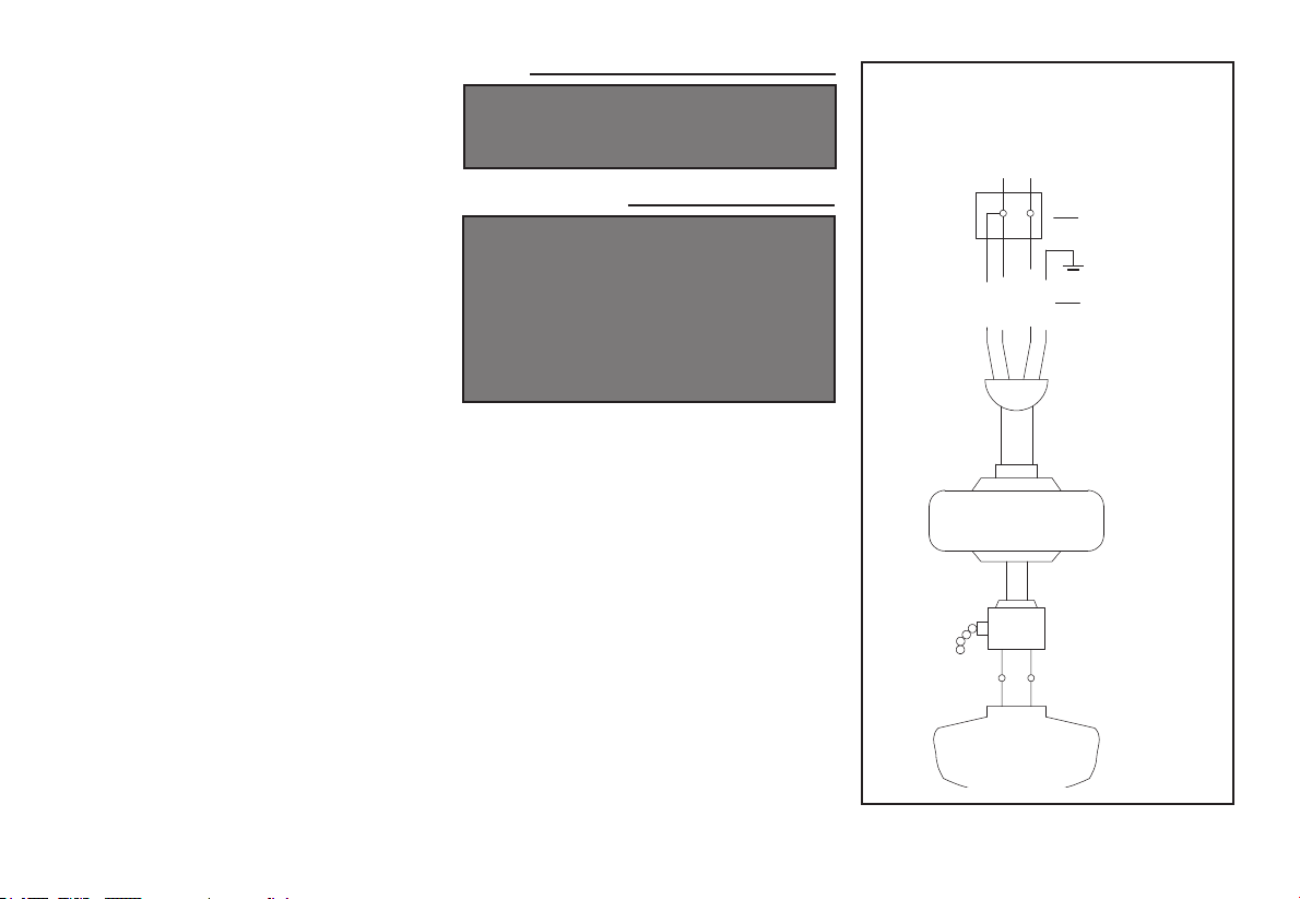
11. Electrical diagrams are for reference only. Light kits that
are not packed with the fan must be UL Listed and marked
suitable for use with the model fan you are installing.
Switches must be UL General Use Switches. Refer to the
instructions packaged with the light kits and switches for
proper assembly.
12. All set screws must be checked and retightened where
necessary before installation.
1. Safety Rules
READ AND SAVE THESE INSTRUCTIONS
TO REDUCE THE RISK OF FIRE, ELECTRIC SHOCK OR PERSONAL
INJURY, MOUNT TO OUTLET BOX MARKED “ACCEPTABLE FOR FAN
SUPPORT OF 35LBS. (15.9 KG) OR LESS”, AND USE SCREWS PRO
-
VIDED WITH THE OUTLET BOX.
TO REDUCE THE RISK OF PERSONAL INJURY, DO NOT BEND THE
BLADE BRACKETS (ALSO REFERRED TO AS (“FLANGES”) DURING
ASSEMBLY OR AFTER INSTALLATION. DO NOT INSERT OBJECTS IN
THE PATH OF THE BLADES.
TO REDUCE THE RISK OF SHOCK, THIS FAN MUST BE INSTALLED
WITH AN ISOLATION WALL CONTROL/SWITCH.
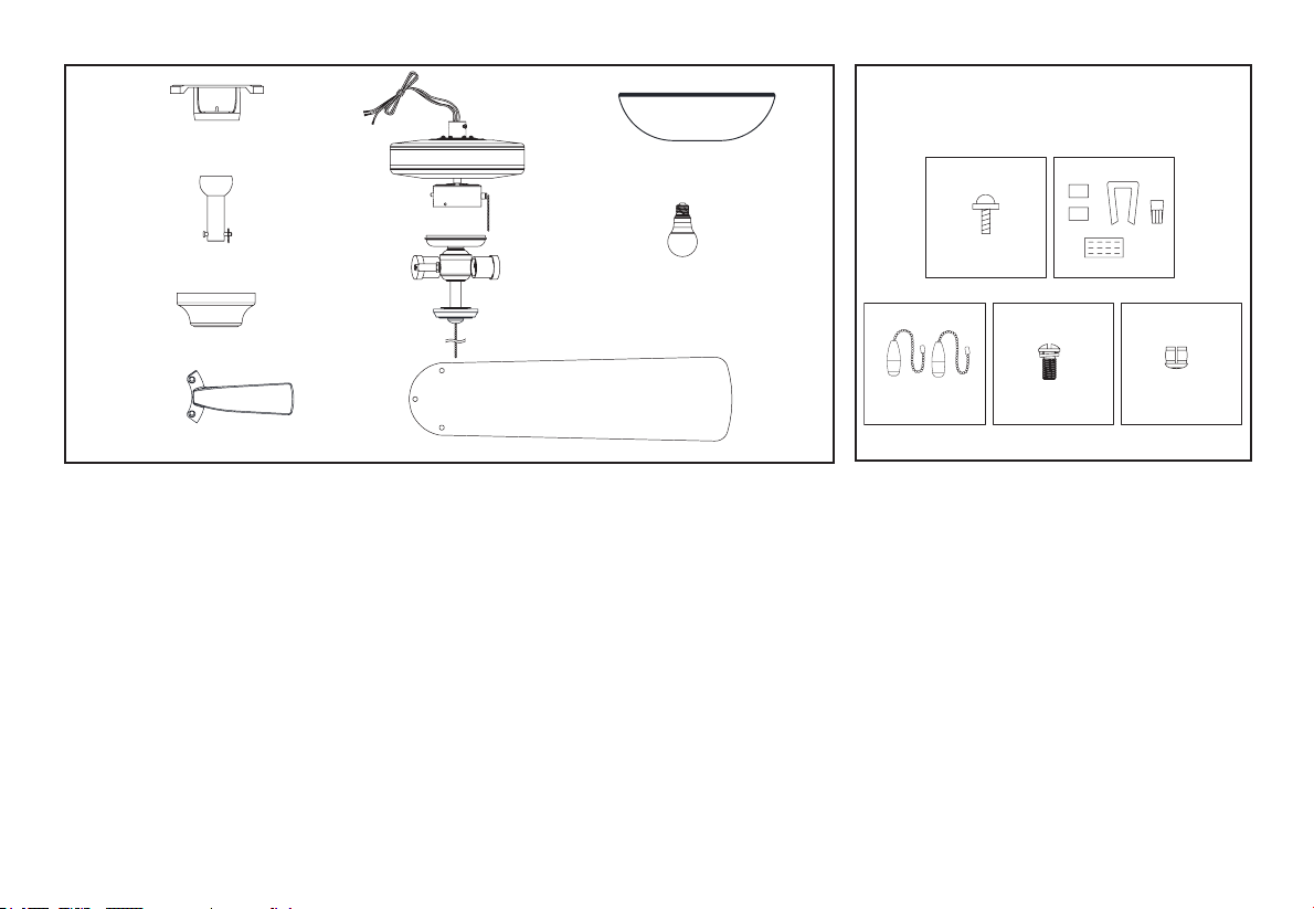
a. Mounting hardware
(16 blade attachment screws)
b. Electrical hardware & Balancing
kit (3 plastic wire connectors, blade
balancing kit)
c. Pull chain (2)
d. Extra blade bracket screw
e. Plastic plug
5. Fan Motor Assembly
6. Light Kit
7. Blades (5)
8. Shade
9. Bulbs (2)
1. Mounting Bracket (inside canopy)
2. 4.25” Ball/Downrod Assembly (hanger pin
and locking pin pre-attached)
3. Canopy
4. Blade Arms (5)
2. Unpacking Your Fan
Unpack your fan and check the contents. You should have the following items:
5
1
2
3
4
7
8
6
9
a
b
c
d e
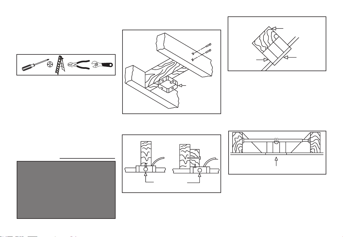
3. Installing Your Fan
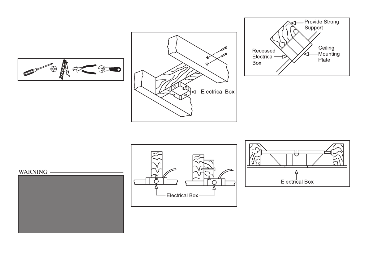
Tools Required
Phillips screw driver or straight slotted screw
driver, adjustable wrench, step ladder, and
wire cutters.
Mounting Options
If there isn’t an existing electrical box, then
read the following instructions. Disconnect
the power by removing fuses or turning off
circuit breakers.
Secure the electrical box directly to the building
structure. Use appropriate fasteners and
building materials. The electrical box and
its support must be able to fully support the
moving weight of the fan (at least 35 lbs.).
Do not use plastic electrical boxes.
Figures 1, 2, and 3 are examples of different
ways to mount the electrical box.
Note: You may need a longer downrod to
maintain proper blade clearance when
installing on a steep, sloped ceiling. The
maximum angle allowable is 30˚. If the
canopy touches downrod, remove the
decorative canopy bottom cover and turn
the canopy 180˚ before attaching the canopy
to the mounting bracket.
To hang your fan where there is an existing
xture but no ceiling joist, you may need an
installation hanger bar as shown in Figure 4.
TO REDUCE THE RISK OF FIRE, ELECTRIC
SHOCK OR PERSONAL INJURY, MOUNT
TO OUTLET BOX MARKED “ACCEPTABLE
FOR FAN SUPPORT OF 35LBS. (15.9 KG) OR
LESS”, AND USE SCREWS PROVIDED WITH
THE OUTLET BOX. ELECTRICAL BOXES
COMMONLY USED FOR THE SUPPORT OF
LIGHTING FIXTURES MAY NOT BE ACCEPT-
ABLE FOR FAN SUPPORT AND MAY NEED TO
BE REPLACED. CONSULT A QUALIFIED ELEC-
TRICIAN IF IN DOUBT.
Figure 1
Figure 2
Figure 4
Figure 3
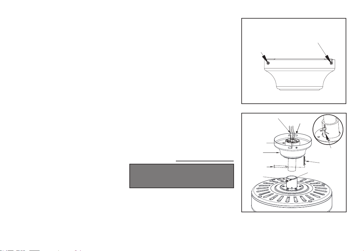
4.
Hanging the Fan
REMEMBER to turn off the power. Follow
the steps below to hang your fan properly.
NOTE: This fan is recommended for
standard ceiling mount using the downrod
provided with this fan. When using standard
ceiling installation with the 4.25 inch
downrod provided, the distance from the
ceiling to the bottom of the fan blades will be
approximately 10.4 inches.
Standard Ceiling Mounting
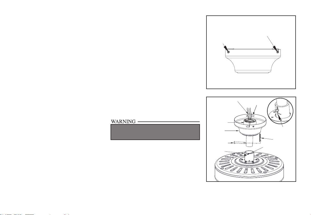
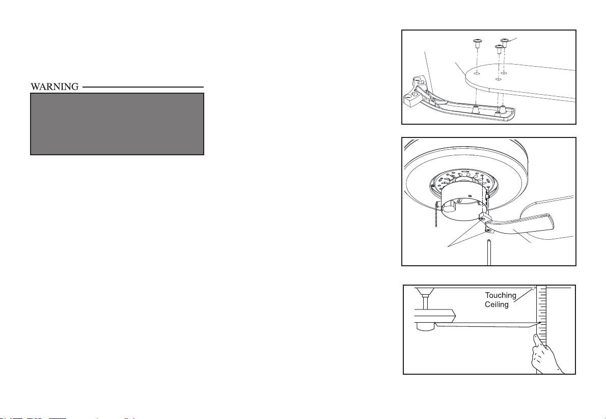
1. Remove the mounting bracket from the
canopy by loosening the four screws on
the top of the canopy. Remove the two
non-slotted screws and loosen the slotted
screws. This will enable you to remove the
mounting bracket. (Figure 5)
2. Remove the hanger pin and locking pin from
downrod assembly.
3. Make sure the slot openings are on top.
Route the wires through the canopy and then
through the ball/downrod assembly. (Figure
6)
4. Loosen, but do not remove, the set screws
on the collar on the top of the motor
housing.
Figure 6
5. Align the holes at the bottom of the downrod
with the holes in the collar on top of the
motor housing. (Figure 6)
Carefully insert the hanger pin through the
holes in the collar and downrod. Be careful
not to jam the hanger pin against the wiring
inside the downrod. Insert the locking pin
through the hole near the end of the bolt until
it snaps into its locked position, as noted in
the circle inset of Figure 6.
6. Re-tighten the set screws on the collar on top
of the motor housing.
7. Make sure that the canopy is oriented
correctly.
8. Proceed to “Installing the Fan” section.
FAILURE TO PROPERLY INSTALL SET SCREWS
AS NOTED IN STEP 6 COULD RESULT IN FAN
LOOSENING AND POSSIBLY FALLING.
Slot opening
Motor wires
Locking Pin
Tighten
screws
Hanger Pin
Canopy
Ball/Downrod
assembly
Pin in locked
position
Motor
Collar
Remove
Loosen but Do Not Remove
Figure 5
Standard Mounting
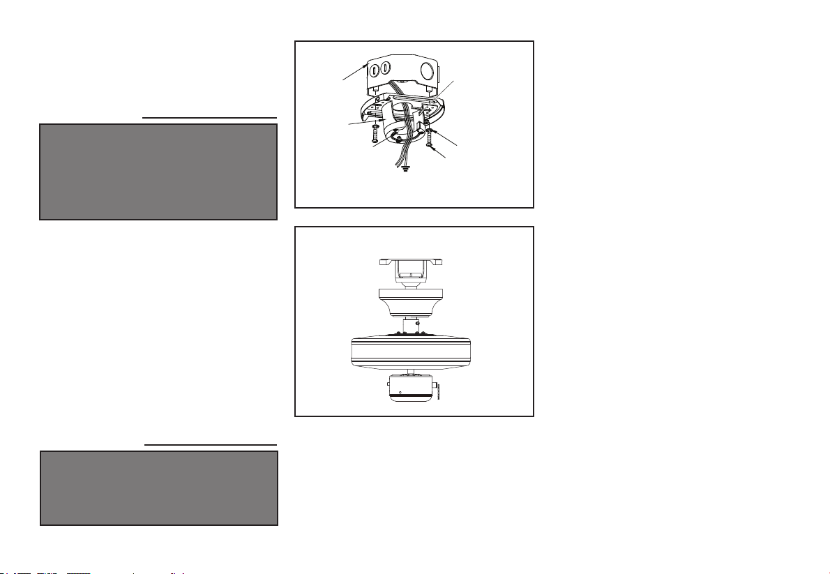
5.
Installing Fan to
the Electrical Box
WHEN MOUNTING THE FAN ON A SLOPED
CEILING, THE STANDARD BALL/DOWNROD
MOUNTING METHOD MUST BE USED. THE
MOUNTING BRACKET MUST BE MOUNTED
SO THAT THE SLOT OPENINGS ARE ON THE
LOWER SIDE BY SLIDING THE MOUNTING
BRACKET FROM THE TOP DOWN.
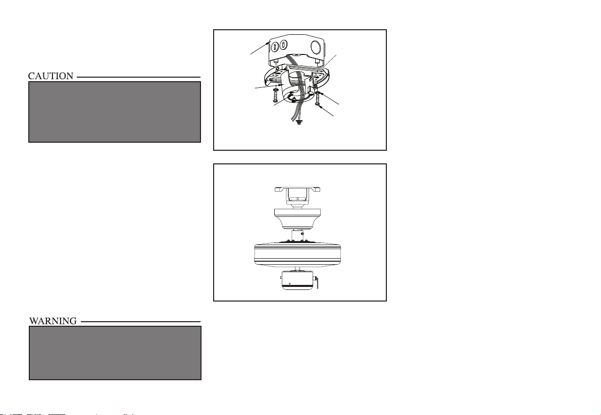
1. Pass the 120-volt supply wires through the
center hole in the ceiling mounting bracket
as shown in Figure 7.
2. Install the ceiling mounting bracket on the
electrical box by using the mounting screws
provided with the electrical box. Note that
the at side of the mounting bracket is
toward the electrical box. (Figure 7)
3. Tighten the two screws on the electrical box
securely.
4. Carefully lift the fan assembly up to the
ceiling mounting bracket. Make sure the tab
on the mounting bracket is properly seated
in the groove in the hanger ball. (Figure 8)
Figure 7
Washers
120V
Wires
UL Listed
Electrical
Box
Ceiling
Mounting
Bracket
Hook
Mounting
Screws
(Supplied with
Electrical Box)
Slot opening
WHEN USING THE STANDARD BALL/DOWNROD
MOUNTING, THE TAB IN THE RING AT THE
BOTTOM OF THE MOUNTING BRACKET MUST
REST IN THE GROOVE OF THE HANGER BALL.
FAILURE TO PROPERLY SEAT THE TAB IN THE
GROOVE COULD CAUSE DAMAGE TO WIRING.
Figure 8
6.
EACH WIRE NUT (WIRE CONNECTOR) SUPPLIED
WITH THIS FAN IS DESIGNED TO ACCEPT UP TO
ONE 12 GAUGE HOUSE WIRE AND TWO WIRES
FROM THIS FAN. IF YOU HAVE LARGER THAN
12 GAUGE HOUSE WIRING OR MORE THAN
ONE HOUSE WIRE TO CONNECT TO THE FAN
WIRING, CONSULT AN ELECTRICIAN FOR THE
PROPER SIZE WIRE NUTS TO USE.
USE THE WIRE CONNECTORS SUPPLIED WITH
YOUR FAN. SECURE THE CONNECTORS WITH
ELECTRICAL TAPE AND ENSURE THERE ARE
NO LOOSE STRANDS OR CONNECTIONS
Figure 9
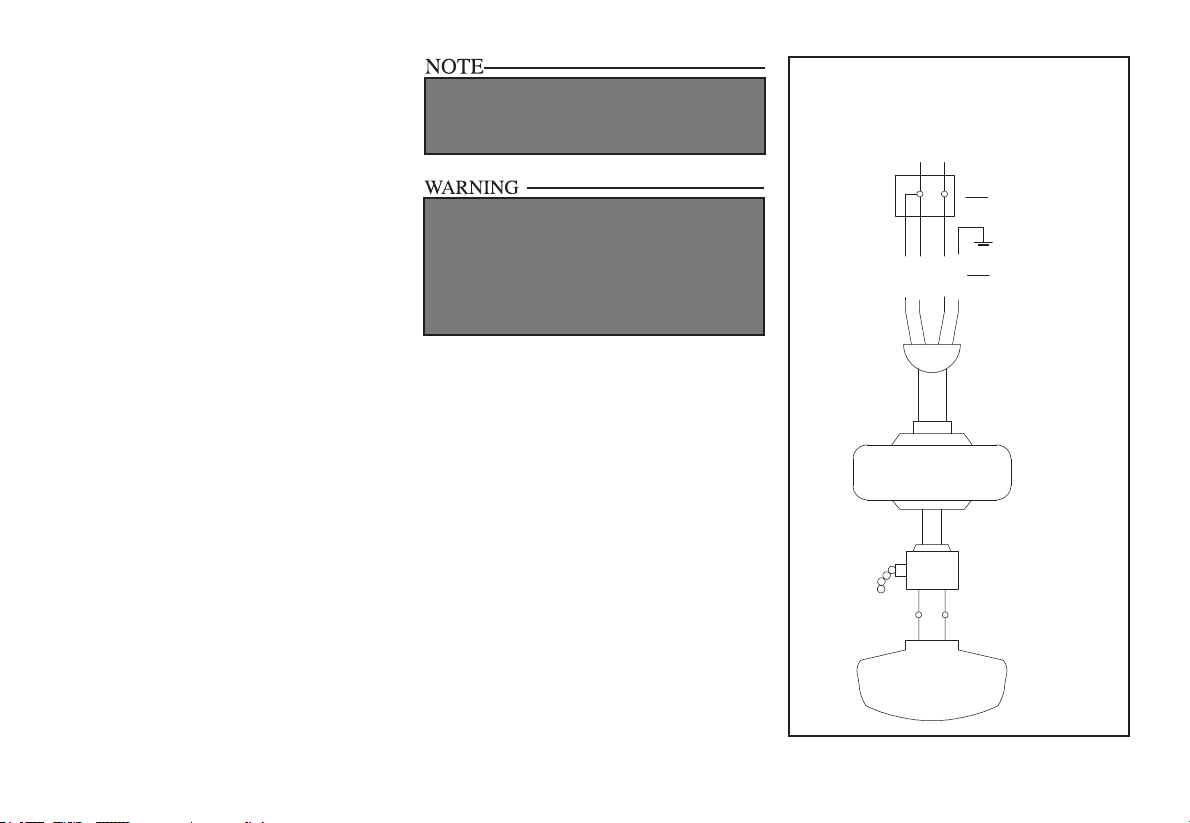
Making the Electrical
Connections
REMEMBER to disconnect the power. If
you feel you do not have enough electrical
wiring knowledge or experience, have your fan
installed by a licensed electrician.
Follow the steps below to connect the fan to
your household wiring. Use the wire
connecting nuts supplied with your fan. Secure
the connectors with electrical tape. Make sure
there are no loose strands or
connections. (Figure 9)
1. Connect the two green fan ground wires,
located on the downrod and mounting
bracket, to the household ground wire.
2. Connect the neutral fan (white) wire to the
white neutral household wire.
3. Connect the fan supply (black and blue) wire
to the black household supply wire as shown
in gure 9.
4. After connecting the wires, spread them apart
so that the green and white wires are on one
side of the outlet box and the black wire is on
the other side.
5. Turn the wire connecting nuts upward and
push the wiring into the outlet box.
SUPPLY CIRCUIT
BLACK
WHITE
WHITE
BLUE
BLACK
WHITE
BLACK
WHITE
BLUE
GREEN
Grounding
to Downrod
Outlet
box
Attaching the Fan
Blades
NOTE: Your fan blades are reversible. Select the
blade nish which best accentuates your decor.
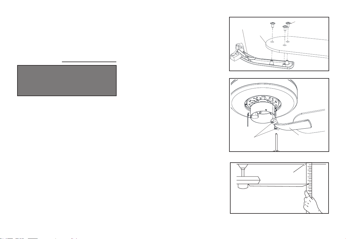
1. Attach blade to blade bracket using screws shown
in Figure 10. Repeat for the two remaining screws.
2. Tighten each screw securely.
Figure 11
Finishing the Fan
Installation
STANDARD CEILING MOUNTING
1. Align the locking slots of the ceiling canopy with
the two screws in the mounting bracket. Push up
to engage the slots and turn clockwise to lock
in place. Immediately tighten the two mounting
screws rmly.
2. Install the remaining two mounting screws into
the holes in the canopy and tighten rmly.
3. You may now proceed to attaching the fan blades.
WHEN USING THE STANDARD BALL/DOWNROD
MOUNTING, THE TAB IN THE RING AT THE
BOTTOM OF THE MOUNTING PLATE MUST
REST IN THE GROOVE OF THE HANGER BALL.
FAILURE TO PROPERLY SEAT THE TAB IN THE
GROOVE COULD CAUSE DAMAGE TO WIRING.
7.
Figure 10
Blade Balancing
All blades are grouped by weight. Because natural
woods vary in density, the fan may wobble even
though the blades are weight matched.
The following procedure should correct most fan
wobble. Check after each step.
1. Check that all blade screws are secure.
2. Most fan wobble problems are caused when blade
levels are unequal. Check this level by selecting
a point on the ceiling above the tip of one of the
blades. Measure from a point on the center of
each blade to the point on the ceiling. Measure
this distance as shown in Figure 12. Rotate the fan
until the next blade is positioned for measurement.
Repeat for each blade. Measurements deviation
should be within 1/8”. Run the fan for 10 minutes.
3. Make sure that canopy is tightened securely to
ceiling mounting bracket and that the ceiling
mounting bracket is tightened securely to the
electrical box.
4. Interchanging two adjacent blades can redistribute
the weight and possibly result in the smoother
operation.
5. Use the enclosed Blade Balancing Kit if the blade
wobble is still noticeable.
3. Fasten the blade assembly to the motor by
aligning the screw holes on the bottom of the
fan motor with the holes on the blade arm,and
tightening the motor screws. Please note that
the motor screws are pre-attached into the blade
brackets. (Figure 11)
4. Repeat steps 1,2 & 3 for the remaining blades.
Figure 12
Screws Blade Arm
Blade
Blade Arm
Screws
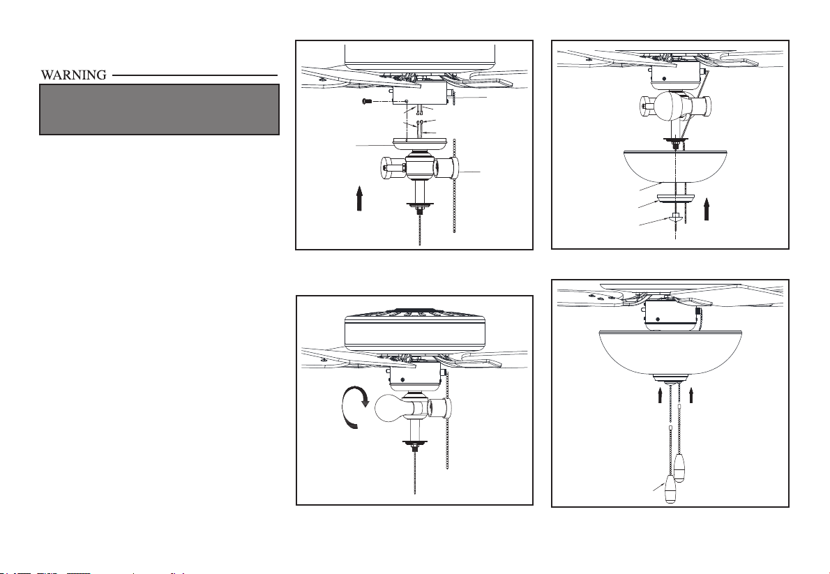
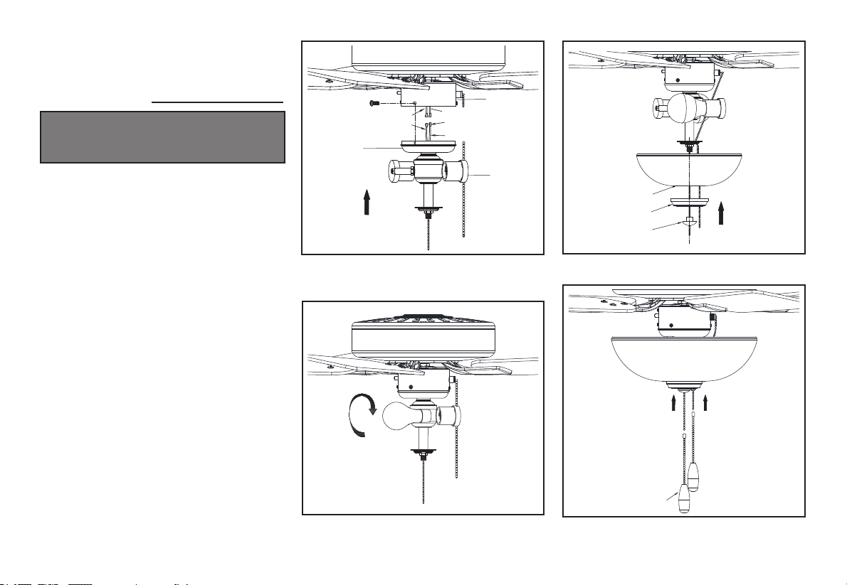
Installing the Light Kit
1. Remove and retain the three mounting screws
from the switch housing cover of the light kit tter
assembly (Figure 13).
2. Connect the wires from the switch housing to
the wires from the light kit tter by connecting
the molded adaptor plugs together (blue to black,
white to white).
3. Carefully tuck all the wires and splices into the
switch housing.
4. Attach the switch housing cover with light kit
tter to the switch housing using the three screws
that were previously removed in step 1.
5. Install the two LED lamps (provided) into the
light kit tter sockets (Figure 14).
6. Pass the fan switch chain through the slot cut-off
in the bowl cap (Figure 15).
7. Position the glass bowl over the threaded nipple
and seat the bowl on bowl cap. Pass the fan pull
chain through the bushing in the outer bowl cap
and install the outer bowl cap on the threaded
nipple. Install and nger tighten the nial (Figure
15).
8. Install the pull chain extension chains and fobs
(Figure 16).
TO REDUCE THE RISK OF ELECTRIC SHOCK,
DISCONNECT THE ELECTRICAL SUPPLY
CIRCUIT TO THE FAN BEFORE INSTALLING
THE LIGHT FIXTURE.
Figure 13
Figure 14
Figure 15
Figure 16
8.
Black
Blue
Molded adaptor plugs
White
White
Switch
housing
Switch
housing
cover
Light kit
fitter
assembly
Outer bowl cap
Finial
Shade
Fob
pendant

Fob
Reverse
switch
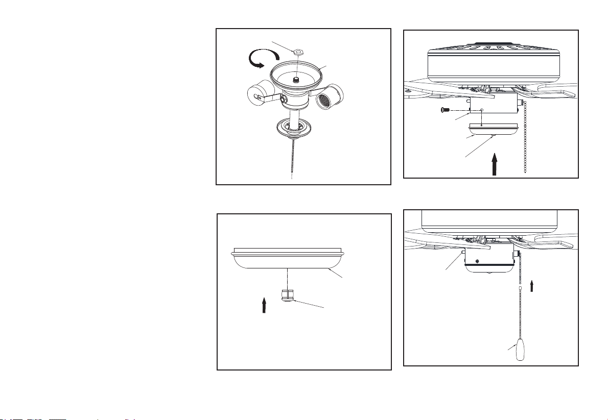
9.
Assembling the Fan
without the Light Kit
1. In order to use the fan without the light kit,
remove the switch housing from the top of light
kit tter assembly by removing the center hex
nut inside the switch housing, and then thread the
switch housing cover off the threaded nipple on
the top of the light kit tter assembly (gure 17).
2. Press the plastic plug (provided) into the center
hole of the switch housing (gure 18).
3. Remove and retain the three mounting screws
from the switch housing cover of the light kit
tter assembly (Figure 13).
4. Position the switch housing cover onto the switch
housing and reinstall the light kit mounting
screws (gure 19).
5. Install the pull chain extension chain and fob
(Figure 20).
Figure 19
Figure 20
Switch housing
Switch housing
cover
Plug
Figure 17
Figure 18
Switch housing
cover
Hex nut
Switch housing
cover
Plug
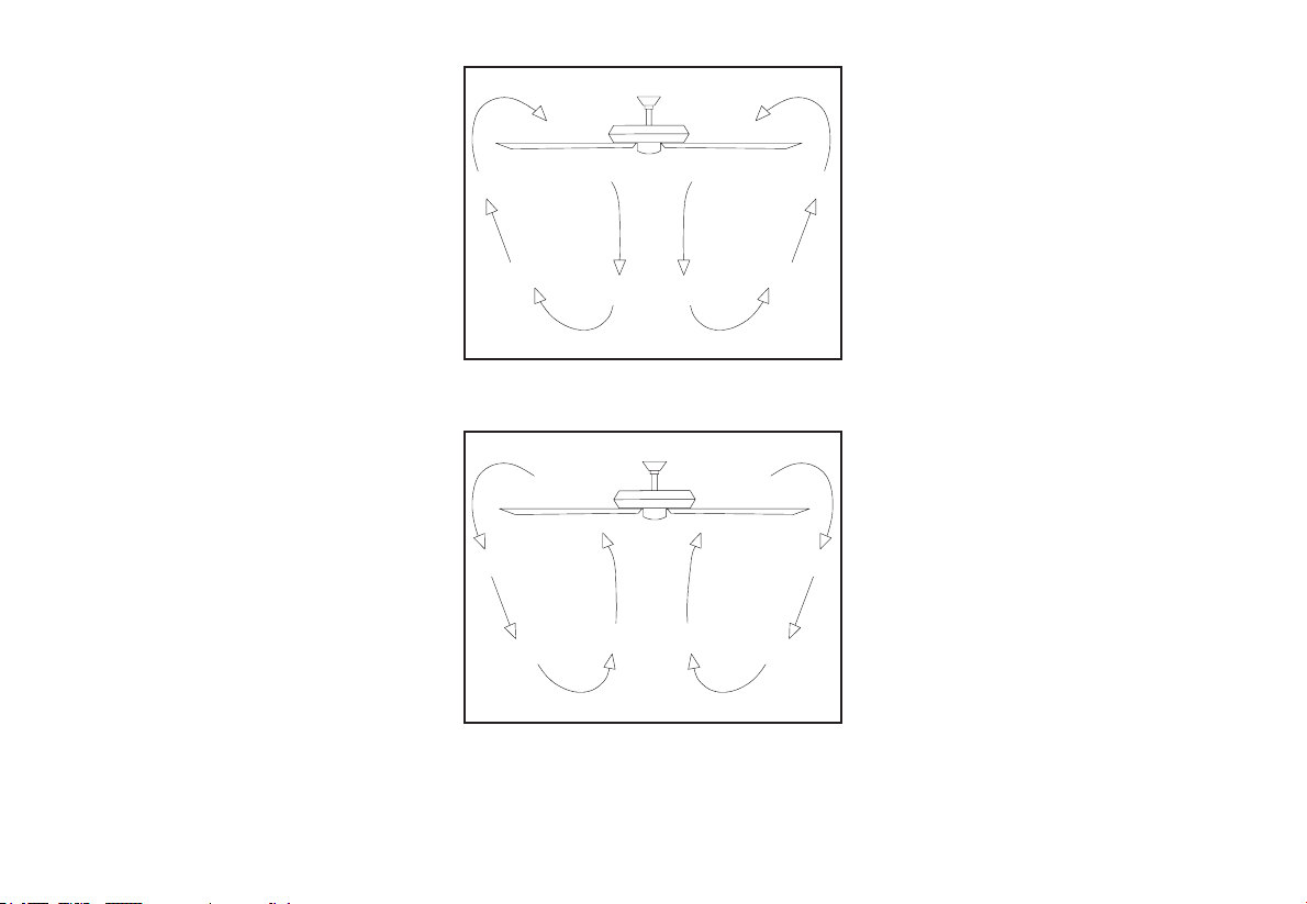
Speed settings for warm or cool weather
depend on factors such as room size, ceiling
height, number of fans, and so on.
The fan shipped from the factory with the
reverse switch positioned to circulate air
downward. If airow is desired in the opposite
direction, turn your fan off and wait for the
blades to stop turning, then slide the reverse
switch (located on the switch housing, refer to
gure 20) to opposite position, and turn fan on
again. The fan blades will turn in the opposite
direction and reverse airow.
Figure 21
Figure 22
Warm weather - (Forward) A downward
air ow creates a cooling effect as shown
in Figure 21. This allows you to set your
air conditioner on a higher setting without
affecting your comfort.
Cool weather - (Reverse) An upward air ow
moves warm air off the ceiling are as shown in
Figure 22. This allows you to set your heating
unit on a lower setting without affecting your
comfort.
10. Operating Your Fan

11. Care of Your Fan and Troubleshooting
Care of Your Fan
Here are some suggestions to help you
maintain your fan.
1. Because of the fan’s natural movement,
some connections may become loose.
Check the support connections, brackets,
and blade attachments twice a year. Make
sure they are secure. (It is not necessary to
remove fan from ceiling.)
2. Clean your fan periodically to help maintain
its new appearance over the years. Do not
use water when cleaning, this could damage
the motor, or the wood or possibly cause
an electrical shock. Use only a soft brush
or lint-free cloth to avoid scratching the
nish. The plating is sealed with a lacquer to
minimize discoloration or tarnishing.
Warning - Make sure the power is off
before cleaning your fan.
3. You can apply a light coat of furniture polish
to the wood for additional protection and
enhanced beauty. Cover small scratches with
a light application of shoe polish.
4. There is no need to oil your fan.
The motor has permanently lubricated sealed
ball bearings.
MAKE SURE THE POWER IS OFF AT THE ELECTRICAL PANEL BOX
BEFORE YOU ATTEMPT TO MAKE ANY REPAIRS. REFER TO THE SECTION,
“MAKING ELECTRICAL CONNECTIONS.”
Fan will not start
Fan sounds noisy
1. Check main and branch circuit fuses or breakers
2. Check line wire connections to the fan and switch wire connections in
the switch housing. CAUTION: Make sure main power is off.
1. Make sure all motor housing screws are snug.
2. Make sure the screws that attach the fan blade bracket to the motor hub
are tight.
3. Make sure wire nut connections are not rattling against each other or
the interior wall of the switch housing.
CAUTION: Make sure power is off.
4. Allow a 24-hour “breaking in” period. Most noises associated with a
new fan disappear during this time.
5. If using the Ceiling Fan light kit, make sure the screws securing the
glassware are tight. Check that the light bulb is also secure.
6. Make sure the canopy is a short distance from the ceiling.
It should not touch the ceiling.
7. Make sure your electrical box is secure and rubber isolator pads were
used between the mounting bracket and electrical box.
Troubleshooting
Problem Solution

12. Specications
FAN
SIZE
SPEED VOLTS
FAN POWER
CONSUMPTION
(WITHOUT LIGHTS)
WATTS
AIRFLOW
CFM
AIRFLOW
EFFICIENCY
(HIGHER IS BETTER)
CFM/WATT
NET
WEIGHT
GROSS
WEIGHT
CUBE
FEET
52”
Low 120
15.43
Lbs
18.08
Lbs
1.86
High 120
©2016 Progress Lighting, Inc.
701 Millennium Blvd.,
Greenville, SC 29607
All Rights Reserved
11.93 2078 174.18
45.14 4358 96.54
®
Manual de instalación de ventilador de techo
P250082
93157637_A

Fecha de compra
Tienda donde se compró
Modelo núm.
Número de serie
Proveedor Nº.
UPC
30 años de garantía limitada
111017
Los motores de ventilador Progress Lighting están garantizados al USUARIO FINAL
por treinta (30) años, a partir de la fecha de compra, de que estarán libres de defectos
eléctricos o mecánicos. Los interruptores activados por cadena, interruptores de reversa,
capacitores y acabados de metal tienen 1 año de garantía. No están cubiertas por esta
garantía las deformaciones de las aspas de madera o plástico.
El USUARIO FINAL tiene la opción de devolver el ventilador defectuoso adonde lo
compró, dentro de los 30 días siguientes a la compra, al efecto de su reposición. Pasados
esos 30 días, el comprador TIENE que contactar a Progress Lighting para reparación
o reposición. El USUARIO FINAL es responsable de todos los costos por desmontaje,
envío y reinstalación del ventilador, así como de las partes y piezas a reparar o reponer.
Progress Lighting no asumirá responsabilidad alguna por daños (incluso incidentales
o consecuentes) causados por instalación o manipulación inapropiadas de la unidad
o sus partes y piezas componentes, ni por fallas de herrajes de soporte que no fueron
suministrados por Progress Lighting. Esta garantía se concede en sustitución de todas las
demás, ya sean explícitas o implícitas, y se anulará en caso de uso abusivo o aplicación
inusual, mal uso o mala manipulación, negligencia, daños en el envío y reparaciones no
autorizadas (consumadas o intentadas).
Algunos estados no permiten limitaciones en la duración de una garantía implícita ni
exclusión ni limitaciones de daños incidentales o consecuentes, así que las exclusiones o
limitaciones referidas más arriba pudieran no aplicarse a su caso. Esta garantía le otorga
derechos especícos y es posible que usted tenga otros, que varían de estado a estado.
P250082
785247264353
785247264360
785247264377
1
2
3
10
11
11
12
Normas de seguridad
Cómo desempacar el ventilador
Cómo instalar el ventilador
Cómo usar el ventilador
Cuidado del ventilador
Solución de problemas
Especicaciones
Tabla de contenido

1. Para disminuir el riesgo de descarga eléctrica, antes de comenzar
la instalación asegúrate de que la electricidad ha sido cortada en
el cortacircuitos o en la caja de fusibles.
2. Todo el cableado tiene que cumplir con el Código Nacional de
Electricidad ANSI/NFPA 70-1999 y los códigos eléctricos locales. La
instalación eléctrica debe hacerse por un electricista calicado
con licencia.
3. PRECAUCIÓN: Para reducir el riesgo de lesiones físicas, usa
sólo los tornillos suministrados con la caja de distribución.
4. La caja eléctrica y estructura de soporte tienen que montarse de
forma segura para poder sostener con conanza 35 lb (15.9 kg).
Usa solo cajas eléctricas aprobadas por UL y marcadas como
“Apropiadas para sostener ventiladores de 35 lb (15.9 kg) o
menos”.
5. El ventilador tiene que montarse con al menos 7 pies (2.13 m) de
separación entre el borde trasero de las aspas y el piso.
6. No operar el interruptor de reversa mientras las aspas del
ventilador estén en movimiento. El ventilador tiene que estar
apagado y las aspas detenidas antes de invertir el sentido del
movimiento.
7. Evita colocar objetos en la trayectoria de las aspas.
8. Para evitar lesiones personales o daños al ventilador y otros
artículos, ten cuidado al limpiarlo o al trabajar cerca de él.
9. No usar agua ni detergentes para limpiar el ventilador o las
aspas. Para limpiar, casi siempre será adecuado un paño seco o
ligeramente humedecido con que quitar el polvo.
10. Después de concluir con las conexiones eléctricas, debes voltear
los conductores empalmados hacia arriba y empujarlos con
cuidado hacia dentro de la caja de distribución. Los cables deben
estar separados, con el cable y el conductor a tierra del equipo
hacia uno de los lados de la caja eléctrica y el conductor sin
conexión a tierra hacia el lado opuesto.
11. Los diagramas eléctricos son sólo para referencia. Los kits
de luces no empaquetados con el ventilador tienen que estar
aprobados por UL y marcados como apropiados para usar con
el modelo de ventilador que estás instalando. Los interruptores
tienen que estar clasicados de uso general por UL. Para
ensamblar bien, consulta las instrucciones adjuntas a los kits de
luces e interruptores.
12. Antes de la instalación, todos los tornillos de jación tienen que
comprobarse y reajustarse donde sea necesario.
1. Normas de seguridad
LEE Y GUARDA ESTAS INSTRUCCIONES
PARA REDUCIR EL RIESGO DE INCENDIO, DESCARGA ELÉCTRICA
U OTRAS LESIONES, INSTALA SÓLO EN UNA CAJA ELÉCTRICA
CLASIFICADA COMO “APROPIADA PARA SOSTENER VENTILADORES
DE 35 LB (15.9 KG) O MENOS”, Y USA SÓLO LOS TORNILLOS INCLUIDOS
CON LA CAJA ELÉCTRICA.
PARA REDUCIR EL RIESGO DE LESIONES, NO DOBLES LOS BRAZOS DE LAS
ASPAS (TAMBIÉN LLAMADOS “REBORDES”) DURANTE NI DESPUÉS DE LA
INSTALACIÓN. NO COLOCAR OBJETOS EN LA TRAYECTORIA DE LAS ASPAS.
PARA EVITAR EL RIESGO DE DESCARGA ELÉCTRICA, ESTE VENTILADOR
DEBE SER INSTALADO CON UN CONTROL/INTERRUPTOR DE AISLAMIENTO
DE MONTAJE EN PARED.
ADVERTENCIA
ADVERTENCIA
ADVERTENCIA

a. Herrajes para montaje
(16 tornillos para el montaje de aspas)
b. Herrajes eléctricos y kit de
compensación (3 conectores plásticos de
cables, kit de compensación de aspas)
c. Interruptor de cadena (2)
d. Tornillo adicional para soporte de
aspas
e. Tapón plástico
5. Conjunto del motor del ventilador
6. Carcasa del
7. Aspas (5)
8. Pantalla
9. Bombillas (2)
1. Soporte de montaje (dentro de la cubierta)
2. Conjunto de tubo bajante/bola de 4.25”
(10.8 cm) (con pasadores de soporte y de
cierre prejados)
3. Cubierta
4. Brazos de aspas (5)
2. Cómo desempacar el ventilador
Desempaca tu ventilador y revisa el contenido. Debes tener los siguientes artículos:
5
1
2
3
4
7
8
6
9
a
b
c
d e
3. Cómo instalar el ventilador
Herramientas
necesarias
Destornillador Phillips o de punta plana, llave
ajustable, escalera de tijera y cortacables.
Opciones de montaje
Si no hay una caja eléctrica presente, lee
las siguientes instrucciones. Desconecta la
energía retirando los fusibles o apagando los
cortacircuitos.
Asegura la caja eléctrica directamente a la estructura
de la edicación. Usa sujetadores y materiales de
construcción apropiados. La caja eléctrica y su
soporte tienen que poder sostener todo el peso en
movimiento del ventilador (al menos 35 lb = 15.9 kg).
No uses cajas eléctricas de plástico.
Las guras 1, 2 y 3 ejemplican diferentes mane-
ras de montar la caja eléctrica.
Caja eléctrica
Caja eléctrica
Caja
eléctrica
empotrada
Provee
un soporte
fuerte
Placa de
montaje
en techo
Nota: Tal vez necesites un tubo bajante más
largo para mantener la altura mínima adecuada
de las aspas al instalar el ventilador en un techo
inclinado. El ángulo máximo permitido es 30º.
Si la cubierta toca el tubo bajante, retira la
cubierta decorativa inferior y gira la cubierta
180º antes de jarla al soporte de montaje.
Caja eléctrica
Para colgar el ventilador donde haya una lámpara,
pero ninguna viga de techo, tal vez necesites una
barra colgante como se muestra en la Figura 4.
PARA REDUCIR EL RIESGO DE INCENDIO,
DESCARGA ELÉCTRICA U OTRAS LESIONES,
INSTALA SÓLO EN UNA CAJA ELÉCTRICA
CLASIFICADA COMO “APROPIADA PARA SOSTENER
VENTILADORES DE 35 LB (15.9 KG) O MENOS”, Y USA
SÓLO LOS TORNILLOS INCLUIDOS CON LA CAJA
ELÉCTRICA. LAS CAJAS ELÉCTRICAS UTILIZADAS
COMÚNMENTE PARA EL SOPORTE DE ARTÍCULOS
DE ILUMINACIÓN PUEDEN NO SERVIR COMO UN
SOPORTE DE VENTILADOR, Y TAL VEZ DEBAN
REEMPLAZARSE. EN CASO DE DUDA, CONSULTA A
UN ELECTRICISTA CALIFICADO.
Figura 1
Figura 2
Figura 4
Figura 3
ADVERTENCIA
4.
Cómo colgar el
ventilador
RECUERDA cortar el suministro de
electricidad. Sigue los pasos más abajo para
colgar correctamente tu ventilador.
NOTA: Se recomienda instalar este ventilador
en techo interior estándar usando el tubo bajante
incluido. Cuando uses una instalación de techo
estándar con el tubo bajante de 4.25 plg
(10.8 cm) suministrado, la distancia desde el
techo a la parte inferior de las aspas será de
unas 10.4 plg (26.4 cm).
Montaje estándar en techo
1. Retira el soporte de montaje de la cubierta
aojando los cuatro tornillos en la parte
superior de la cubierta. Quita los dos tornillos
sin ranura y aoja los tornillos ranurados.
Esto te permitirá retirar el soporte de montaje
(Figura 5)
2. Retira los pasadores de soporte y de cierre en
el conjunto del tubo bajante.
3. Asegúrate de que las ranuras queden en la
parte superior. Inserta los cables a través de la
cubierta y enseguida a través del conjunto del
tubo bajante y esfera. (Figura 6)
Figura 6
4. Aoja, sin quitarlos, los tornillos de jación en
el collarín de la parte superior de la carcasa de
motor.
5. Alinea los oricios en la parte inferior del tubo
bajante con aquellos del collarín en la parte
superior de la carcasa de motor. (Figura 6)
Inserta con cuidado el pasador de soporte a
través de los oricios del collarín y del tubo
bajante. Ten cuidado de no apretar contra
el cableado dentro del tubo bajante. Inserta
el pasador de cierre en el oricio cercano
al extremo del perno hasta que encaje en su
posición, como se muestra en el círculo de la
Figura 6.
6. Vuelve a apretar los tornillos del collarín en la
parte superior de la carcasa del motor.
7. Asegúrate de que la cubierta tenga la orientación
apropiada.
8. Pasa a la sección “Cómo instalar el ventilador”.
SI NO COLOCAS CORRECTAMENTE LOS TORNILLOS
SEGÚN LO NDICADO EN EL PASO 6, SE PUEDEN
AFLOJAR Y POSIBLEMENTE SE CAIGA EL
VENTILADOR.
Abertura
de ranura
Cables del motor
Pasador de
seguridad
Aprieta los
tornillos
Pasador de
soporte
Cubierta
Conjunto de
tubo bajante/
esfera
Pasador en
posición de cierre
Collarín
del motor
Quitar
Aflojar pero no quitar
Figura 5
ADVERTENCIA
Montaje estándar
5.
Cómo instalar el
ventilador en la caja
eléctrica
CUANDO MONTES EL VENTILADOR EN UN TECHO
INCLINADO, DEBES USAR EL MÉTODO DE MONTAJE
CON TUBO BAJANTE-ESFERA ESTÁNDAR. EL
SOPORTE DE MONTAJE TIENE QUE INSTALARSE
DE MANERA TAL QUE LAS ABERTURAS DE RANURA
QUEDEN EN EL LADO INFERIOR, DESLIZANDO EL
SOPORTE DE MONTAJE DE ARRIBA ABAJO.
1. Pasa los cables de suministro de 120 voltios
a través del oricio central en el soporte de
montaje de techo como lo muestra la Figura 7.
2. Instala el soporte de montaje de techo sobre la caja
eléctrica, usando los tornillos de montaje incluidos
con ella. Nota que el lado plano del soporte de
montaje está hacia la caja eléctrica. (Figura 7)
3. Aprieta bien los dos tornillos en la caja eléctrica.
4. Con cuidado alza el conjunto del ventilador
hasta el soporte de montaje en el techo.
Asegúrate de que la pestaña en el soporte de
montaje esté bien asentada dentro de la ranura
de la esfera de soporte. (Figura 8)
Figura 7
Arandelas
Cables de 120 V
Caja eléctrica
aprobada
por UL
Soporte
de
montaje
en cielo
raso
Gancho
Tornillos de montaje
(incluidos con la
caja eléctrica)Screws
Abertura de ranura
EN EL MONTAJE ESTÁNDAR DE TUBO BAJANTE/
ESFERA, LA PESTAÑA EN EL ARO DE LA PARTE
INFERIOR DEL SOPORTE DE MONTAJE TIENE
QUE ENCAJAR EN LA RANURA DE LA ESFERA DE
SOPORTE. SI NO ENCAJA BIEN LA PESTAÑA EN LA
RANURA PUEDE DAÑARSE EL CABLEADO.
Figura 8
ADVERTENCIA
ADVERTENCIA
6.
CADA TUERCA DEL CABLE (CONECTOR DE
CABLE) INCLUIDA CON ESTE VENTILADOR ESTÁ
DISEÑADA PARA ACEPTAR UN CABLE DOMÉSTICO
DE CALIBRE 12 COMO MÁXIMO Y DOS CABLES
DEL VENTILADOR. SI TIENES UN CABLEADO
DOMÉSTICO DE CALIBRE SUPERIOR A 12 O MÁS
DE UN CABLE DOMÉSTICO PARA CONECTAR EL
CABLEADO DEL VENTILADOR, CONSULTA A UN
ELECTRICISTA PARA EL TAMAÑO ADECUADO DE
TUERCAS DE CABLE.
USA LOS CONECTORES DE CABLE INCLUIDOS
CON TU VENTILADOR. SUJETA LOS CONECTORES
CON CINTA DE ELECTRICISTA Y ASEGURA QUE NO
HAYA CONEXIONES NI CABLES SUELTOS.
Figura 9
Cómo hacer las
conexiones eléctricas
RECUERDA cortar el suministro de electricidad.
Si crees que no tienes suciente experiencia o
conocimientos en cableado eléctrico, contrata a un
electricista con licencia para instalar el ventilador.
Sigue estos pasos para conectar tu ventilador al
circuito de tu hogar. Usa las tuercas
de conexión de cables que vienen con tu
ventilador. Asegura los conectores con cinta
aislante. Asegúrate de que no haya conexiones ni
cables sueltos. (Figura 9)
1. Conecta los dos cables verdes de conexión a
tierra del ventilador, ubicados en el tubo bajante
y el soporte de montaje, al cable de conexión a
tierra del hogar.
2. Conecta el cable neutro (blanco) del ventilador
al cable neutro blanco del circuito eléctrico de
la casa.
3. Conecta el cable de alimentación (negro y azul)
del ventilador al cable de suministro negro del
hogar como se muestra en la Figura 9.
4. Después de conectar los cables, sepáralos de
manera que los cables verde y blanco queden
de un lado de la caja eléctrica y el cable negro
del otro.
5. Gira las tuercas de conexión del cable hacia
arriba y coloca el cableado dentro de la caja
eléctrica.
CIRCUITO DE
SUMINISTRO
NEGRO
BLANCO
BLANCO
AZUL
NEGRO
BLANCO
NEGRO
BLANCO
AZUL
VERDE
Conexión
a tierra al
tubo
bajante
Caja
eléctrica
ADVERTENCIA
NOTA
Cómo jar las aspas
del ventilador
NOTA: Las aspas de tu ventilador son reversibles. Selecciona
el acabado del aspa que mejor resalte tu decoración.
1. Fija el aspa a su soporte usando los tornillos mostrados en
la Figura 10. Repite para los dos tornillos restantes.
2. Aprieta rmemente todos los tornillos.
Figura 11
Cómo nalizar
la instalación del
ventilador
MONTAJE ESTÁNDAR EN CIELO RASO
1. Alinea las ranuras de cierre de la cubierta de techo con
los dos tornillos del soporte de montaje. Empuja hacia
arriba para enganchar las ranuras y gira de izquierda a
derecha para asegurarlas en su sitio. Inmediatamente
aprieta con rmeza los dos tornillos de montaje.
2. Instala los dos tornillos de montaje restantes en los ori-
cios de la cubierta y aprieta rmemente.
3. Ahora puedes jar las aspas del ventilador.
EN EL MONTAJE ESTÁNDAR DE TUBO BAJANTE/
ESFERA, LA PESTAÑA EN EL ARO DE LA PARTE
INFERIOR DE LA PLACA DE MONTAJE TIENE
QUE ENCAJAR EN LA RANURA DE LA BOLA DE
SOPORTE. SI NO ENCAJA BIEN LA PESTAÑA EN LA
RANURA, PUEDE DAÑARSE EL CABLEADO.
7.
Figura 10
Cómo equilibrar las
aspas
Todas las aspas se agrupan por peso. Puesto que las maderas
naturales varían en densidad, el ventilador puede oscilar
aunque las aspas tengan el mismo peso.
El siguiente procedimiento corregirá en gran medida la
oscilación del ventilador. Verica después de cada paso.
1. Verica que todos los tornillos de las aspas estén
asegurados.
2. La mayoría de los problemas de oscilación del ventilador
se deben a que las aspas no están al mismo nivel.
Verica este nivel seleccionando un punto en el techo
sobre la punta de una de las aspas. Mide desde un punto
en el centro de cada aspa al punto en el techo. Mide
esta distancia como se muestra en la Figura 12. Gira el
ventilador hasta que la siguiente aspa quede en posición
para medir. Repite el procedimiento para cada aspa. Las
desviaciones de la medición no deben pasar de 1/8” (3.2
mm). Enciende el ventilador por 10 minutos.
3. Asegúrate de que la cubierta esté bien jada al soporte de
montaje en el techo y de que este último esté bien jado
a la caja eléctrica.
4. Intercambiar dos aspas adyacentes puede redistribuir el
peso y posiblemente mejorar el funcionamiento.
5. Usa el kit de compensación de aspas adjunto si sigues
notando oscilación.
3. Fija el conjunto de las aspas al motor alineando los
oricios de los tornillos en la parte inferior del motor
del ventilador con los oricios del brazo de las aspas
y apretando los tornillos del motor. Por favor, ten en
cuenta que los tornillos del motor están preinstalados
en los soportes de aspas. (Figura 11)
4. Repite los pasos 1, 2 y 3 para las aspas restantes.
Tocando el
cielo raso
Figura 12
Tornillos Brazo de aspa
Aspa
Brazo de aspa
Tornillos
ADVERTENCIA
Cómo instalar el kit
de luces
1. Quita y conserva los tres tornillos de montaje de la
cubierta de la caja del interruptor del soporte del kit
de luces (Figura 13).
2. Conecta los cables de la caja del interruptor a los
cables del soporte del kit de luces, conectando juntos
los enchufes con adaptadores moldeados (azul con
negro, blanco con blanco).
3. Coloca con cuidado todos los cables y empalmes
dentro de la caja del interruptor.
4. Fija a la caja del interruptor su cubierta con el soporte
del kit de luces, usando los tres tornillos previamente
quitados en el paso 1.
5. Instala las dos bombillas LED (incluidas) en los
portabombillas del soporte del kit de luces (Figura
14).
6. Pasa la cadena del interruptor del ventilador a través
del oricio de la tapa del tazón (Figura 15).
7. Coloca el tazón de vidrio sobre la boquilla roscada y
asiéntalo sobre su tapa. Pasa la cadena del ventilador
a través del buje en la tapa del tazón exterior e instala
esta última en la boquilla roscada. Instala y aprieta el
remate con los dedos (Figura 15).
8. Instala las cadenas de extensión y pendientes
decorativos del interruptor de cadena (Figura 16).
PARA DISMINUIR EL RIESGO DE DESCARGA
ELÉCTRICA, DESCONECTA EL CIRCUITO
ELÉCTRICO DEL VENTILADOR ANTES DE
INSTALAR LA LÁMPARA.
Figura 13
Figura 14
Figura 15
Figura 16
8.
Negro
Azul
Enchufes moldeados
del adaptador
Blanco
Blanco
Caja del
interruptor
Cubierta de
la caja del
interruptor
Conjunto
del soporte
del kit de
luces
Tapa exterior
del tazón
Remate
Pantalla
Cadena de
extensión y
pendiente
decorativo
ADVERTENCIA
Cadena de extensión
y pendiente decorativo
Interruptor
de reversa
9.
Cómo ensamblar el
ventilador sin el kit de
luces
1. Para usar el ventilador sin el kit de luces, retira
la carcasa del interruptor de la parte superior del
conjunto de soporte del kit de luces, quitando la
tuerca hexagonal del centro dentro de la carcasa
y desenroscando la cubierta de la carcasa del
interruptor de la boquilla roscada en la parte superior
del conjunto de soporte del kit de luces (Figura 17).
2. Empuja el tapón plástico (incluido) dentro del oricio
central de la carcasa del interruptor (Figura 18).
3. Quita y conserva los tres tornillos de montaje de la
cubierta de la caja del interruptor del soporte del kit
de luces (Figura 13).
4. Coloca la cubierta de la carcasa del interruptor sobre
esta y reinstala los tornillos de montaje del kit de
luces (Figura 19).
5. Instala las cadenas de extensión y pendientes
decorativos del interruptor de cadena (Figura 20).
Figura 19
Figura 20
Caja del
interruptor
Cubierta de la
caja del interruptor
Conector
Figura 17
Figura 18
Cubierta de la
caja del
interruptor
Tuerca hexagonal
Cubierta de la
caja del interruptor
Conector

Las conguraciones de velocidad para clima
cálido o frío dependen de factores como el
tamaño de la habitación, la altura del techo, la
cantidad de ventiladores y otras.
El ventilador se envía desde la fábrica con el
interruptor de reversa en posición de hacer
circular el aire hacia abajo. Si deseas dirigir la
corriente de aire en sentido contrario, apaga el
ventilador y espera que las aspas se detengan;
enseguida desliza el interruptor de reversa
(ubicado en la carcasa del interruptor, ver gura
20) hacia la posición opuesta y vuelve a encender
el ventilador. Las aspas del ventilador girarán en
sentido contrario e invertirán el ujo del aire.
Figura 21
Figura 22
Clima cálido - (Hacia adelante) Un ujo de
aire hacia abajo surte efecto refrescante, como
se muestra en la Figura 21. Esto permite jar tu
aire acondicionado en conguración más alta sin
afectar tu comodidad.
Clima frío - (Reversa) Un ujo de aire hacia
arriba desplaza el aire cálido lejos del techo,
como se muestra en la Figura 22. Esto te
permite jar la unidad de calefacción en una
conguración más baja sin afectar tu comodidad.
10. Cómo usar el ventilador

11. Cuidado del ventilador y solución de problemas
Cuidado del ventilador
Aquí tienes algunas sugerencias para el
mantenimiento de tu ventilador.
1. Debido al movimiento natural del ventilador,
algunas conexiones pueden aojarse. Revisa
las conexiones de soporte, los soportes
y los accesorios de aspas dos veces al
año. Comprueba que estén seguros. (No es
necesario desmontar el ventilador del cielo
raso).
2. Hay que limpiar el ventilador con frecuencia
para que luzca como nuevo al paso de los años.
No uses agua al limpiar; esto puede dañar el
motor o la madera e incluso provocar descargas
eléctricas. Usa sólo un cepillo suave o un
paño sin pelusas para evitar arañar el acabado.
El revestimiento está sellado con laca para
minimizar la decoloración u opacidad.
Advertencia - Asegura que la electricidad
esté cortada antes de limpiar tu ventilador.
3. Puedes aplicar a la madera una na capa
de pulimento para muebles y dar así más
protección y belleza. Cubre los arañazos
pequeños con una leve aplicación de lustrador
para calzado.
4. Tu ventilador no necesita lubricación.
El motor tiene cojinetes de bola sellados y
permanentemente lubricados.
ASEGÚRATE DE QUE NO HAYA CORRIENTE EN EL PANEL DE
ELÉCTRICO ANTES DE INTENTAR HACER REPARACIONES.
CONSULTA LA SECCIÓN “CÓMO HACER CONEXIONES ELÉCTRICAS”.
El ventilador no
enciende
El ventilador hace
ruido
1. Verica los fusibles o disyuntores principales y secundarios.
2. Verica las conexiones de cables en línea al ventilador y de cables del
interruptor en la caja de interruptores. PRECAUCIÓN: Asegúrate de que
la fuente principal de electricidad esté apagada.
1. Asegúrate de que los tornillos de la carcasa del motor estén bien ajustados.
2. Asegúrate de que los tornillos que unen el soporte de aspa al cuerpo del
motor estén bien ajustados.
3. Asegúrate de que las conexiones de tuerca de cable no choquen unas con
otras ni con la pared interior de la caja del interruptor.
PRECAUCIÓN: Asegúrate de que la electricidad está desconectada.
4. Deja que transcurra un período de “adaptación” de 24 horas. La mayoría de
los ruidos asociados a un ventilador nuevo desaparecen en ese período.
5. Si usas el kit de luces de ventilador de techo, asegúrate de que los tornillos
que sujetan el vidrio estén bien apretados. Verica así mismo que la
bombilla esté bien jada.
6. Asegúrate de que la cubierta esté a corta distancia del techo.
No debe tocar el techo.
7. Asegúrate de que tu caja eléctrica esté bien segura y de que se hayan
instalado almohadillas aislantes de goma entre el soporte de montaje y la
caja de distribución.
Solución de problemas
Problema Solución
ADVERTENCIA
12. Especicaciones
TAMAÑO DEL
VENTILADOR
VELOCIDAD
VOLTIOS
(V)
CONSUMO DE
ELECTRICIDAD
DEL
VENTILADOR
(SIN LUCES)
VATIOS
FLUJO
DE AIRE
CFM
EFICIENCIA DE
FLUJO DE AIRE
(MÁS ALTO ES
MEJOR)
CFM/W
PESO
NETO
PESO
BRUTO
PIES
CÚBICOS
52” (1.32 m)
Baja 120
15.43
Lb
18.08
lb
1.86
Alta 120
©2016 Progress Lighting, Inc.
701 Millennium Blvd.,
Greenville, SC 29607
Todos los derechos reservados
11.93 2078 174.18
45.14 4358 96.54

