
33
www.fhiaba.com · [email protected] · Tel +39 (0)434 420160 · Fax +39 (0)434 420161
Installation Guide
EN
Index
Important Instructions
Important safety instructions
Children safety
Technical requirements
Appliance features and installation requirements
Installation niche features: Integrated
Installation niche features: Classic
Installation niche features: StandPlus
Installation niche features: X-Pro
Installation niche features: Country
Installation niche features: Brilliance-Integrated
Installation niche features: Brilliance-Classic
Preparing to install
Transport to installation site and unpacking
Electrical and Water connection
Levelling
Panels mounting
Decorative door and Bottom-Drawer panels layout
Decorative panels layout for Fridge with one Bottom-Drawer (1T/0T)
Decorative panels layout for Fridge Brilliance
Decorative panels layout for Fridge with two Bottom-Drawers (0H)
Decorative panels layout for Fridge with Glass door and one Bottom-Drawer (1T/0T)
Decorative panels layout for Fridge with Glass door Brilliance
Decorative panels layout for Fridge with Glass door and two Bottom-Drawers (0H)
Decorative panels layout for Fridge Column (0F)
Decorative panels layout for Fridge column with glass door (0F)
Panels Dimensions One Bottom - Drawer (1T/0T models)
Panels Dimensions Two Bottom - Drawers (0H models)
Panels Dimensions Column model (0F models)
Mounting the handles
Mounting panels to the door and the drawer
Installation
Built-in installation of single appliance
Built-in installation of two or more appliances
Free-standing installation two or more appliances
Completing the installation
Anti-tipping safety assembly
Mounting the handles on stainless front
Ventilation
Post installation control
Start Up
34
www.fhiaba.com · [email protected] · Tel +39 (0)434 420160 · Fax +39 (0)434 420161
Symbols used in the Guide
Important safely instruction
Children safety
If this appliance is replacing an existing appliance which
must be removed or disposed of, make sure that it does
not become a dangerous trap for children by cutting its
power supply cable and rendering it impossible to close
the door.
Use the same caution at the end of the lifespan of the
new appliance.
Note
Tips for the correct use of the
appliance
Warning
directions to prevent injury
Important
Directions to avoid appliance
damage
IMPORTANT
Dimensions in parentheses are in inches.
Weights in parentheses are in pounds.
Temperatures in parentheses are in Fahrenheit degrees.

35
www.fhiaba.com · [email protected] · Tel +39 (0)434 420160 · Fax +39 (0)434 420161
Installation Guide
EN
Appliance features and installation requirements
599 Series w: 599 mm (23 5/8”)/ h: 2050 mm (80 3/4”)/ d: 610 mm (24”)
749 Series w: 749 mm (29 1/2”)/ h: 2050 mm (80 3/4”)/ d: 610 mm (24”)
899 Series w: 899 mm (35 3/8”)/ h: 2050 mm (80 3/4”)/ d: 610 mm (24”)
599 Series w: 599 mm (23 5/8”)/ h: 2050 mm (80 3/4”))/ d: 635 mm (25”)
749 Series w: 749 mm (29 1/2”)/ h: 2050 mm (80 3/4”))/ d: 635 mm (25”)
899 Series w: 899 mm (35 3/8”)/ h: 2050 mm (80 3/4”))/ d: 635 mm (25”)
599 Series w: 599 mm (23 5/8”)/ h: 2120 mm (83 1/2”)/ d: 629 mm (24 3/4”)
749 Series w: 749 mm (29 1/2”)/ h: 2120 mm (83 1/2”)/ d: 629 mm (24 3/4”)
899 Series w: 899 mm (35 3/8”)/ h: 2120 mm (83 1/2”)/ d: 629 mm (24 3/4”)
599 Series w: 599 mm (23 5/8”)/ h: 2120 mm (84”)/ d: 635 mm (25”)
749 Series w: 749 mm (29 1/2”)/ h: 2120 mm (84”)/ d: 635 mm (25”)
899 Series w: 899 mm (35 3/8”)/ h: 2120 mm (84”)/ d: 635 mm (25”)
599 Series w: 599 mm (23 5/8”)/ h: 2050 mm (80 3/4”)/ d: 575 mm (22 5/8”)
749 Series w: 749 mm (29 1/2”)/ h: 2050 mm (80 3/4”)/ d: 575 mm (22 5/8”)
899 Series w: 899 mm (35 3/8”)/ h: 2050 mm (80 3/4”)/ d: 575 mm (22 5/8”)
599 Series w: 599 mm (23 5/8”)/ h: 2050 mm (80 3/4”))/ d: 600 mm (23 3/4”)
749 Series w: 749 mm (29 1/2”)/ h: 2050 mm (80 3/4”))/ d: 600 mm (23 3/4”)
899 Series w: 899 mm (35 3/8”)/ h: 2050 mm (80 3/4”))/ d: 600 mm (23 3/4”)
599 Series w: 650 mm (25 5/8”) / h: 2210 mm (87”)/ d: 800 mm (31 1/2”)
749 Series w: 800 mm (31 1/2”)/ h: 2210 mm (87”)/ d: 800 mm (31 1/2”)
899 Series w: 950 mm (37 3/8”) / h: 2210 mm (87”)/ d: 800 mm (31 1/2”)
599 Series w: 650 mm (25 5/8”) / h: 2260 mm (89”) / d: 800 mm (31 1/2”)
749 Series w: 800 mm (31 1/2”) / h: 2260 mm (89”) / d: 800 mm (31 1/2”)
899 Series w: 950 mm (37 3/8”) / h: 2260 mm (89”) / d: 800 mm (31 1/2”)
599 Series up to 230 kg (507 lb)
749 Series up to 275 kg (606 lb)
899 Series up to 295 kg (650 lb)
Europe Version: AC 220-240V 50 Hz / North America Version: 110V 60Hz
Europe Version: Schuko 16 A plug / North America Version: 15 A
from 0.05 MPa to 0.5 MPa (0.5 Bar - 5 Bar)
3/4” female attachment
Customized panels mounting Kit
Anti-tipping Kit (B04000200)
Lateral connecting kit (KCLIT/KCLIH)
4 mm (1/8”) allen wrench
Phillips head screwdriver
wood and percussion drill
2.5 mm (1/8”) bit for wood
8 mm (3/8”) bit for walls
17 mm (3/4”) wrench
Appliance dimensions
Integrated
Appliance dimensions
Classic
Appliance dimensions
StandPlus
Appliance dimensions
X-Pro / Country
Appliance dimensions
Brilliance-Integrated
Appliance dimensions
Brilliance-Classic
Appliance dimensions
Integrated / Classic
Appliance dimensions
StandPlus / X-Pro / Country
Weight with packaging
Voltage
Power supply cable
Potable water supply pressure
Water supply tube
Provided installation accessories
Additional equipment necessary
36
992 (39”)
S899: 1470 (57 7⁄8”)
S749: 1320 (52”)
S599: 1170 (46”)
560 (22”)
610 (24”)
S899: 899 (35 3⁄8”)
S749: 749 (29 ½”)
S599: 599 (23 5⁄8”)
10 (3⁄8”)
105°
S899: 160 (6 3⁄8”)
S749: 125 (5”)
S599: 90 (3 ½”)
610 (24”)
560 (22”)
1293 (50 7⁄8” )
474 (18
5⁄8”)
231 (9
1⁄8”
) +
25 (1”)
500 (19 ¾”)
248 (9
¾”
)
+ 25 (1”)
20 (
¾”)
15 (
5⁄8”)
721 (28 3⁄8”) +25 (1”)
2050 (80
¾”) +25 (1”)
1T/0T
610 (24”)
560 (22”)
1808 (71 ¼” )
231 (9
1⁄8”
) +
25 (1”)
500 (19 ¾”)
233 (9
¼”
)
+ 25 (1”)
15 (
5⁄8”)
2050 (80 ¾”) +25 (1”)
0F
2050 (80 ¾”) +25 (1”)
846 (33 ¼”) +25 (1”)
0H
610 (24”)
560 (22”)
500 (19 ¾”)
231 (9
1⁄8”
) +
25 (1”)
248 (9
¾”
)
+ 25 (1”)
15 (5⁄8”)
20 (
¾”)10 (3⁄8”)
1168(46”)
330 (13”)
259 (10
¼”
)
min 2064 (81 ¼”)
A A
E W E W
140 (5 ½”) 140 (5 ½”)
100 (4”)
100 (4”)
899 900 (35 ½”)
599 600 (23 ¾”)
749 750 (29 5⁄8”)
A
E
W
2064 mm (81 1/4”)
S899: 900 mm (35 1/2”)
S749: 750 mm (29 5/8”)
S599: 600 mm (23 3/4”)
S899: 1470 mm (57 7/8”)
S749: 1320 mm (52”)
S599: 1170 mm (46”)
105°
S899: 899 mm (35 3/8”)
S749: 749 mm (29 1/2”)
S599: 599 mm (23 5/8”)
2050 mm (80 3/4”) + 25 mm (1”)
610 mm (24”)
www.fhiaba.com · [email protected] · Tel +39 (0)434 420160 · Fax +39 (0)434 420161
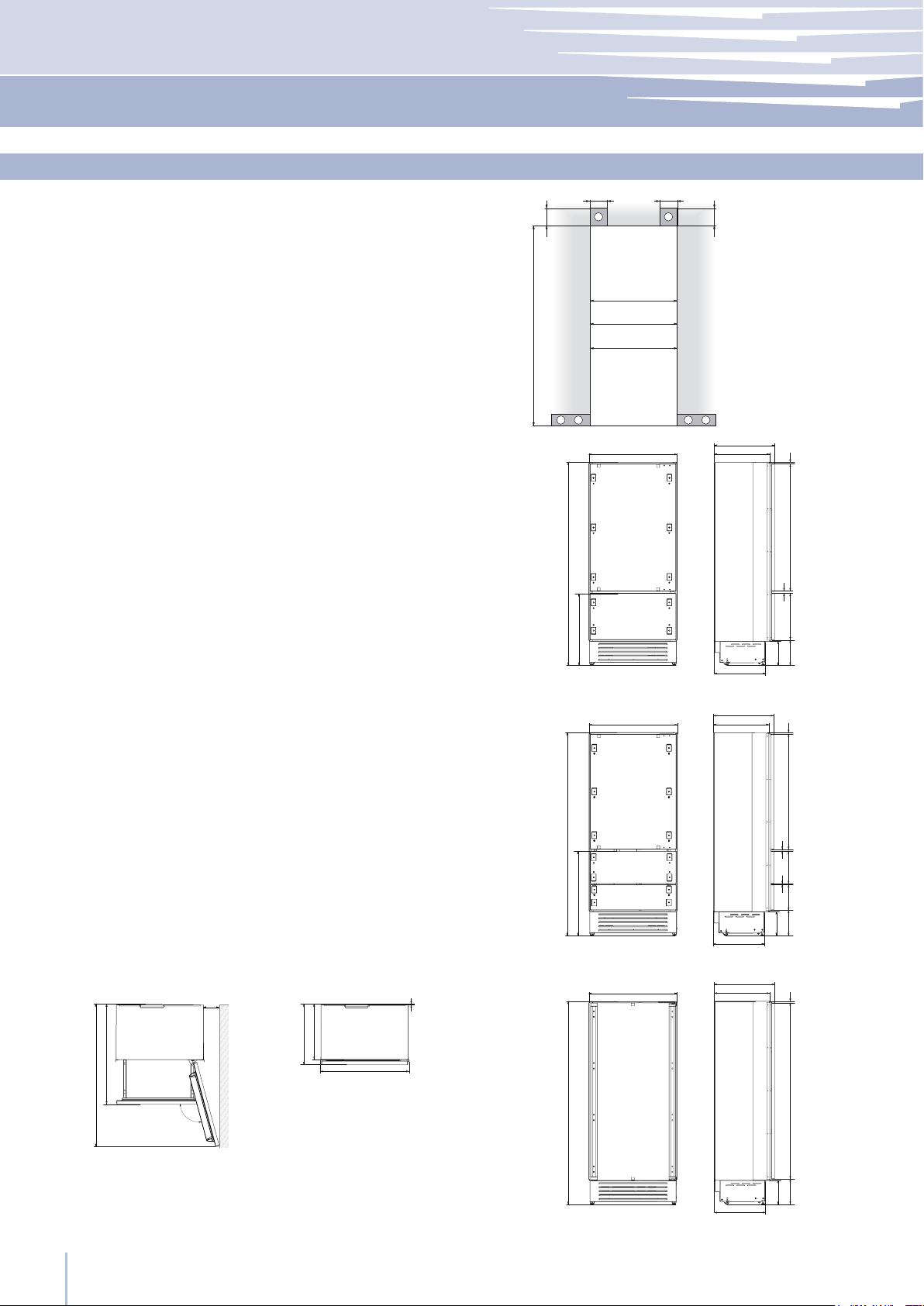
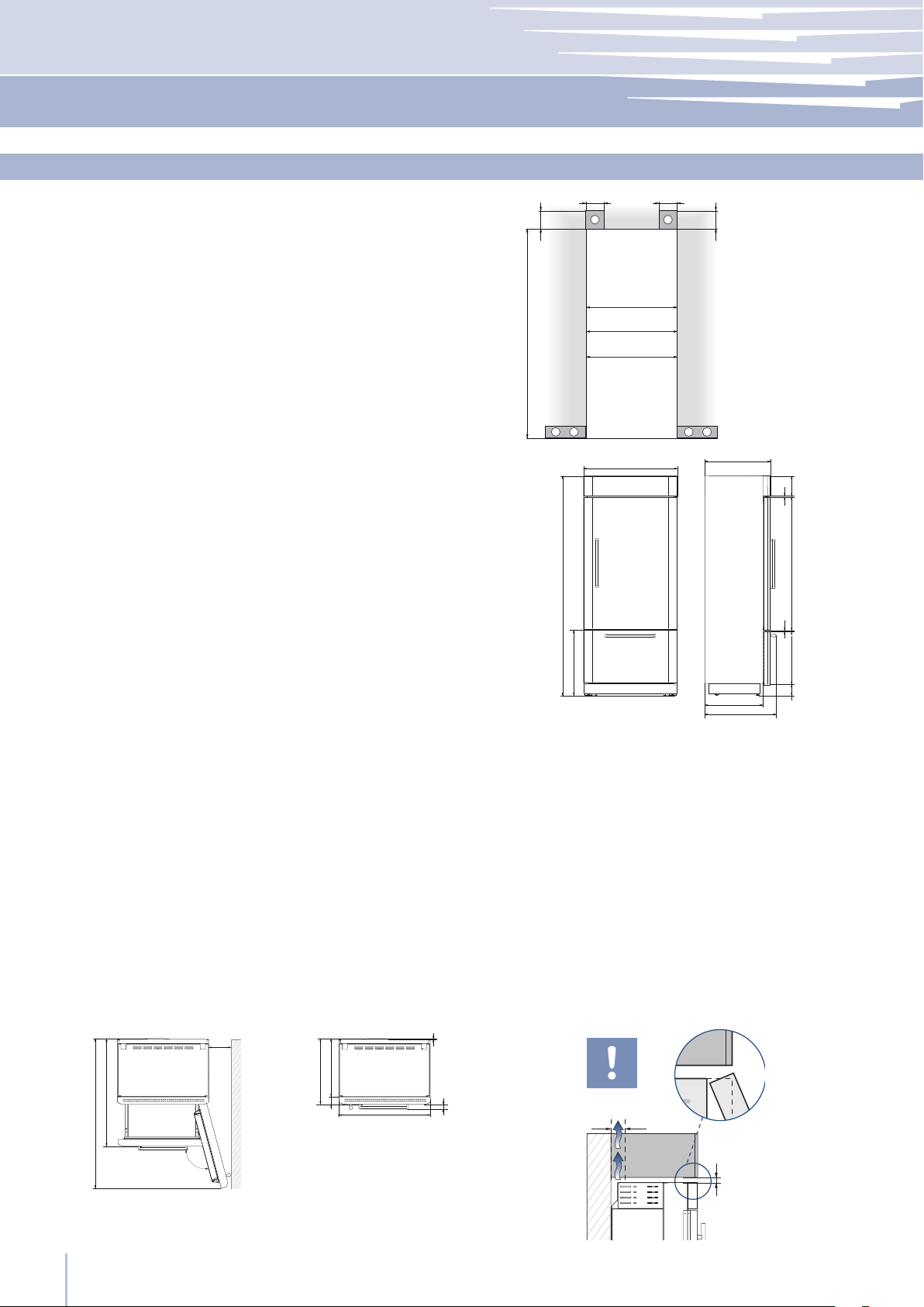
Installation niche features: Integrated Series
area to be left clear for the anti-tipping brackets
area to be left clear for the power supply cable
and water supply hose
Minimum Niche Height
Minimum Niche Width
Door Swing Clearance
Important: A 90° door opening is sufcient to allow
opening and full extraction of the inner drawers, even
if the appliance is installed directly adjacent to a wall.
Should an opening at 105° be desired, then the ap-
pliance should be positioned at the distance from the
wall described in gure.
area to be left clear for the anti-tipping brackets
area to be left clear for the power supply cable
and water supply hose
Minimum Niche Height
Minimum Niche Width
Door Swing Clearance
Door Opening Angle
Width
Height
Depth with door (without panel)
37
A
E
W
2064 mm (81 1/4”)
KS899: 900 mm (35 1/2”)
KS749: 750 mm (29 5/8”)
KS599: 600 mm (23 3/4”)
KS899: 1470 mm (57 7/8”)
KS749: 1320 mm (52”)
KS599: 1170 mm (46”)
105°
KS899: 899 mm (35 3/8”)
KS749: 749 mm (29 1/2”)
KS599: 599 mm (23 5/8”)
2050 mm (80 3/4”) + 25 mm (1”)
635 mm (25”)
min 2064 (81 ¼”)
A A
E W E W
140 (5 ½”) 140 (5 ½”)
100 (4”)
100 (4”)
KS899: 900 (35 ½”)
KS599: 600 (23 ¾”)
KS749: 750 (29 5⁄8”)
635 (25”)
560 (22”)
1T/0T
693 (27 ¼”)
2050 (80 ¾”) +25 (1”)
1308 (51 ½”)587 (23 1⁄8”)146 (5 ¾”) + 25(1”)
9 (
3⁄8”)
732 (28 7⁄8”)+25 (1”)
635 (25”)
560 (22”)
0F
693 (27 ¼”)
2050 (80 ¾”) +25 (1”)
1904 (75”)
146 (5
¾”) + 25(1”)
0H
635 (25”)
560 (22”)
693 (27 ¼”)
146 (5 ¾”) + 25(1”)
2050 (80 ¾”) +25 (1”)
857 (33 ¾”) +25 (1”)
1185 (46
5⁄8”)
342 (13 ½”)362 (14 ¼”)
9 ( 3⁄8”)6 ( ¼”)
KS899: 1470 (57 7⁄8”)
KS749: 1320 (52”)
KS599: 1170 (46”)
560 (22”)
635 (25”)
KS899: 899 (35 3⁄8”)
KS749: 749 (29 ½”)
KS599: 599 (23 5⁄8”)
10 (3⁄8”)
105°
75 (3”)
58 (2 ¼”)
KS899: 230 (9”)
KS749: 195 (7 ¾”)
KS599: 160 (6 ¼”)
1016 (40”)
www.fhiaba.com · [email protected] · Tel +39 (0)434 420160 · Fax +39 (0)434 420161
Installation Guide
EN
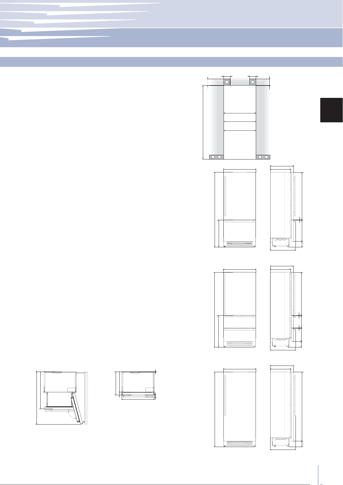
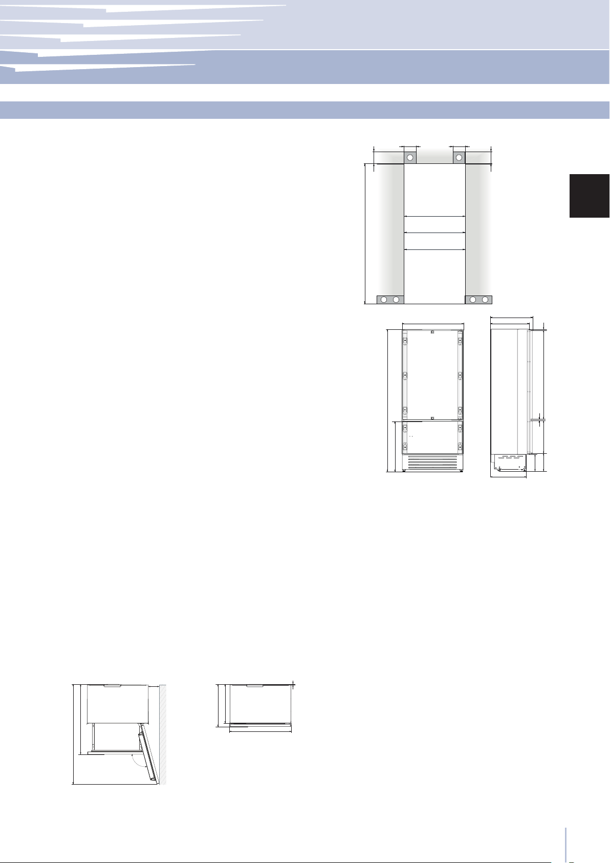
Installation niche features: Classic Series
Important: A 90° door opening is sufcient to allow
opening and full extraction of the inner drawers, even
if the appliance is installed directly adjacent to a wall.
Should an opening at 105° be desired, then the ap-
pliance should be positioned at the distance from the
wall described in gure.
area to be left clear for the anti-tipping brackets
area to be left clear for the power supply cable
and water supply hose
Minimum Niche Height
Minimum Niche Width
Door Swing Clearance
Door Opening Angle
Width
Height
Depth with door
38
A
E
W
2134 mm (84”)
MS899: 900 mm (35 1/2”)
MS749: 750 mm (29 5/8”)
MS599: 600 mm (23 3/4”)
MS899: 1470 mm (57 7/8”)
MS749: 1320 mm (52”)
MS599: 1170 mm (46”)
105°
MS899: 899 mm (35 3/8”)
MS749: 749 mm (29 1/2”)
MS599: 599 mm (23 5/8”)
2120 mm (83 1/2”) + 25 mm (1”)
629 mm (24 3/4”)
min 10
(⁄”)
min 50 (2”)
A A
E W E W
140 (5 ½”) 140 (5 ½”)
100 (4”)
100 (4”)
min 2134 (84”)
MS899: 900 (35 ½”)
MS599: 600 (23 ¾”)
MS749: 750 (29 5⁄8”)
560 (22”)
2120 (83 ½”) +25 (1”)
613 (24 1⁄8”)+25 (1”)
629 (24 ¾”)
615 (24 ¼”)
629 (24 ¾”)
615 (24 ¼”)
1T/0T
2120 (83 ½”) +25 (1”)
0H
666 (26 ¼”)
485 (19 1⁄8”)
1296 (50”)
195 (7 5⁄8”)
8 (3⁄8”)
8 (3⁄8”)
128 (5)
+ 25 (1”
)
128 (5)
+ 25 (1”)
195 (7 5⁄8”)
8 (3⁄8”)
8 (3⁄8”)
560 (22”)
666 (26 ¼”)
1170 (46”)
343 (13 ½”)
262 (10 ¼”)
6 (
¼”)
749 (29 ½”) + 25 (1”)
1010 (39 ¾”)
560 (22”)
MS899: 899 (35 ⁄”)
MS749: 749 (29
½”)
MS599: 599 (23 ⁄”)
10 (
⁄
”)
105°
629 (24 ¾”)
37 (1 ½”)
69 (2 ¾”)
MS899: 1470 (57 ⁄”)
MS749: 1320 (52”
)
MS599: 1170 (46”
)
MS899: 230 (9”)
MS749: 195 (7 ¾”)
MS599: 160 (6 ¼”)
www.fhiaba.com · [email protected] · Tel +39 (0)434 420160 · Fax +39 (0)434 420161
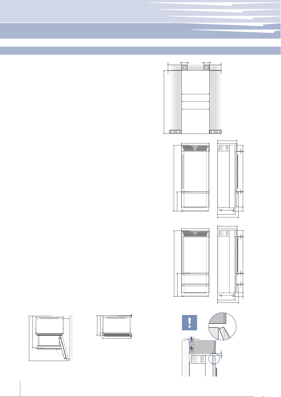
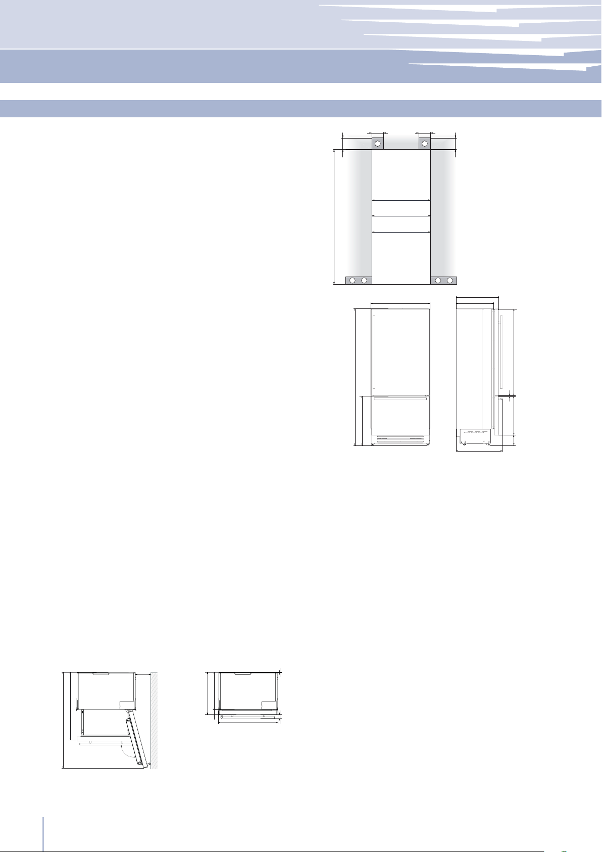
Installation niche features: StandPlus Series
Important: A 90° door opening is sufcient to allow
opening and full extraction of the inner drawers, even
if the appliance is installed directly adjacent to a wall.
Should an opening at 105° be desired, then the ap-
pliance should be positioned at the distance from the
wall described in gure.
area to be left clear for the anti-tipping brackets
area to be left clear for the power supply cable
and water supply hose
Minimum Niche Height
Minimum Niche Width
Door Swing Clearance
Door Opening Angle
Width
Height
Depth with door
Important: If the units are to be installed inside a ni-
che or within an enclosed structure, it is necessary to
design a ventilation shaft at the back of the niche to
assure proper ventilation at the back of the unit.
39
min 10 (⁄”)
min 50 (2”)
A
E
W
2134 mm (84”)
XS899: 900 mm (35 1/2”)
XS749: 750 mm (29 5/8”)
XS599: 600 mm (23 3/4”)
XS899: 1470 mm (57 7/8”)
XS749: 1320 mm (52”)
XS599: 1170 mm (46”)
105°
XS899: 899 mm (35 3/8”)
XS749: 749 mm (29 1/2”)
XS599: 599 mm (23 5/8”)
2120 mm (83 1/2”) + 25 mm (1”)
635 mm (25 ”)
A A
E W E W
140 (5 ½”) 140 (5 ½”)
100 (4”)
100 (4”)
min 2134 (84”)
XS899: 900 (35 ½”)
XS599: 600 (23 ¾”)
XS749: 750 (29 5⁄8”)
560 (22”)
2120 (83 ½”) +25 (1”)
613 (24 1⁄8”)+25 (1”)
2120 (83 ½”) +25 (1”)
635 (25”)
693 (27 ¼”)
516 (20 3⁄8”)
1296 (50”)
195 (7 5⁄8”)
8 (3⁄8”)
8 (3⁄8”)
195 (7 5⁄8”)
8 (3⁄8”)
8 (3⁄8”)
749 (29 ½”) + 25 (1”
)
1170 (46”)
343 (13 ½”)
293
(11 ½”)
6 (
¼”)
1T/0T
0H
97 (3 7⁄8”)
+ 25 (1”)
97 (3 7⁄8”)
+ 25 (1”)
1016 (40”)
XS899: 1470 (57 7⁄8”)
XS749: 1320 (52”)
XS599: 1170 (46”)
560 (22”)
75 (3”)
XS899: 899 (35 5⁄8”)
XS749: 749 (29
½”)
XS599: 599 (23 5⁄8”)
10 (3⁄8”)58 (2 ¼”)
105°
635 (25”)
XS899: 230 (9”)
XS749: 195 (7 ¾”)
XS599: 160 (6 ¼”)
www.fhiaba.com · [email protected] · Tel +39 (0)434 420160 · Fax +39 (0)434 420161
Installation Guide
EN
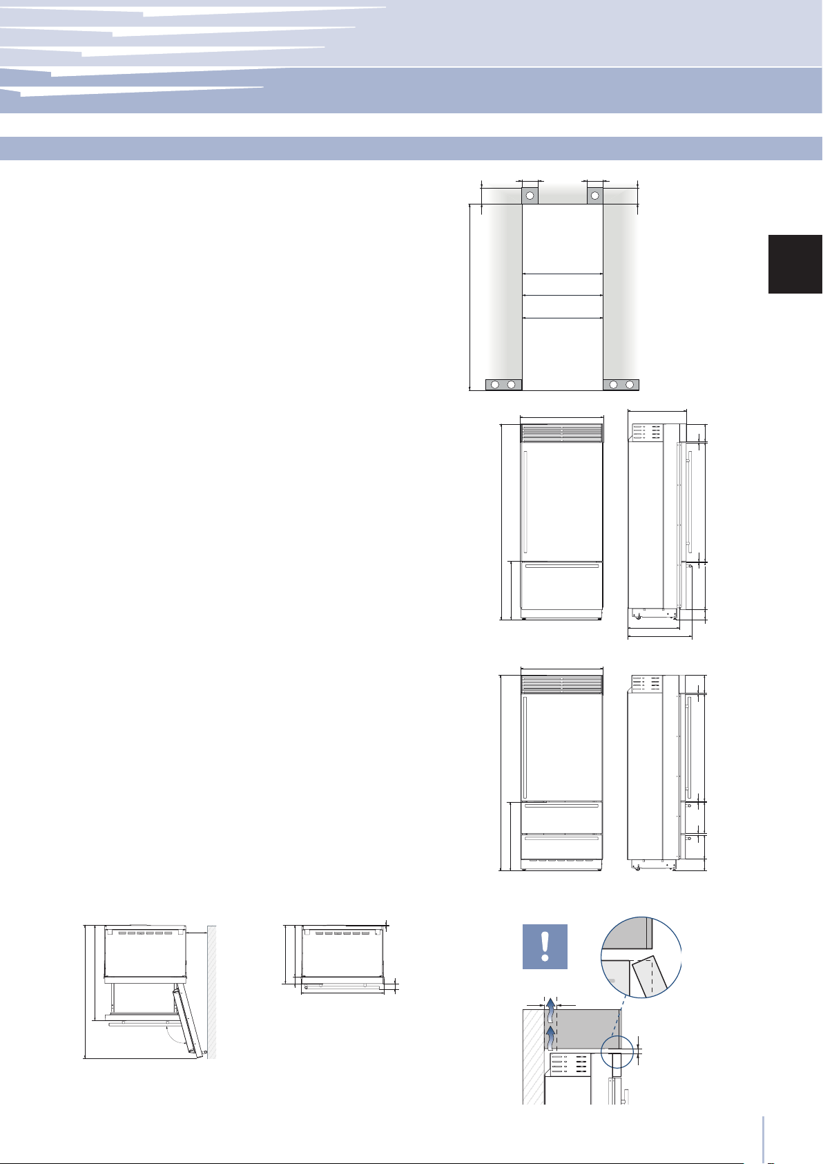
Installation niche features: X-Pro Series
Important: A 90° door opening is sufcient to allow
opening and full extraction of the inner drawers, even
if the appliance is installed directly adjacent to a wall.
Should an opening at 105° be desired, then the ap-
pliance should be positioned at the distance from the
wall described in gure.
area to be left clear for the anti-tipping brackets
area to be left clear for the power supply cable
and water supply hose
Minimum Niche Height
Minimum Niche Width
Door Swing Clearance
Door Opening Angle
Width
Height
Depth with door
Important: If the units are to be installed inside a ni-
che or within an enclosed structure, it is necessary to
design a ventilation shaft at the back of the niche to
assure proper ventilation at the back of the unit.
40
min 10 (⁄”)
min 50 (2”)
A
E
W
2134 mm (84”)
AS899: 900 mm (35 1/2”)
AS749: 750 mm (29 5/8”)
AS599: 600 mm (23 3/4”)
AS899: 1470 mm (57 7/8”)
AS749: 1320 mm (52”)
AS599: 1170 mm (46”)
105°
AS899: 887 mm (35")
AS749: 737 mm (29")
AS599: 587 mm (23 1/8")
2120 mm (83 1/2”) + 25 mm (1”)
635 mm (25 ”)
A A
E W E W
140 (5 ½”) 140 (5 ½”)
100 (4”)
100 (4”)
min 2134 (84”)
AS899: 900 (35 ½”)
AS599: 600 (23 ¾”)
AS749: 750 (29 5⁄8”)
560 (22”)
2120 (83 ½”) +25 (1”)
613 (24 1⁄8”)+25 (1”)
635 (25”)
695 (27 ¼”)
485 (19 1⁄8”)
1296 (50”)
195 (7 5⁄8”)
8 (3⁄8”)
8 (3⁄8”)
1T/0T
128 (5)
+ 25 (1”)
1016 (40”)
AS899: 1470 (57 7⁄8”)
AS749: 1320 (52”)
AS599: 1170 (46”)
560 (22”)
75 (3”)
AS899: 887 (35”)
AS749: 737 (29”)
AS599: 587 (23 1⁄8”)
10 (3⁄8”)60 (2 ¼”)
105°
635 (25”)
AS899: 230 (9”)
AS749: 195 (7 ¾”)
AS599: 160 (6 ¼”)
www.fhiaba.com · [email protected] · Tel +39 (0)434 420160 · Fax +39 (0)434 420161
Installation niche features: Country Series
Important: A 90° door opening is sufcient to allow
opening and full extraction of the inner drawers, even
if the appliance is installed directly adjacent to a wall.
Should an opening at 105° be desired, then the ap-
pliance should be positioned at the distance from the
wall described in gure.
area to be left clear for the anti-tipping brackets
area to be left clear for the power supply cable
and water supply hose
Minimum Niche Height
Minimum Niche Width
Door Swing Clearance
Door Opening Angle
Width
Height
Depth with door
41
A A
E W E W
140 (5 ½”) 140 (5 ½”)
100 (4”)
100 (4”)
min 2064 (81 ¼”)
BI899: 900 (35 ½”)
BI599: 600 (23 ¾”)
BI749: 750 (29 5⁄8”)
575 (22 5⁄8”)
525 (20
5⁄8”)
1293 (50 7⁄8” )
474 (18
5⁄8”)
231 (9
1⁄8”
) +
25 (1”)
465 (18 3⁄8”)
248 (9
¾”
)
+ 25 (1”)
20 (
¾”)
15 (
5⁄8”)
721 (28 3⁄8”) +25 (1”)
2050 (80
¾”) +25 (1”)
0T
947 (37 ¼”)
BI899: 1435 (56 ½”)
BI749: 1285 (50 5⁄8”)
BI599: 1135 (44
¾”)
525 (20 5⁄8”)
575 (22
5⁄8”)
BI899: 899 (35 3⁄8”)
BI749: 749 (29 ½”)
BI599: 599 (23 5⁄8”)
10 (
3⁄8
”)
105°
BI899: 160 (6 3⁄8”)
BI749: 125 (5”)
BI599: 90 (3 ½”)
A
E
W
2064 mm (81 1/4”)
BI899: 900 mm (35 1/2”)
BI749: 750 mm (29 5/8”)
BI599: 600 mm (23 3/4”)
BI899: 1435 mm (56 1/2” in)
BI749: 1285 mm (50 5/8” in)
BI599: 1135 mm (44 3/4” in)
105°
BI899: 899 mm (35 3/8”)
BI749: 749 mm (29 1/2”)
BI599: 599 mm (23 5/8”)
2050 mm (80 3/4”) + 25 mm (1”)
575 mm (22 5/8” in)
www.fhiaba.com · [email protected] · Tel +39 (0)434 420160 · Fax +39 (0)434 420161
Installation Guide
EN
Installation niche features: Brilliance-Integrated Series
Important: A 90° door opening is sufcient to allow
opening and full extraction of the inner drawers, even
if the appliance is installed directly adjacent to a wall.
Should an opening at 105° be desired, then the ap-
pliance should be positioned at the distance from the
wall described in gure.
area to be left clear for the anti-tipping brackets
area to be left clear for the power supply cable
and water supply hose
Minimum Niche Height
Minimum Niche Width
Door Swing Clearance
Door Opening Angle
Width
Height
Depth with door (without panel)
42
A
E
W
2064 mm (81 1/4”)
BKI899: 900 mm (35 1/2”)
BKI749: 750 mm (29 5/8”)
BKI599: 600 mm (23 3/4”)
BKI899: 1435 mm (56 1/2” in)
BKI749: 1285 mm (50 5/8” in)
BKI599: 1135 mm (44 3/4” in)
105°
BKI899: 899 mm (35 3/8”)
BKI749: 749 mm (29 1/2”)
BKI599: 599 mm (23 5/8”)
2050 mm (80 3/4”) + 25 mm (1”)
600 mm (23 3/4” in)
A A
E W E W
140 (5 ½”) 140 (5 ½”)
100 (4”)
100 (4”)
min 2064 (81
¼”)
BKI899: 900 (35 ½”)
BKI599: 600 (23 ¾”)
BKI749: 750 (29 5⁄8”)
600 (23 ¾”)
525 (20
5⁄8”)
0T
693 (27 ¼”)
2050 (80 ¾”) +25 (1”)
1308 (51 ½”)587 (23 1⁄8”)
146 (5
¾”) + 25(1”)
9 (
3⁄8”)
732 (28 7⁄8”)+25 (1”)
BKI899: 1435 (56 ½”)
BKI749: 1285 (50
5⁄8”)
BKI599: 1135 (44
¾”)
525 (20 5⁄8”)
600 (23
¾”)
BKI899: 899 (35 3⁄8”)
BKI749: 749 (29 ½”)
BKI599: 599 (23 5⁄8”)
10 (3⁄8”)
105°
75 (3”)
58 (2 ¼”)
BKI899: 230 (9”)
BKI749: 195 (7 ¾”)
BKI599: 160 (6 ¼”)
www.fhiaba.com · [email protected] · Tel +39 (0)434 420160 · Fax +39 (0)434 420161
Installation niche features: Brilliance-Classic Series
Important: A 90° door opening is sufcient to allow
opening and full extraction of the inner drawers, even
if the appliance is installed directly adjacent to a wall.
Should an opening at 105° be desired, then the ap-
pliance should be positioned at the distance from the
wall described in gure.
area to be left clear for the anti-tipping brackets
area to be left clear for the power supply cable
and water supply hose
Minimum Niche Height
Minimum Niche Width
Door Swing Clearance
Door Opening Angle
Width
Height
Depth with door
EW
E W
EW
E W
43
1
4
1
2
3
www.fhiaba.com · [email protected] · Tel +39 (0)434 420160 · Fax +39 (0)434 420161
Installation Guide
EN
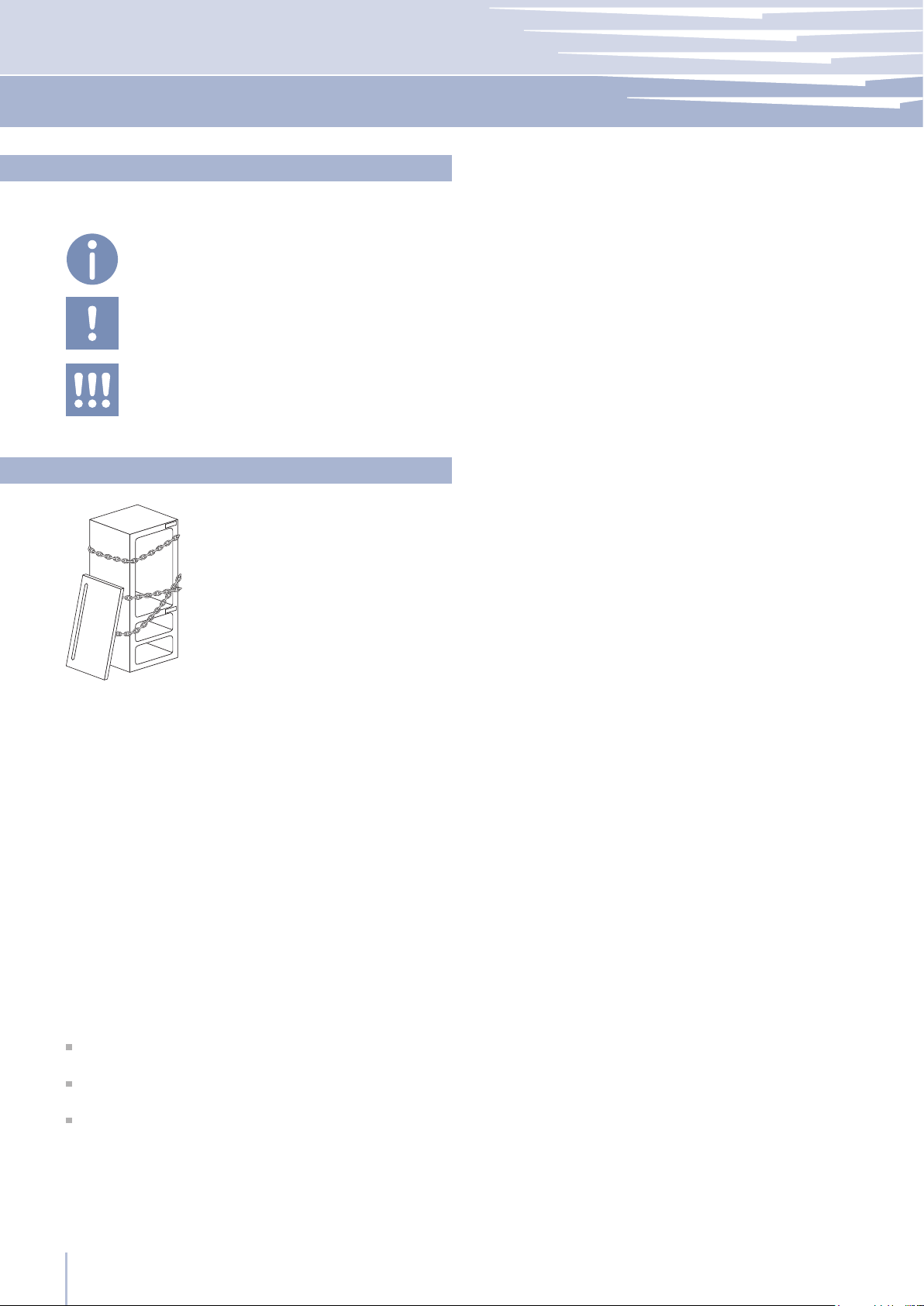
The appliance is very heavy.
Take maximum care during handling to avoid injury.
The appliance should always be transported in an erect
position.
Avoid at all costs leaning it on its front side.
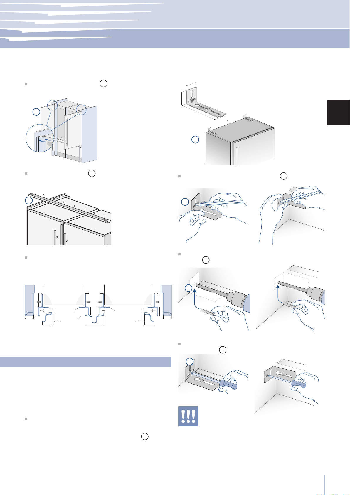
Preparing the installation
Transport to installation site and unpacking
Since this is a large and heavy appliance, before trans-
porting the appliance, check the access to the location
where it will be installed (door size, manoeuvring space in
stairwells, etc.).
The appliance is attached to the base of the packaging
(pallet) through four bolts which can be removed using a
17 mm (3/4”) wrench.
It is recommended to use a manual transporting device to
move the appliance to the installation site, and only at this
point to remove the base of the packaging.
The appliance should always be transported in an erect
position.
If this is not possible, transport the appliance laying on its
rear side.
Once at the installation site, the appliance, which is
equipped with four wheels, can be taken off the pallet and
positioned in the installation area.
Operate as follows:
Take off the four bolts
1
securing the appliance to the
pallet by means of a 17 mm (3/4”) open spanner.
Remove the xing brackets
3
and
4
.
To remove the front xing bracket
3
, unscrew
for one or two turns the rear wheel adjusting bolt
2
by means of a 13 mm (1/2”) box spanner, avoiding
too much strenght while thightening the nut, which
could damage the leveling feet adjusting system.
From the back of the unit and by means of a suitable,
high duty hand trolley, take off the appliance and place
it on the oor.
Be very careful to avoid any damage to oors. Delicate oors
should be protected with plywood, hard cardboard or similar
material panels.
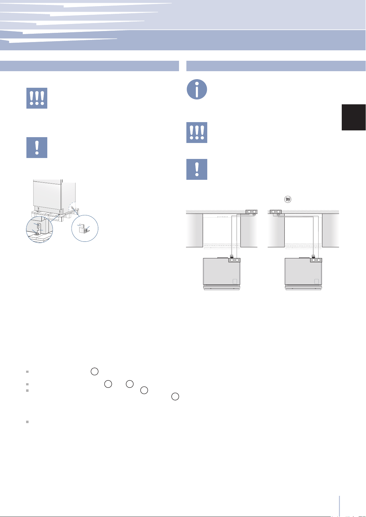
Electrical and Water connection
A Schuko 16 A socket with an efcient grounding should
be made available for the electrical mains connection, as
well as an omnipolar
switch which can easily be reached when the appliance
is installed.
To connect to the water supply system (for appliances
equipped with ice makers) a tap with a male 3/4” connec-
tion should be provided, which must also be easily acces-
sible once the appliance is installed.
The appliance is provided with a water supply hose and
seal kit which is suitable for high water pressure and com-
plies the Food Regulations.
The water lter cartridge, which is provided with the appli-
ance, should be installed according to the accompanying
instructions.
Use only the new hose and the new gaskets which are sup-
plied with the appliance. Discard any hose and gasket
which may have already been installed.
Electrical cord length: 2,0 mt (78 3/4”)
Water connection line length: 2,5 mt (98 3/8”)
Do not use extension cords or adapters.
Once the appliance has been connected to the water system,
turn the Ice Maker off (touch the button
on control panel to
switch it off) before the main water is shut off.
The appliance should be connected only to a drinkable
water supply system.
The Built-in Fhiaba lter cannot make it safe to drink any
water which is not suitable for human consumption.
2
1
2
1
44
E
W
E
W
1
2
1
2
www.fhiaba.com · [email protected] · Tel +39 (0)434 420160 · Fax +39 (0)434 420161
Energy: Alternatives and Home Automation
If energy is supplied through an alternative energy power
source (solar, geothermal, etc..) or if home automation
systems are installed, it is necessary to install the Alterna-
tive Energy Kit to integrate the unit into the power grid.
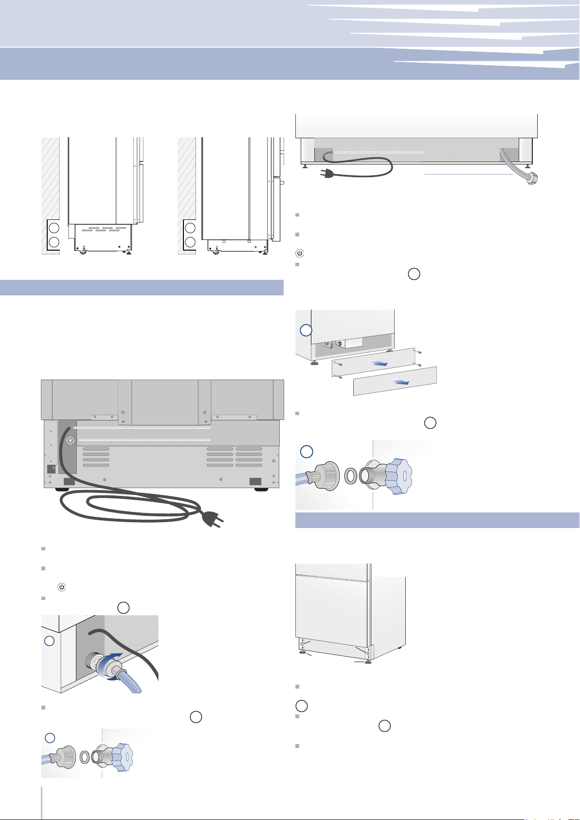
Electrical and water supply behind the unit
Integrated and Classic Series
Integrated and Classic Series
StandPlus, X-Pro and
Country Series
StandPlus, X-Pro and Country Series
Water connection
Electrical connection
Operate as follows:
Unwind the electric cable and connect it directly to the
wall socket.
Make sure the appliance is in the Stand-by condition and
that all lights are off; should it be not so press the Unit but-
ton to switch it off.
Fit one end of the water hose onto the connector at the
appliance’s back
1
.
Fit the other end of the hose to the water tap, use the
gaskets provided in the Owner’s Kit
2
.
Back of appliance
Operate as follows:
Unwind the electric cable and connect it directly to the
wall socket.
Make sure the appliance is in the Stand-by condition and
that all ights are off; should it be not so press the Unit button
to switch it off.
Connect the water line to the threaded connection at the
base of the unit, as in gure
1
.
Fit the other end of the hose to the water tap, use the gas-
kets provided in the Owner’s Kit
2
.
Back of appliance
Front of appliance
Water connection
Electrical connection
Adjust the appliance level by means of the front levelling
feet and the rear adjustable wheels.
Operate as follows:
After removing the bottom plinth or grille (it is kept in
position by magnets), adjust the height of the levelling feet
1
by means of a 17 mm (3/4”) open spanner.
Then adjust the height of the rear wheels by turning the
front adjusting bolts
2
clockwise or anticlockwise as it may
be required.
Remount the bottom plinth or grille.
Levelling
45
1
2
3
7
8
4
5
6
www.fhiaba.com · [email protected] · Tel +39 (0)434 420160 · Fax +39 (0)434 420161
Installation Guide
EN
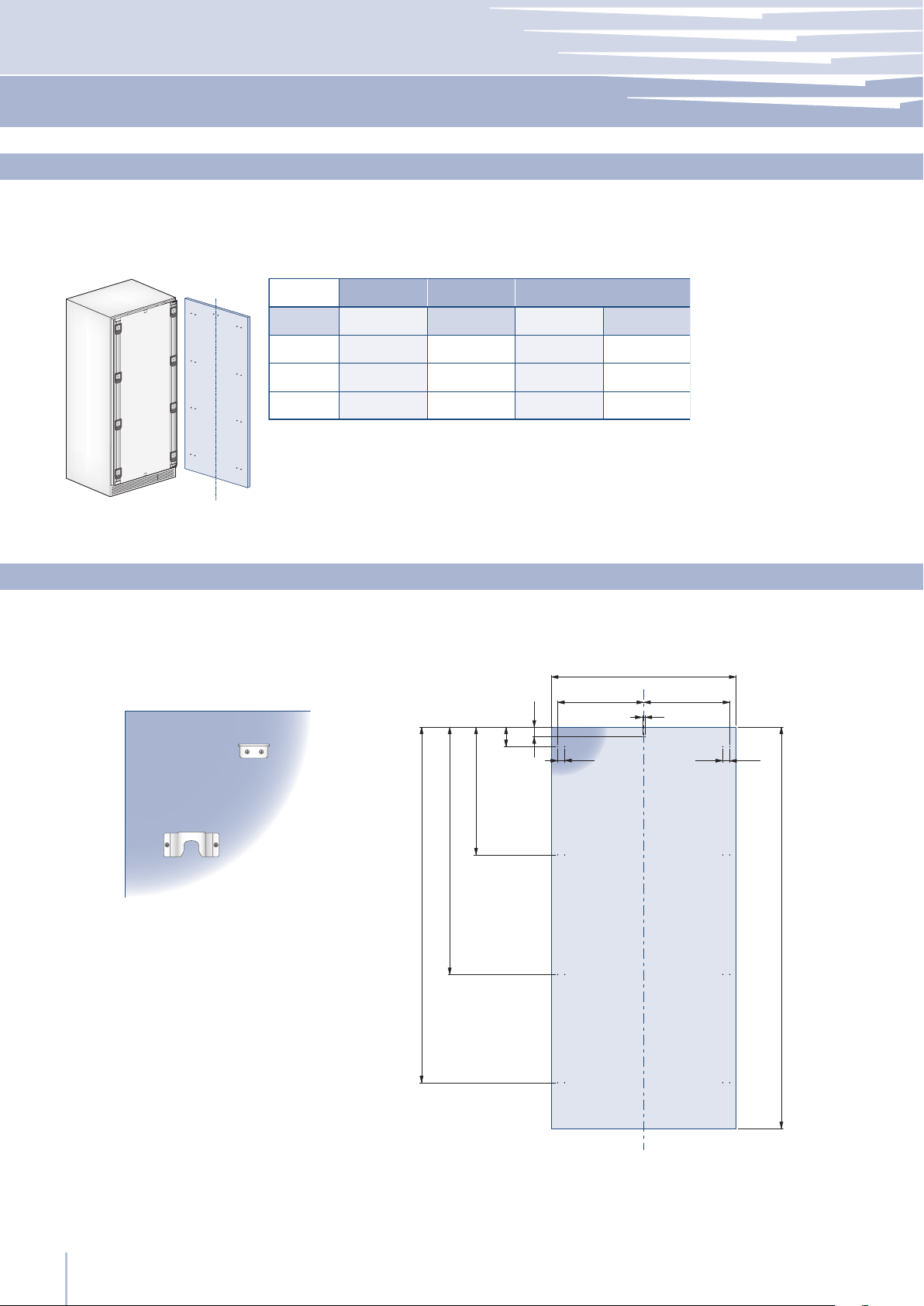
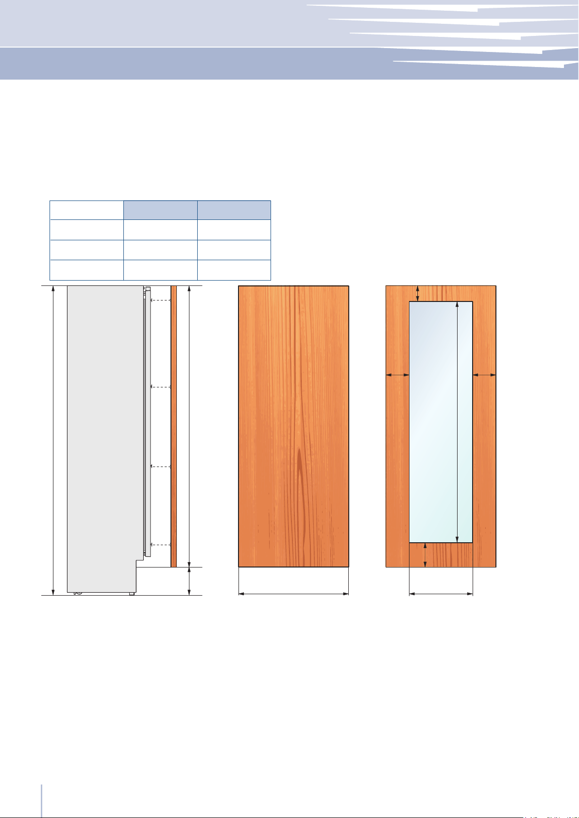
Decorative door and bottom-
drawer panels layout
The dimensions of the panels are indicated in the table
and drawings on next pages.
Nevertheless, according to the requirements for aligning
with other kitchen structures, the door panel can be high-
er than the upper edge of the refrigerator door, and the
drawer panel can be lower than the edge of the drawer.
The panels must be mounted using special braces which
attach to adjustable devices provided on the door and
drawer and with brackets that anchor and adjust the
panel’s vertical direction.
Braces, brackets and fixing screws are provided with the
appliance and must be applied to the panel as indicat-
ed.
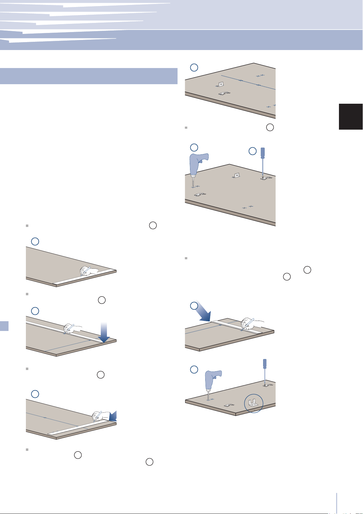
Operate as follows:
To prepare the panels to be mounted on the appliance,
follow these steps, working on the back of the panel.
Door Panel
Trace, a line dividing the panel width in half
1
.
Starting form the Bottom edge of the panel, mark the
positioning of the brackets
2
.
Following the corresponding table, mark the external
and then the internal hole
3
.
Position the brackets on each set of marks to make sure
they are aligned
4
, then drill holes through the panel
(pay close attention to the panel’s thickness)
5
.
Screw the brackets in place
6
.
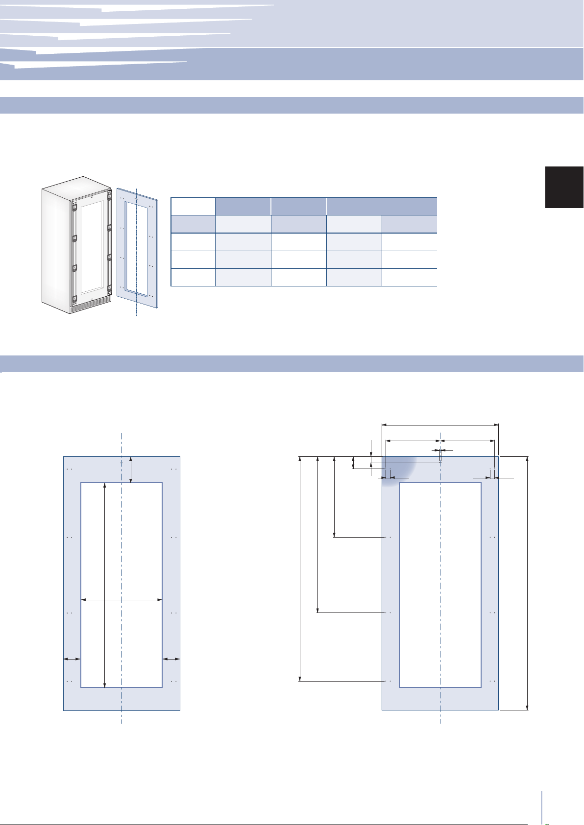
Drawer Panel
When preparing the Drawer Panel, follow the same in-
structions as per the door panel, but make sure measure-
ments are taken starting from the top edge
7
. The sup-
port bracket faces the opposite way
8
(note imgs 4 and
8).
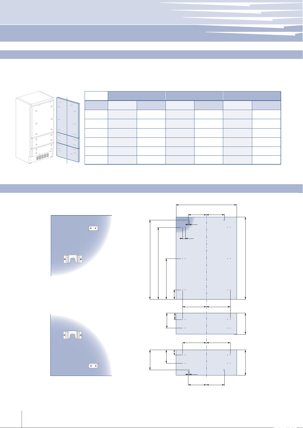
Integrated Series
46
D E
D E
A
B C
F G
13 (½”)
13 (
½”)
34 (1
⁄”)
34 (1
⁄”)
1285 (50 ⁄”)
1163 (45 ¾”)
660 (26”)
157 (6
¼”)
min 1320 (52”)
max 635 (25”
)
507,5 (20”)
382 (15
1⁄8”)
100 (4”)
A
897 (35
¼”) 897 (35
¼”) 747 (29 ⁄”) 747 (29 ⁄”) 597 (23 ½”)
355,5 (14”)
355,5 (14”)
279 (11”)
279 (11”)
205 (8 1⁄8”)
205 (8
1⁄8”)261 (10 ¼”)
261 (10 ¼”)
187 (7 ⁄”)
187 (7
⁄”)
111 (4
⁄”)
111 (4
⁄”)
418 (16
½”)
418 (16
½”)
343 (13
½”)
343 (13
½”)
276,5 (10
⁄”)
276,5 (10
⁄”)386 (15 ¼”)
386 (15
¼”)
311 (12
¼”)
311 (12
¼”)
236,5 (9
⁄”)
236,5 (9
⁄”)
B
C
D
E
354,5 (14”) 354,5 (14”) 279,5 (11”) 279,5 (11”) 203,5(8”)
597 (23
½”)
203,5(8”)F / G
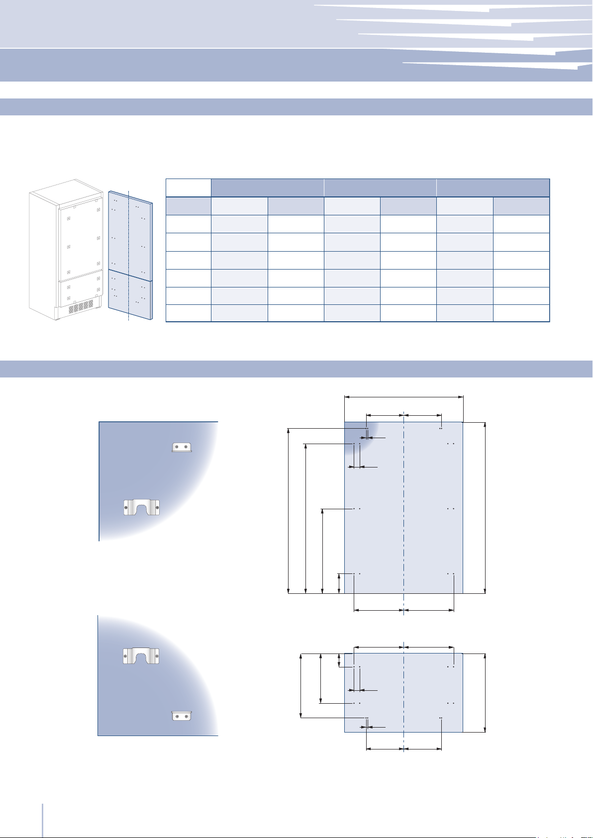
www.fhiaba.com · [email protected] · Tel +39 (0)434 420160 · Fax +39 (0)434 420161
Decorative panels layout for Fridge with one Bottom-Drawer (1T/0T)
Series 899
Hinge Left Hinge Left Hinge Left
Hinge Right Hinge Right Hinge Right
Series 749
Series 599
Holes positions
47
A
897 (35
¼”) 897 (35
¼”) 747 (29 ⁄”) 747 (29 ⁄”) 597 (23 ½”)
417 (16
⁄”)
417 (16
⁄”)
342 (13
½”)
342 (13
½”)
276,5 (10
7⁄8”)
276,5 (10
7⁄8”)417 (16 ⁄”)
417 (16 ⁄”)
342 (13 ½”)
342 (13
½”)
268 (11
¼”)
268 (11
¼”)
354,5 (14”) 279,5(11”) 203,5 (8”)354,5 (14”) 279,5(11”) 203,5 (8”)
B
C
D
597 (23 ½”)
A
BB
A
BB
C C
13 (½”)
34 (1
⁄”)
6,5 (
¼”)6,5 (¼”)
34 (1
⁄”)
1273 (50 1⁄8”)
1163 (45 ¾”)
660 (26”)
157 (6
¼”)
min 1390 (54
¾”)
max 635 (25”
)
507.5 (20”)
382 (15
1⁄8”)
100 (4”)
www.fhiaba.com · [email protected] · Tel +39 (0)434 420160 · Fax +39 (0)434 420161
Installation Guide
EN
Decorative panels layout for Fridge Brilliance
Series 899
Hinge Left Hinge Left Hinge Left
Hinge Right Hinge Right Hinge Right
Series 749
Series 599
Holes positions
48
D E
A
B
C
F G
D E
13 (½”)
13 (½”)
34 (1
⁄”)
min 1195 (47”)
1160 (45 ⁄”)
1044 (41 1⁄8”)
600 (23
⁄”)
268 (10
½”)
292,5 (11 ½”)
183 (7 ¼”)
73 (2
⁄”)
66 (2
⁄”) 157 (6 ¼”)
337 (13
¼”
)
max 415 (16
⁄”)
A
897 (35
¼”) 897 (35
¼”) 747 (29 ⁄”) 747 (29 ⁄”) 597 (23 ½”)
355,5 (14”)
355,5 (14”)
279 (11”)
279 (11”)
205 (8 1⁄8”)
205 (8
1⁄8”)261 (10 ¼”)
261 (10 ¼”)
187 (7 ⁄”)
187 (7
⁄”)
111 (4
⁄”)
111 (4
⁄”)
418 (16
½”)
418 (16
½”)
343 (13
½”)
343 (13
½”)
276,5 (10
⁄”)
276,5 (10
⁄”)386 (15 ¼”)
386 (15
¼”)
311 (12
¼”)
311 (12
¼”)
236,5 (9
⁄”)
236,5 (9
⁄”)
B
C
D
E
354,5 (14”) 354,5 (14”) 279,5 (11”) 279,5 (11”) 203,5(8”)
597 (23
½”)
203,5(8”)F / G
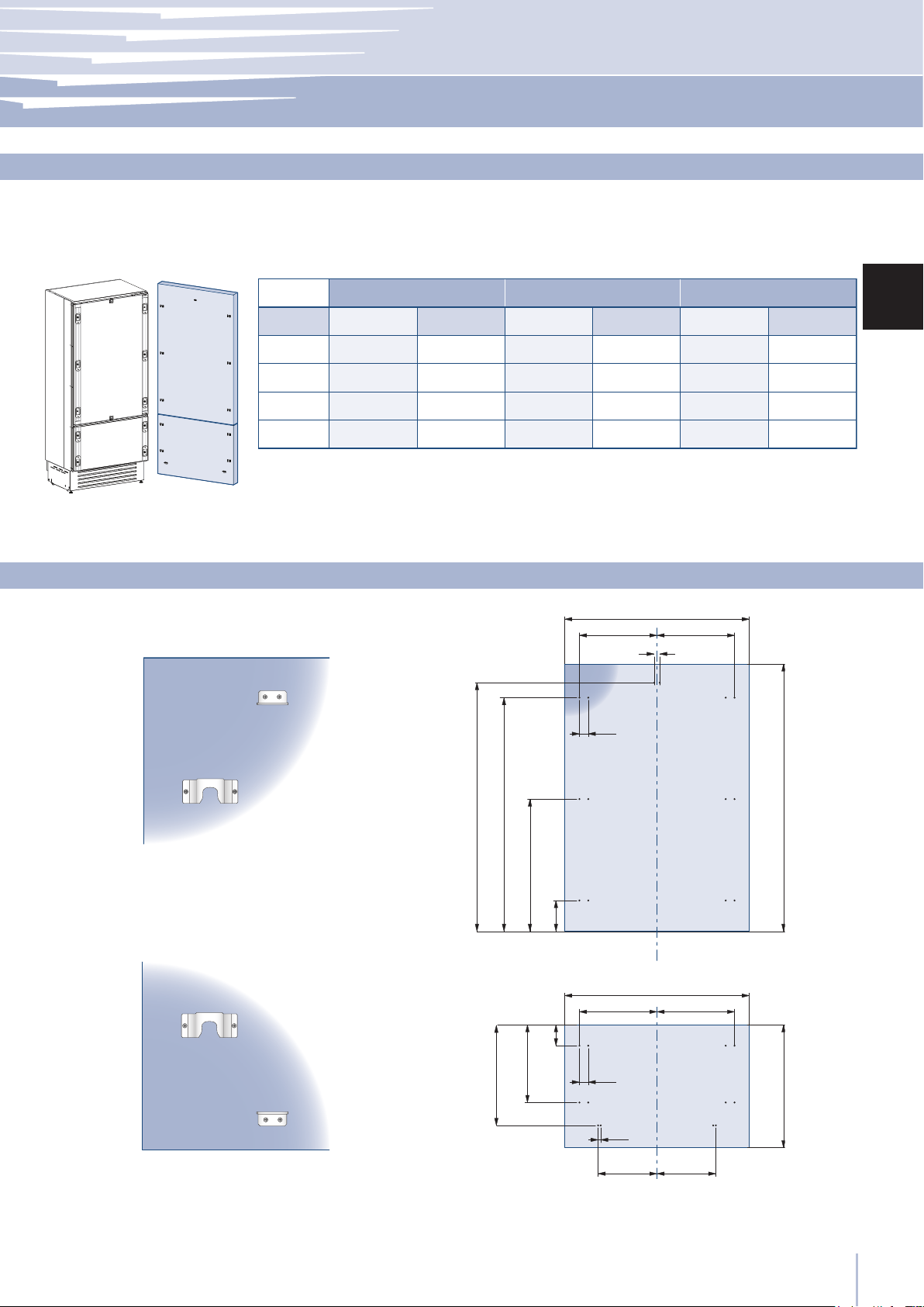
www.fhiaba.com · [email protected] · Tel +39 (0)434 420160 · Fax +39 (0)434 420161
Decorative panels layout for Fridge with two Bottom-Drawers (0H)
Holes positions
Series 899
Hinge Left Hinge Left Hinge Left
Hinge Right Hinge Right Hinge Right
Series 749
Series 599
49
H I
D E
A
F G
1286 (50 5⁄8”)
6,5 (¼”)
6,5 (
¼”)
1152,5 (45 3⁄8”)
650,5 (13
5⁄8”)
148,5 (5
⁄”)
13 (½”)
34 (1
3⁄8”)
34 (1 3⁄8”)
min 1320 (52”)
max 635 (25”
)
507,5 (20”)
382 (15
1⁄8”)
100 (4”)
899: 627 (24 5⁄8”)
749: 477 (18
¾”)
599: 327 (12
7⁄8”)
1075 (42 3⁄8”)
min 130 (5 1⁄8”
)
115 (4 ½”)
135 (5
3⁄8”)
135 (5
3⁄8”
)
A
H
I
F / G
897 (35 ¼”) 897 (35 ¼”)
747 (29
⁄”) 747 (29 ⁄”) 597 (23 ½”) 597 (23 ½”)
354,5 (14”) 354,5 (14”) 279,5 (11”) 279,5 (11”) 203,5(8”) 203,5(8”)
412 (16
¼”)
412 (16
¼”)
337 (13
¼”)
337 (13
¼”)
270,5 (10
⁄”)
270,5 (10
⁄”)380 (15”)
380 (15”)
305 (12”)
305 (12”)
230,5 (9
1⁄8”)
230,5 (9
1⁄8”)
418 (16
½”)
418 (16
½”)
343 (13
½”)
343 (13
½”)
276,5 (10
7⁄8”)
276,5 (10
7⁄8”)386 (15 ¼”)
386 (15
¼”)
311 (12
¼”)
311 (12
¼”)
236,5 (9
⁄”)
236,5 (9
⁄”)
D
E
www.fhiaba.com · [email protected] · Tel +39 (0)434 420160 · Fax +39 (0)434 420161
Installation Guide
EN
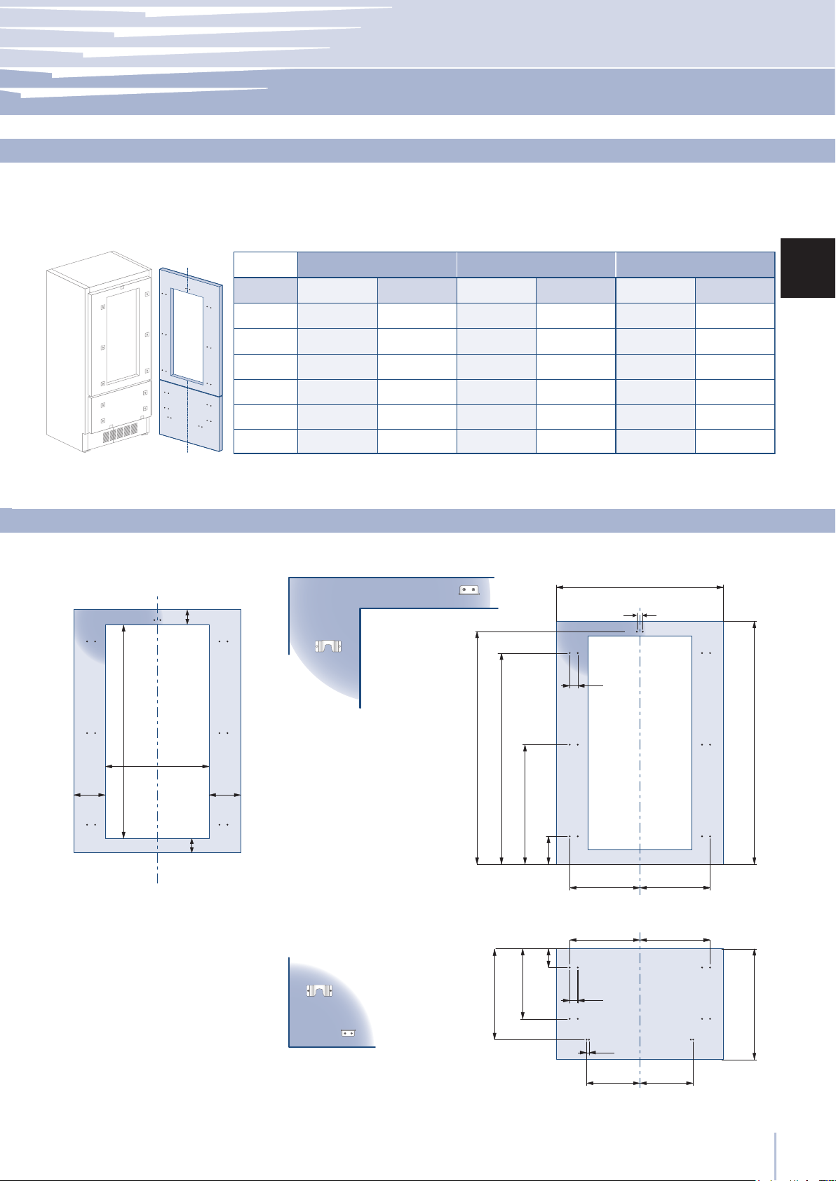
Decorative panels layout for Fridge with glass door and one Bottom-Drawer (1T/0T)
Holes positionsDoor window dimensions
Series 899
Hinge Left Hinge Left Hinge Left
Hinge Right Hinge Right Hinge Right
Series 749
Series 599
50
B C
B B
A
D D
1273 (50 1⁄8”)
6,5 (¼”)
6,5 (
¼”)
1152,5 (45 3⁄8”)
650,5 (13
5⁄8”)
148,5 (5
7⁄8”)
13 (½”)
34 (1
3⁄8”)
34 (1 3⁄8”)
min 1320 (52”)
max 635 (25”)
507,5 (20”)
382 (15
1⁄8”)
100 (4”)
599: 327 (12 7⁄8”)
1075 (42 3⁄8”)
min 130 (5 1⁄8”
)
115 (4 ½”)
135 (5
3⁄8”)
135 (5
3⁄8”
)
A
D
597 (23 ½”) 597 (23 ½”)
203,5(8”) 203,5(8”)
276,5 (10
7⁄8”)
276,5 (10
7⁄8”)268 (10
½”)
268 (10
½”)
B
C
www.fhiaba.com · [email protected] · Tel +39 (0)434 420160 · Fax +39 (0)434 420161
Decorative panels layout for Fridge with glass door Brilliance
Holes positionsDoor window dimensions
Series 599
Hinge Left
Hinge Right
51
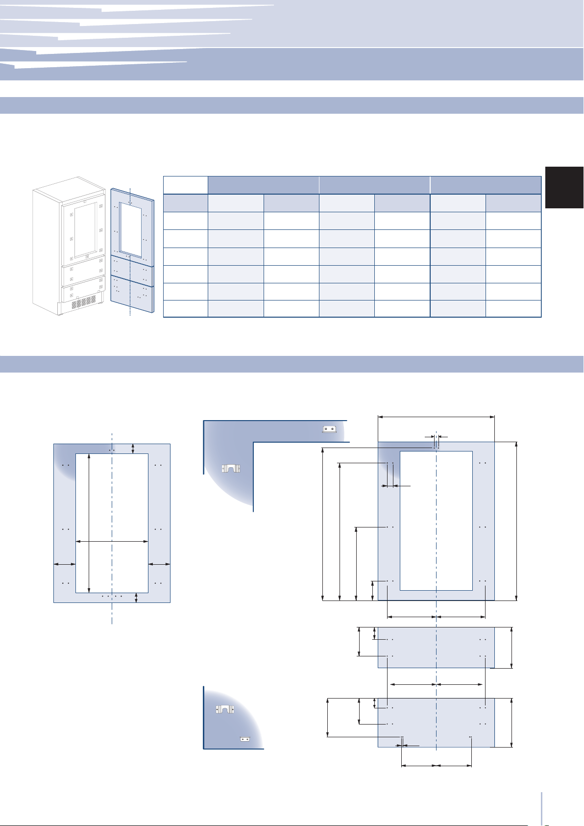
950 (37 ⁄”)
899: 627 (24 ¾”)
749: 477 (18
¾”)
599: 327 (12
7⁄8”)
115 (4
½”)
135 (5
⁄”)
135 (5
⁄”)
min 130 (5 1⁄8”)
A
H
I
F / G
897 (35 ¼”) 897 (35 ¼”)
747 (29
⁄”) 747 (29 ⁄”) 597 (23 ½”) 597 (23 ½”)
354,5 (14”) 354,5 (14”) 279,5 (11”) 279,5 (11”) 203,5(8”) 203,5(8”)
412 (16
¼”)
412 (16
¼”)
337 (13
¼”)
337 (13
¼”)
270,5 (10
⁄”)
270,5 (10
⁄”)380 (15”)
380 (15”)
305 (12”)
305 (12”)
230,5 (9
1⁄8”)
230,5 (9
1⁄8”)
418 (16
½”)
418 (16
½”)
343 (13
½”)
343 (13
½”)
276,5 (10
7⁄8”)
276,5 (10
7⁄8”)386 (15 ¼”)
386 (15
¼”)
311 (12
¼”)
311 (12
¼”)
236,5 (9
⁄”)
236,5 (9
⁄”)
D
E
F G
D E
6,5 (¼”)
6,5 (
¼”)
H I
A
1161 (45 ¾”)
1026,7 (40 ⁄”)
588 (23
1⁄8”)
149,5 (5
⁄”)
13 (½”)
34 (1
⁄”)
min 1195 (47”)
268 (10
½”)
292,5 (11 ½”)
183 (7
¼”)
73 (2 ⁄”)
66 (2
5⁄8”)
337 (13
¼”)
m 415 (16
3⁄8”)
www.fhiaba.com · [email protected] · Tel +39 (0)434 420160 · Fax +39 (0)434 420161
Installation Guide
EN
Decorative panels layout for Fridge with glass door and two Bottom-Drawers (0H)
Holes positionsDoor window dimensions
Hinge Left Hinge Left
Hinge Right Hinge Right
52
1
A
897 (35 ¼”)
418 (16
½”)
418 (16 ½”)
747 (29
⁄”)
343 (13
½”)
343 (13
½”)
597 (23 ½”) 597 (23 ½”)
276,5 (10
7⁄8”)
276,5 (10
7⁄8”)268 (10
½”)
268 (10
½”)
B
C
13 (½”)
min 1863 (73 3⁄8”)
95 (3 ¾”)
1201,5 (47
3⁄8”)
620,5 (24
½”)
1727 (68”)
47 (1 7⁄8”)
B C
A
34 (1 3⁄8”) 34 (1 3⁄8”)
www.fhiaba.com · [email protected] · Tel +39 (0)434 420160 · Fax +39 (0)434 420161
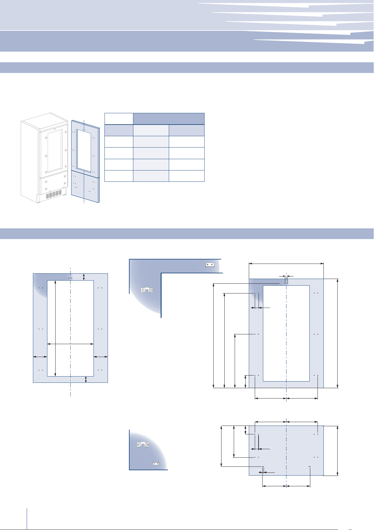
Decorative panels layout for Fridge Column (0F)
Holes positions
Series 899
Hinge Left
Hinge Right
Series 749 Series 599
53
1
A
897 (35 ¼”)
418 (16
½”)
418 (16 ½”)
747 (29
⁄”)
343 (13
½”)
343 (13
½”)
597 (23 ½”) 597 (23 ½”)
276,5 (10
7⁄8”)
276,5 (10
7⁄8”)268 (10
½”)
268 (10 ½”)
B
C
13 (½”)
min 1863 (73 3⁄8”)
95 (3 ¾”)
1201,5 (47
3⁄8”)
620,5 (24
½”)
1727 (68”)
47 (1 7⁄8”)
B C
A
34 (1 3⁄8”) 34 (1 3⁄8”)
1572 (62”)
899: 627 (24 ¾”)
749: 477 (18
¾”)
599: 327 (12
7⁄8”)
135 (5
3⁄8”
)
135 (5 3⁄8”)
min 130
(5
1⁄8”)
www.fhiaba.com · [email protected] · Tel +39 (0)434 420160 · Fax +39 (0)434 420161
Installation Guide
EN
Series 899
Hinge Left
Hinge Right
Series 749 Series 599
Decorative panels layout for Fridge column with glass door (0F)
Holes positionsDoor window dimensions
54
899
749
599
897 (35 1/4”)
627 (24 3/4”)
747 (29 3/8”) 477 (18 3/4”)
597 (23 3/4”) 327 (12 7/8”)
B
115 (4 ½”)
min 130 (5 1⁄8”)
135
(5 3⁄8”)
135
(5 3⁄8”)
1075 (42 3⁄8”)
2050 (80 ¾”)
min 540 (21 ¼”)
m 35 (25)
187 (7
3⁄8”)
A
3 (1⁄8”)
1320 (52)
www.fhiaba.com · [email protected] · Tel +39 (0)434 420160 · Fax +39 (0)434 420161
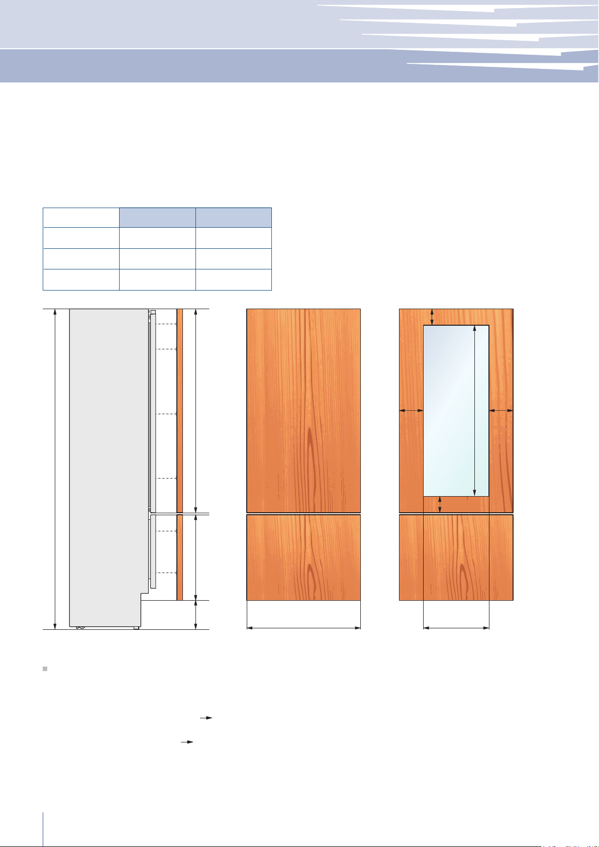
Examples of calculation
Integration in a kitchen column of total height 2160 mm (85”) and 150 mm (6”) kickplate.
(NOTE: In calculating the adjustment foot is considered to 0).
Drawer Calculation:
Kickplate 187 - 150 = 37 mm (1 1/2”) 540 + 37 = 577 mm (22 3/4”)
Upper Panel Calculation:
2160 - 2050 = 110 mm (4 3/8”) 1320 + 110 = 1430 mm (56 1/4”)
Total Height Calculation:
150 + 577 + 3 + 1430 = 2160 mm (85”)
Panels Dimensions One Bottom - Drawer (1T/0T models)
Door/Drawer Width
A
Series
Door Cutout Width
B
Panels with width ranging between 18 mm (3/4 in) and 28 mm (1 1/8 in).
Door panels with weight max of 23 kg (51 lb) and drawer panels with weight max of 11kg (25 lb).
Provide installation of decorative panels during installation of the unit.
55
897 (35 1/4”)
627 (24 3/4”)
747 (29 3/8”) 477 (18 3/4”)
597 (23 3/4”) 327 (12 7/8”)
899
749
599
min 325 (12 ¾”)
max 415 (16⁄”)
337 (13 ¼”)
3 (1⁄8”)
3 (1⁄8”)
1195 (47”)
2050 (80 ¾”)
187 (7
⁄”)
A B
115 (4 ½”)
135
(5 ⁄”)
135
(5 ⁄”)
min 130 (5 1⁄8”)
950 (37 ⁄”)
www.fhiaba.com · [email protected] · Tel +39 (0)434 420160 · Fax +39 (0)434 420161
Installation Guide
EN
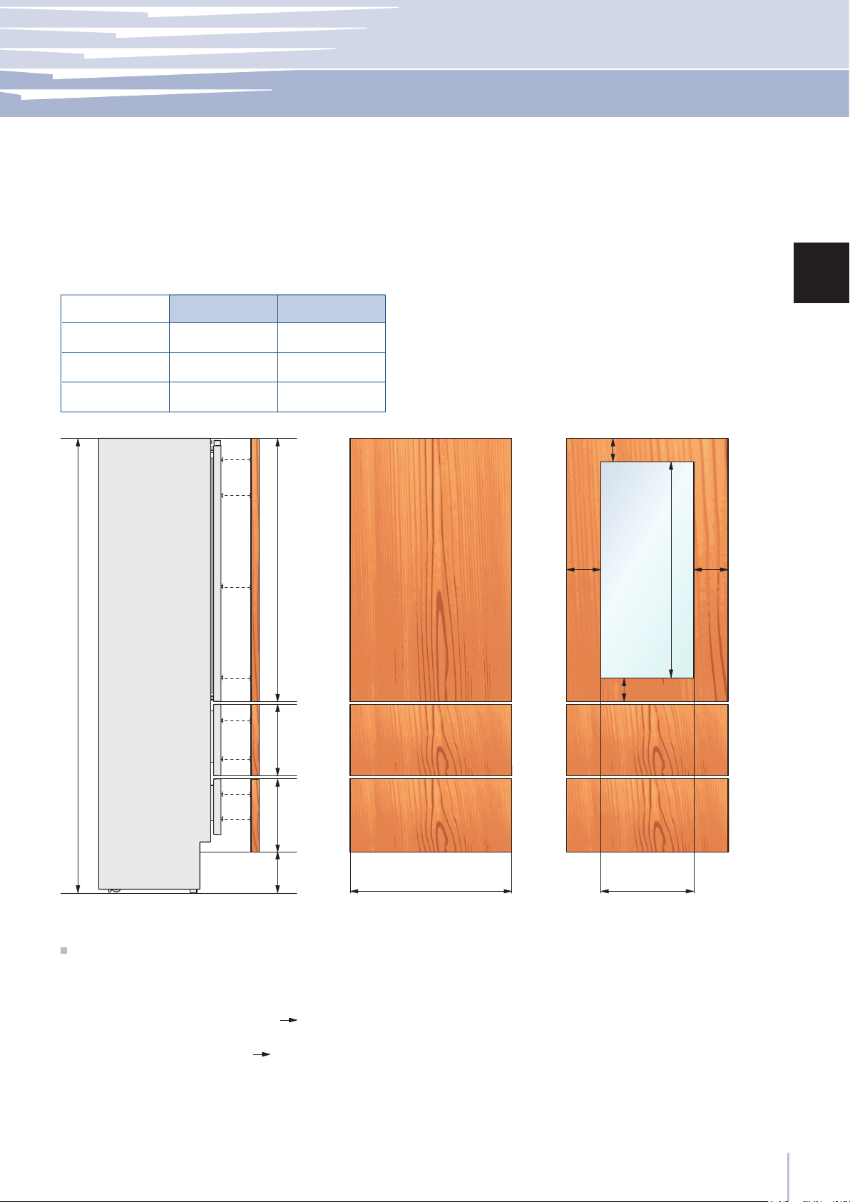
Examples of calculation
Integration in a kitchen column of total height 2160 mm (85”) and 150 mm (6”) kickplate.
(NOTE: In calculating the adjustment foot is considered to 0).
Inner Drawer Calculation:
Kickplate 187 - 150 = 37 mm (1 1/2”) 325 + 37 = 362 mm (14 1/4”)
Upper Panel Calculation:
2160 - 2050 = 110 mm (4 3/8”) 1195 + 110 = 1305 mm (51 3/8”)
Total Height Calculation:
150 + 362 + 3 + 337 + 3 + 1305 = 2160 mm (85”)
Panels DimensionsTwo Bottom - Drawers (0H models)
Door/Drawer Width
A
Series
Door Cutout Width
B
Panels with width ranging between 18 mm (3/4 in) and 28 mm (1 1/8 in).
Door panels with weight max of 23 kg (51 lb) and drawer panels with weight max of 11kg (25 lb).
Provide installation of decorative panels during installation of the unit.
56
min 1863 (73 ⁄”)
max 1960 (77 1⁄8”)
2050 (80 ¾”)
187 (7
⁄”)
A B
min 144 (5 ¾”)
max 239 (9 ⁄”)
135
(5 ⁄”)
135
(5 ⁄”)
min 130 (5 1⁄8”)
1572 (62”)
899
749
599
897 (35 1/4”)
627 (24 3/4”)
747 (29 3/8”) 477 (18 3/4”)
597 (23 1/2”) 327 (12 7/8”)
www.fhiaba.com · [email protected] · Tel +39 (0)434 420160 · Fax +39 (0)434 420161
Door/Drawer Width
A
Series
Door Cutout Width
B
Panels with width ranging between 18 mm (3/4 in) and 28 mm (1 1/8 in).
Door panels with weight max of 34 kg (75 lb).
Provide installation of decorative panels during installation of the unit.
Panels Dimensions Column Models (0F models)
57
1
2
480 mm (18
7/8”)
899
900 mm (35
1/2”)
899
749
599
490 mm (19
1/4”)
749
340 mm (13
3/8”)
599
794 mm (31
1/4”)
1104 mm (43
1/2”)
644 mm (25
3/8”)
494 mm (19
5/8”)
HO8HV HO7
HO5
1
2
3
www.fhiaba.com · [email protected] · Tel +39 (0)434 420160 · Fax +39 (0)434 420161
Installation Guide
EN
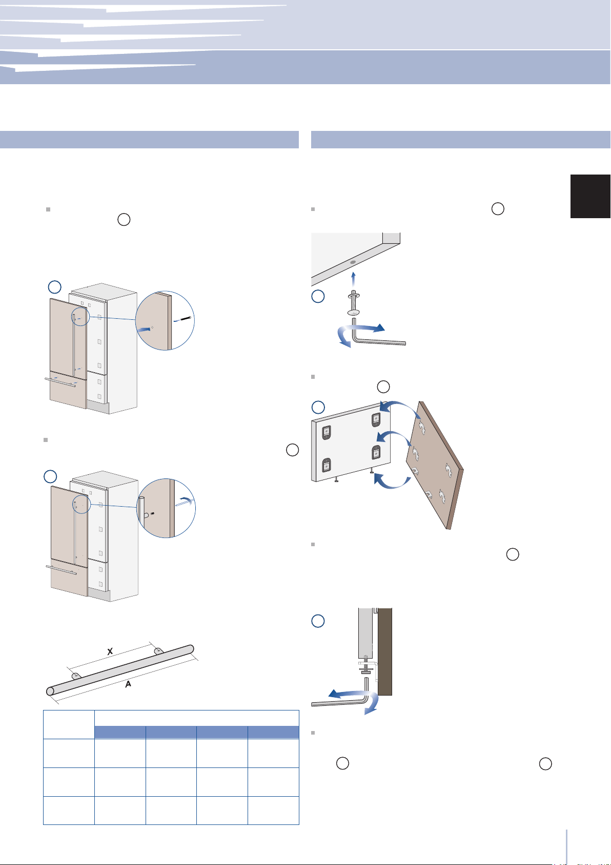
Mounting the handles
Handle product code
Distance
between
xing points X
Series
Lenght
A
Handles will have to be mounted on the panels before
they are applied to the fridge.
Operate as follows:
Drill two holes on the back of the panels according to
the table below
1
.
Place the handle on top of the holes and insert the
screws through the panel and into the handle support
2
.
Mounting panels to the door and the drawer
Once all brackets and small brackets have been applied
to the panels, you can begin installing the bottom drawer.
Operate as follows:
Partially tighten the screw to the xing
1
.
Hook the bottom drawer panel starting from the xings
on the bottom
2
.
It is now possible to align panels to adjacent cabinets in
height using the lower alignment brackets,
3
tightening
or untightening the screws into position as needed. With
the screw slighty tightened, move the panel sideways to
align it to the other panels on the unit or other adjacent
structures.
Depth alignment: working from the inside of the drawer,
after lifting up the magnetic seal, adjust the panel position
so it is closer to or further away from the door using the
holes
4
and then secure the panel using the holes
5
.
58
4
5
6
8
9
7
10
11
2
1
www.fhiaba.com · [email protected] · Tel +39 (0)434 420160 · Fax +39 (0)434 420161
Once the front panel has been adjusted, check that the gasket
has been repositioned correctly to assure the door/drawer
are closing correctly and avoid operational errors of the unit.
Hook the panel to the fixing devices starting from the
top aligning brackets
6
.
At this point, alignment between the panel and ad-
jacent cabinets can be adjusted using the alignment
brackets and small brackets
7
and
8
.
Vertical alignment: tighten or loosen the screw in the
brackets to raise or lower the panel
9
.
Depth alignment: working from the inside of the door,
after lifting up the magnetic seal, adjust the panel posi-
tion so it is closer to or further away from the door using
the holes
10
and then fix the panel in position using the
holes
11
.
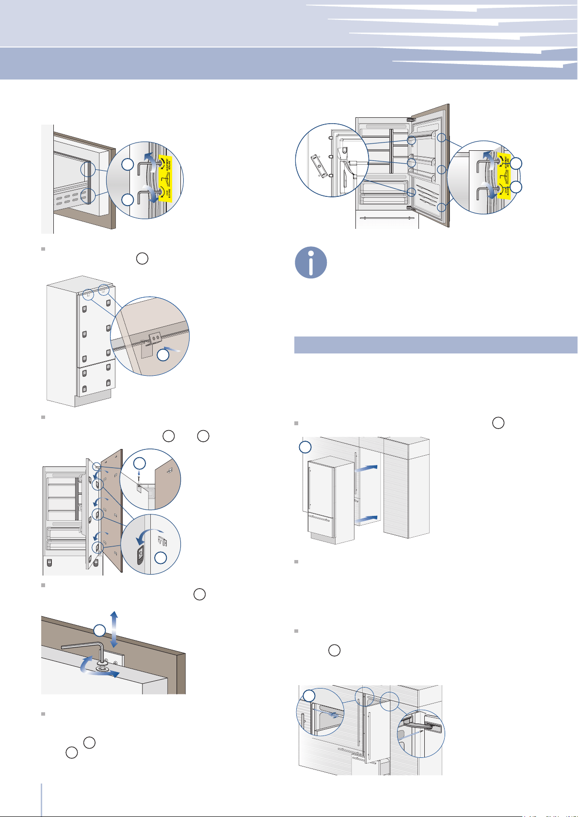
Installation
For a built-in installation, to close gaps between the ap-
pliance and the adjacent cabinets, special side proles
and aluminum covering frames are provided.
Operate as follows:
Push the appliance into the installation niche
1
.
If the unit is to be installed inside a niche or within an
enclosed structure, it is necessary to design a ventilation
shaft at the back of the niche to assure proper ventilation
at the back of the unit. A 5 mm gap is sufcient to prevent
overheating. Always mount front panels on door and dra-
wer before pushing the unit into its nal position inside the
niche or structure.
Secure the appliance to the adjacent cabinets by xing
to these the side proles previously mounted on the ap-
pliance
2
.
To make this operation easier keep the door and the dra-
wer open.
Built-in installation single appliance

59
B
A
6,5 (¼”) 6,5 (¼”)
20 (¾”)
20 (¾”)
22 (7⁄8”)
22 (7⁄8”)
22 (7⁄8”) 22 (7⁄8”)
3
1
2
3
4
5
www.fhiaba.com · [email protected] · Tel +39 (0)434 420160 · Fax +39 (0)434 420161
Installation Guide
EN
ApplianceWall
or
furniture
Wall
or
furniture
A Connecting element
B Alluminium frame
Side proles mounting
Check the levelling of the appliance, adjusting its feet
and wheels to correct it.
Mount the proles the covering frames: rst insert them
laterally and then push rmly until a “click” is heard
3
.
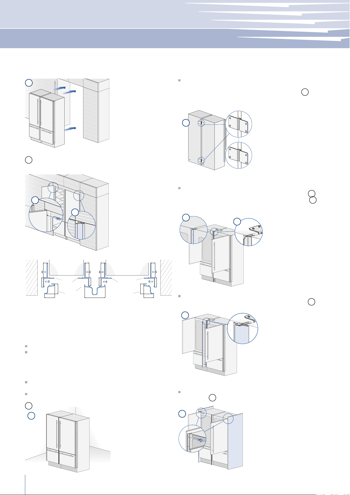
Required accessories to be ordered separately:
Central connection Kit (KCC)
Special side proles and aluminum covering frames are
provided for closing gaps between the appliance and the
adjacent cabinets.
Operate as follows:
Position the appliances in front of the installation area,
leaving enugh space to operate at their back
1
.
Move at the back of the appliances to mount the joining
brackets: x on side of the top and lower brackets to one
of the appliances and subsequently to the other
2
.
Built-in installation two or more appliances
Place the two units side by side and join them at the front
attaching the two pro les with the supplied screws
3
.
Attach the bracket on top of the units as per gure
4
.
Finish off by mounting the central cover frame onto the
central profiles, by pushing it until a click is heard
5
.
Once completed the previous steps, push the units in
their nal position
6
.
If the units are to be installed inside a niche or within an en-
closed structure, it is necessary to design a ventilation shaft
at the back of the niche to assure proper ventilation at the
back of the unit. Always mount front panels on door and
drawer before pushing the unit into its nal position inside
the niche or structure.
Check the levelling of the appliance, adjusting its feet
and wheels to correct it.
Secure the appliance to the adjacent cabinets by xing
to these the side proles previously mounted on the appli-
ance
7
. To make this operation easier keep the door and
the drawer open.
Mount the covering frames onto the proles, rst insert
60
6
8
7
E
D
A
B
A
B
D
6,5 (¼”) 6,5 (¼”)
20 (¾”)
20 (¾”)
22 (7⁄8”)
22 (7⁄8”)
22 (7⁄8”) 22 (7⁄8”)
6,5 (¼”)6,5 (¼”)
18 (¾”)
44,4 (1 ¾”)
18 (¾”)
C
13 (½”)
1
2
3
4
5
7
www.fhiaba.com · [email protected] · Tel +39 (0)434 420160 · Fax +39 (0)434 420161
Appliance Appliance
Wall
or
furniture
Wall
or
furniture
A Connecting element
B Alluminium frame
D Connecting element
E Aluminium frame
Side and central proles mounting
them laterally and then push rmly until a “click” is heard
8
.
Free-standing installation two or more appliances
Required accessories to be ordered separately:
Central Connection Kit (KCC)
Freestanding Kit
Aluminium proles can be used to close the spaces betwe-
en the appliance and adjacent structures.
Operate as follows:
Position the appliances in front of the installation area,
leaving enough space to operate at their back.
Peel off the self adhesive protection and apply the insu-
lated anticondensation panel to the side of one appliance
1
.
Move at the back of the appliances to mount the joining
brackets: x one side of the top and lower brackets to one
of the appliances and subsequently to the other
2
.
Place the two units side by side and join them at the front
attaching the two pro les with the supplied screws
3
.
Attach the bracket on top of the units as per gure
4
.
Finish off by mounting the central cover frame onto the
central profiles, by pushing it until a click is heard
5
.
Attach the side panels to the unit, mounting them on the
side proles
7
pre-mounted on the unit.
61
9
8
H
H
E
D
A
B
A
B
D
6,5 (¼”)6,5 (¼”)
18 (¾”)
44,4 (1 ¾”)
18 (¾”)
6,5 (¼”)
20 (¾”)
22 (7⁄8”)
22 (7⁄8”)
25 (1”)
6,5 (¼”)
20 (¾”)
22 (7⁄8”)
25 (1”)
22 (7⁄8”)
152 (6”)
59 (
2
3⁄8
”)
45 (1
5⁄8
”)
1
2
3
4
www.fhiaba.com · [email protected] · Tel +39 (0)434 420160 · Fax +39 (0)434 420161
Installation Guide
EN
D Central Connection
E Central covering and connection system
G Lateral connecting element
H Side panel
Side panels and central prole mounting
Attach the aluminum cover
8
to each side prole, pres-
sing onto them until they ‘click’ together.
Mount the top panel
9
on top of the unit, using the
screws provided with the kit.
Adjust the height of the unit with the leveling feet and
the back wheels.
Appliance Appliance
To avoid danger of the appliance tipping over it is mandatory
to secure the appliance to the wall by means of two special
brackets.
To prevent the appliance from tipping over an extra-long
kit is vailable up on request if the appliance needs to re-
main distanced from the wall, it is mandatory to install two
brackets on the upper part of the appliance for xing it
securely to the wall.
Operate as follows:
The brackets should be applied as illustrated using the
provided screws and expansion plugs.
Place a bracket on the top of the appliance in correspon-
dence to the xing holes and against the wall
1
.
Anti-tipping safety assembly
Mark up the holes position on the wall
2
.
Drill the wall with an 8 mm (3/8”) bit and insert the expan-
sion plug
3
.
Reposition the bracket and x it rst to the cabinet and
then to the wall
4
.
62
1
2
A
B
C
C
A 860 (33 7⁄8”) 740 (29 1⁄8”)560 (22”)
> 100 (4”)
10 (3⁄8”)
50%
B
C
100 (4”)
www.fhiaba.com · [email protected] · Tel +39 (0)434 420160 · Fax +39 (0)434 420161
Mounting the handles on stainless front
To mount the handles onto the door and the drawer operate
as follows:
Operate as follows:
Insert the two handle spacers onto the supports already
available on the door and the drawer
1
.
Screw in the Allen screws available on the handle
2
.
The screws must be tightened in by means of a 2.5 mm
(1/8”) hex wrench.
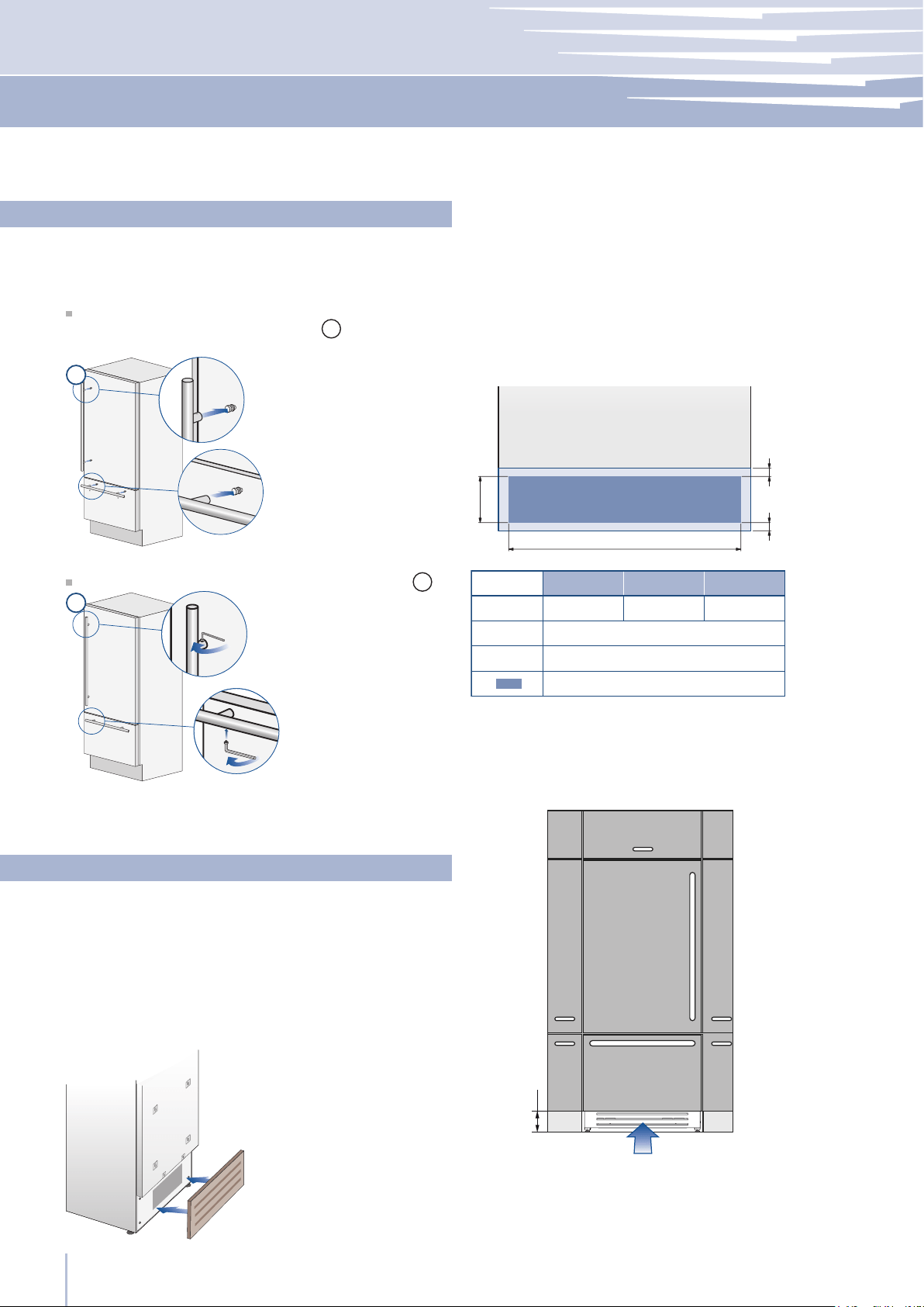
Ventilation
A forced air system assures ventilation through a grille po-
sitioned in the lower front part of the unit. If the kitchen
design includes a kickplate, the latter has to be punched
in order to maintain a satisfactory air ow, as described in
the drawing.
Holes can be in any shape and size, as long as the total
area of the punched part equals 50% of the kickplate are.
In this case, to guarantee a better air ow, it is advisable
to remove the front grille included with the unit. The grille is
secured to the unit with magnetic plates and can be easily
removed even by the end user, to provide for regular clea-
ning procedures and remove dust.
If the grille is partially covered by the kitchen kickplate, it
is advisable to remove the grille in order to provide for a
better airow.
The air intake and outlet must not be blocked or covered
in any way. They also need to be dusted/cleaned on a
regular basis.
Integrated and Classic Series
899 Series 749 Series 599 Series
63
FRIDGE
UNIT
9
3
3.6
CRISPER
10 11 12
11 Display
13 Crisper
12 Up/Down
www.fhiaba.com ∙ www.thevettagroup.com
EnglishFrançais
Before starting
Shows the temperature of the Crisper-Fresco compartment.
Allows switching on and off of only the Crisper-Fresco compartment
(press
for three seconds).
Using the Up and Down buttons, it is possible to change the
temperature set for the Crisper-Fresco compartment.
Crisper-Fresco control panel
8
3
3.5
3.4
1 Unit
2 Fridge
3 Menu
4
Up/down
Fridge
5 Display
6
Up/Down
Freezer
(TriMode)
7 Enter
8 Ice maker
9 Alarm
www.fhiaba.com ∙ www.thevettagroup.com
Before starting
The innovative electronic control system designed by Fhiaba maintains constant temperature in multiple compartments and
displays it on the control panel. It also allows user interaction making it possible to personalize settings of various functions and
to alert the user with sound and/or visual messages should any malfunction occur in the appliance.
Electronic Control
Switches the appliance (all compartments) between ON and STAND BY
(press for three seconds).
Allows switching on and off of only the refrigerator compartment
(press for three seconds).
Allows access to the appliance function menu
It shows the temperature of the refrigerator and freezer compartments,
the date and time, Menu functions and visual messages.
By selecting Up/Down the preset temperature can be changed accord-
ing to the selected function mode (freezer, refrigerator, Crisper-Fresco).
Confirms activation or deactivation of the selections made in the
Menu.
Allows activating or deactivating the automatic ice production.
Blinks to signal user alerts such as door left open, also in combination with
a sound signal which can be deactivated by pressing the button.
Using the Up and Down buttons, it is possible to change the set tempera-
ture of the refrigerator and navigate through the interactive menu.
Main control panel
1234 56798
ICE MAKER
ENTER
FRIDGE
UNIT
www.fhiaba.com · [email protected] · Tel +39 (0)434 420160 · Fax +39 (0)434 420161
Installation Guide
EN
Post installation control
Check that the front levelling feet have been properly
installed.
Check that the connection to the water system does
not have any leaks and that the closing tap is easily ac-
cessible.
Check that the electrical connection is correctly in-
stalled and that the multipole switch and socket are easily
accessible.
Check the perfect alignment of the appliance with
adjacent structures.
Check that all adhesive tape and external or internal
temporary protective devices have been removed.
Check the perfect closing of the doors and the smooth
sliding of the drawers and shelves.
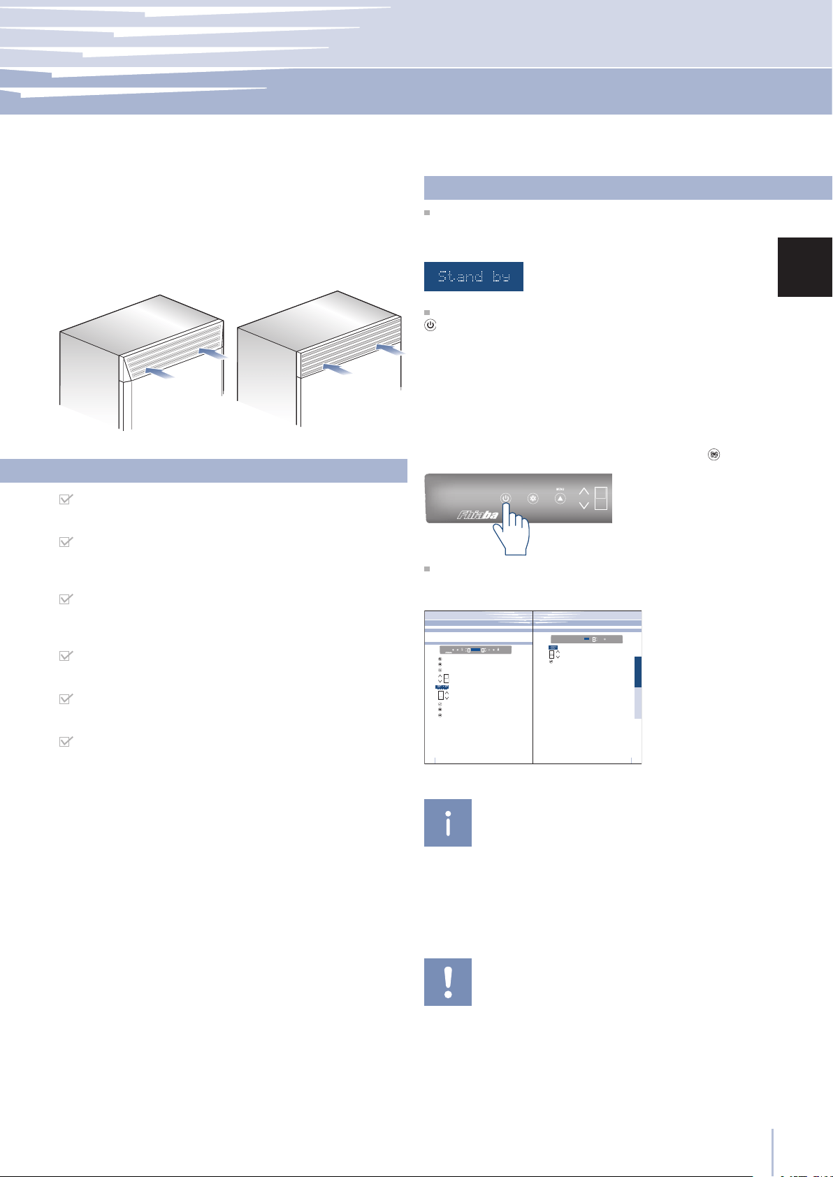
Start up
To start the appliance, connect the plug to the electrical
mains: at this point, when opening the door, the control
panel will usually visualize the message “Stand by”, and all
the panel keys be off
To turn on all the appliance compartments, press the Unit
button for three seconds. The display will show the mes-
sage “Initial test” for approx. 2 minutes. After this phase the
compressors will start up and remain on until the default
temperature set up in the factory is reached. Do bear in
mind that this condition could last several hours. If the ap-
pliance is provided with an Ice Maker, prior to switching it
on make sure that the water lter cartridge is installed, then
ll the water system. To this purpose switch off the Ice Mak-
erand performe a manual clean procedure. At the end
switch the Ice Maker on again by touching the
button.
For further information about the appliance operation,
refer to the User Manual.
Ventilation is insured by a forced air system through a grille
located in the upper part of the appliance.
This grille should never be covered by panels or any other
devices that could reduce its efciency.
Please refer to page 5-6 to ensure correct air circulation.
StandPlus and X-Pro Series
If at the rst start - up the message Stand by does not ap-
pear, but other messages appear, such as Fridge too warm,
Fresco too warm, Freezer too warm, or sound signals are ac-
tivated, it means that the appliance has already started the
cooling process. If this is the case, deactivate any possible
acoustic signals by pressing the Alarm button, close the door
and wait until the set temperature is reached.
It is necessary to let the unit reach the correct temperature
before foods are stored inside.

Fhiaba srl Via Fiumicino, 20 · 33082 · Azzano Decimo · PN · Italy · Tel +39 0434 420160 · Fax +39 0434 420161
E-mail: [email protected] · www.fhiaba.com · Info Line 800-Fhiaba (800-344222)
24-08-2016
Baron Industries srl is constantly researching new way to improve the features
and the design of their products, therefore models are often upgraded and
reviewed.
B09000704 A