OPERATOR'S MAN UAL
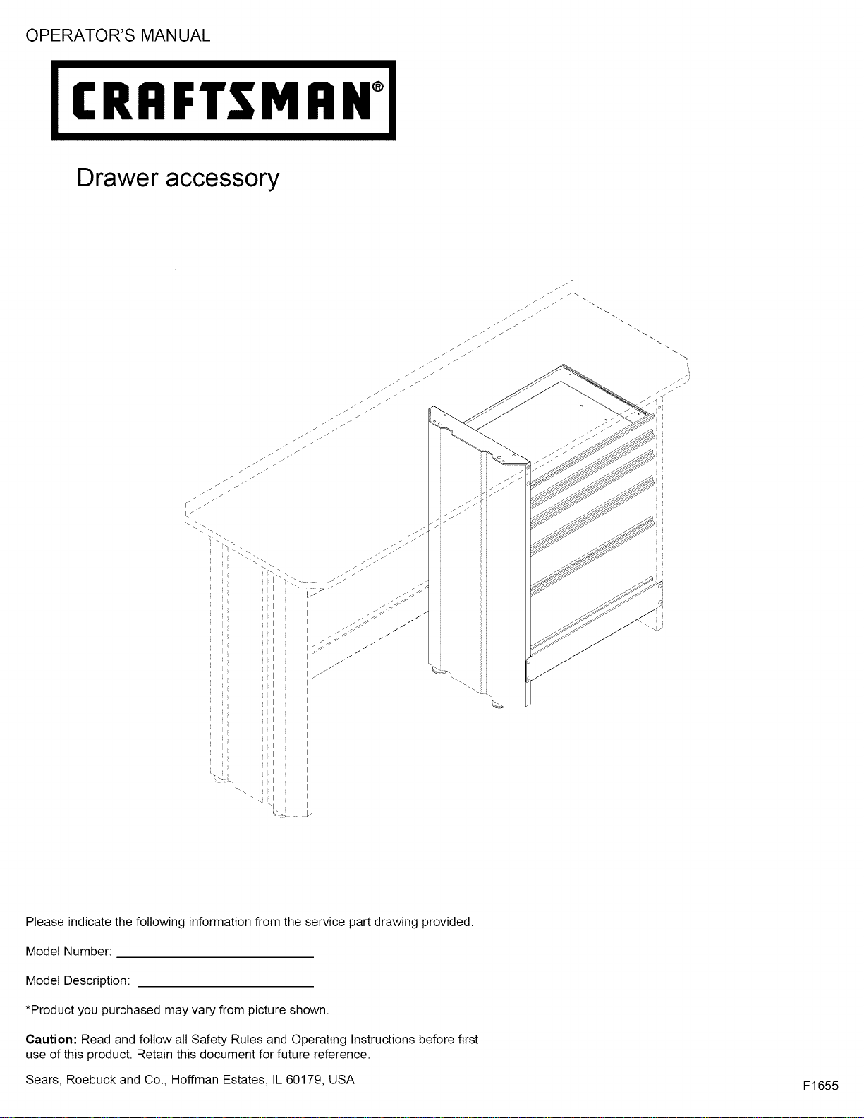
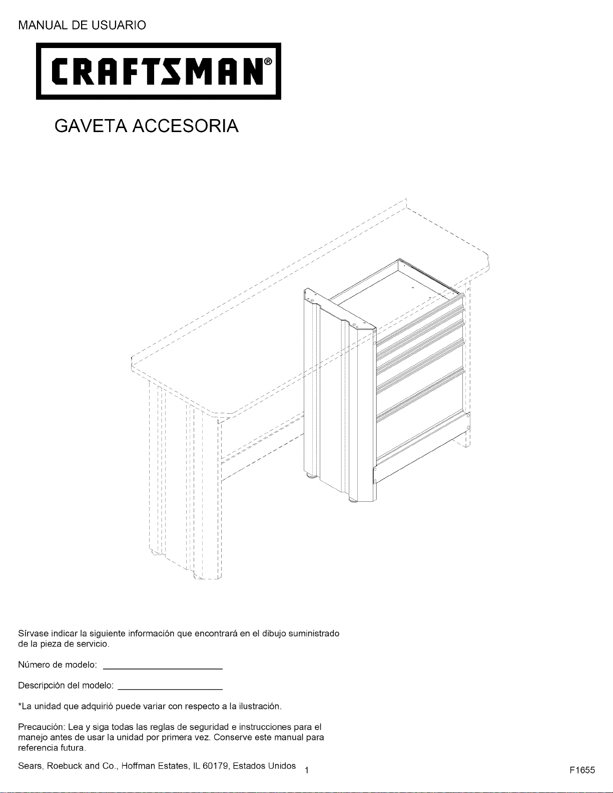
Drawer accessory
I
i I
I
I
I
i I
I
I
Please indicate the following information from the service part drawing provided.
Model Number:
Model Description:
*Product you purchased may vary from picture shown.
Caution: Read and follow all Safety Rules and Operating Instructions before first
use of this product. Retain this document for future reference.
Sears, Roebuck and Co., Hoffman Estates, IL 60179, USA
F1655

f
SAFETY WARNINGS AND CAUTIONS:
• Use appropriate safety equipment when using power and hand tools. Failure to do so may cause personal injury or product
damage.
• Use adequate manpower when assembling and moving this unit. Failure to do so may cause personal injury or product
damage.
• DO NOT stand on this product. You may fall which may cause personal injury.
• DO NOT mount this product on a truck bed or any other moving object. This may cause personal injury or product damage.
• Appropriately secure this product before moving it with a forklift.
• DO NOT alter this product in any manner. For example, do not weld external Iockbars or attach electrical equipment. This
may cause product damage or personal injury.
• Keep the product on level surfaces. The product may become unstable and tip if stored or moved on an un-level surface,
which may cause personal injury or product damage.
• BE CAREFUL when opening more than one drawer. The product may become unstable and tip, which may cause personal
injury or product damage.
• DO NOT step in the drawers. You may fall which may cause personal injury.
• Maximum weight for each drawer should be no more than (35) pounds.
k,.
.)
Tools Required:
Socket wrench
7/16" socket
11/32" wrench
Screwdriver, crosstip
Screwdriver, flathead
Square
Hardware Included
AA(10)
,,m
BB(10)
'i
cc(10)
DD(20)
EE(20)
FF(20)
A
/
/J
/
G (10)
GG(2)
ii
Call 1-800-4MY-HOME (1-800-469-4663) for Service Parts.
efer to Service Parts Drawing for full listing of Service Parts.
r
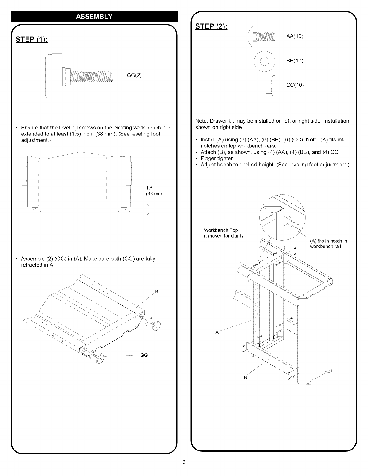
STEP (1):
GG(2)
I
Ensure that the leveling screws on the existing work bench are
extended to at least (1.5) inch, (38 mm). (See leveling foot
adjustment.)
1.5"
(38 mm)
• Assemble (2) (GG) in (A). Make sure both (GG) are fully
retracted in A.
_11111
f
STEP (2):
"\ i
/
AA(10)
BB(10)
CC(10)
Note: Drawer kit may be installed on left or right side. Installation
shown on right side.
• Install (A) using (6) (AA), (6) (BB), (6) (CC). Note: (A) fits into
notches on top workbench rails.
• Attach (B), as shown, using (4) (AA), (4) (BB), and (4) CC.
• Finger tighten.
• Adjust bench to desired height. (See leveling foot adjustment.)
Workbench Top
removed for clarity
(A) fits in notch in
workbench rail
B
.)
r
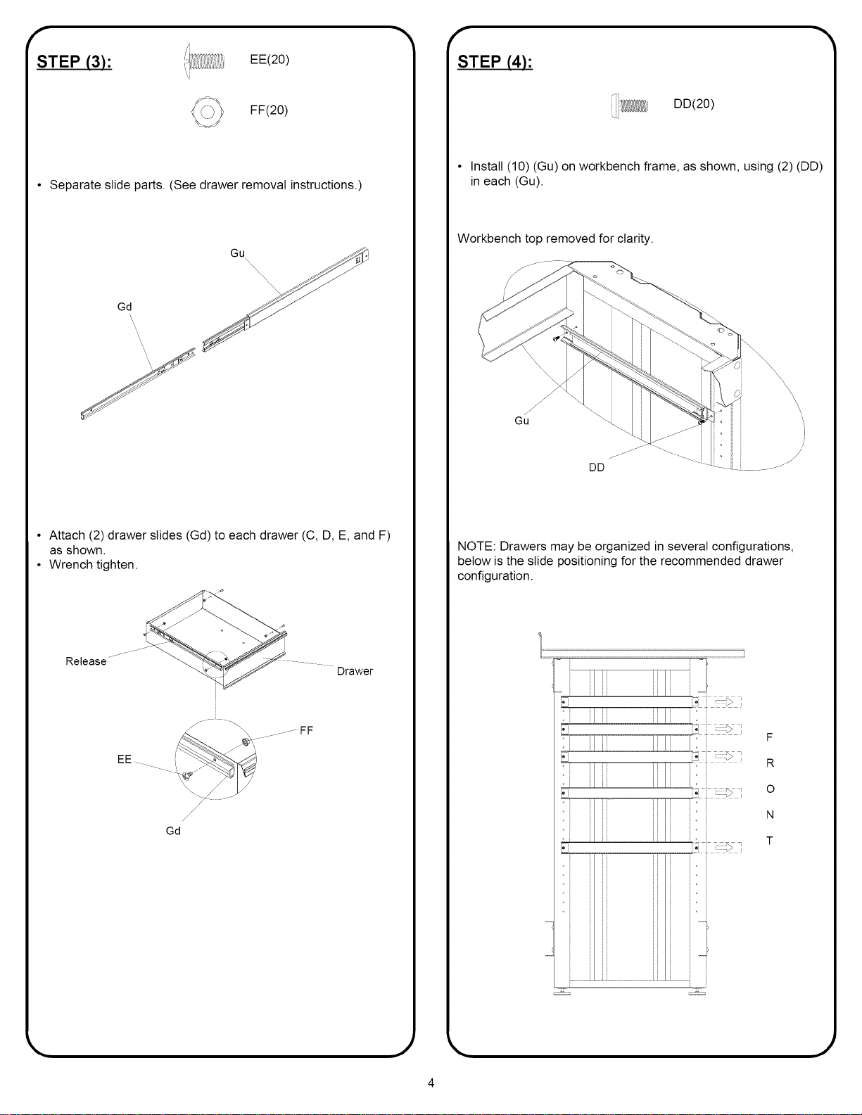
STEP (3):
EE(20)
FF(20)
• Separate slide parts. (See drawer removal instructions.)
Gd
Gu
• Attach (2) drawer slides (Gd) to each drawer (C, D, E, and F)
as shown.
• Wrench tighten.
Release
Drawer
.........FF
EE i_ .....
/
/
/
Gd
f
STEP (4):
DD(20)
• Install (10) (Gu) on workbench frame, as shown, using (2) (DD)
in each (Gu).
Workbench top removed for clarity.
NOTE: Drawers may be organized in several configurations,
below is the slide positioning for the recommended drawer
configuration.
...... ii
F
R
0
N
T
,.)
r
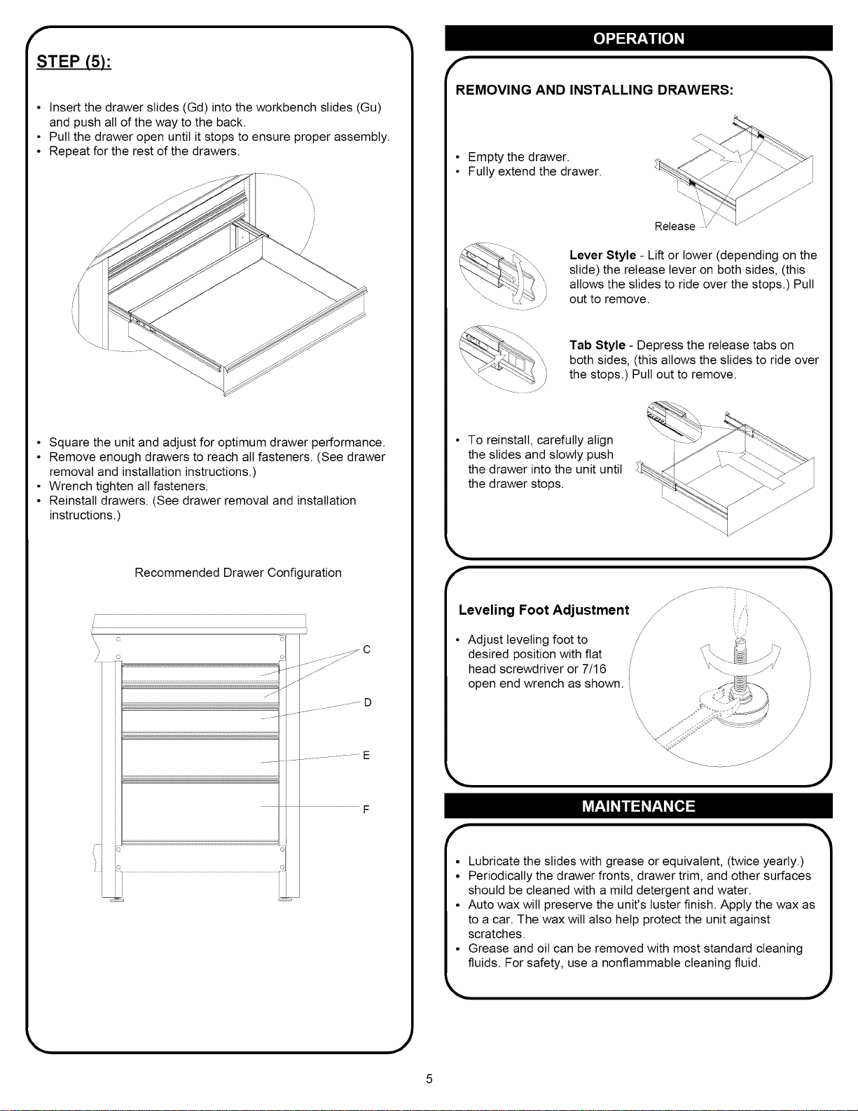
STEP (5):
• Insert the drawer slides (Gd) into the workbench slides (Gu)
and push all of the way to the back.
• Pull the drawer open until it stops to ensure proper assembly.
• Repeat for the rest of the drawers.
'i
/
/
/
/
• Square the unit and adjust for optimum drawer performance.
• Remove enough drawers to reach all fasteners. (See drawer
removal and installation instructions.)
• Wrench tighten all fasteners.
• Reinstall drawers. (See drawer removal and installation
instructions.)
Recommended Drawer Configuration
o
\
_11111
f
REMOVING AND INSTALLING DRAWERS:
• Empty the drawer.
• Fully extend the drawer.
Release :_/
Lever Style - Lift or lower (depending on the
slide) the release lever on both sides, (this
allows the slides to ride over the stops.) Pull
out to remove.
Tab Style - Depress the release tabs on
both sides, (this allows the slides to ride over
the stops.) Pull out to remove.
• To reinstall, carefully align
the slides and slowly push
the drawer into the unit until
the drawer stops.
f
Leveling Foot Adjustment
• Adjust leveling foot to
/
desired position with flat
head screwdriver or 7/16
open end wrench as shown. I
f i ,.!_ _'.\
/
//
/
,J
f
• Lubricate the slides with grease or equivalent, (twice yearly.)
• Periodically the drawer fronts, drawer trim, and other surfaces
should be cleaned with a mild detergent and water.
• Auto wax wilt preserve the unit's luster finish. Apply the wax as
to a car. The wax will also help protect the unit against
scratches.
• Grease and oil can be removed with most standard cleaning
fluids. For safety, use a nonflammable cleaning fluid.
J

MANUAL DE USUARIO
I(r FT M""°I
GAVETA ACCESORIA
/
f
J
!/
iil
iil
iil
\\.iil
..........L)
\
Sirvase indicar ta siguiente informaci6n que encontrara en el dibujo suministrado
de la pieza de servicio.
Nemero de modelo:
Descripci6n del modelo:
*La unidad que adquiri6 puede variar con respecto a la ilustraci6n.
Precauci6n: Lea y siga todas tas regtas de seguridad e instrucciones para el
manejo antes de usar la unidad por primera vez. Conserve este manual para
referencia futura.
Sears, Roebuck and Co., Hoffman Estates, IL 60179, Estados Unidos 1
F1655
ADVERTENCIAS Y PRECAUCIONES DE SEGURIDAD:
r
• Utitice el equipo de seguridad adecuado cuando emptee herramientas electricas. De 1ocontrario, podria causarle lesiones personales u
ocasionar daSos al producto.
• Utitice el personal adecuado para el montaje y el traslado de esta unidad. De lo contrario podria ocasionarse lesiones personales o daSar
el producto.
• NO se ponga de pie sobre ta unidad. Podria caerse y tesionarse.
• NO monte esta unidad en la plataforma de carga de la camioneta ni en ning0n otro objeto m6vil. Podria causar lesiones personales o
daSo a la unidad.
• Asegure adecuadamente ta unidad antes de moverla con un montacargas.
• NO altere ta unidad en modo alguno. Por ejemplo, no suelde las barras de sujeci6n externas nile incorpore equipos electricos. Podria
causar daSo a la unidad o tesiones personales.
• Mantenga el producto sobre superficies planas. Et producto puede desestabilizarse y volcar si se almacena o se mueve en superficies no
ltanas, to cual podria causar tesiones personales o daSar el producto.
• SEA CUlDADOSO cuando abra mas de una gaveta. Las unidades podrian quedar inestables y volcarse, 1ocual podria ocasional lesiones
personales o daSo a la unidad.
• NO se ponga de pie en las gavetas. Podria caerse y lesionarse.
• El peso maximo para cada caj6n no deberia ser superior a (35) libras ((15,9) kilos.
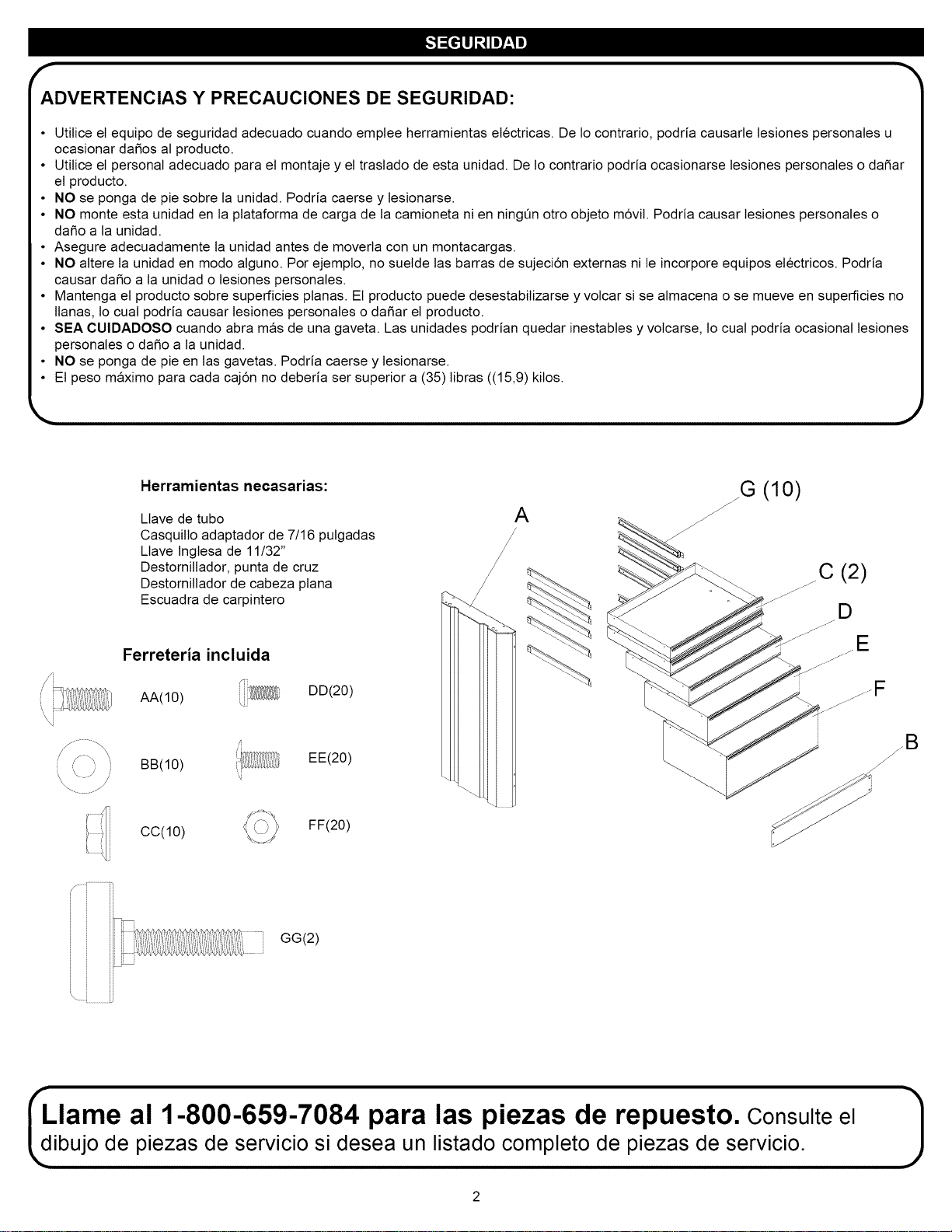
Herramientas necasarias:
Ltave de tubo
Casquillo adaptador de 7/16 pulgadas
Ltave Ingtesa de 11/32"
Destornittador, punta de cruz
Destorniltador de cabeza plana
Escuadra de carpintero
Ferreteria incluida
AA(10)
DD(20)
BB(10)
,,i
'i
EE(20)
cc(10)
FF(20)
A
/
/J
/
G (10)
GG(2)
ii
Llame al 1-800-659-7084 para las piezas de repuesto. Consulte el
bujo de piezas de servicio si desea un listado completo de piezas de servicio.
r
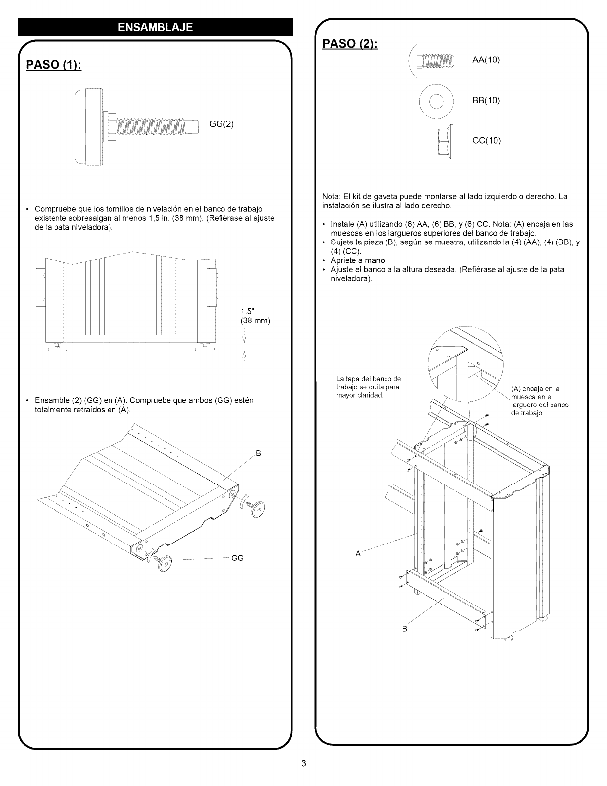
PASO (1):
GG(2)
I
• Compruebe que los tomillos de nivelaci6n en el banco de trabajo
existente sobresalgan al menos 1,5 in. (38 mm). (Refierase al ajuste
de la pata niveladora).
• Ensamble (2) (GG) en (A). Compruebe que ambos (GG) esten
totalmente retraidos en (A).
_llll
PASO (2):
AA(10)
BB(10)
/
\-. J
CC(10)
Nota: El kit de gaveta puede montarse al lado izquierdo o derecho. La
instalaci6n se ilustra al lado derecho.
• Instale (A) utilizando (6) AA, (6) BB, y (6) CC. Nota: (A) encaja en las
muescas en los largueros superiores del banco de trabajo.
• Sujete la pieza (B), segOn se muestra, utilizando la (4) (AA), (4) (BB), y
(4) (CC).
• Apriete a mano.
• Ajuste el banco a la altura deseada. (Refierase al ajuste de la pata
niveladora).
La tapa del banco de
trabajo se quita para
mayor claridad.
(A) encaja en la
\_ muesca en el
larguero del banco
de trabajo
.)
r
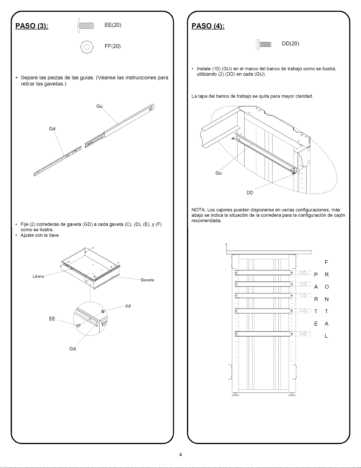
PASO (3):
EE(20)
FF(20)
• Separe tas piezas de las guias. (Veanse las instrucciones para
retirar las gavetas.)
Gd
Gu
• Fije (2) correderas de gaveta (GD) a cada gaveta (C), (D), (E), y (F)
como se ilustra.
• Ajuste con la Ilave.
Libere
Gaveta
.........FF
EE .....
/
/
/
Gd
f
PASO (4):
DD(20)
• Instale (10) (GU) en el marco del banco de trabajo como se ilustra,
utilizando (2) (DD) en cada (GU).
La tapa del banco de trabajo se quita para mayor claridad.
NOTA: Los cajones pueden disponerse en varias configuraciones, mas
abajo se indica la situaci6n de la corredera para la configuraci6n de caj6n
recomendada.
i,; , , p
ili i I i:
i' ....:?I A
R
......... T
E
F
R
O
N
T
A
L
.)
r
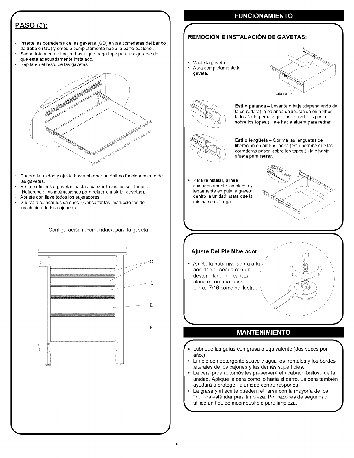
PASO (5):
• Inserte las correderas de las gavetas (GD) en las correderas del banco
de trabajo (GU) y empuje completamente hacia la parte posterior.
• Saque totalmente el caj6n hasta que haga tope para asegurarse de
que esta adecuadamente instalado.
• Repita en el resto de las gavetas.
• Cuadre la unidad y ajuste hasta obtener un 6ptimo funcionamiento de
las gavetas.
• Retire suficientes gavetas hasta alcanzar todos los sujetadores.
(Refierase alas instrucciones para retirar e instalar gavetas).
• Apriete con Ilave todos los sujetadores.
• Vuelva a colocar los cajones. (Consultar las instrucciones de
instalaci6n de los cajones.)
Configuraci6n recomendada para la gaveta
1
_-_ C
_f J_
............ D
F
f
REMOCION E INSTALACION DE GAVETAS:
• Vacie la gaveta.
• Abra completamente la
gaveta.
Libere i/
Estilo palanca - Levante o baje (dependiendo de
la corredera) la palanca de liberaci6n en ambos
lados (esto permite que las correderas pasen
sobre los topes.) Hale hacia afuera para retirar.
Estilo lengiJeta - Oprima las lengQetas de
liberaci6n en ambos lados (esto permite que las
correderas pasen sobre los topes.) Hale hacia
afuera para retirar.
Para reinstalar, alinee
cuidadosamente las placas y
lentamente empuje la gaveta
dentro la unidad hasta que la
misma se detenga.
f
Ajuste Del Pie Nivelador
• Ajuste ta pata niveladora a la /
/
posici6n deseada con un
destornillador de cabeza
plana o con una ltave de
tuerca 7/16 como se ilustra. "',
,\
/. ............... _ _ .
(/) \
x J
/
/
/
.)
• Lubrique las guias con grasa o equivalente (dos veces por
afio.)
• Limpie con detergente suave y agua los frontales y los bordes
laterales de los cajones y tas demas superficies.
• La cera para autom6vites preservara el acabado brilloso de ta
unidad. Aplique ta cera como to haria al carro. La cera tambien
ayudara a proteger ta unidad contra raspones.
• La grasa y el aceite pueden retirarse con la mayoria de los
liquidos estandar para limpieza. Por razones de seguridad,
_,utitice un liquido incombustible para limpieza. ,j