Owner’s Manual
USING THE UNIT SAFELY ............................ 2
IMPORTANT NOTES ................................. 2
How the RC-600 Is Organized ....................... 3
Getting Ready ....................................... 4
Top Panel ............................................. 4
Rear Panel (Connecting Your Equipment) ................ 7
Turning the Power On/O .............................. 7
Phantom Power Settings ............................... 7
Switching Between Play Screens ........................ 8
Adjusting the Input/Output Level ....................... 8
Pedal Mode ........................................... 9
Creating a Loop Phrase ............................. 10
Recording on a Single Track. . . . . . . . . . . . . . . . . . . . . . . . . . . . . 10
Recording on Multiple Tracks ........................... 11
Record While Listening to the Rhythm Sound ............ 12
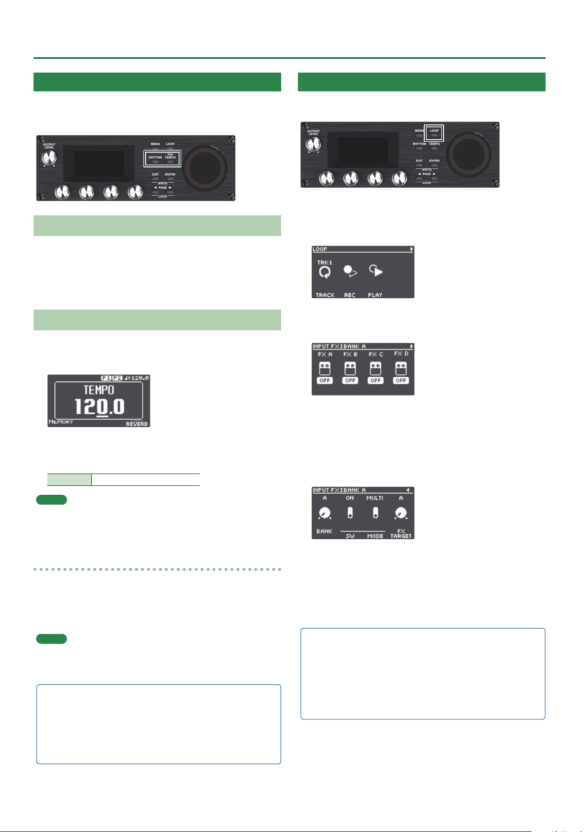
Sounding a Rhythm ..................................... 12
Setting the Tempo of Rhythm ............................. 12
Using the Input FX ..................................... 12
Saving a Memory .................................... 13
Saving a Memory (WRITE) .............................. 13
Erasing Data from a Memory (CLEAR) .................... 13
Editing a Memory ................................... 14
Editing the Settings of a Memory ....................... 14
Editing the Track Settings .............................. 15
Editing the Rhythm Settings ............................ 16
Changing How the Rhythm Starts and Stops ................. 16
Editing the Input FX/Track FX Settings ................... 17
System Settings (MENU) ............................ 18
Connecting to a Computer via USB ................. 20
Backing Up or Recovering Data ......................... 20
Controlling Devices via MIDI
........................... 21
MIDI Settings .......................................... 21
Controlling an External MIDI Device from the RC-600 .......... 21
Controlling the RC-600 from an External MIDI Device .......... 22
Connecting Two RC-600 Units ........................... 22
Appendix ............................................ 23
Troubleshooting ....................................... 23
Error Message List ..................................... 24
Restoring the Factory Default Settings (Factory Reset) .... 25
Main Specications .................................... 26
Owner’s Manual (this document)
Read this rst. It explains the basic things you need to know in order to
use the RC-600.
Parameter Guide (download from the Web)
This explains all of the parameters of the RC-600.
Before using this unit, carefully read “USING THE UNIT SAFELY” and “IMPORTANT NOTES” (the leaet “USING THE UNIT SAFELY” and the
Owner’s Manual (p. 2)). After reading, keep the document(s) where it will be available for immediate reference.
© 2021 Roland Corporation
To obtain the Parameter Guide
1. Enter the following URL on your computer.
https://www.boss.info/manuals/
2. Choose “RC-600” as the product name.
2
IMPORTANT NOTES
Power Supply
• Place the AC adaptor so the side with the indicator faces upwards. The indicator will
light when you plug the AC adaptor into an AC outlet.
• Depending on the material and temperature of the surface on which you place the
unit, its rubber feet may discolor or mar the surface.
Repairs and Data
• Before sending the unit away for repairs, be sure to make a backup of the data
stored within it; or you may prefer to write down the needed information. Although
we will do our utmost to preserve the data stored in your unit when we carry out
repairs, in some cases, such as when the memory section is physically damaged,
restoration of the stored content may be impossible. Roland assumes no liability
concerning the restoration of any stored content that has been lost.
Additional Precautions
• Any data stored within the unit can be lost as the result of equipment failure,
incorrect operation, etc. To protect yourself against the irretrievable loss of data, try
to make a habit of creating regular backups of the data you’ve stored in the unit.
• Roland assumes no liability concerning the restoration of any stored content that
has been lost.
• Never strike or apply strong pressure to the display.
• When disposing of the packing carton or cushioning material in which this unit was
packed, you must observe the waste disposal regulations that apply to your locality.
• Use only the specied expression pedal (FV-500H, FV-500L, EV-30, and Roland
EV-5; sold separately). By connecting any other expression pedals, you risk causing
malfunction and/or damage to the unit.
• Do not use connection cables that contain a built-in resistor.
Intellectual Property Right
• It is forbidden by law to make an audio recording, video recording, copy or revision
of a third party’s copyrighted work (musical work, video work, broadcast, live
performance, or other work), whether in whole or in part, and distribute, sell, lease,
perform or broadcast it without the permission of the copyright owner.
• Do not use this product for purposes that could infringe on a copyright held
by a third party. We assume no responsibility whatsoever with regard to any
infringements of third-party copyrights arising through your use of this product.
• The copyright of content in this product (the sound waveform data, style data,
accompaniment patterns, phrase data, audio loops and image data) is reserved by
Roland Corporation.
• Purchasers of this product are permitted to utilize said content (except song data
such as Demo Songs) for the creating, performing, recording and distributing
original musical works.
• Purchasers of this product are NOT permitted to extract said content in original or
modied form, for the purpose of distributing recorded medium of said content or
making them available on a computer network.
• This product contains eParts integrated software platform of eSOL Co., Ltd. eParts is
a trademark of eSOL Co., Ltd. in Japan.
• This Product uses the Source Code of μT-Kernel under T-License 2.0 granted by the
T-Engine Forum (www.tron.org).
• This product includes third party open source software.
Copyright © 2009-2019 ARM Limited. All rights reserved.
Licensed under the Apache License, Version 2.0 (the “License”);
You may obtain a copy of the License at
http://www.apache.org/licenses/LICENSE-2.0
Copyright © 2016, Freescale Semiconductor, Inc.
Copyright 2016-2019 NXP. All rights reserved.
Licensed under the BSD-3-Clause;
You may obtain a copy of the License at
https://opensource.org/licenses/BSD-3-Clause
Copyright © 2020 Amazon.com, Inc. or its aliates. All Rights Reserved.
Licensed under the MIT license
https://opensource.org/licenses/mit-license.php
• Roland, BOSS, and LOOP STATION are either registered trademarks or trademarks of
Roland Corporation in the United States and/or other countries.
• Company names and product names appearing in this document are registered
trademarks or trademarks of their respective owners.
WARNING
Concerning the Auto O function
The power to this unit will be turned o
automatically after a predetermined amount
of time has passed since it was last used for
playing music, or its buttons or controls were
operated (AUTO OFF function). If you do not want the
power to be turned o automatically, disengage the
AUTO OFF function (p. 19).
WARNING
Use only the supplied AC adaptor and the correct
voltage
Be sure to use only the AC adaptor supplied
with the unit. Also, make sure the line voltage
at the installation matches the input voltage
specied on the AC adaptor’s body. Other AC
adaptors may use a dierent polarity, or be designed
for a dierent voltage, so their use could result in
damage, malfunction, or electric shock.
Use only the supplied power cord
Use only the attached power cord. Also, the
supplied power cord must not be used with
any other device.
CAUTION
Handle the ground terminal carefully
If you remove the screw from the ground
terminal, be sure to replace it; don’t leave
it lying around where it could accidentally
be swallowed by small children. When
refastening the screw, make that it is rmly fastened,
so it won’t come loose.
Precautions concerning use of phantom power
supply
Always turn the phantom power o when
connecting any device other than condenser
microphones that require phantom power.
You risk causing damage if you mistakenly
supply phantom power to dynamic microphones,
audio playback devices, or other devices that don’t
require such power. Be sure to check the specications
of any microphone you intend to use by referring
to the manual that came with it. (This instrument’s
phantom power: 48 V DC, 10 mA Max)
USING THE UNIT SAFELY

3
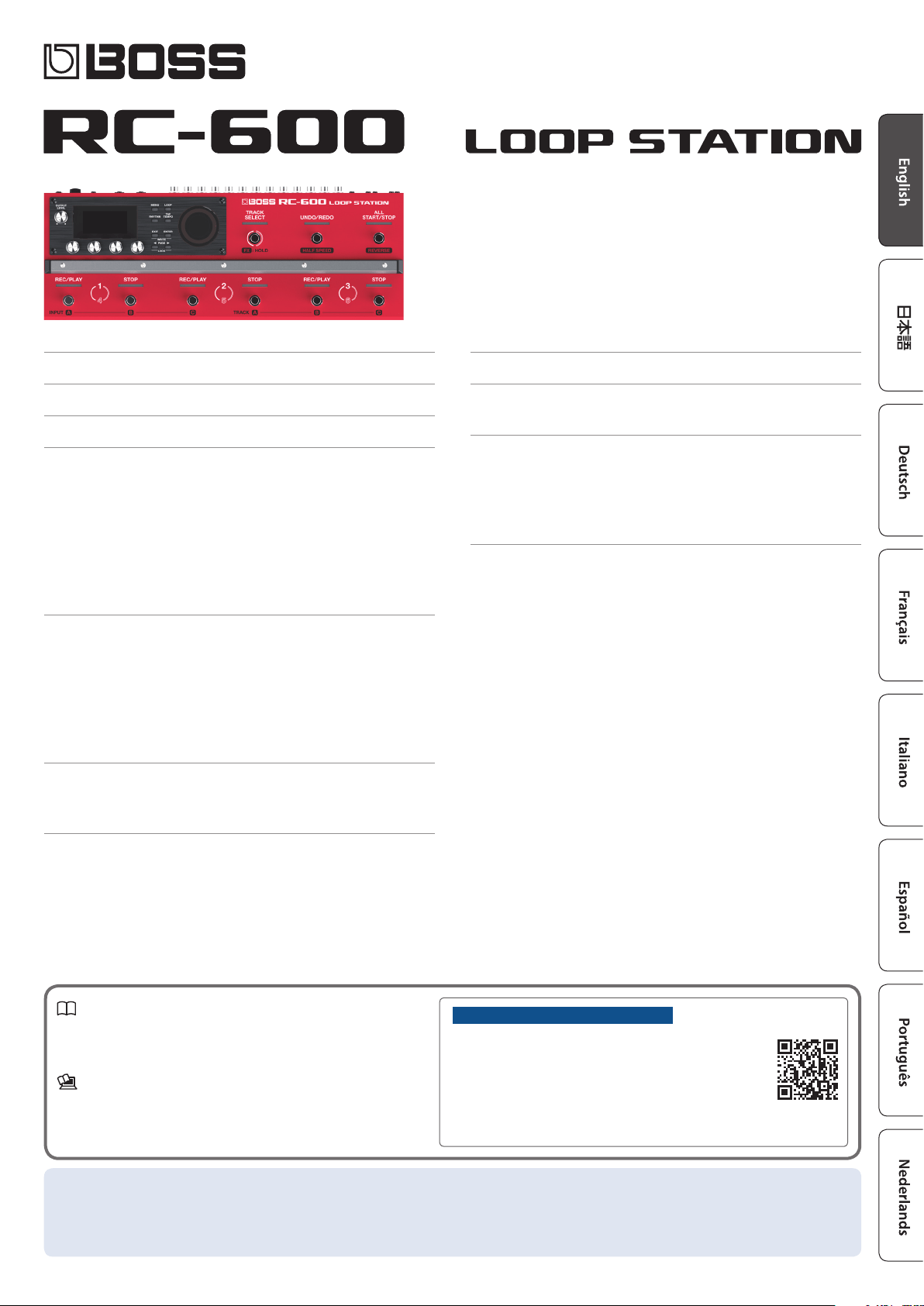
How the RC-600 Is Organized
Track
Tracks are used for recording and playing back audio from a
microphone or a musical instrument.
You can combine tracks 1–6 when using this unit.
Input FX, Track FX
Eects that are applied to the input audio are called “input FX”,
and eects that are applied to the tracks are called “track FX”.
You can register 16 input/track FX (4 banks x 4 types) to the
buttons and use them.
Rhythm
In addition to playing back tracks 1–6, you can also play rhythms
with this unit.
You can record while listening to a rhythm at the tempo you
specify.
Memory
The settings for tracks 1–6 together with the input FX/track FX and
rhythm are collectively called a “memory”.
You can store up to 99 memories with this unit.
System settings
Settings that are common to the RC-600 overall such as the
display contrast, USB and MIDI settings are called “system
settings”.
Memory 99
Memory 01
Rhythm
System settings
Track 1
Track 2
Track 3
Track 4
Track 5
Input FX
Banks A–D
FX
Track FX
Banks A–D
FX
Track 6
“Recording” versus “Overdubbing”
In this manual, we refer to the act of recording to an empty track for the rst time as “recording”. Any subsequent recordings that are
made, which are added on top of the existing recording, we refer to as “overdubbning”.

4
Getting Ready
1
[OUTPUT LEVEL] knob
Adjusts the volume of the RC-600.
Display
Shows various information of the RC-600.
[1]–[4] knobs
Use these knobs to set the parameter values shown in the screen.
[1] [2] [3] [4]
5 To change a value in larger steps, turn a knob while pressing it.
5 For some parameters, you must press the knob to edit the
value.
2
[MENU] button
This button gives you access to the overall system settings and
USB/MIDI settings of the RC-600.
[LOOP] button
Press this button to edit a memory.
Use this to congure the settings for tracks 1–6, settings related
to loop playback/recording and so on, input FX/track FX settings,
rhythm settings and the memory name.
[RHYTHM] button
Each time you press the button, the rhythm switches on (lit)/o
(unlit)/standby (blink).
[TAP TEMPO] button
Set the tempo by pressing this button at the desired interval
(tap tempo). When doing this, the tempo is shown on the screen.
Long-press the button to return to the previous tempo.
3
[EXIT] button
Press to return to the previous screen.
[ENTER] button
Press to conrm an operation.
5 If you press the [ENTER] button while the play screen is
shown, the screen switches to the MIXER screen (p. 8).
5 By pressing the [EXIT] button and [ENTER] button
simultaneously, you can save a memory (write) or erase
(clear) memory data.
PAGE [
K
] [
J
] buttons
Use these buttons to move the cursor and switch between pages.
If you press these buttons while the play screen is shown, you can
switch between variations of the play screen.
LOCK function
In the play screen, press the PAGE [K] [J] buttons simultaneously
to turn the lock function on, so that the [1]–[4] knobs are
disabled. This lets you prevent the settings from being changed
inadvertently.
The Lock function turns o when you press the two buttons
simultaneously once again.
4
Loop indicators
Indicates the track’s status and loop position.
Top Panel
1
4
2
3
5
6

5
Getting Ready
5
[TRACK SELECT] switch/indicator
Switches between tracks 1–3 and 4–6.
Indicator Explanation
Lit white Tracks 1–3
Lit red Tracks 4–6
When you hold down the [TRACK SELECT] switch, the indicator
lights up blue, and the switches on this unit change their functions.
[UNDO/REDO] switch/indicator
Press the switch during playback or overdubbing to cancel the
recording or the last overdubbing (Undo).
Press the switch once again to cancel the Undo (Redo).
Indicator Explanation
Lit green Undo available
Lit red Redo available
Unlit Undo/redo not available
TRACK SELECT indicator: when lit blue
The [UNDO/REDO] switch/indicator functions as the [HALF SPEED]
switch/indicator. This is used to switch between playback speeds
for the currently selected track (current track).
Indicator Explanation
Lit 1/2 playback speed
Unlit Normal playback speed
MEMO
The track that is currently selected (currently the target of
operations) is called the “current track”.
[ALL START/STOP] switch/indicator
This makes all tracks start (play back) at the same time.
If you press this button when the tracks are currently playing back
or recording, all tracks stop.
TRACK SELECT indicator: when lit blue
The [ALL START/STOP] switch/indicator functions as the [REVERSE]
switch/indicator. This is used to switch between normal and reverse
playback for the currently selected track (current track).
Indicator Explanation
Lit Reverse playback
Unlit Normal playback
6
[REC/PLAY] 1–6 switches/indicators
Switches between recording, playback, and overdubbing.
For an empty phrase:
Recording0Playback0Overdubbing
For a phrase that contains data:
Playback0Overdubbing
Indicator Explanation
Lit blue
No phrase
Lit red
Recording
Lit green
Playing
Lit yellow
Overdubbing
Lit white Stopping (phrase exists)
[STOP] 1–6 switches/indicators
Stops the track that is currently recording/playing/overdubbing.
If you long-press the switch (two seconds or longer), the track is
cleared.
Indicator Explanation
Lit blue No phrase
Lit white Phrase exists
TRACK SELECT indicator: when lit blue
These function as the INPUT [A]–[C] switches/indicators and the
TRACK [A]–[C] switches/indicators.
INPUT [A]–[C] switches/indicators
Switches the eects A–C in the currently selected input FX bank
on/o.
TRACK [A]–[C] switches/indicators
Switches the eects A–C in the currently selected track FX bank on/
o.
Indicator Explanation
Lit red Eect: on
Lit pink Indicates the eect you can currently operate/edit (eect: on).
Unlit Eect: o
Top Panel

6
Getting Ready
7
MIC IN 1, 2 connectors
Connect your microphone(s) here.
* If you’re using a condenser mic that requires phantom power, turn
on this unit’s phantom power.
INST IN 1, 2 jacks (L/MONO, R)
Connect your guitar/bass, eect units, keyboards and other
instruments to these jacks.
8
MAIN OUTPUT jacks (L/MONO, R)
SUB OUTPUT 1, 2 jacks (L/MONO, R)
Connect these jacks to your amp, monitor speakers or mixer.
MEMO
You can set the MAIN/SUB jacks as parallel output jacks
(mono output x 6) that individually output the sounds from each
track.
& “Parameter Guide” (PDF)
PHONES jack
Connect your headphones here.
MEMO
You can congure this unit to let you listen to only the audio you
specify in headphones.
& “Parameter Guide” (PDF)
9
CTL/EXP
CTL 1, 2/EXP 1 jack and CTL 3, 4/EXP 2 jack
You can connect an expression pedal or footswitches
(sold separately) to these jacks, for controlling a variety of
functions.
* Use only the specied expression pedal (FV-500H, FV-500L, EV-
30, and Roland EV-5; sold separately). By connecting any other
expression pedals, you risk causing malfunction and/or damage
to the unit.
10
MIDI OUT, MIDI IN connectors
Connect an external MIDI device here.
This lets you control an external MIDI device from this unit via
MIDI.
11
USB port
Connect your computer using a commercially available USB cable
that supports USB 2.0.
You can connect your computer here and use it to back up or
recover data.
You can also use USB audio to play the sound from your computer
through this unit, and use USB MIDI to synchronize the tempo of
this unit with the DAW software on your computer.
[POWER] switch
Turns the power on/o.
DC IN jack
Connect the included AC adaptor to this jack.
* Use only the specied AC adaptor (PSB-1U), connected to an AC
outlet of the correct voltage.
Rear Panel (Connecting Your Equipment)
To prevent malfunction and equipment failure, always turn down the volume, and turn o all the units before making any connections.
To AC outlet
Pin assignment
MIC IN 1, 2 connectors
1: GND
2: HOT
3: COLD
7
8
9
10
11
Ground terminal
Connect this to an external earth
or ground.
Connect this if necessary.
7
Getting Ready
Turning the Power On/O
Before turning the unit on/o, always be sure to turn the volume
down. Even with the volume turned down, you might hear some
sound when switching the unit on/o. However, this is normal and
does not indicate a malfunction.
Turning the Power On
Turn on the power in the following order: this unit ([POWER]
switch: ON) 0 connected devices 0 amplier.
Turning the Power O
Turn o the power in the following order: amplier 0 connected
devices 0 this unit ([POWER] switch: OFF).
The power to this unit will be turned o automatically after
a predetermined amount of time has passed since it was last
used for playing music, or its buttons or controls were operated
(AUTO OFF function).
If you do not want the power to be turned o automatically,
disengage the AUTO OFF function (p. 19).
5 Unsaved data is lost when the power turns o. Before turning
the power o, save the data that you want to keep (p. 13).
5 To restore power, turn the power on again.
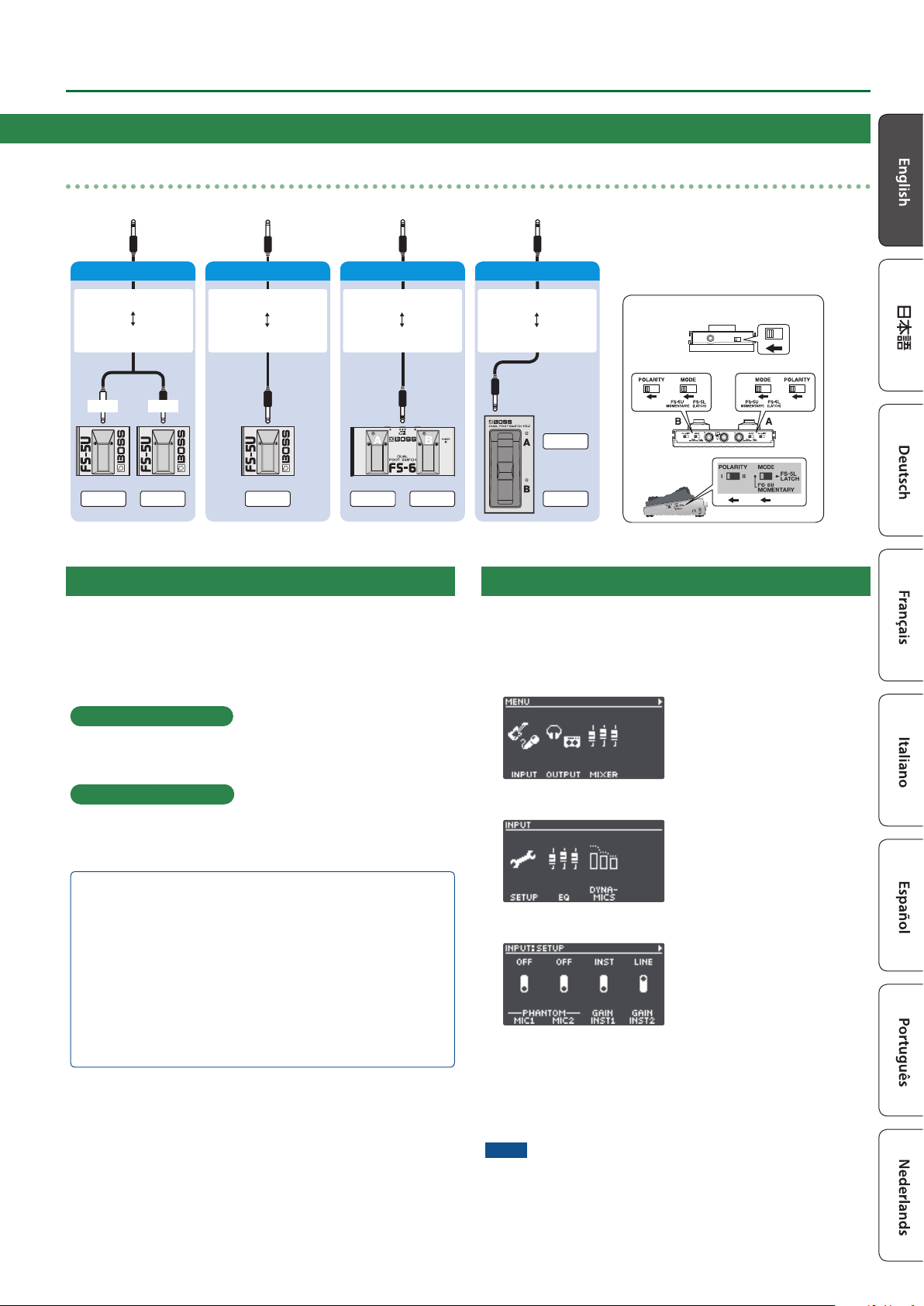
Phantom Power Settings
If you’re using a condenser mic that requires phantom power, use
the settings below to turn on this unit’s phantom power.
1. Press the [MENU] button.
2. Press the [1] (INPUT) knob.
3. Press the [1] (SETUP) knob.
4. Turn the [1] (MIC1)/[2] (MIC2) knobs to set PHANTOM
to “ON”.
5. Press the [EXIT] button to return to the play screen
(p. 8).
NOTE
Always turn the phantom power o when connecting any device
other than condenser microphones that require phantom power.
Rear Panel (Connecting Your Equipment)
Connecting footswitches
Connect one or more footswitches and set their mode/polarity switches by referring to the illustrations below.
FS-6
FS-7
CTL 2
FS-5U x 1
FS-5U
FS-6
Mode/Polarity switch
FS-7
1/4” phone type
1/4” phone type
Stereo 1/4” phone type
Stereo 1/4” phone type
Stereo 1/4” phone type
Stereo 1/4” phone type
CTL 1CTL 2 CTL 1CTL 1
RINGTIP
Stereo 1/4” phone type
1/4” phone type x 2
CTL 1 CTL 2
FS-5U x 2

8
Getting Ready
(1) MEMORY NUMBER
(2) TRACK STATUS
Loop track status is shown with an icon
Icon Explanation
Recording, playing back, overdubbing
Stopped (phrase exists)
No phrase
Current track
(3) LOOP TRACKS
Displays the track status + progress during playback
(4) LOOP STATUS
Indicates the status of the tracks
(5) LOOP LEVEL
Volume of each track is shown by the level meters
(6) INPUT FX
Indicates the input FX status
A B C D
O
On
(7) TRACK FX
Indicates the track FX status
* You can change which play screen is
shown on startup.
& “Parameter Guide” (PDF)
Switching Between Play Screens
The screen that appears after you turn on the power is called the “play screen”.
Icon Explanation
Tempo
Phantom power for MIC 1, 2 connectors is on (o when not displayed)
Knob lock function is on (o when not displayed)
Memory name
[1] [2] [3] [4]
Parameters to set using the [1]–[4] knobs
Memory number
Press the PAGE [K] or [J] button while the play screen is shown to switch between variations of the play screen.
Adjusting the Input/Output Level
Press the [ENTER] button while the play screen is shown to display the MIXER screen, where you can check the input/output levels for each
jack and connector.
Use the PAGE [K] [J] buttons to switch between pages, and turn the [1]–[4] knobs to adjust the respective input/output levels.
[J]
[K]
[J]
[K]
Mute: On ScalePeak indicator
Switches the page
5 Adjust the levels so that the peak indicator on the level meter matches the scale shown in the illustration.
5 For the inputs, push the [1]–[4] knobs to mute the sound.
5 Use the MASTER OUT to adjust the levels of the MAIN OUTPUT, SUB OUTPUT 1 and SUB OUTPUT 2. The [OUTPUT LEVEL] knob is
congured to adjust the levels as well by factory default.
The jacks and connectors shown in the MIXER screen may change, depending on the stereo link settings.
Stereo link Explanation
ON The MIC 1, 2 and L/R channels are shown as a single connector.
OFF The MIC 1, 2 and L/R channels are shown separately.
* For details on stereo link, refer to the “Parameter Guide” (PDF).
9
Getting Ready
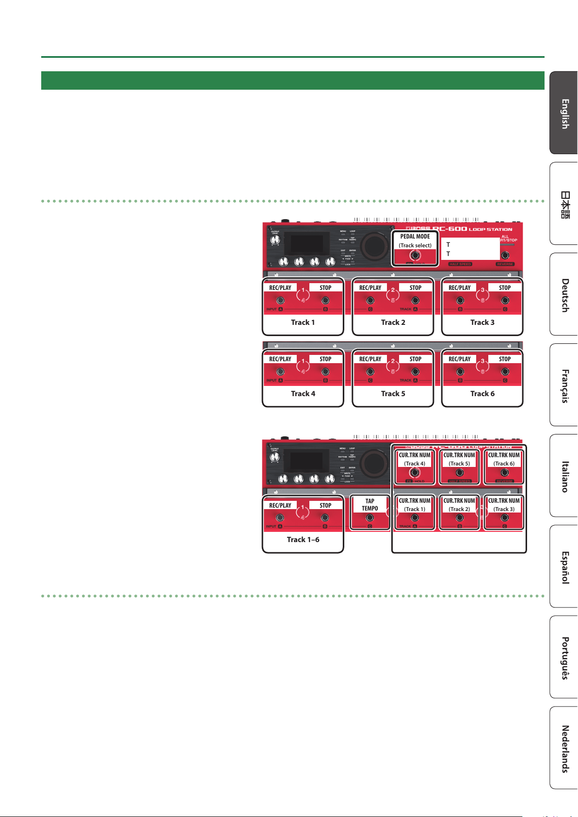
Pedal Mode
In Pedal mode, you can assign the functions you like to the nine switches on this unit as a set. This lets you eciently operate switches
such as record, playback and overdubbing.
5 Pedal mode features three separate modes, and you can switch between these three modes as sets.
5 You can also assign the function for selecting modes 1–3 to a switch you like.
5 The settings for modes 1–3 can be saved in memory, letting you use dierent settings for each pedal mode in memory.
Examples of settings
(1)
These are the basic (factory default) settings of the
RC-600.
Tracks 1–3
Tracks 4–6
REC/PLAY STOP
Track 1
REC/PLAY STOP
Track 2
REC/PLAY STOP
Track 3
REC/PLAY STOP
Track 4
REC/PLAY STOP
Track 5
REC/PLAY STOP
Track 6
PEDAL MODE
(Track select)
(2)
These are the settings for quickly selecting a desired
track.
CUR.TRK NUM
(Track 1)
CUR.TRK NUM
(Track 2)
CUR.TRK NUM
(Track 3)
CUR.TRK NUM
(Track 4)
CUR.TRK NUM
(Track 5)
CUR.TRK NUM
(Track 6)
TAP
TEMPO
Track select
REC/PLAY STOP
Track 1–6
Pedal mode settings
Make the Pedal mode settings by selecting the “PEDAL MODE1”–”PEDAL MODE3” parameters from “CTL FUNC” on the MENU screen
(p. 18).
For details on the parameters, refer to “Parameter Guide” (PDF).

10
Creating a Loop Phrase
Recording on a Single Track
Here’s how to record and overdub on track 1.
Getting ready to record
1. Connect your guitar or mic.
2. Adjusts the input/output level (p. 8).
3. Use the [OUTPUT LEVEL] knob to adjust the overall
volume of the RC-600.
4. On the play screen, turn the [1] (MEMORY) knob to
select a memory.
5. Press the [TRACK SELECT] switch to the tracks 1–3.
Indicator Explanation
Lit white Tracks 1–3
Lit red Tracks 4–6
Recording
1. Press the [REC/PLAY] 1 switch to start
recording.
The REC/PLAY indicator is lit red.
2. Play your guitar or vocalize into your mic to
input audio.
%
Playback
1. Press the [REC/PLAY] 1 switch.
The REC/PLAY indicator is lit green.
The recorded phrase plays as a loop.
%
Overdubbing
1. Press the [REC/PLAY] 1 switch to start
overdubbing.
The REC/PLAY indicator is lit yellow.
2. Overdub-record your performance (audio)
onto the phrase that’s playing as a loop.
%
Playback
%$
Repeat as many times
as necessary.
Overdubbing
:
Stopping
1. Press the [STOP] 1 switch.
The REC/PLAY indicator is lit white.
If you want to keep the recorded phrase, save it in
a memory (p. 13).
Undo/Redo
Press the [UNDO/REDO] switch during playback or overdubbing
to Undo.
Press the switch once again to Redo.
Indicator Explanation
Lit green Undo available
Lit red Redo available
Unlit Undo/redo not available
11
Creating a Loop Phrase
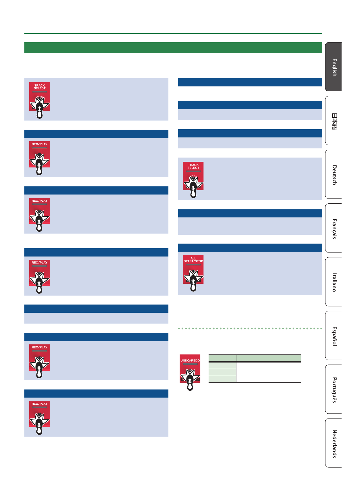
Recording on Multiple Tracks
You can use multiple tracks to create a single loop phrase.
This shows you how to record the tracks in ascending order (track 1 0 track 2 0 ... track 6).
Press the [TRACK SELECT] switch to the tracks
1–3.
The TRACK SELECT indicator is lit white.
%
Track 1 Recording
1. Press the [REC/PLAY] 1 switch to start
recording.
The REC/PLAY indicator is lit red.
2. Play your guitar or vocalize into your mic to
input audio.
%
Track 1 Playback
1. Press the [REC/PLAY] 1 switch.
The REC/PLAY indicator is lit green.
The recorded phrase plays as a loop.
%$
Repeat as many times as
necessary.
Track 1 Overdubbing
1. Press the [REC/PLAY] 1 switch to start
overdubbing.
The REC/PLAY indicator is lit yellow.
2. Overdub-record your performance (audio)
onto the phrase that’s playing as a loop.
:
Track 1 Playback
Press the [REC/PLAY] 1 switch.
%
Track 2 Recording
1. Press the [REC/PLAY] 2 switch to start
recording.
The REC/PLAY indicator is lit red.
2. Play your guitar or vocalize into your mic to
input audio.
%
Track 2 Playback
1. Press the [REC/PLAY] 2 switch.
The REC/PLAY indicator is lit green.
The recorded phrase plays as a loop.
%
Track 2 Overdubbing
%$
Repeat as many times as
necessary.
Track 2 Playback
Press the [REC/PLAY] 2 switch.
%
Track 3
As with track 2, record/playback/overdub tracks.
%
Press the [TRACK SELECT] switch to the tracks
4–6.
The TRACK SELECT indicator is lit red.
%
Track 4–6
As with track 2, record/playback/overdub tracks 40 5 0 6 in
ascending order.
:
Stopping
1. Press the [ALL START/STOP] button.
The ALL START/STOP indicator is go dark.
If you want to keep the recorded phrase, save it
in a memory (p. 13).
Undo/Redo
Press the [UNDO/REDO] switch during playback or overdubbing
to Undo.
Press the switch once again to Redo.
Indicator Explanation
Lit green Undo available
Lit red Redo available
Unlit Undo/redo not available
12
Creating a Loop Phrase
Record While Listening to the Rhythm Sound
In addition to the track, the RC-600 can also play a “Rhythm”.
You can record while sounding a rhythm at the tempo you specify.
Sounding a Rhythm
1. Press the [RHYTHM] button.
The rhythm switches on (lit)/o (unlit)/ready to play rhythm
(blink) each time you press the button.
Setting the Tempo of Rhythm
1. Press the [TAP TEMPO] button.
The tempo setting screen appears.
2. While the tempo setting screen is shown, turn the [4]
knob to set the tempo.
Value 40.0–300.0
MEMO
Press and then turn the [4] knob to set a value in decimal
points.
Tap tempo
You can set the tempo by pressing a button at the desired interval.
1. Press the [TAP TEMPO] button several times in time
with the desired tempo.
MEMO
If you long-press the [TAP TEMPO] button until it begins
blinking red, the tempo returns to the default value.
5 The specied tempo can be saved as a setting in memory.
& “Saving a Memory (WRITE)” (p. 13)
5 You can specify the volume and type (variation) of rhythm,
and how the rhythm plays.
& “Editing the Rhythm Settings” (p. 16)
Using the Input FX
You can apply input FX to the input sound.
1. Press the [LOOP] button.
The LOOP screen appears.
2. Use the PAGE [J] button to switch the page, and then
press the [1] (INPUT FX) knob.
3. Turn the [1]–[4] knobs to switch the eects (FX A–D)
on/o.
Switching between banks
4. Use the PAGE [J] button to switch the page, and then
turn the [1] (BANK) knob to select the bank.
Using the Track FX
5. To apply track FX to a track that’s already recorded, use
the same operation as with the input FX after pressing
the [2] (TRACK FX) knob mentioned in step 2.
5 You can save the eects you congured as settings in
memory.
& “Saving a Memory (WRITE)” (p. 13)
5 You can switch between eect types that are assigned to the
[A]–[D] buttons, and change how the eects sound.
& “Editing the Input FX/Track FX Settings” (p. 17)

13
Saving a Memory
Saving a Memory (WRITE)
If you select a dierent memory or turn o the power after
recording or editing the settings, the recorded content or edited
settings are lost. If you want to keep the data, you must save it.
1. Press the [EXIT] button and [ENTER] button
simultaneously.
The WRITE screen appears.
2. Press the [1] or [2] (WRITE) knob.
3. Turn the [1]–[4] knobs to select the memory to which
you want to save.
5 This procedure is not required if the memory number is
acceptable as is.
5 If you decide to cancel, press the [EXIT] button.
4. Press the [ENTER] button.
The memory is saved.
* Make sure not turn to o the power while the “EXECUTING...”
message is shown.
MEMO
You can assign a name to the memory. For details, refer to
“Parameter Guide” (PDF).
Erasing Data from a Memory (CLEAR)
You can erase the data that is saved in a memory, clearing that
memory to an empty state.
1. Press the [EXIT] button and [ENTER] button
simultaneously.
The WRITE screen appears.
2. Press the [3] or [4] (CLEAR) knob.
3. Turn the [1]–[4] knobs to select the memory you want
to clear.
5 This procedure is not required if the memory number is
acceptable as is.
5 If you decide to cancel, press the [EXIT] button.
4. Press the [ENTER] button.
The memory will be cleared.
* Make sure not turn to o the power while the “EXECUTING...”
message is shown.

14
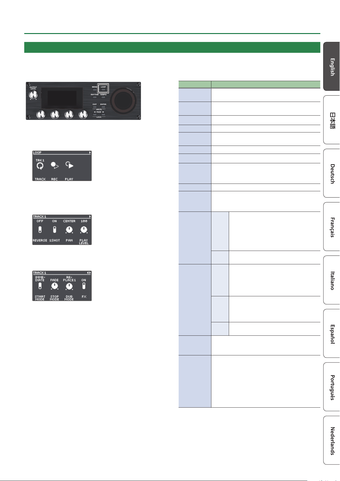
Editing a Memory
1. Press the [LOOP] button.
The LOOP screen appears.
2. Use the PAGE [K] [J] buttons to switch to the page
containing the item you want to edit.
3. Press the [1]–[4] knobs to select the parameter to edit.
4. Use the PAGE [K] [J] buttons to switch to the page
containing the parameter you want to edit.
5. Turn the [1]–[4] knobs to edit the values.
6. Press the [EXIT] button a number of times to return to
the play screen.
7. If you want to save the edited settings, execute the
Write operation (p. 13).
Item Explanation
TRACK
Congures tracks 1–6.
Turn the [1] knob to select the track to edit.
REC
Congures the settings related to recording/
overdubbing.
PLAY
Species how loop phrases play back.
INPUT FX
Congures the input FX.
TRACK FX
Congures the track FX.
RHYTHM
Congures the rhythm settings.
NAME
Species the memory name.
* Maximum of 12 characters
Editing the Settings of a Memory
Here’s how to edit the settings of each memory.
For details on the parameters, refer to “Parameter Guide” (PDF).
15
Editing a Memory
Editing the Track Settings
Here’s how to congure the volume, playback method and other settings for tracks 1–6.
For details on the parameters, refer to “Parameter Guide” (PDF).
1. Press the [LOOP] button.
The LOOP screen appears.
2. Turn the [1] (TRACK) knob to select the track to edit,
and then press the [1] (TRACK) knob.
The TRACK screen appears.
3. Use the [K] [J] buttons to switch to the page
containing the parameter you want to edit.
4. Turn the [1]–[4] knobs to edit the values.
5. Press the [EXIT] button a number of times to return to
the play screen.
6. If you want to save the edited settings, execute the
Write operation (p. 13).
Item Explanation
REVERSE
Species whether to play back normally or in
reverse.
1SHOT
Species whether to play back as one-shot or as
the usual loop playback.
PAN Species the stereo position (pan) of the track.
PLAY LEVEL Adjusts the playback level of the track.
START MODE
Species whether playback starts with a fade-in
or immediately when the track plays.
STOP MODE Species how the track stops.
DUB MODE Species the overdubbing method.
FX
Turns the eects (input FX/track FX) on/o.
* You can also press the [FX] button of the currently
selected track to switch the eect on/o.
PLAY MODE Specify how loop phrases play back.
MEASURE
Species the number of measures in the track.
* This parameter is available only if LOOP SYNC
SW is “ON”.
LOOP SYNC
SW
Sets whether to use loop sync (ON) or
not (OFF).
When loop sync is used, the memory’s
tempo or the tempo synchronized to
another track whose LOOP SYNC SW is
“ON” is used for recording and playback.
MODE
Sets how the loop sync operates (how
syncing is performed).
TEMPO SYNC
SW
Sets whether each track plays at its
original tempo (the tempo during
recording—use the OFF setting) or at the
tempo that is specied in the memory
(use the ON setting).
MODE
When TEMPO SYNC SW is “ON”, this sets
whether to change the pitch according
to the tempo, or to instead make the
pitch stay the same.
SPEED Sets the playback speed for each track.
BOUNCE IN
Sets whether to allow the playback sound from
a dierent track as well to be recorded during
recording or overdubbing.
INPUT
Sets whether the sound from each input jack/
connector and the rhythm should be inputted to
the track (ON) or not (OFF).
Turn the [1] knob to select the input jack/
connector or RHYTHM, and press the [1] knob to
switch between ON/OFF.
* When stereo link is “ON”, the MIC 1, 2 and L/R
channels are shown as a single connector.

16
Editing a Memory
1. Press the [LOOP] button.
The LOOP screen appears.
2. Use the PAGE [J] button to switch the page, and then
press the [3] (RHYTHM) knob.
The RHYTHM screen appears.
3. Use the [K] [J] buttons to switch between the
parameters that you want to edit.
4. Turn the [1]–[4] knobs to edit the values.
5. Press the [EXIT] button a number of times to return to
the play screen.
6. If you want to save the edited settings, execute the
Write operation (p. 13).
Item Explanation
GENRE Selects the genre of the rhythm pattern.
PATTERN Selects the rhythm pattern.
VARIATION Selects the rhythm pattern variation.
KIT Selects the drum kit used to play the rhythm.
BEAT Species the time signature of the rhythm.
START TRIG Species how rhythm playback starts.
STOP TRIG Species how rhythm playback stops.
INTRO REC
Sets whether to add an intro or not when
recording.
INTRO PLAY
Species whether the rhythm plays with or
without an intro.
ENDING
Species whether the rhythm plays with or
without an ending.
FILL
Species whether the rhythm plays with a ll-in
or without a ll-in.
VARI.
CHANGE
Species the timing at which the rhythm pattern’s
variation is changed.
Changing How the Rhythm Starts and Stops
As appropriate for your recording method or the phrase that
you’re recording, you can change the way in which the rhythm
starts and stops.
1. From the RHYTHM screen, switch to the page on which
“START TRIG” is shown.
2. Turn the [2] (START TRIG) knob to set the rhythm
playback method.
3. Turn the [3] (STOP TRIG) knob to set the rhythm stop
method.
4. Press the [EXIT] button a number of times to return to
the play screen.
5. If you want to save the edited settings, execute the
Write operation (p. 13).
Parameter Explanation
START TRIG
LOOP START
The rhythm plays when loop recording or
playback starts.
REC END
The rhythm plays when loop recording ends
and switches to playback.
This is useful if you want to perform without
specifying a tempo, start recording and then
play the loop in time with the rhythm when
playback starts.
BEFORE LOOP
The rhythm plays before loop recording or
playback.
The rhythm starts playing when you press the
switch once, and recording/playback starts
in time with the rhythm when you press the
switch once again.
STOP TRIG
OFF
The rhythm always continues playing.
If you are performing in synchronization with an
external MIDI device, you can keep the rhythm
playing continuously to allow synchronized
playback.
LOOP STOP The rhythm stops when the loop stops.
REC END
The rhythm stops when loop recording ends.
This is useful when you want to use the rhythm
as a guide during recording.
Editing the Rhythm Settings
For details on the parameters, refer to “Parameter Guide” (PDF).

17
Editing a Memory
Editing the Input FX/Track FX Settings
For details on the parameters, refer to “Parameter Guide” (PDF).
1. Select the memory for which you want to edit the
input FX/track FX settings.
2. Press the [LOOP] button.
The LOOP screen appears.
3. Use the PAGE [J] button to switch the page, and then
press the [1] (INPUT FX) or [2] (TRACK FX) knob.
The INPUT FX screen/TRACK FX screen appears.
4. Select the bank of the eect you wish to edit.
1. Use the PAGE [J] button to switch the page, and then turn
the [1] (BANK) knob to select the bank.
2. Press the PAGE [K] button to return to the previous page.
5. Press the [1]–[4] knobs to select the eect to edit.
6. Use the [K] [J] buttons to switch to the page
containing the parameter you want to edit.
* The available parameters depend on the type of eect you
select.
7. Turn the [1]–[4] knobs to edit the values.
8. Press the [EXIT] button a number of times to return to
the play screen.
9. If you want to save the edited settings, execute the
Write operation (p. 13).
18
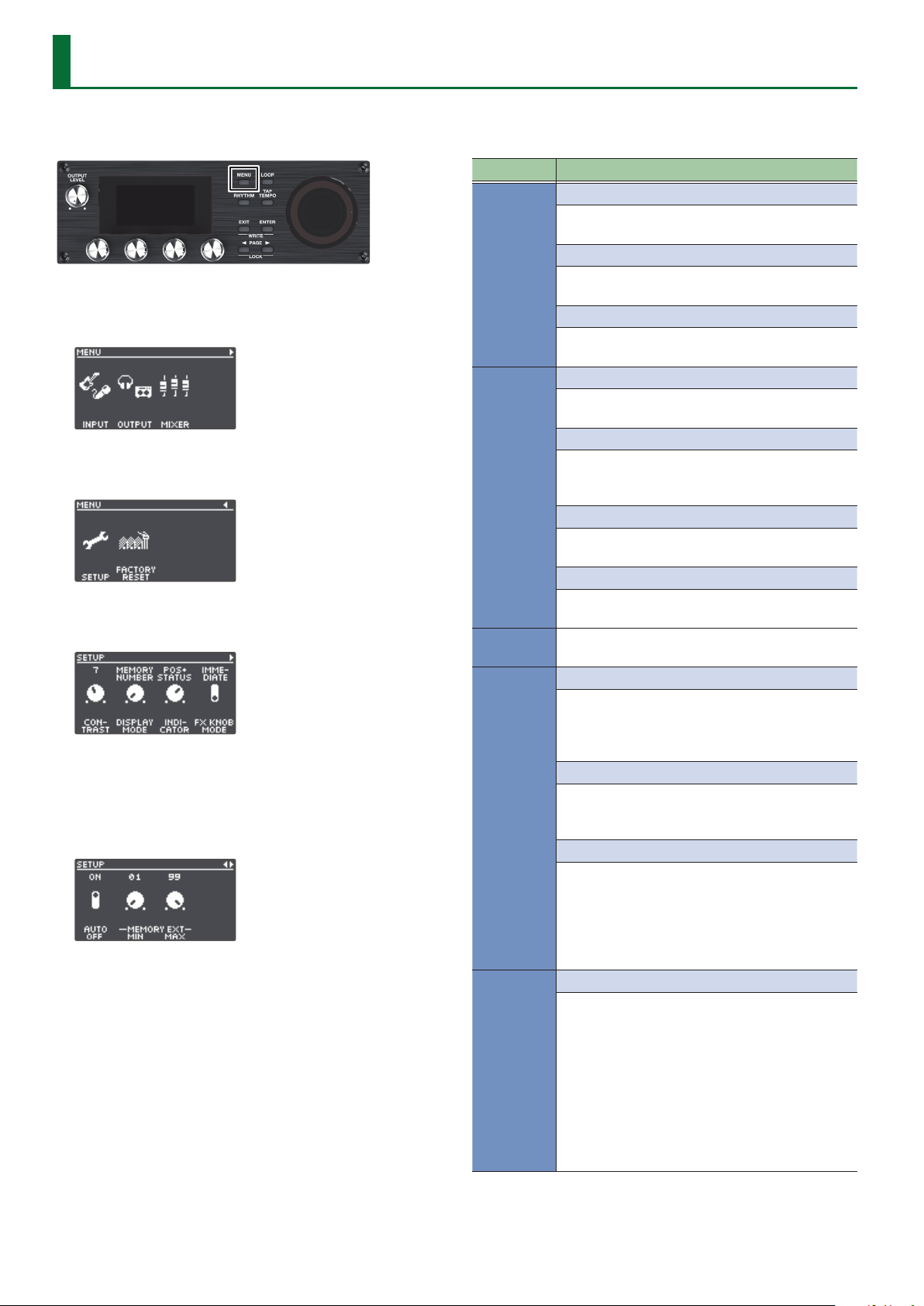
System Settings (MENU)
For details on the parameters, refer to “Parameter Guide” (PDF).
1. Press the [MENU] button.
The MENU screen appears.
2. Use the [K] [J] buttons to switch to the page
containing the item you want to edit.
3. Press the [1]–[4] knobs to select the item that you want
to edit.
4. If you see another screen with items to select, repeat
steps 2 and 3.
5. Use the [K] [J] buttons to switch to the page
containing the parameter you want to edit.
6. Turn the [1]–[4] knobs to change the value.
7. Press the [EXIT] button a number of times to return to
the play screen.
Item Parameter/Explanation
INPUT
SETUP
Settings related to the input and output jacks,
such as phantom power on/o.
EQ
Settings for applying an equalizer eect to the
input sound for each connector/jack.
DYNAMICS
Settings for applying a compressor or noise
suppressor to the input sound.
OUTPUT
SETUP
Settings related to the output jacks, such as stereo
link.
ROUTING
Settings for assigning the playback sound from
tracks 1–6 and the input/rhythm sound from each
input jack/connector to the output jacks.
EQ
Settings for applying an equalizer eect to the
output sound, congured for each output jack.
MASTER FX
Settings for the compressor and reverb eects
that are applied to the output sound.
MIXER
Sets the input/output levels for each jack and
connector (p. 8).
CTL FUNC
PANEL MODE 1–3
Settings for assigning functions to the [REC/PLAY]
switches x 3, the [STOP] switches x 3, the [TRACK
SELECT] switch, the [UNDO/REDO] switch and the
[ALL START/STOP] switch.
CTL/EXP
Settings for assigning functions to a footswitch or
expression pedal connected to the CTL 1, 2/EXP 1
jack or the CTL 3, 4/EXP 2 jack.
PREFERENCE
Selects whether to switch the PANEL MODE 1–3
and CTL/EXP settings to either the settings for
each memory or to the system settings.
* When switching to the settings for each
memory, use the write operation to save the
settings to memory.
ASSIGN
ASSIGN 1–16
Settings for the ASSIGN section.
By using the assign settings, you can control other
parameters at the same time as the specied
functions that are executed when you operate this
unit’s buttons/knobs, or a footswitch/expression
pedal connected to the CTL 1, 2/EXP 1 jack or CTL
3, 4/EXP 2 jack.
You can also congure this unit to be controlled
from an external MIDI device.
There are 16 dierent assign settings.

19
System Settings (MENU)
Item Parameter/Explanation
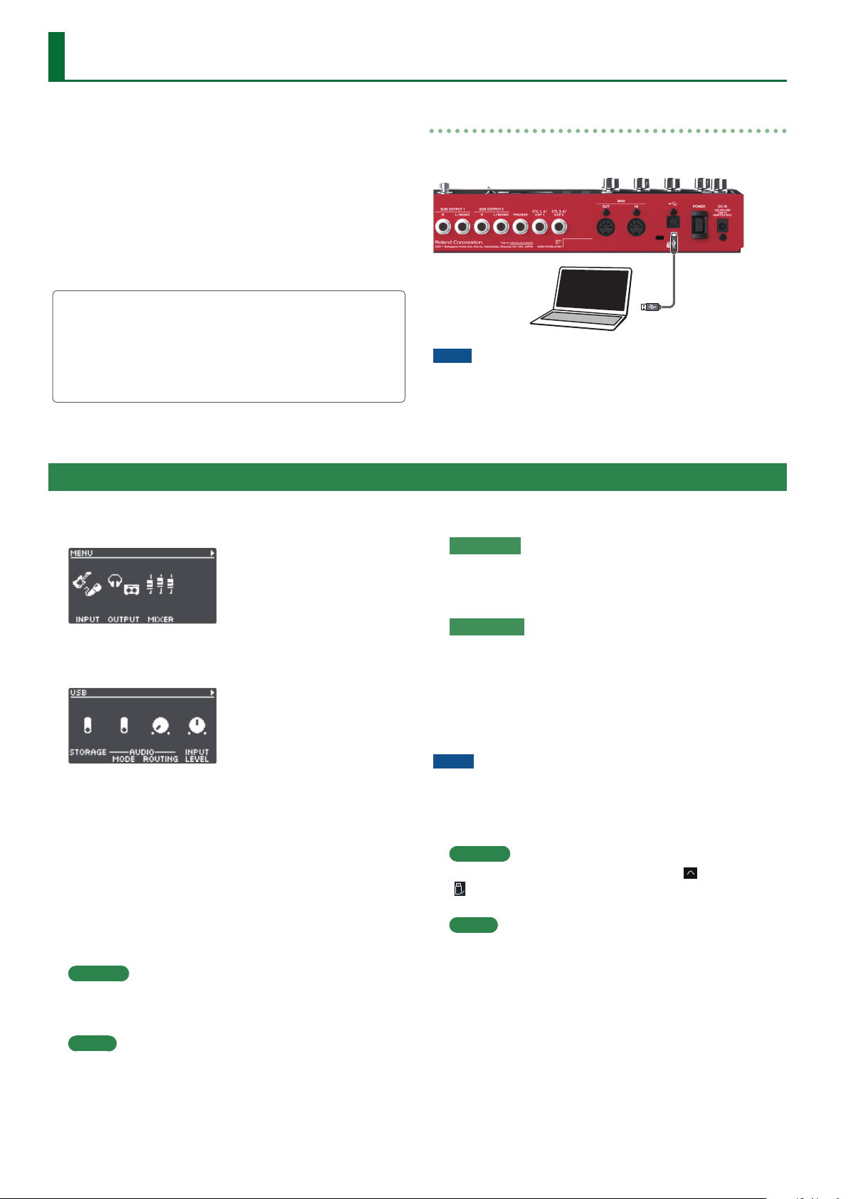
USB
STORAGE
Settings for how USB should operate.
AUDIO MODE
Settings for the USB driver when USB audio is
used.
AUDIO ROUTING
Settings for where the USB audio is routed.
INPUT LEVEL
Congures the USB audio input level.
OUTPUT LEVEL
Congures the USB audio output level.
MIDI
RX CH CTL
Species the receive channel for messages
(control changes) that switch memories or control
the RC-600.
RX CH RHYTHM
Species the receive channel for note messages
that play the drum sounds.
RX CH VOICE
Species the receive channel for note messages
used to create harmonies or vocoder eects.
TX CH
Species the transmit channel for MIDI messages.
SYNC CLOCK
Species the input to which the tempo clock is
synchronized.
SYNC OUT
Sets whether to output MIDI clock or not.
SYNC START
Species what starts in synchronization when a
MIDI start message is received.
PC OUT
Sets whether to transmit program change
messages or not.
THRU MIDI IN
Species the connector used to output the MIDI
messages received through the MIDI IN connector.
THRU USB IN
Species the connector used to output the MIDI
messages that are received through the USB port.
SETUP
CONTRAST
Adjusts the display contrast.
DISPLAY MODE
Sets which play screen is shown on startup.
INDICATOR
Settings for what the loop indicator should
display.
FX KNOB MODE
Sets how the [INPUT FX] knob/[TRACK FX] knob
operate.
AUTO OFF
Turns the AUTO OFF function on/o.
Item Parameter/Explanation
SETUP
MEMORY EXT MIN, MAX
Species the extent (lower limit and upper limit)
to which memories can be switched.
KNOB FUNC 1–4
Species the functions that are assigned to the
[1]–[4] knobs.
FACTORY
RESET
Restores the unit to its factory settings (p. 25).
20
Connecting to a Computer via USB
1. Press the [MENU] button.
The MENU screen appears.
2. Use the [K] [J] buttons to switch to the page on which
“USB” is shown, and press the [2] (USB) knob.
3. Turn the [1] (STORAGE) knob to set “PREPARING...”.
4. Use a USB cable to connect the RC-600’s USB port to
your computer’s USB port.
When a connection with the computer is established, the
message “CONNECTING...” appears.
* USB connection is not possible if the unit is not stopped, or if
there is a phrase that has not been saved.
5. Open the BOSS RC-600 drive.
Windows
Within My Computer (or Computer), open “BOSS RC-600” (or
Removable Disk).
macOS
On the desktop, open the “BOSS RC-600” icon.
6. Back-up or recover the data.
Backup
Copy the entire “ROLAND” folder from the BOSS RC-600 drive
to your computer.
Recover
* When you execute this operation, the memory currently saved
in the RC-600 disappears. Back up in advance.
In the BOSS RC-600 drive, delete the “ROLAND” folder,
and then copy the backed-up “ROLAND” folder from the
computer into the BOSS RC-600 drive.
NOTE
Do not delete the folders in the BOSS RC-600 drive other than
when executing the recovery operation.
7. Eject the BOSS RC-600 drive.
Windows
In the lower right of your screen, click the [
] and then the
[
] icon, and then click “Eject BOSS RC-600”.
macOS
Drag the “BOSS RC-600” icon to the trash (“Eject” icon).
Here’s what you can do when you connect the RC-600 via USB to
your computer.
5 Back up the RC-600’s data to your computer.
5 Restore (recover) backup data from your computer to the
RC-600.
5 Use BOSS TONE STUDIO to import or back up loop phrases
(audio les).
5 Use the dedicated rhythm converter if you want to import and
use your original rhythm patterns on the RC-600.
Using BOSS TONE STUDIO and the rhythm converter
Access the website shown below to download BOSS TONE
STUDIO or the rhythm converter.
& https://www.boss.info/support/
Connecting to your computer
Use a commercially available USB cable to connect the RC-600’s
USB port to the USB port on your computer.
NOTE
5 Use a USB cable that supports USB 2.0 Hi-Speed.
5 This might not work correctly for some models of computer.
Refer to the BOSS website for details on the operating systems
that are supported.
Backing Up or Recovering Data
21
Controlling Devices via MIDI
Connect external MIDI devices to this unit according to your
needs.
Connector Explanation
MIDI IN
Receives messages from another MIDI device.
MIDI OUT
Transmits messages from this device.
Connection
MIDI Settings
Use of MIDI requires that the MIDI channels be matched with those of the connected device. Data cannot be transmitted to, nor received
from another MIDI device unless the MIDI channels are set properly.
For details on each of the MIDI setting parameters, refer to “Parameter Guide” (PDF).
Controlling an External MIDI Device from the RC-600
Overview Explanation
Transmitting tempo data and data for starting and stopping playback
The RC-600’s performance tempo
data is transmitted to external
MIDI devices as MIDI Clock.
Setting an external MIDI device to the same tempo as the RC-600
MIDI Clock messages are output from the RC-600 at all times.
Set the external MIDI device beforehand so it is ready to receive MIDI Clock and MIDI Start and
Stop messages. For details, refer to the owner’s manual of your device.
Playback start and stop operations
with the RC-600’s switches can be
transmitted as MIDI Start and Stop
messages.
Transmitting Start/Stop
A MIDI Start message is transmitted at the moment that recording or playback of the track begins,
when tracks had been stopped. This message is also transmitted when an All Start is carried out.
A MIDI Stop message is transmitted when tracks have stopped. This is also transmitted when All
Stop is carried out.
* If you want MIDI synchronized performance to continue even after the track stops, set the
RHYTHM parameter STOP TRIG (p. 16) to “OFF”.
* Tracks whose 1SHOT setting (p. 15) is “ON” and tracks whose LOOP SYNC SW setting (p. 15) is
“OFF” will not transmit Start/Stop data.
Transmitting Program Change messages
When a memory is selected with
the RC-600, a Program Change
message corresponding to the
selected memory number is
transmitted simultaneously.
Transmitting Program Change messages
When memories are switched on the RC-600, a MIDI Program Change message is transmitted to
the connected external MIDI device. You can transmit Program Change messages numbered 1
through 99, corresponding to the 99 individual memories 01–99.
* Set “PC OUT” (p. 19) to ON beforehand.
* Program Change messages 100–128 cannot be transmitted.
* Bank Select MIDI messages (Control Change #0, #32) cannot be transmitted.
Transmitting Control Change messages
Operating information for the
RC-600’s switches, buttons, knobs,
and an external expression pedal
or footswitch is transmitted as
Control Change messages.
Transmitting Control Change messages
If you select a Control Change as the “ASSIGN” (p. 18) target, you can transmit MIDI control
change messages by operating the buttons and knobs on the RC-600, or by using an external
footswitch or expression pedal (connected to the CTL 1, 2/EXP 1 jack or the CTL 3, 4/EXP 2 jack).

22
Controlling Devices via MIDI
Controlling the RC-600 from an External MIDI Device
Overview Explanation
Receiving tempo data and data for starting and stopping playback
The RC-600 will synchronize to the
tempo of MIDI Clock data from an
external MIDI device.
Setting the RC-600 to the same tempo as an external MIDI device
Make settings on your external MIDI device so that it will transmit MIDI Clock and MIDI Start/Stop
data. For details, refer to the owner’s manual of your device.
Set the RC-600’s SYNC CLOCK (p. 19) to “AUTO”.
* You can’t switch the tempo during recording.
Start/stop data will be received
from an external MIDI device to
play/stop the RC-600.
Receiving MIDI Start
When MIDI Start (FA) is received, all tracks will play (All Start).
Switching memories
The RC-600’s memories switch
simultaneously upon receipt of
corresponding Program Change
messages from external MIDI
devices.
Switching memories
You can switch the RC-600’s memories with Program Change messages from external MIDI devices.
You can receive Program Change messages numbered 1 through 99, corresponding to the 99
individual memories 01–99.
* Program Change messages 100–128 cannot be received.
* Even if received, Bank Select MIDI messages (Control Change #0, #32) are disregarded.
Receiving Control Change messages
The RC-600 can be controlled
using Control Change messages
from external MIDI devices.
Receiving Control Change messages
You can use Control Change messages from an external MIDI device to control functions that
would be dicult to control using the RC-600’s own controllers.
In the “ASSIGN” (p. 18) setting, set SOURCE to “MIDI CC#1–#31, CC#64–#95”, and select the
parameter that you want to control in TARGET.
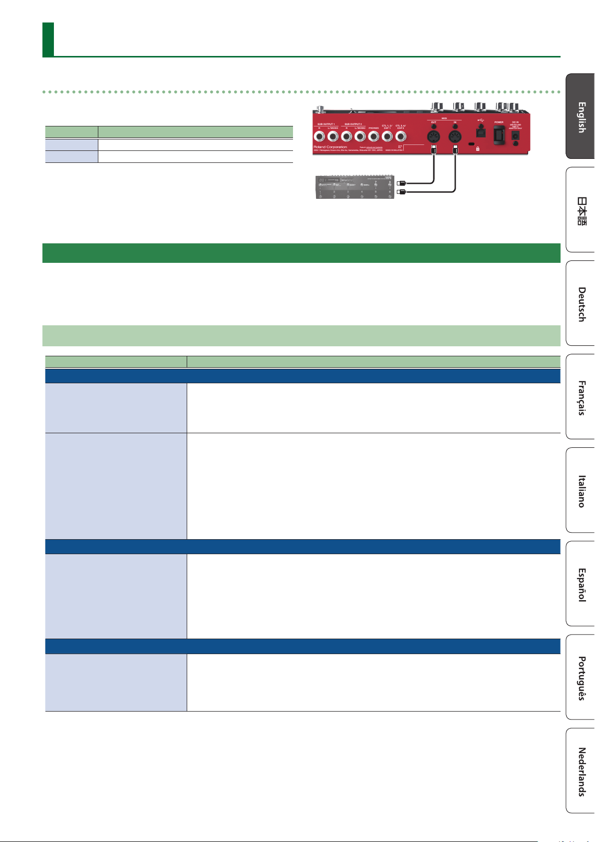
Connecting Two RC-600 Units
Two RC-600 units can be synchronized after connecting them together using a MIDI cable.
MIDI OUT MIDI IN
Transmitting unit Receiving unit
5 Begin recording on the tracks of the transmitting RC-600.
5 When you press the [ALL START/STOP] button on the transmitting RC-600, the receiving RC-600 also plays back.
* The receiving RC-600 performs an “all start” when tracks start playing back on the transmitting RC-600.
5 Tracks for which TEMPO SYNC SW (p. 15) is “ON” play at the tempo set in the memory of the transmitting unit.
5 Tracks for which LOOP SYNC SW (p. 15) is “ON” loop in time with the rst-recorded phrase on the transmitting RC-600.

23
Appendix
Troubleshooting
Problem Items to Check Action
Problems with sound
No sound/insucient
volume
Is this unit properly connected to other devices? Check the connections to other devices (p. 7).
Is the power to the connected amp or mixer not
turned on, or is the volume turned down?
Check the settings for connected devices.
Is there a short in one of the connection cables? Try replacing the connection cable.
The [OUTPUT LEVEL] knob have been lowered? Adjust knob to suitable position.
Is the input/output level set correctly?
Adjust the input/output levels on the MIXER screen for the input/output
jacks and connectors respectively.
Are the levels for tracks 1–6 set correctly?
Check the “PLAY LEVEL” setting for each track (p. 15).
Check whether an external expression pedal or other accessory has
been set to adjust the levels (p. 18).
Are the audio output destinations for tracks 1–6
set correctly?
Check the “ROUTING” settings in OUTPUT on the MENU screen (p. 18).
Has anything been recorded to the tracks?
Check the REC/PLAY indicator for each track to see whether the
track has been recorded. If a track’s button is unlit, nothing has been
recorded on that track.
No rhythm sound
Is the rhythm volume set correctly? Check the “RHYTHM OUT” setting on the MIXER screen.
Is the output destination for the rhythm sound
set correctly?
Check the RHYTHM settings in “ROUTING”, found in OUTPUT on the
MENU screen (p. 18).
Sound is missing from
the beginning and end
of a recorded track
To prevent noise, a fade-in and a fade-out are applied at the beginning and end of a recording. In some cases, it may sound
as if some of the sound has been cut out.
Unable to hear sounds
from devices connected
to the MIC IN 1, 2
connectors/INST IN 1, 2
jacks
Is the audio output destination set correctly?
Check the MIC 1/MIC 2/INST 1/INST 2 settings in “ROUTING”, found in
OUTPUT on the MENU screen (p. 18).
Problems with operation
Cannot switch between
memories
Is something other than the play screen
appearing in the display?
You cannot switch memories while any screen other than the play
screen is displayed. Press the [EXIT] button to return to the play screen.
Recording/overdubbing
stops before nishing
Is there enough memory remaining?
If there isn’t enough memory, clear any unneeded memories (p. 13)
before recording or overdubbing.
Is LOOP SYNC SW (p. 15) set to “ON” for the
track?
When recording with LOOP SYNC SW set to “ON”, once the end of
the longest track is reached, this unit automatically switches to
overdubbing.
Playback tempo not
changing
Is recording or overdubbing in progress?
You cannot change the tempo of the memory while recording or
overdubbing. Change the tempo while the tracks are stopped or
playing back.
Is TEMPO SYNC SW (p. 15) set to “ON” for the
track?
When TEMPO SYNC SW is not set to “ON” for a track, the playback speed
does not change even if the tempo for the memory changes. To match
the playback speed to the tempo of the memory, set the track’s TEMPO
SYNC SW setting to “ON”.
Playback tempo not
changing
Is the unit synchronized via MIDI?
If MIDI clocks are being received via the MIDI IN connector or the USB
port, the RC-600 synchronizes its tempo to the MIDI clocks.
If you don’t want to synchronize with an external device, set SYNC to
“INTERNAL”.
MIDI messages not
being transmitted/
received
Is the external MIDI device properly connected? Check the connections to the external MIDI device.
Could there be a short in the MIDI cable? Try replacing the MIDI cable.
Are the MIDI channels matched to those of the
external MIDI device?
Conrm that both devices are set to the same MIDI channels.
If transmitting from the RC-600, have you made
the necessary transmission settings?
Check the TX CH (transmit channel) setting and the PC OUT (program
change message transmit) on/o setting.
Problems with USB
Unable to communicate
with computer
Is the USB cable properly connected? Check the connection (p. 20).
(If exchanging les via USB with your computer)
Could “STORAGE” be OFF?
Using the procedure shown in “Backing Up or Recovering Data” (p. 20),
set STORAGE to “PREPARING...”.
Is a memory now being edited?
USB connection is not possible if there is an unsaved memory.
Save the memory (p. 13), and then try the USB connection again.

24
Appendix
Error Message List
Message Meaning Action
LOOPER
DATA DAMAGED
Data may have been damaged.
In the factory reset function (p. 25), choose “SYS+MEM” to
return the RC-600 to its factory settings.
DATA READ ERR
A problem has occurred with the content of the
RC-600’s memory.
Consult your dealer, a Roland service center, or an ocial Roland
dealer.
DATA WRITE ERR
DATA TOO LONG
Playback is not possible because the recording time or
audio le is too long.
The recording time or audio le length must not exceed 1.5
hours.
DATA TOO SHORT
Playback is not possible because the recording time or
audio le is too short.
The recording time or audio le length must be at least 0.1
seconds.
EVENT FULL
Further overdubbing is not possible. Save the memory (p. 13).
MEMORY FULL
The recorded time of one track exceeded 1.5 hours
(approximately).
No further recording is possible on the current track.
Save the memory (p. 13). If you want to continue recording,
select a dierent memory.
The total recording time of all memories exceeded 13
hours (approximately).
No further recording is possible.
Clear unneeded memories (p. 13).
NOT EMPTY
You are attempting to overwrite-save onto a memory in
which a phrase is already recorded.
Either clear the currently selected memory (p. 13), or select an
empty memory.
TEMPO TOO FAST
Since the track is being played at a much faster tempo
than when it was recorded, it might not play back
correctly.
Adjust the tempo.
TEMPO TOO SLOW
Since the track is being played at a much slower tempo
than when it was recorded, it might not play back
correctly.
TOO BUSY
TOO BUSY OMSG
The RC-600 could not process the data completely.
For “TOO BUSY OMSG”:
Since you attempted to apply the loop FX to a phrase
that was set to a signicantly slower tempo than when
it was recorded, the data could not be processed quickly
enough.
Lower the performance tempo.
In the case of “TOO BUSY OMSG”, return to the tempo that was
used during recording.
Save the current content to a memory.
If this appears frequently, back up the data to your computer,
then execute factory reset “SYS+MEM”, and then recover the data
(p. 25, p. 20).
UNDEFINED ERR
An error of unknown cause has occurred during
recording, playback, or overdubbing.
Consult your dealer, a Roland service center, or an ocial Roland
dealer.
MIDI
BUFFER FULL
An excessive volume of messages were received and
could not be processed properly.
Reduce the number or size of MIDI messages transmitted to the
RC-600.
OFFLINE
There is a problem with the MIDI cable connection.
Check to make sure the cable has not been disconnected and
that there is no short in the cable.
Others
MEMORY FULL
This unit’s memory is insucient. If this message
appears, recording or overdubbing might end mid-way.
Clear unneeded memories (p. 13), and then try recording
again.
STOP LOOPER
The operation is not possible during recording,
playback, or overdubbing.
Stop before performing the operation.
STOP ALL
The operation is not possible during recording,
playback, overdubbing, or rhythm playback.
Stop all of these before performing the operation.
STOP ALL&SAVE
The operation is not possible during recording,
playback, overdubbing, or rhythm playback when there
is also unsaved data.
Stop all of these, and then save the memory (p. 13).
UNSUPPORTED FILE
This audio le is unplayable.
Check the format of the audio le.
To import an audio le into the RC-600, use BOSS TONE STUDIO.

25
Appendix
Restoring the Factory Default Settings
(Factory Reset)
You can restore all of the settings to their factory-set values, and
you can also specify certain items to be reset.
* When you execute “Factory Reset”, the settings you made are
lost. Back up any necessary data to your computer.
1. Press the [MENU] button.
The MENU screen appears.
2. Use the [K] [J] buttons to switch to the page on
which “FACTORY RESET” is shown, and press the [4]
(FACTORY RESET) knob.
3. Turn the [1]–[4] knobs to select the setting that you
want to restore.
Value Explanation
MEMORY Memory 01–99
SYSTEM System settings
MEMORY+SYSTEM Memory 01–99 and system settings
* If you decide to cancel, press the [EXIT] button.
4. Press the [ENTER] button.
The factory reset is executed.
* Make sure not turn to o the power while the “EXECUTING...”
message is shown.
Once the factory reset is complete, you are returned to the Play
screen.

26
Appendix
Main Specications
Sampling Frequency 44.1 kHz
AD/DA Conversion 32 bits
Processing 32-bit oating point
Recording/Playback
Number of Tracks: 6
Data Format: WAV (44.1 kHz, 32-bit oat, stereo)
Maximum Recording Time: Approx. 1.5 hours (1 track), Approx.13 hours (total of All memories)
Rhythm Type 200 types or greater
Rhythm Kit 16 types
Eect
INPUT FX: 49 types
TRACK FX: 53 types
MASTER FX: 2 types
Memory 99
Nominal Input Level
MIC IN 1, 2: -40 dBu
INST IN 1, 2: -10 dBu
Maximum Input Level
MIC IN 1, 2: 0 dBu
INST IN 1, 2: +7 dBu/+20 dBu (selectable)
Input Impedance
MIC IN 1, 2: 3 kΩ
INST IN 1, 2: 1 MΩ/25 kΩ (selectable)
Nominal Output Level
MAIN OUTPUT: -10 dBu
SUB OUTPUT 1, 2: -10 dBu
Maximum Output Level
MAIN OUTPUT: +7 dBu
SUB OUTPUT 1, 2: +7 dBu
Output Impedance
MAIN OUTPUT: 1 kΩ
SUB OUTPUT 1, 2: 1 kΩ
Recommended Load Impedance
MAIN OUTPUT: 10 kΩ or greater
SUB OUTPUT 1, 2: 10 kΩ or greater
Display Graphic LCD (128 x 64 dots, backlit LCD)
Connectors
MIC IN 1, 2 connectors: XLR type (balanced, phantom power: DC 48 V, 10 mA Max)
INST IN 1, 2 jacks, MAIN OUTPUT jacks, SUB OUTPUT 1, 2 jacks: 1/4-inch phone type
PHONES jack: Stereo 1/4-inch phone type
CTL1,2/EXP1 jack, CTL3,4/EXP2 jack: 1/4-inch TRS phone type
USB port: USB B type
MIDI (IN, OUT) connectors
DC IN jack
Power Supply AC adaptor
Current Draw
1.2 A (with phantom power)
1.1 A (without phantom power)
Dimensions
435 (W) x163 (D) x 66 (H) mm
17-1/8 (W) x 6-7/16 (D) x 2-5/8 (H) inches
Weight
2.4 kg
5 lbs 5 oz
Accessories
AC adaptor
Owner’s Manual
Leaet “USING THE UNIT SAFELY”
Options (sold separately)
Footswitch: FS-5U
Dual Footswitch: FS-6, FS-7
Expression Pedal: FV-500H, FV-500L, EV-30, Roland EV-5
* 0 dBu = 0.775 Vrms
* This document explains the specications of the product at the time that the document was issued. For the latest information, refer to
the Roland website.