
USER MANUAL
MANUALE D’USO
ES 3323-II
- 3-ZONE MIXER-AMPLIFIER
WITH TUNER AND
CD/USB – MP3 PLAYER
- MIXER-AMPLIFICATORE CON
SELEZIONE DI 3 ZONE E
SINTONIZZATORE RADIO /
LETTORE CD/USB – MP3


ENGLISH
SAFETY PRECAUTIONS
DESCRIPTION
FRONT PANEL
REAR PANEL
OPERATION MODES
SINGLE MODE OPERATION
PRIORITY
DUAL AMPLIFICATION ‘A’
DUAL AMPLIFICATION ‘B’
ADDITIONAL EXTERNAL AMPLIFIER CONNECTION
FURTHER INFORMATION
RCF BM 3001 / BM 3003 PAGING MICROPHONES
CD/USB – MP3/WMA PLAYER AND TUNER
LOUDSPEAKER CONNECTION
ZONE OUTPUT 100 V / 70 V (COMMON) VOLTAGE SELECTION
POWER SUPPLY VOLTAGE CHANGE
SPECIFICATIONS
EXAMPLES OF CONNECTIONS
ITALIANO
AVVERTENZE PER LA SICUREZZA
DESCRIZIONE
PANNELLO FRONTALE
PANNELLO POSTERIORE
MODALITÀ DI FUNZIONAMENTO
FUNZIONAMENTO IN MODALITÀ SINGOLA
PRIORITÀ
FUNZIONAMENTO CON DOPPIA AMPLIFICAZIONE (“A”)
FUNZIONAMENTO CON DOPPIA AMPLIFICAZIONE (“B”)
COLLEGAMENTO DELL’AMPLIFICATORE ESTERNO ADDIZIONALE
ULTERIORI INFORMAZIONI
BASI MICROFONICHE RCF BM 3001 E BM 3003
USO DEL LETTORE CD/USB – MP3/WMA E SINTONIZZATORE RADIO
COLLEGAMENTO DEI DIFFUSORI ACUSTICI
CAMBIO TENSIONE 100 V / 70 V (COMUNE) ALLE USCITE DI ZONE “ZONE OUTPUTS”
CAMBIO TENSIONE DI FUNZIONAMENTO DELL’APPARECCHIO
SPECIFICHE TECNICHE
ESEMPIO COLLEGAMENTI
4
6
7
9
14
14
15
18
19
19
21
22
23
31
32
33
34
36
38
40
41
43
48
48
49
52
53
53
55
56
57
65
66
67
68
70
TABLE OF CONTENTS
INDICE

4
ENGLISH
IMPORTANT
WARNING
SAFETY PRECAUTIONS
Before connecting and using this product, please read this instruction manual carefully and
keep it on hand for future reference. The manual is to be considered an integral part of
this product and must accompany it when it changes ownership as a reference for correct
installation and use as well as for the safety precautions.
RCF S.p.A. will not assume any responsibility for the incorrect installation and / or use of
this product.
WARNING: To prevent the risk of re or electric shock, never expose this product to rain
or humidity.
SAFETY PRECAUTIONS
1. All the precautions, in particular the safety ones, must be read with special attention, as
they provide important information.
2. POWER SUPPLY FROM MAINS
- The mains voltage is sufciently high to involve a risk of electrocution: never install or
connect this product when its power cable is plugged in.
- Before powering up, make sure that all the connections have been made correctly and
the voltage of your mains corresponds to the voltage shown on the rating plate on the
unit, if not, please contact your RCF dealer.
- The metallic parts of the unit are earthed by means of the power cable.
An apparatus with CLASS I construction shall be connected to a mains socket outlet
with a protective earthing connection.
- Protect the power cable from damage; make sure it is positioned in a way that it cannot
be stepped on or crushed by objects.
- To prevent the risk of electric shock, never open the product: there are no parts inside
that the user needs to access.
3. Make sure that no objects or liquids can get into this product, as this may cause a short
circuit.
This apparatus shall not be exposed to dripping or splashing. No objects lled with liquid,
such as vases, shall be placed on this apparatus. No naked sources (such as lighted candles)
should be placed on this apparatus.
4. Never attempt to carry out any operations, modications or repairs that are not expressly
described in this manual.
Contact your authorized service centre or qualied personnel should any of the following
occur:
- The product does not function (or functions in an anomalous way).
- The power supply cable has been damaged.
- Objects or liquids have got into the unit.
- The product has been subject to a heavy impact.
5. If this product is not used for a long period, disconnect the power cable.
6. If this product begins emitting any strange odours or smoke, switch it off immediately
and disconnect the power supply cable.
7. The terminals marked with the symbol
are HAZARDOUS LIVE and their connection
is to be made by an INSTRUCTED PERSON or the use of ready-made cables is required.
8. Do not connect this product to any equipment or accessories not foreseen.
For suspended installation, only use the dedicated anchoring points and do not try to hang
this product by using elements that are unsuitable or not specic for this purpose.

5
ENGLISH
IMPORTANT NOTES
OPERATING PRECAUTIONS
Also check the suitability of the support surface to which the product is anchored (wall,
ceiling, structure, etc.), and the components used for attachment (screw anchors, screws,
brackets not supplied by RCF etc.), which must guarantee the security of the system /
installation over time, also considering, for example, the mechanical vibrations normally
generated by transducers.
To prevent the risk of falling equipment, do not stack multiple units of this product unless
this possibility is specied in the user manual.
9. RCF S.p.A. strongly recommends this product is only installed by professional qualied
installers (or specialised rms) who can ensure correct installation and certify it according
to the regulations in force.
The entire audio system must comply with the current standards and regulations regarding
electrical systems.
10. SUPPORTS AND TROLLEYS
The equipment should be only used on trolleys or supports, where necessary, that are
recommended by the manufacturer. The equipment / support / trolley assembly must be
moved with extreme caution. Sudden stops, excessive pushing force and uneven oors may
cause the assembly to overturn.
11. There are numerous mechanical and electrical factors to be considered when installing
a professional audio system (in addition to those which are strictly acoustic, such as sound
pressure, angles of coverage, frequency response, etc.).
12. HEARING LOSS
Exposure to high sound levels can cause permanent hearing loss. The acoustic pressure
level that leads to hearing loss is different from person to person and depends on the
duration of exposure. To prevent potentially dangerous exposure to high levels of acoustic
pressure, anyone who is exposed to these levels should use adequate protection devices.
When a transducer capable of producing high sound levels is being used, it is therefore
necessary to wear ear plugs or protective earphones.
See the technical specications in loudspeaker instruction manuals to know their maximum
sound pressure levels.
To prevent the occurrence of noise on microphone / line signal cables, use screened cables
only and avoid putting them close to:
- Equipment that produces high-intensity electromagnetic elds (for example, high power
transformers)
- Mains cables
- Loudspeaker lines.
- Do not obstruct the ventilation grilles of the unit. Situate this product far from any heat
sources and always ensure adequate air circulation around the ventilation grilles.
- Do not overload this product for a long time.
- Never force the control elements (keys, knobs, etc. ).
- Do not use solvents, alcohol, benzene or other volatile substances for cleaning the
external parts of this product.
CLASS 1
LASER PRODUCT

6
ENGLISH
DESCRIPTION
ES 3323-II is a mixer-amplifier with 4 mic-line inputs on removable connectors (the
first input also has an XLR socket), a CD/USB – MP3/WMA player and tuner, 2 aux
inputs (one on the rear panel with dual RCA connector, one on the front player with
1/8” jack) for additional external music sources.
The amplifier nominal power (320 W) is freely allocable to three 100 – 70 V separated
outputs (3-system zones, for loudspeakers having 100 – 70 V transformers). A common
direct output on 100 – 70 V constant voltage line and a low impedance (min. 4 Ω) 2 W
output for a monitor loudspeaker are available.
As (optional) system expansion, it is possible to link a second generic external
amplifier (delivering enough power for all loudspeakers, i.e. RCF UP 2321) to keep the
background music in the zones that are not paged.
When the external amplifier is foreseen, it is possible to send the music signal to either
the ES 3323 internal amplifier or the external one.
The 3 PAGING buttons on the front panel can be used to select zones to be paged by
either the channel 1 or 4; a GENERAL call button is available as well. When connecting
an additional external amplifier and with no priority event in progress, the 3 PAGING
buttons (if turned on) send the mix of channels 1 ÷ 4 to the respective zones.
The 3 MUSIC buttons turn the music on (or send the mix of all inputs, when no priority
event in progress and ES 3323 is operating as a single stand-alone amplifier) in the
respective zones.
The input1 has a signal detection circuit (‘VOX’) providing automatic priority operation.
All the inputs 1, 2, 3 and 4 can get the priority through an external command
(connected to the removable connector). The inputs 2 and 3 also have an RJ 45 socket
for quick connection (through CAT5 cable) of either a RCF BM 3001 or BM 3003
paging microphone or a line (daisy-chain) of BM 3003 (made of max. 12 microphones,
by using an additional power supply unit).
A USB port (on the front panel) allows connection of a USB flash drive containing MP3
/ WMA files.
It is also possible to match a ‘Bluetooth’ device (e.g. a mobile phone) to the player.
Aux outputs are available to send the internal / external music source signals to
additional amplifiers, mixers, phone systems (‘music on hold’ function), etc. .
The 4 mic.-line inputs have a common ‘presence’ control and separate high-pass filters
that are useful for improving speech intelligibility.
Both the internal music source (CD/USB – MP3/WMA player and tuner) and the rear
panel AUX INPUT have separate tone controls.
Front panel LED’s indicate the device state (ON, PROT), the priority activation (PRIOR)
and the signal level (SIG/PK).
RCF S.P.A. THANKS YOU FOR PURCHASING THIS PRODUCT, WHICH HAS BEEN
MADE TO GUARANTEE RELIABILITY AND HIGH PERFORMANCE.
7
ENGLISH
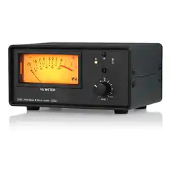
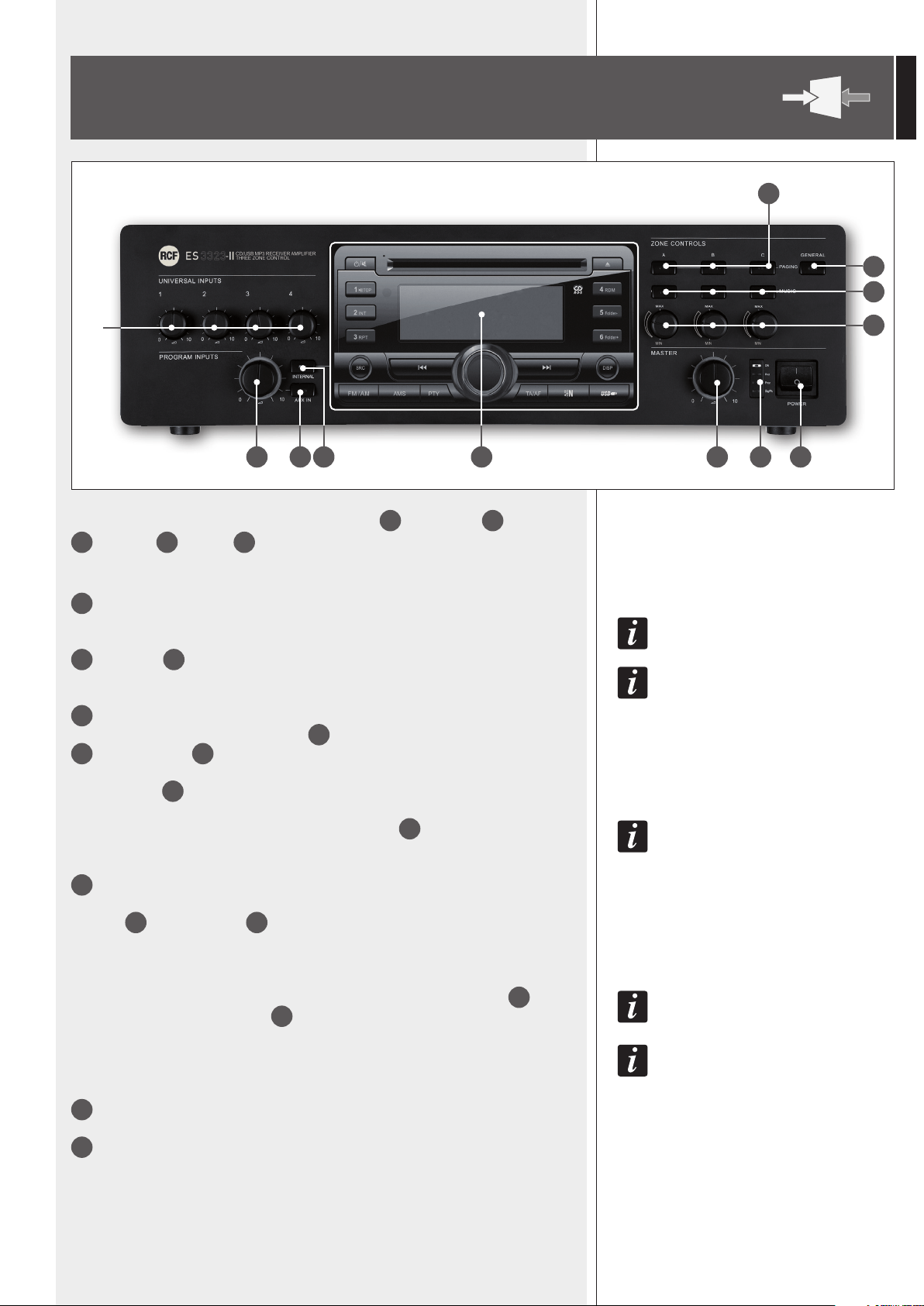
FRONT PANEL
1
10
9
11
12
8765432
1
Volume controls for each universal input (1, 2, 3, 4)
NOTE: UNUSED CHANNELS SHOULD ALWAYS BE TURNED FULLY COUNTERCLOCKWISE (TO 0).
2
AUX INPUT
21
volume control
NOTE: TURN FULLY COUNTERCLOCKWISE (TO 0) IF THE AUX INPUT IS NOT USED.
3
AUX IN button (with LED)
It turns on (LED is lit) / off the AUX INPUT
21
to the internal amplier and the PRE OUT
23
and MUSIC OUT
26
audio outputs.
If activated, the CD/USB – MP3 player / tuner signal is not sent to the internal amplier
(the INTERNAL
4
button LED turns off).
THE AUX INPUT SIGNAL IS ALWAYS SENT TO THE MUSIC ON HOLD
24
OUTPUT (THAT IS NOT AFFECTED
BY THE AUX IN BUTTON).
4
INTERNAL button (with LED)
It turns on (LED is lit) / off the CD/USB – MP3 / tuner to the internal amplier and the
PRE OUT
23
and MUSIC OUT
26
audio outputs.
If activated, the AUX INPUT signal is not sent to the internal amplier (the AUX IN button
LED turns off).
THE CD/USB MP3 PLAYER / TUNER SIGNAL IS ALWAYS SENT TO THE INTERNAL PROGRAM
22
OUTPUT
(
THAT IS NOT AFFECTED BY THE INTERNAL
4
BUTTON).
IT TAKES 10 SECONDS (AFTER PRESSING EITHER THE AUX IN OR INTERNAL BUTTON) TO STORE THE LAST
SELECTION.
5
CD/USB – MP3 player and tuner (read the relevant manual section).
6
Internal amplier MASTER volume control
NOTE: ALL AUDIO OUTPUTS VIA RCA CONNECTORS (INTERNAL PROGRAM, MUSIC ON HOLD, PRE
OUT, MUSIC OUT, PAGING OUT) ARE NOT AFFECTED BY THE MASTER VOLUME CONTROL.
IMPORTANT: after pressing a button (AUX IN
3
, INTERNAL
4
, GENERAL
9
, PAGING
10
, MUSIC
11
), the implementation of the new conguration
will take about 10 seconds.
8
ENGLISH
7
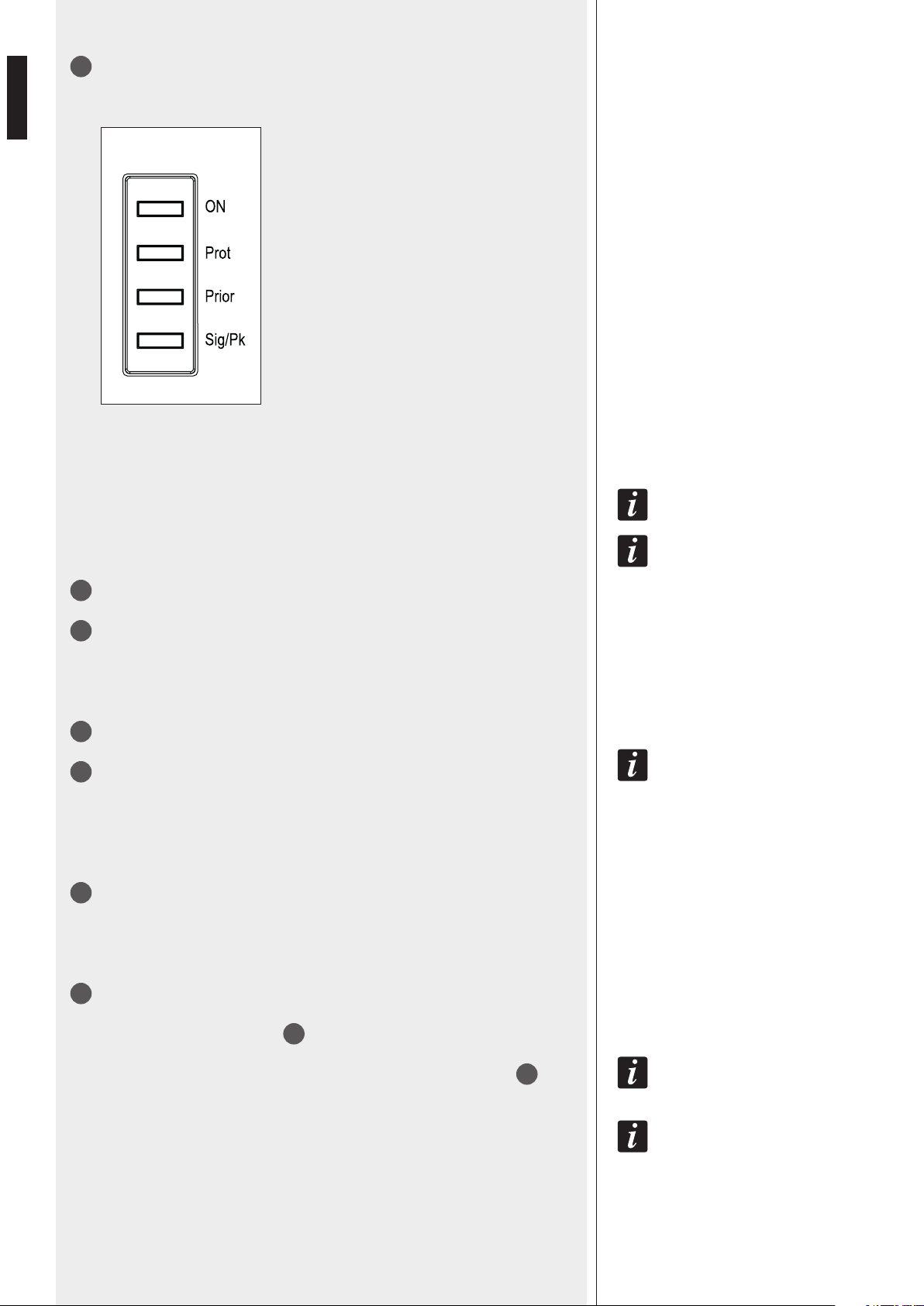
LEDs
ON green: the device is switched on
PROT red: overload protection
orange: thermal protection
PRIOR yellow: priority event in progress (VOX
function, command, SEQ. COMMAND.)
SIG/PK green:
the signal level is higher than – 15 dB
green + red:
the signal level is in the 0 ÷ +2 dB range
red: the signal level is equal or higher than +3 dB
0 dB = SIGNAL LEVEL THAT ALLOWS TO GET THE AMPLIFIER MAXIMUM POWER.
THE INTERNAL ‘LIMITER’ CIRCUIT HELPS TO AVOID THE AMPLIFIER OVERLOADING, YET IT IS ADVISABLE TO REDUCE
THE MASTER VOLUME (OR A SINGLE CHANNEL VOLUME WHERE A ‘TOO HIGH’ SIGNAL IS PRESENT) WHEN THE
SIG/PK LED IS CONTINUOUSLY INDICATING RED.
8
Main POWER switch (0 = off; I = on)
9
GENERAL button
If activated, it precongures general paging (to all the 3 zones) with the ‘override’
function.
‘OVERRIDE’ MEANS THAT AUDIO SIGNALS ARE SENT WITHOUT BEING AFFECTED BY THE 3 ZONE ATTENUATORS
12
.
10
PAGING buttons (one per each zone)
If activated, each button precongures its respective zone (for either the input 1 or 4
only) to be paged.
When ES 3323 is operating in the dual amplier mode and with no priority event in
progress, the 3 PAGING buttons send the mix of inputs 1, 2, 3, 4 to their respective zones.
11
MUSIC buttons (one per each zone)
If activated, each button sends either the music (internal player / AUX INPUT) or the mix
of all inputs (when no priority event is in progress and ES 3323 is operating in the single
amplier mode) to its respective zone.
12
Zone attenuators (one per each zone)
Each attenuator controls the output power in its respective zone separate loudspeaker
output (70 V / 100 V ZONE OUTPUTS
33
).
THE 3 ATTENUATORS DO NOT CONTROL THE OUTPUT POWER OF THE COMMON DIRECT OUTPUTS
34
.
PRIORITY EVENTS WITH ‘OVERRIDE’ (E.G. AN IMPORTANT ANNOUNCEMENT THAT NEEDS TO BE SENT AT ITS MAX.
VOLUME LEVEL, EVEN IN ZONES WHERE THE OUTPUT POWER IS REDUCED BY ATTENUATORS) ARE ALWAYS SENT WITH
THEIR MAX. (AVAILABLE) VOLUME, REGARDLESS OF THE ATTENUATOR SETTINGS.
9
ENGLISH
13
2 RJ 45 sockets (channels 2 and 3) to connect either:
- A single BM 3001 paging microphone only
- Or a single BM 3003 (3-zone) paging microphone
- Or a daisy-chain made of max. 12 BM 3003, by using an additional power supply unit.
NOTE ABOUT THE SETTING OF THE DIP-SWITCHES 3 AND 4 (SEE R): WHEN CONNECTING A BM 3001, SET THE
‘LINE WITH PHANTOM’ MODE (BOTH DIP 3 AND 4 ON); WHEN CONNECTING 1 OR MORE BM 3003, SET
THE ‘LINE’ MODE (BOTH DIP 3 AND 4 OFF).
14
Antenna input (the antenna is necessary when using the tuner).
15
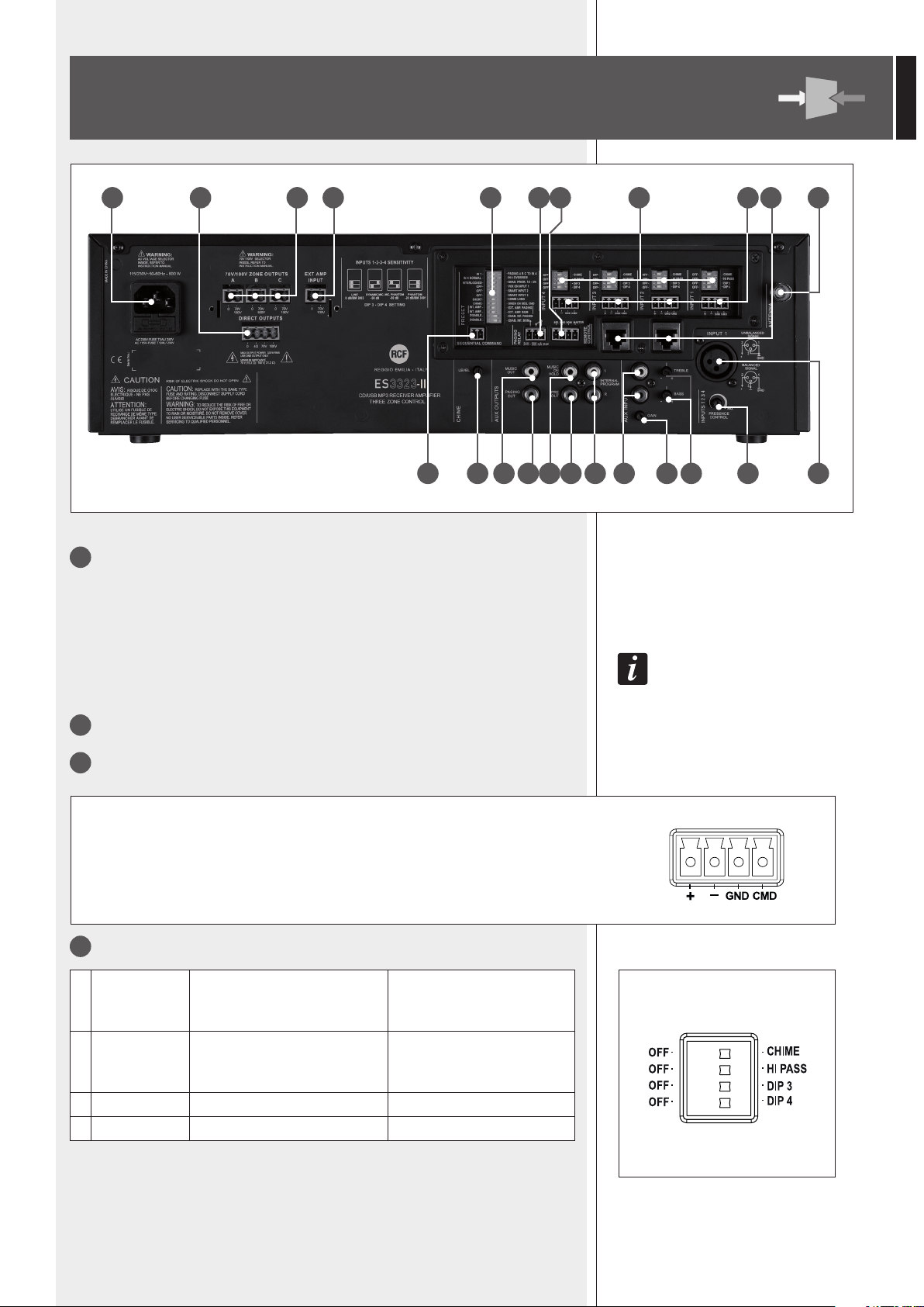
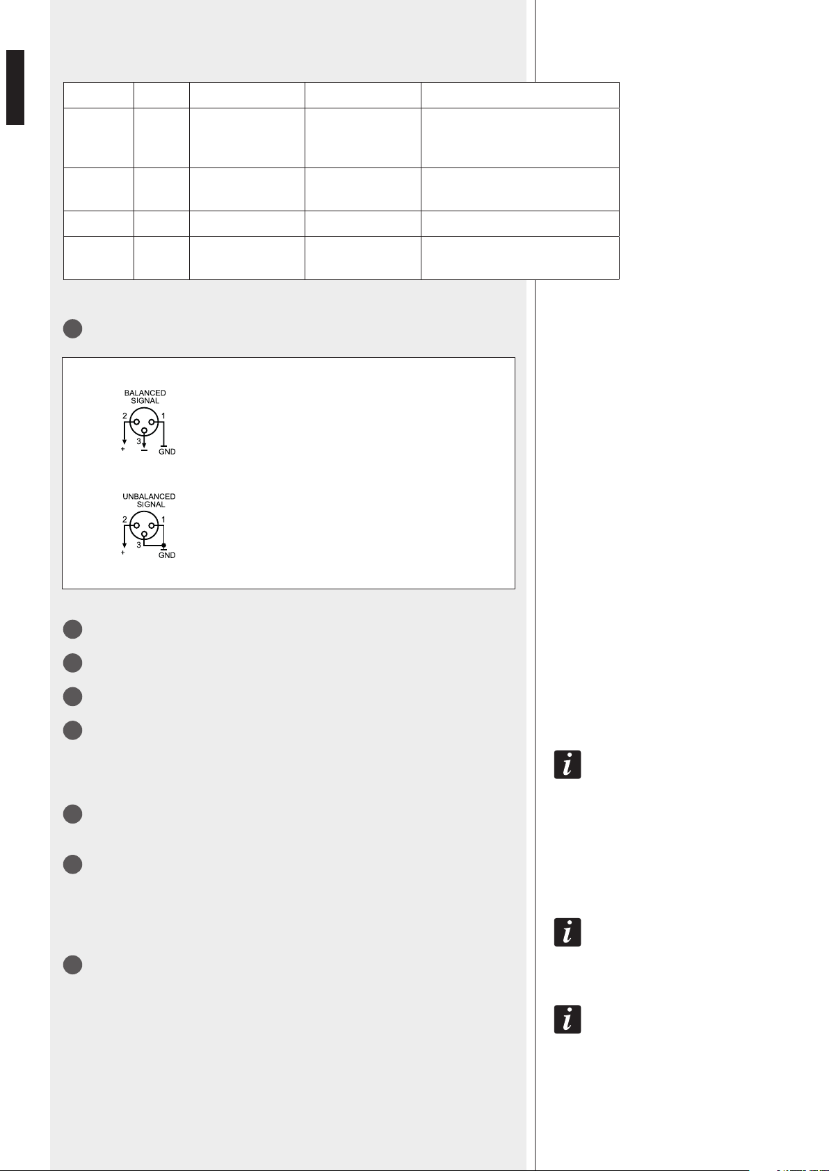
4 balanced audio inputs (channels 1, 2, 3, 4) with sockets for removable connectors.
+ Hot audio input
– Cold audio input
GND ground
CMD command – priority access when connected to ground
1 OFF – CHIME OFF: the chime is disabled.
CHIME: (ON) the chime will
be played as soon as a priority
command is activated.
2 OFF – HI PASS
OFF: the audio hi-pass lter
is not inserted (at frequency
response).
HI PASS: (ON) the audio
hi-pass filter is inserted.
3 OFF – DIP 3 OFF: see the next table. DIP 3: (ON) see the next table.
4 OFF – DIP 4 OFF: see the next table. DIP 4: (ON) see the next table.
16
Each channel has 4 dip-switches:
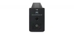
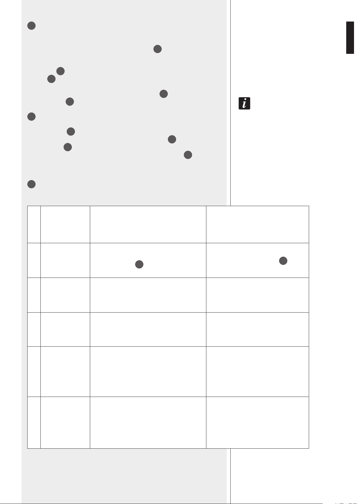
REAR PANEL
35 34 33 32 27 30 31 16 15 13 14
171819202122232425262829
10
ENGLISH
Dip-switch 3 and 4 settings:
DIP 3 DIP 4 MODE INPUT SENSITIVITY USE (EXAMPLES)
OFF OFF LINE 0 dBu
BM 3003 paging microphones,
CD/MP3 players, tuners, message
players, phone systems
ON ON
LINE with
PHANTOM
– 20 dBu BM 3001 paging microphones
ON OFF MIC. – 50 dBu Dynamic microphones
OFF ON
MIC. with
PHANTOM
– 50 dBu Electret microphones
17
Channel no.1 XLR input:
18
PRESENCE CONTROL (f = 2.15 kHz) common for all the channels 1, 2, 3, 4.
19
AUX INPUT TREBLE and BASS controls.
20
AUX INPUT GAIN control.
21
AUX INPUT with dual RCA connector.
THE TWO CHANNELS OF THE STEREO SOURCE CONNECTED TO THE AUX INPUT ARE SUMMED INTERNALLY
(TO GET A MONO SIGNAL).
22
INTERNAL PROGRAM stereo audio output with dual RCA connector (L: left channel,
R: right channel) that sends the direct CD/USB – MP3 player and tuner signal.
23
PRE OUT audio output (with RCA connector) that sends the same signal routed to
the internal amplier (signal that can be either a single source with priority or the mix of
all the channels 1, 2, 3, 4 and the selected music source).
THE OUTPUT PRE OUT MAY BE USEFUL TO CONNECT ADDITIONAL EXTERNAL AMPLIFIERS.
24
MUSIC ON HOLD audio output (with RCA connector) that sends a mono signal of the
source connected to the AUX INPUT.
EITHER THE MUSIC ON HOLD OUTPUT (IF AN EXTERNAL MUSIC SOURCE HAS BEEN CONNECTED TO THE AUX
INPUT) OR THE INTERNAL PROGRAM OUTPUT CAN BE USED FOR THE CONNECTION TO A TELEPHONE
SYSTEM (IN ORDER TO HAVE THE ‘MUSIC ON HOLD’ FUNCTION).
Balanced connection
+ hot
– cold
GND ground
Unbalanced connection
11
ENGLISH
25
PAGING OUT audio output (with RCA connector)
It sends either the mix of the channels 1, 2, 3, 4 (with no priority events in progress) or
the only input (1 ÷ 4) with priority or the chime (triggered by any priority command, if
enabled) or the tone set for the SEQUENTIAL COMMAND
29
.
Use this output to connect the additional amplier (if this is assigned for paging and/or
the mix of inputs 1÷4).
The MASTER
6
volume and the remote one (if connected to REMOTE CONTROL
MASTER
31
) do not affect this output.
INPUT 1 ÷ 4 SIGNAL LEVELS DEPEND ON THE RESPECTIVE CHANNEL VOLUMES
1
, THE CHIME LEVEL DEPENDS ON
THE CHIME LEVEL
28
CONTROL ON THE REAR PANEL; THE SIREN LEVEL IS FIXED.
26
MUSIC OUT audio output (with RCA connector)
It sends the audio signal of the selected music source (internal CD/USB – MP3 player and
tuner, AUX INPUT
21
, off).
The level depends on both the internal player/ tuner (or the AUX
2
volume and its
respective GAIN
20
control on the rear panel when selecting the AUX INPUT) and the
remote control potentiometer (if connected to REMOTE CONTROL BGM
31
).
Use this output to connect the additional amplier (if this is assigned for the music).
27
12 dip-switches PRESET (system / priority options):
1.
IN 1 –
PAGING A B C TO
IN 4
IN 1: the 3 PAGING zone selection buttons (on the
front panel) are assigned to the channel 1.
PAGING A B C TO IN 4: the 3 PAGING zone
selection buttons (on the front panel) are
assigned to the channel 4.
2.
IN 4 NORMAL –
IN 4 OVERRIDE
IN 4 NORMAL: the channel 4 volume is affected
by the attenuators
12
during its priority.
IN 4 OVERRIDE: the channel 4 volume is
not affected by the attenuators
12
during
its priority.
3.
INTERLOCKED –
GRAD. PRIOR.
1/2-3/4
INTERLOCKED: interlocked priority mode
GRADUATED PRIORITY 1/2–3/4: graduated
priority mode
4.
OFF –
VOX ON INPUT 1
OFF: the channel 1 VOX function is off.
VOX ON INPUT 1: the channel 1 VOX
function is on (automatic priority when a
signal is detected on the audio INPUT 1).
5.
OFF –
SMART INPUT 2
OFF: the channel 2 priority is held only if the
relevant command is still present (‘push’ mode).
NOTE: SET TO OFF IF 1 OR MORE BM 3003 PAGING
MICROPHONES ARE CONNECTED TO THE INPUT 2.
SMART INPUT 2: the channel 2 priority is
switched on / off by every impulse of the
relevant command (‘toggle’ mode).
6.
OFF –
SMART INPUT 3
OFF: the channel 3 priority is held only if the
relevant command is still present (‘push’ mode).
NOTE: SET TO OFF IF 1 OR MORE BM 3003 PAGING
MICROPHONES ARE CONNECTED TO THE INPUT 3.
SMART INPUT 3: the channel 3 priority is
switched on / off by every impulse of the
relevant command (‘toggle’ mode).
12
ENGLISH
7.
SHORT –
CHIME LONG
SHORT: short chime. CHIME LONG: long chime.
8.
CHIME –
SIREN ON SEQ.
CMD
CHIME: the chime (selected by the
dip-switch no.7) is continuously
played when the ‘SEQUENTIAL
COMMAND’ is triggered.
SIREN ON SEQ.CMD: an alarm
tone is continuously played when
the ‘SEQUENTIAL COMMAND’ is
triggered.
9.
INT. AMP. –
EXT. AMP. PAGING
See the next table (dip-switches 9
and 10) INT. AMP.: dip-switch 9 OFF
See the next table (dip-switches 9
and 10) EXT. AMP. PAGING: dip-
switch 9 ON
10.
INT. AMP. –
EXT. AMP. BGM
See the next table (dip-switches 9
and 10) INT. AMP.: dip-switch 10
OFF
See the next table (dip-switches 9
and 10) EXT. AMP. BGM: dip-switch
10 ON
11.
DISABLE –
ENAB. INT. PAGING
DISABLE: (OFF) it mutes the input
1÷4 signals, the chime and the
siren to the internal amplier.
ENAB. INT. PAGING: (ON) it enables
the input 1÷4 signals, the chime
and the siren to the internal
amplier.
12.
DISABLE –
ENAB. INT. BGM
DISABLE: (OFF) it mutes the
selected music source to the
internal amplier.
ENAB. INT. BGM: (ON) it enables the
selected music source to the internal
amplier.
DIP 9 DIP 10 OPERATION MODE
OFF OFF ES 3323 operates as a single amplier for both paging and music.
ON OFF Dual amplication: ES 3323 for music, the additional external amplier for paging.
OFF ON Dual amplication: ES 3323 for paging, the additional external amplier for music.
ON ON ES 3323 operates as a single amplier for both paging and music.
DIP-SWITCH 11 and 12 SETTING DIP 11 DIP 12
No additional external amplifier (ES 3323 operates as a single amplifier). ON ON
Dual amplification: ES 3323 for music, the additional external amplifier for
paging.
OFF ON
Dual amplification: ES 3323 for paging, the additional external amplifier
for music.
ON OFF
ANY SELECTION (THROUGH DIP-SWITCHES) IS ONLY ACCEPTED AND GETS ACTUAL AT THE END OF A PRIORITY EVENT
(FOR INSTANCE, A MIC. CALL) OR WHEN SWITCHING THE DEVICE ON.
13
ENGLISH
28
CHIME LEVEL (a trimmer adjustable by using a small screwdriver).
29
SEQUENTIAL COMMAND with removable connector (activated when the 2 pins
are short-circuited) to send continuously (with max. volume) either the chime (selected
through the dip-switch 7 PRESET
27
) or an alarm tone (selected through the dip-switch
8 PRESET
27
).
30
Internal relay contacts (3 pole removable connector)
The internal relays switches when a priority command is present.
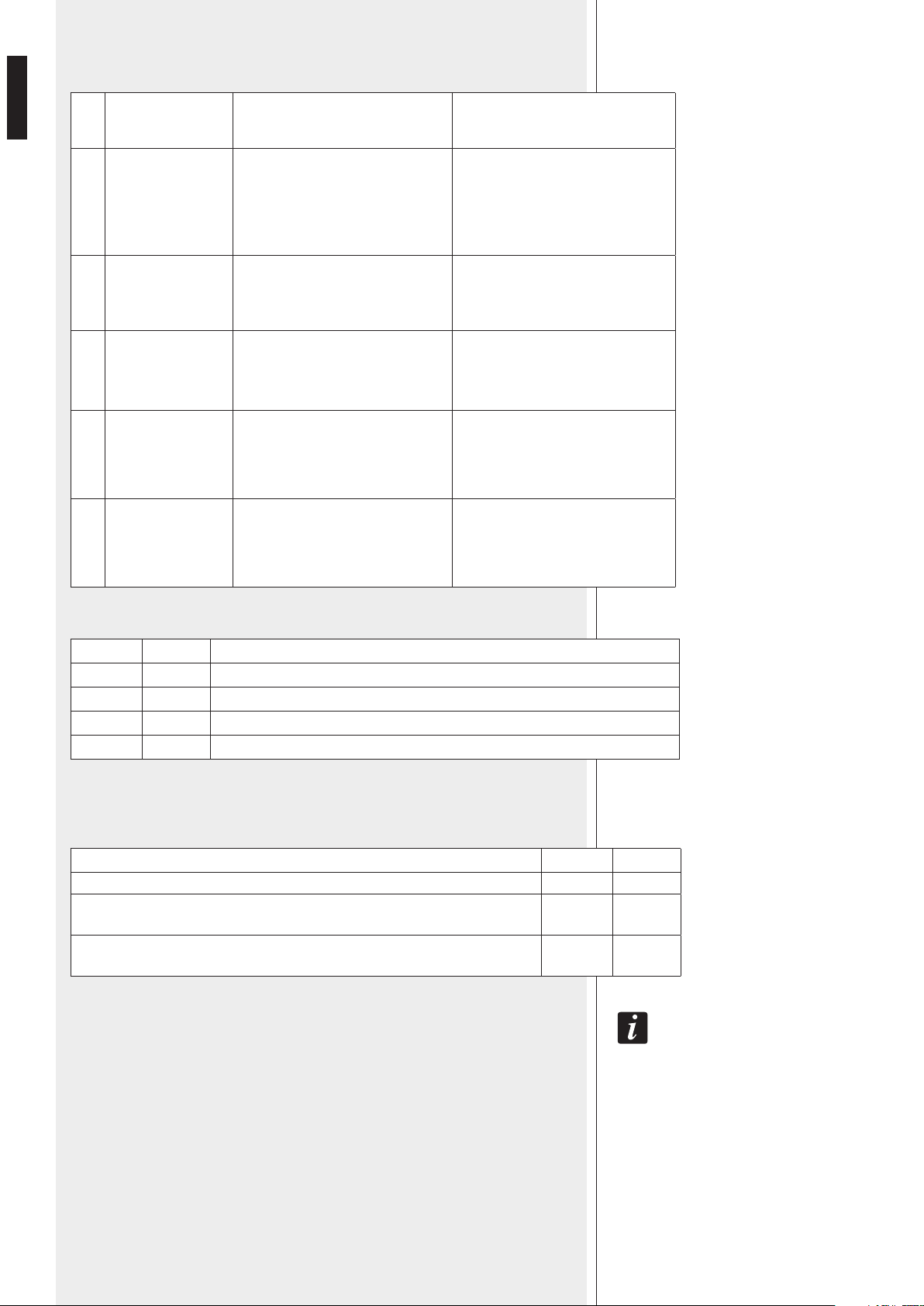
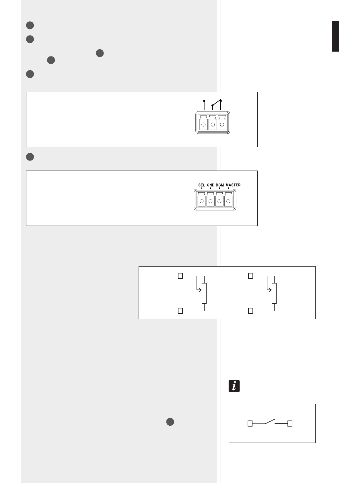
31
REMOTE CONTROL terminal
SEL: music source selection (when linked to ground)
GND: common ground
BGM: music volume
MASTER: master volume
1 2 3
SEL GND
MASTER
GND
10 kΩ ÷
100 kΩ
BGM
GND
10 kΩ ÷
100 kΩ
1 – normally open
2 – common
3 – normally closed
Max. voltage: 24 V; max. current: 0.5 A.
REMOTE VOLUME CONTROL
The MASTER and BGM remote volume controls are independent. Insert a potentiometer
between the respective contact and the ground.
The potentiometer nominal value affects the
operating range (referring to the front panel
settings): the higher the value, the wider the
adjustable range.
Its value can be typically from 10 kΩ to 100 kΩ,
the optimal action is obtained with an inverse
logarithmic curve potentiometer, but it is also
acceptable a linear response one.
The music remote control is relative to the activated music source (either internal or
external).
The maximum range that can be obtained is 40 dB (relative to the signal adjusted by the
main settings).
MUSIC SOURCE REMOTE SELECTION
It is obtained by connecting a push-button between the SEL e GND contacts.
The selection is cyclic: CD/USB – MP3 player and tuner, AUX INPUT
21
, no music.
IMPORTANT: IF A REMOTE CONTROL POTENTIOMETER IS NOT FORESEEN, IT IS NECESSARY TO SHORT-
CIRCUIT THE RESPECTIVE CONTACT TO GROUND (THROUGH A WIRE), OTHERWISE THE MASTER VOLUME
AND / OR THE BGM VOLUME ARE SET TO ZERO (MUTED).
14
ENGLISH
32
EXT AMP INPUT for a 100 – 70 V constant voltage line coming from the additional
external amplier output.
33
Separate 100 – 70 V constant voltage ZONE OUTPUTS (one per zone) to connect
loudspeakers. See the section ‘Loudspeaker connection’.
34
DIRECT OUTPUTS (not affected by zone selection, max. 320 W) to loudspeakers
(100 / 70 V constant voltage line).
The low impedance output (min. 4 Ω) allows to connect a monitor loudspeaker (max.
power: 2 W).
35
Mains connector with fuse
Before connecting the power cable, verify that the apparatus voltage (230 or 115 V ac)
corresponds to the available mains supply.
NOTE: THE FUSE TYPE IS MARKED ON THE REAR PANEL (BELOW THE MAINS CONNECTOR).
ES 3323 CAN OPERATE IN 3 DIFFERENT MODES:
1. SINGLE: as stand-alone amplier for both paging and music.
The music is not held in zones not paged during a priority event in progress.
2. DUAL AMPLIFICATION ‘A’: ES 3323 is linked to an additional external amplier (i.e.
RCF UP 2321) for paging only (while the internal one amplies the music only).
3. DUAL AMPLIFICATION ‘B’: ES 3323 is linked to an additional external amplier (i.e.
RCF UP 2321) for music only (while the internal one is for paging only).
‘VOX’ IS AN INTERNAL CIRCUIT THAT AUTOMATICALLY ACTIVATES THE CHANNEL 1 PRIORITY WHEN A SIGNAL IS
DETECTED ON THE AUDIO INPUT 1.
OPERATION WITH NO PRIORITY EVENT IN PROGRESS
(after turning the amplier on or when a priority command ends).
If no priority command is present (including VOX and SEQUENTIAL COMMAND
29
), all
the channels 1, 2, 3, 4 and the music source are mixed together.
The music source can be:
- The internal CD/USB – MP3 player and tuner.
- The AUX INPUT signal.
- Disabled.
The mixed signal is only sent to zones selected through the 3 MUSIC [11] buttons on the
front panel.
The master volume is adjusted by the MASTER
6
control.
The volume of each input 1 ÷ 4 is adjusted separately by the controls 1, 2, 3, 4
1
.
The music volume depends on either the control of the CD/USB – MP3 player and tuner (if
selected) or the AUX IN volume control
2
on the front panel.
The AUX INPUT
21
volume also depends on the rear panel GAIN
20
control.
THE MUSIC SOURCE (INTERNAL OR EXTERNAL) CAN BE ACTIVATED / MUTED THROUGH THE FRONT PANEL BUTTONS
3
4
.
OPERATION MODES
SINGLE MODE OPERATION
15
ENGLISH
PROCEED AS FOLLOWS:
a. Ensure the dip-switches 9 and 10 PRESET
29
are both set to OFF (or both set to ON).
b. Ensure the dip-switches 11 and 12 PRESET
29
are both set to ON.
c. Adjust (momentarily) the MASTER
6
control at (circa) half volume.
d. Choose a music source (internal or AUX IN) through the front panel buttons
3
4
;
e. Select zones where to send the music through the 3 MUSIC
11
buttons.
f. Adjust the music volume (through either the CD/USB – MP3 player and tuner volume or
the AUX IN
2
control).
g. If loudspeakers are connected to the ZONE OUTPUTS
33
, temporarily set the 3
attenuators
12
to MAX. (not necessary when using DIRECT OUTPUTS
34
).
h. Adjust the MASTER volume to get the desired level.
i. If necessary, attenuate the output level of each zone by using its respective attenuator
12
.
j. Adjust the channel 1 ÷ 4 volumes
1
if these inputs are connected.
NOTE: HERE ABOVE IT IS ASSUMED THAT REMOTE CONTROL POTENTIOMETERS ARE NOT CONNECTED OR, IF
CONNECTED, THESE ARE TEMPORARILY SET TO THEIR MAX. LEVEL.
THE PRIORITY COMMAND IS GOT:
- Through channels 1 ÷ 4, by connecting (in the removable connectors
15
) the respective
contact CMD to ground (GND); the priority remains activated if the link is stable (but the
input 2 and 3 SMART function).
- By the channel 1 through its VOX function (if enabled).
- Through BM 3003 / BM3001 paging microphones connected to the ‘RJ’ port
13
of
the channels 2 and 3, considering that removable connectors (for priority commands
and audio signals) cannot be used if lines are engaged (in order to avoid malfunction).
- By the SEQUENTIAL COMMAND
29
.
If any priority command is in progress (including VOX), only the channel with priority (among
inputs 1 ÷ 4, BM 3003 / BM 3001 paging microphones, SEQUENTIAL COMMAND) is sent
to the DIRECT OUTPUTS
34
for loudspeakers.
The selected music source and the other inputs are muted (even on ZONE OUTPUTS
33
).
When a priority event is in progress, the ‘PRIOR’ LED
7
gets lit and the audio signal sent
to the PRE OUT
23
only includes the channel with priority.
PRIORITY
16
ENGLISH
DIP 3 MODE
INTERLOCKED INTERLOCKED
Only the first priority command of
channels 1 ÷ 4 is accepted (also
channel 1 VOX, if enabled through the
dip-switch 4 PRESET
27
). Any other
priority command will not be accepted
until the previous one is removed.
NOTE: THE ONLY EVENT THAT CAN ALWAYS
BE AC TI VAT ED L AT ER (AN D OV ER RI DE S A
PR EV IO US P RI OR I TY ) IS T HE SEQUENTIAL
COMMAND
29
.
GRAD. PRIOR.
1/2-3/4
GRADUATED
PRIORITY
A priority command having a higher level
can override the previous one.
The priority levels are:
1. (highest) SEQUENTIAL COMMAND
2. channel 1 (including VOX)
3. channels 2 and 3 (interlocked each other)
4. channel 4
THE PRIORITY MODE (INCLUDING THE VOX FUNCTION) IS SET BY THE DIP-
SWITCH 3 PRESET
27
:
As soon as a priority event ends, the initial state will be restored (the channels 1, 2, 3, 4
and the selected music source will be mixed together, unless another priority event is in
progress).
About selective paging to A, B, C zones (separated ZONE OUTPUTS
33
), it is necessary
to consider:
- The state of front panel PAGING
10
and GENERAL
9
buttons.
- The setting of the dip-switches 1 and 2 PRESET
27
on the rear panel.
- The device requiring the priority (for instance, BM 3001 paging microphones can make
general calls only, BM 3003 can make selective calls).
The 3 zone attenuators
12
can adjust the level on the separate 70 V / 100 V ZONE OUTPUTS
33
, but the DIRECT OUTPUTS
34
(and the additional external amplier, if present) are
not affected by these controls.
The audio signal of an event with priority and ‘override’ is always sent to the separate
outputs with its. max. set volume, without being controlled by the zone attenuators.
The audio signal level of an event with normal priority is also adjusted by the zone
attenuators.
‘OVERRIDE’ MEANS THAT AUDIO SIGNALS ARE SENT WITHOUT BEING AFFECTED BY THE 3 ZONE
ATTENUATORS
12
.

17
ENGLISH
THE 3-ZONE SELECTIVE PAGING IS CONTROLLED ACCORDING TO THE
FOLLOWING RULES:
1. If the GENERAL button
9
is on, when the priority is got by one of the channels 1
÷ 4 or a BM3001 paging microphone, paging will be general (‘all call’) in the OVERRIDE
mode (regardless of any other setting).
2. When the priority is got by the channels 2 – 3 (or by a BM 3001 paging microphones
connected to either the input 2 or 3) or the SEQUENTIAL COMMAND
29
, paging (/ the
alarm tone) will be general (‘all call’) in the OVERRIDE mode (regardless of any other
setting).
3. From BM 3003 paging microphones (connected to the inputs 2 and 3), users can
always select the zones to be paged (OVERRIDE mode).
4. When the priority is got by the channel 1, paging will be always in the OVERRIDE
mode; the zone selection depends on both the dip-switch 1 of the PRESET group
27
and
the front panel PAGING buttons
10
:
- If the DIP 1 is set to ‘PAGING A B C TO IN 4’, paging is always general (regardless of the
PAGING button selection).
- If the DIP 1 is set to ‘IN 1’, paging is selective to the zones chosen through the PAGING
buttons (note: if no zone is selected, paging is only sent to the DIRECT OUTPUTS
34
).
5. When the priority is got by the channel 4, paging can be either normal or in the
OVERRIDE mode, according to the dip-switch 2 setting of the PRESET group
27
(and
also the front panel GENERAL button
9
). The zone selection depends on both the dip-
switch 1 (PRESET group
27
) and the front panel PAGING buttons
10
:
- If the DIP 1 is set to ‘IN 1’, paging is always general (regardless of the PAGING button
selection).
- If the DIP 1 is set to ‘PAGING A B C TO IN 4’, paging is selective to the zones chosen
through the PAGING buttons (note: if no zone is selected, paging is only sent to the
DIRECT OUTPUTS
34
).
18
ENGLISH
DUAL AMPLIFICATION ‘A’
TABLE OF CORRELATION BETWEEN PRIORITY COMMANDS AND ACTIVATED
ZONES:
In this mode, ES 3323 is linked to an additional external amplifier (i.e. RCF UP 2321)
for paging only (while the internal one amplifies the music only).
ES 3323: MUSIC EXTERNAL AMPLIFIER: PAGING
See the manual section ‘Additional external amplifier connection’, paragraph ‘A’.
IF NO PRIORITY EVENT IS IN PROGRESS:
- The music (internal or external player) is sent to all the zones having the MUSIC button
11
turned on (or both the MUSIC
11
and PAGING
10
buttons turned on).
- The mix of all the channels 1 ÷ 4 (through the external amplier) is sent to all the zones
having (only) the PAGING button
11
turned on.
When a priority event is in progress (i.e. an announcement), the signal having the
priority is sent to the 3 zones by following the rules listed in the previous manual
section ‘Single mode operation’, but the OVERRIDE function (as the level of
the signal having the priority depends on the external amplier volume
setting).
The music is held (if activated) in the zone(s) not affected by the event
with priority.
DURING A PRIORITY EVENT, ONLY THE SIGNAL WITH PRIORITY (AND NOT THE MIX OF ALL THE CHANNELS 1 ÷
4)
IS SENT TO THE ZONE(S) HAVING THE (ONLY) PAGING BUTTON
11
TURNED ON.
PRIORITY
COMMAND
Dip-switch 1
(Paging buttons
to IN 1 / IN 4)
Dip-switch 2
(IN 4 override)
General
button
Activated zones
mode
(normal/override)
BM 3
003 PAGING MIC.
Selected zones by
BM 3003 paging mic.
override
INPUT 1
IN 4 all
override
IN 1
ON all
OFF
Selected zones through
Paging buttons
P
INPUT 2,
INPUT 3,
BM 3001
PAGING MIC.
all override
INPUT 4
IN 4
ON all
override
ON
OFF
Selected zones through
Paging buttons
P
OFF normal
IN 1
ON
all
override
ON
OFF
OFF normal
SEQUENTIAL
COMMAND
all override

19
ENGLISH
In this mode, ES 3323 is linked to an additional external amplier (i.e. RCF UP 2321) for
music only (while the internal one is for paging only).
ES 3323: PAGING EXTERNAL AMPLIFIER: MUSIC
See the manual section ‘Additional external amplier connection’, paragraph ‘B’.
IF NO PRIORITY EVENT IS IN PROGRESS:
- The music (internal or external player, ES 3323 sends the signal to the external amplier)
is present in all the zones having the respective MUSIC button
11
turned on (or both
MUSIC
11
and PAGING [10] buttons turned on).
- The mix of all the channels 1 ÷ 4 (through the ES 3323 internal amplier) is sent to all
the zones having (only) the PAGING button
11
turned on.
When a priority event is in progress (i.e. an announcement), the signal having the priority
is sent to the 3 zones by following the rules listed in the previous manual section ‘Single
mode operation’, including the OVERRIDE mode.
The music is held (if activated) in the zone(s) not affected by the event with
priority.
The attenuators
12
control the paging levels only (if the OVERRIDE function is not
activated).
ES 3323 has 2 audio outputs (PAGING OUT
25
e MUSIC OUT
26
)and a (100 V / 70 V)
constant voltage input for the external amplier connection.
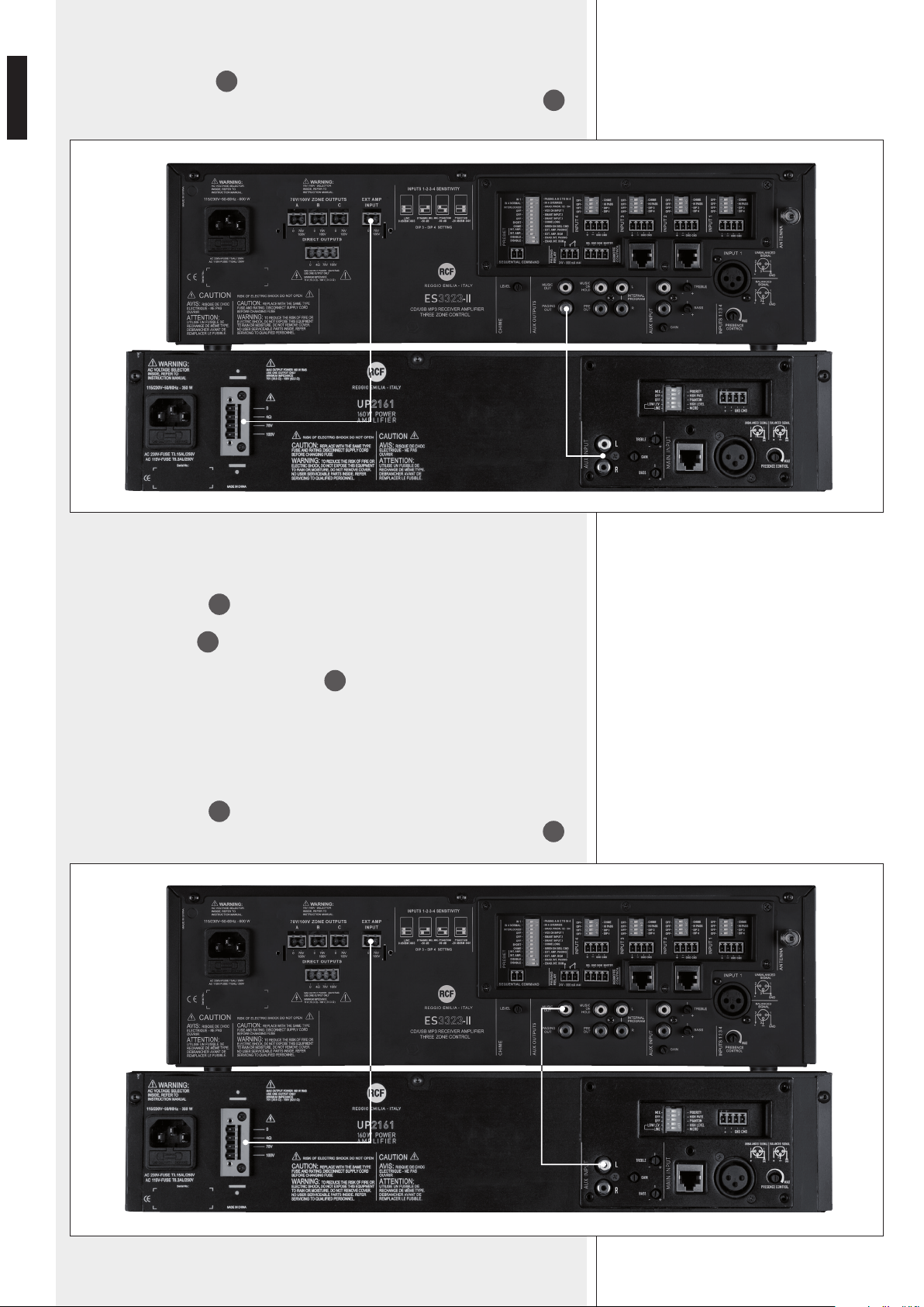
A) ES 3323: MUSIC EXTERNAL AMPLIFIER: PAGING
NECESSARY LINKS:
- Connect PAGING OUT
25
to the external amplier audio input.
- Connect the external amplier 100 V (/ 70 V) constant voltage output (for loudspeakers)
to EXT AMP INPUT
32
;
DIP-SWITCH SETTINGS (PRESET GROUP
27
):
- DIP 9 ON
- DIP 10 OFF
- DIP 11 OFF (to avoid that channel 1 ÷ 4 signals are mixed with the music)
- DIP 12 ON (music is sent to the internal amplier).
ADDITIONAL EXTERNAL AMPLIFIER
CONNECTION
DUAL AMPLIFICATION ‘B’
20
ENGLISH
B) ES 3323: PAGING EXTERNAL AMPLIFIER: MUSIC
NECESSARY LINKS:
- Connect MUSIC OUT
26
to the external amplier audio input.
- Connect the external amplier 100 V (/ 70 V) constant voltage output (for loudspeakers)
to EXT AMP INPUT
32
;
DIP-SWITCH SETTINGS (PRESET GROUP
27
):
- DIP 9 OFF
- DIP 10 ON
- DIP 11 ON (it enables the channel 1÷4 signals to the internal amplier)
- DIP 12 OFF (music is muted to the internal amplier).
EXAMPLE OF CONNECTION TO AN RCF UP 2321:
- Connect MUSIC OUT
25
to UP 2321 AUX INPUT
- Connect the UP 2321 (100 V / 70 V) constant voltage output to EXT AMP INPUT
32
.
EXAMPLE OF CONNECTION TO AN RCF UP 2321:
- Connect PAGING OUT
25
to UP 2321 AUX INPUT
- Connect the UP 2321 (100 V / 70 V) constant voltage output to EXT AMP INPUT
32
.
21
ENGLISH
SEQUENTIAL COMMAND
The SEQUENTIAL COMMAND
29
has the highest priority and starts (and keeps) playing
to all zones either the chime (short or long, set through the dip-switch 7 of the PRESET
group
27
) or the alarm tone (set through the dip-switch 8 of the PRESET group
27
) in
the OVERRIDE mode.
CHANNEL 2 - 3 ‘PUSH’ / ‘TOGGLE’ (‘SMART’) PRIORITY MODE
The dip-switches 5 and 6 of the PRESET group
27
, allow choice of priority mode for
channels 2 and 3 respectively between ‘push’ (the priority is held only if the command is
still present) and ‘toggle’ (the priority is switched on / off by every impulse of the command).
NOTE: THE CHOSEN PRIORITY MODE IS APPLIED TO BOTH BM 3001 PAGING MICROPHONES (IF PRESENT) AND
PRIORITY COMMANDS (OF REMOVABLE CONNECTORS), BUT NEVER TO BM 3003 PAGING MICROPHONES.
SET THE DIP-SWITCH 5 (FOR THE INPUT 2) AND/OR THE DIP-SWITCH 6 (FOR THE INPUT 3) OF THE PRESET
GROUP TO OFF IF BM 3003 PAGING MICROPHONES ARE CONNECTED.
FURTHER INFORMATION
4 DIP-SWITCH GROUP (PER EACH CHANNEL 1÷4)
For each channel, it is possible to set the input gain (with or without PHANTOM power
supply) on/off, insert / remove the high-pass lter and enable / disable the chime, which is
played on every priority event.
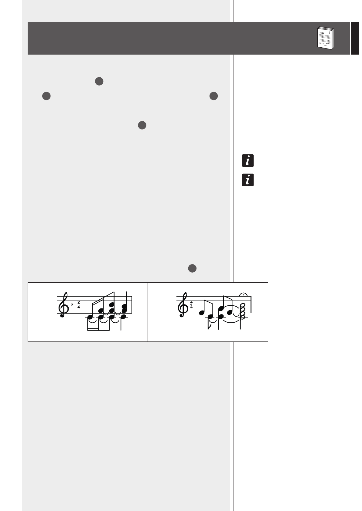
INFORMATION ABOUT THE CHIME
The chime is not played when using the channel 1 VOX function (a priority command is
needed to play the chime).
Its melody can be either short or long (dip-switch 7 of the PRESET group
27
.
When the chime is playing (a few seconds), in the single mode operation, the music
(internal or external through the AUX INPUT) is muted.
SETTING AUTOMATIC STORE
All settings by the front panel buttons are automatically stored after 10 seconds since the
last button pressure.
If a priority event is in progress, it is possible to change the state of each single button
(by pressing it), but the respective effect will be actually applied and stored only when the
priority event ends.
SHORT LONG
22
ENGLISH
RCF BM 3001 / BM 3003 PAGING MICROPHONES
RCF BM 3001 / BM 3003 PAGING MICROPHONES
Channels 2 and 3 have an input with RJ 45 socket, to which it is possible to connect 2
models of RCF paging microphones (not included):
- BM 3001 (for all calls only)
- BM 3003 (for 3-zone selective calls and ‘daisy-chain’ links of up to 12 paging
microphones in the same line).
Only one BM 3001 paging microphone can be connected to each RJ 45 input (max. 2:
one to the input 2, one to the input 3).
The BM 3001 operating mode and its priority depends on settings previously described.
IT IS POSSIBLE TO ASSIGN THE SMART FUNCTION TO EACH BM3001 PAGING MICROPHONE THROUGH THE DIP-
SWITCHES 5 (FOR THE INPUT 2) AND 6 (FOR THE INPUT 3) OF THE PRESET GROUP
27
.
ES 3323-II identies a BM3001 paging microphone through the ‘LINE with PHANTOM’
mode setting in the respective channel, therefore it is necessary to set the input dip-
switches 3 and 4
16
properly (both set to ON).
WHEN USING BM3003 PAGING MICROPHONES, TO EACH RJ 45 IT IS POSSIBLE
TO CONNECT:
- a single BM 3003 paging microphone (without any additional power supply unit)
- a ‘daisy-chain’ made of max.12 BM 3003 by inserting an additional power supply unit.
After connecting one or more BM 3003 paging microphones, set the dip-switches
3 and 4
16
of the respective input to the ‘LINE’ mode (both set to OFF).
BM 3003 paging microphones always operate in the SMART mode, so set (/ leave) the
dip-switch 5 (for the input 2) and 6 (for the input 3) of the PRESET group
27
(SMART
function) to OFF.
IT IS POSSIBLE TO CONNECT A BM 3001 TO AN RJ 45 INPUT AND ONE (OR
MORE) BM 3003 TO THE OTHER, SO IT IS ALLOWED TO HAVE:
- No paging microphone
- 1 x BM 3001
- 2 x BM 3001 (one per each input)
- max. 12 x BM 3003 (to one input only)
- max. 12 x BM 3003 (to an input) + 1 x BM 3001 (to the other input)
- max. 24 x BM 3003 (max. 12 per each input).
IMPORTANT: IT IS NOT ALLOWED TO CONNECT DIFFERENT PAGING MICROPHONE MODELS TO THE
SAME INPUT!
When BM 3003 paging microphones are linked (daisy-chain) in the same line, the rst
BM 3003 (that is directly connected to the ES 3323 amplier) does not need to be
powered by the additional power supply unit, which is necessary for all the others.
About paging microphone operation in details, refer to the respective user manuals.
When the chime is playing (if enabled), microphones are momentary muted.
Paging microphones can be disabled by events having a higher priority level than their
channels (2 and 3).
23
ENGLISH
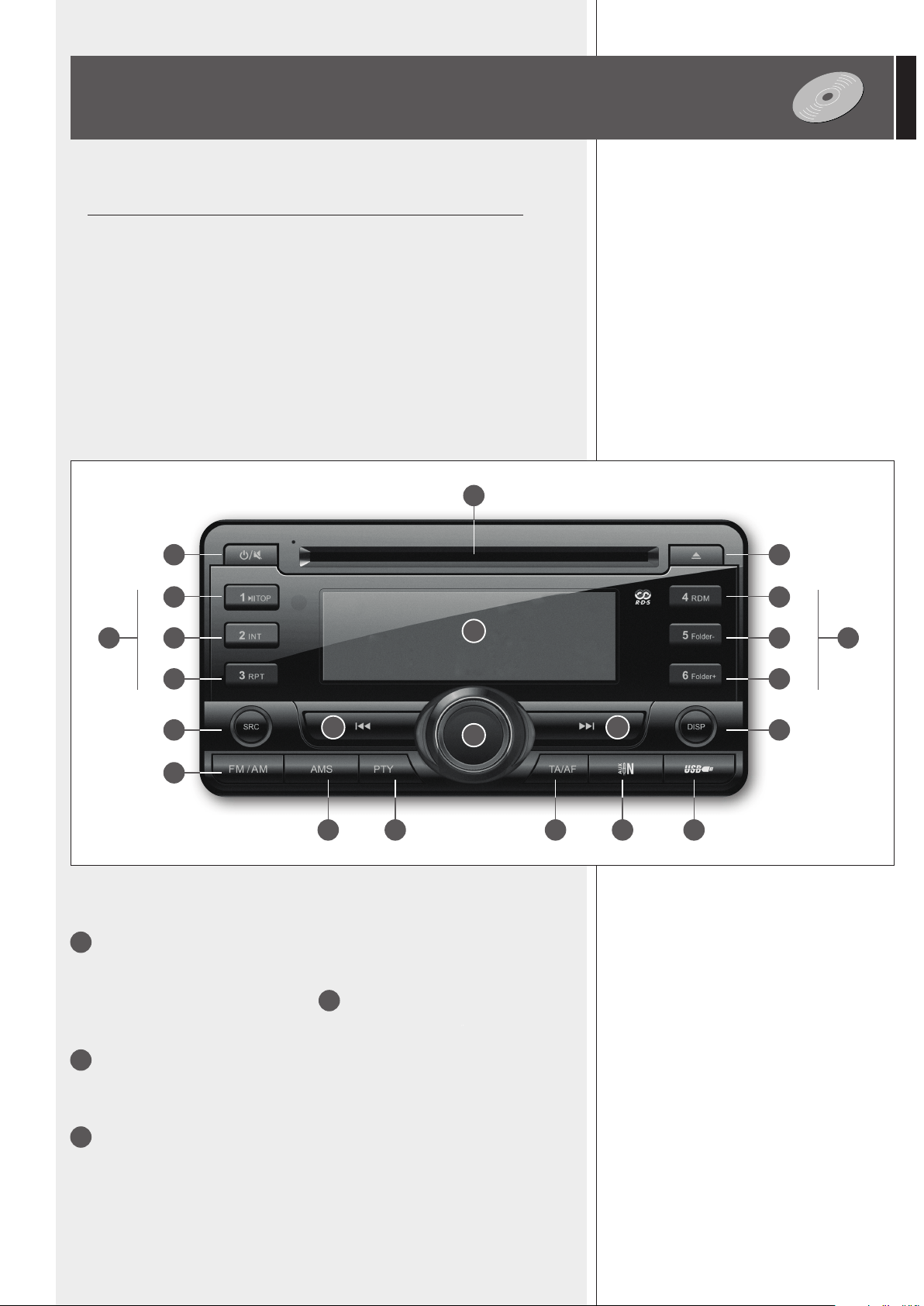
1
POWER ON/OFF – MUTE button.
If the player is off, press (and release) this button to turn it on.
If the player is on, press (and release) this button to mute it (“MUTE” is displayed).
Press it again (or rotate the volume control
4
to unmute it.
Press and hold (2 seconds) to turn off the player.
2
SRC (source) button: press (once or more times) to select the source among the tuner,
CD (when inserted), USB (if a USB ash drive is connected), AUX input, ‘Bluetooth’ devices
(if present and matched to the player).
3
FM/AM button: tuner band selection between FM (frequency modulation, 3 groups:
FM1, FM2, FM3) and AM (medium wave amplitude modulation, 2 groups: MW1, MW2).
NOTE SUI COMPACT DISC
- Use 12 cm audio CD, CD-R and CD-RW only. Never insert 8 cm (3-inch) CDs !
- Do not use damaged CDs (or having an irregular shape).
- Keep CDs clean and hold them always on their edges (without touching their unlabeled
surface). Wipe a dirty CD from the centre outward with a clean soft and dry cleaning
cloth. Do not use alcohol or solvents.
- Do not attach adhesive labels on CDs (and do not use CDs having adhesive labels).
- Put CDs in their cases when not used.
- Do not leave CDs close to heat sources, exposed to high temperatures or the direct
sunlight (for instance, inside a car).
- Some CD-R (recordable) / CD-RW (rewritable) types may not be read correctly.
CD/USB – MP3/WMA PLAYER AND TUNER
1 19
7 10
8
181715 1614
11
9 12
132
3
20 20
21
22
5 6
4
FRONT PANEL
FRONT PANEL

24
ENGLISH
4
Volume control (encoder) and push button to select parameters.
Turn it clockwise to turn the volume up of the player (only).
Turn it counterclockwise to turn the volume down.
When pushed, it changes the parameter to edit (by turning the control):
volume (VOL 0 ÷ 47) → bass (BAS -7 ÷ +7) → treble (TRE -7 ÷ +7) → balance (BAL 10L ÷
10R; 10L = left channel only, 0 = centre, 10R = right channel only).
THE BALANCE (BAL) CONTROL WORKS ON THE STEREO INTERNAL PROGRAM OUTPUT ONLY. LEAVE THIS SET
AT 0 (CENTRE), IN ORDER TO SEND A MONO SIGNAL (THE EQUAL SUM OF THE LEFT AND THE RIGHT CHANNELS) TO
THE AMPLIFIER.
Push and hold this button for at least 2 seconds to enter the ‘function menu’ (read the
relevant manual section).
5
│◄◄ (BACK) button
TUNER:
- Push and immediately release the BACK button to start the previous station automatic
search (press again to stop it).
- Push and hold the BACK button for at least 2 seconds to enter the manual search mode
(MANU ON is displayed), in order to tune the frequency a 0.05 MHz (FM) step down
(each pressure). After 5 seconds from the last button pressure, the manual search mode
will be automatically disabled (MANU OFF is displayed).
Audio CD and MP3 / WMA les:
- Push and immediately release the BACK button to restart the current track (after 10
seconds of playback).
- Push once or more times (and immediately release) the BACK button to select previous
tracks.
- Push and hold the BACK button to “rewind” the current track quickly.
THE TRACK / FOLDER SELECTION IS A CYCLICAL: GOING BACK, AFTER THE FIRST TRACK IT COMES THE LAST.
6
►►│ (FORWARD) button
TUNER:
- Push and immediately release the FORWARD button to start the next station automatic
search (press again to stop it).
- Push and hold the FORWARD button for at least 2 seconds to enter the manual search
mode (MANU ON is displayed), in order to tune the frequency a 0.05 MHz (FM) step up
(each pressure). After 5 seconds from the last button pressure, the manual search mode
will be automatically disabled (MANU OFF is displayed).
Audio CD and MP3 / WMA les:
- Push and immediately release the FORWARD button to select the next track.
- Push and hold the FORWARD button to fast-forward the current track.
THE TRACK / FOLDER SELECTION IS A CYCLICAL: GOING AHEAD, AFTER THE LAST TRACK IT COMES THE FIRST.
7
►║ button (audio CD and MP3 / WMA les only)
Push and immediately release to switch the pause on/off.
Push and hold to restart the entire audio CD / USB ash drive.
8
INT (intro) button (audio CD and MP3 / WMA les only)
Push to turn on INT ON / off INT OFF the sequential playback of every track intro (10
seconds).

25
ENGLISH
9
RPT (repeat) button (audio CD and MP3 / WMA les only)
Audio CD: it turns on RPT TRK / off RPT OFF the continuous repeat of the selected track.
MP3 / WMA les: RPT TRK continuous repeat of the selected track → RPT FOLD sequential
continuous repeat of all folder tracks → RPT OFF no repeats, standard playback.
10
RDM (random) button (audio CD and MP3 / WMA les only)
It turns on RDM ON / off RDM OFF the track random playback.
11
Folder– button (MP3 / WMA les only)
Push and immediately release to select the previous folder (FOLDER <<).
Push and hold to skip 10 tracks back (10TRK <<).
12
Folder+ button (MP3 / WMA les only)
Push and immediately release to select the next folder (FOLDER >>).
Push and hold to skip 10 tracks forward (10TRK >>).
13
DISP (display) button: it sequentially changes the (available) information on the
display.
14
AMS (auto memory scan) button (tuner only).
Push and immediately release to display and listen to (about 5 seconds each) all the stored
radio stations of the same band.
Push and hold to automatically scan and store some radio stations (18 in the FM band, 12
in the MW band), which signal is received properly (and better than other stations).
IMPORTANT: the auto scan erases all preferred radio stations previously stored !
THE AMS BUTTON CAN BE USED TO SEARCH MP3 FILES (SEE THE ‘MP3 FILE SEARCH’ SECTION).
15
PTY (programme type) button (FM tuner only)
Radio stations with RDS (‘Radio Data System’) service can broadcast a programme type
identication signal.
To search a radio station that broadcasts a particular kind of music or speech programme,
push the PTY button once and turn the volume control
4
to select among: POP M (pop
music), ROCK M (rock music), EASY M (easy listening music), LIGHT M (light classical
music), CLASSICS, OTHER M (other music kinds), WEATHER, FINANCE, CHILDREN
(children’s programmes), SOCIAL (social affairs), RELIGION, PHONE IN (forums),
TRAVEL, LEISURE, JAZZ (jazz music), COUNTRY (country music), NATION M (national
music), OLDIES, FOLK M (folk music), DOCUMENT (documentary), TEST, ALARM,
NEWS, AFFAIRS, INFO, SPORT, EDUCATE (educational programmes), DRAMA,
CULTURE, SCIENCE, VARIED.
The search automatically begins 2 seconds after the PTY selection (PTY SEEK).
If no station is broadcasting the desired music / speech programme, NO PTY will be
displayed.
Push the PTY button again to cancel the search.

26
ENGLISH
16
TA/AF (trafc announcements / alternative frequency) button (FM tuner only)
Some radio stations with RDS (‘Radio Data System’) service periodically provide trafc
information. These stations can be identied by the TP indication on the display.
If this button is pushed and immediately released:
- When tuned to a radio station that provides trafc information, it will enable (TA is
displayed) or disable the trafc information reception mode that has a particular preset
volume (read the ‘FUNCTION MENU’ section).
- When tuned to a radio station that does not provide trafc information, according to
the setting of the FUNCTION MENU TA parameter, it will start the automatic search of
a station providing trafc information (TA SEEK is displayed) or it will be just displayed
that this service is not currently available (NO TA/TP).
If this button is pushed and held for a few seconds, the ‘alternative frequency’ function
turns on (AF is displayed) / off. This function (when enabled) allows the automatic search
of an alternative FM station having a similar programme to the one selected when the
signal reception degrades.
IF THE ALTERNATIVE FREQUENCY FUNCTION IS NOT AVAILABLE, THE AF INDICATION ON THE DISPLAY WILL BLINK.
Press and hold the PTY button
15
(for more than 2 seconds) to turn on (REG ON is
displayed) / off (REG OFF) the “regional links” mode.
If the “regional links” mode is on, the AF function will implement the regional code and
only radio stations in the current region can be tuned automatically.
If the “regional links” mode is off, the AF function will ignore the regional code and all
radio stations in other regions can also be tuned automatically.
EON (ENHANCED OTHER NETWORKS)
IF EON DATA ARE RECEIVED (EON IS DISPLAYED), TA AND AF FUNCTIONS WILL BE ENHANCED:
- TA TRAFFIC ANNOUNCEMENTS WILL BE RECEIVED FROM BOTH THE CURRENT STATION AND OTHERS.
- AF RDS FREQUENCY LIST WILL BE ALWAYS KEPT UPDATED (EON DATA MEMORY) FOR THE ALTERNATIVE STATION
SELECTION.
17
AUX INPUT (1/8” TRS jack) for an external stereo audio device.
It is necessary to pull out the front plastic cover.
18
USB port
The insertion of a USB ash drive is automatically detected. Before removing the USB ash
drive, switch the source to either tuner or CD or AUX IN by pushing the SRC button
2
.
It is necessary to pull out the front plastic cover.
Notes about USB ash drives:
- Format: FAT 12 / FAT 16 / FAT 32.
- File name: 32 byte / dir name: 32 byte / tag name: 32 byte.
- Tag (ID3 tag ver 2.0) - title / artist / album: 32 byte support.
- USB 1.1 support and also 2.0 (but at the same speed of USB 1.1).
- A few USB ash drive types may not be compatible.
19
CD EJECT button.
20
1 ÷ 6 buttons: 6 radio station selection / memory storing per each group (FM1, FM2,
FM3, MW1, MW2).
Push a button and immediately release it to select a radio station (previously stored in that
memory location). Push and hold a button (for 2 seconds) to store the current radio station
on that memory location (the location number is indicated in the bottom right-hand corner
of the display).
21
Slot for the compact disc insertion (note: insert only 1 disc at a time).
27
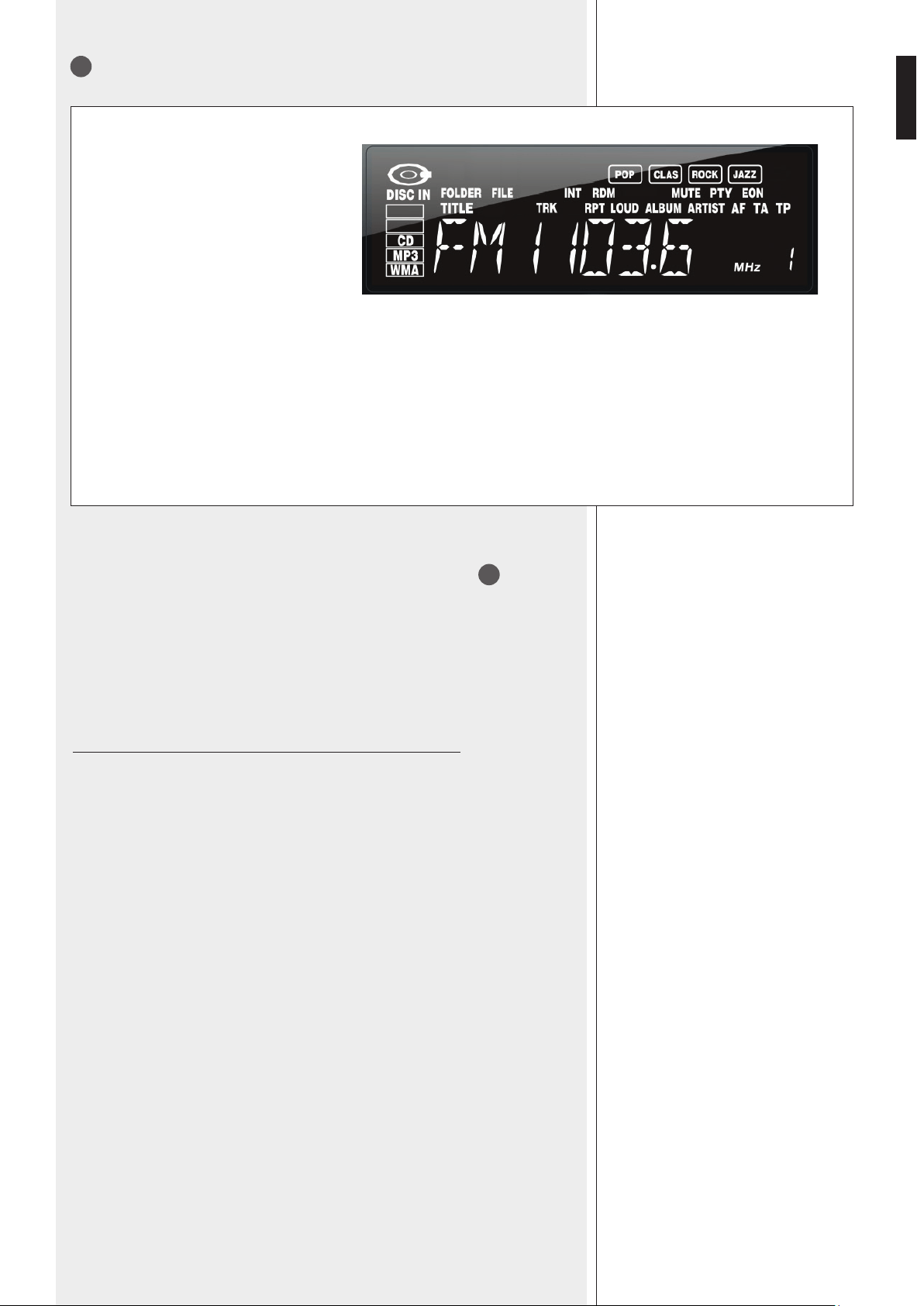
ENGLISH
Tuner main information: selected
group (FM1, FM2, FM3, MW1, MW2),
frequency and if it corresponds to a
stored preset (indicated in the bottom
right hand corner).
POP – CLAS – ROCK – JAZZ: DSP
current selection (music equalisation).
INT: track intro function enabled
RDM: random playback
MUTE: player / tuner is muted
PTY: programme type function
EON: enhanced other networks
DISC IN: a compact disc has been
inserted.
CD: audio CD
MP3: MP3 le
WMA: WMA le
FOLDER: current folder
FILE: current le
TITLE: current title
TRK: current track
RPT: repeat function
LOUD: loudness enabled
ALBUM: current album
ARTIST: current artist
AF: alternative frequency search
enabled
TA: trafc announcement function
enabled
TP: station providing trafc information
Push and hold (for 2 seconds) the encoder button (volume control)
4
to enter the
‘function menu’ (wait for a few seconds without pushing it to exit automatically). Every
following button pressure changes the parameter that can be edited:
TA ALARM / SEEK *→ AF *→ TA *→ REG *→ TA VOL *→ RETUNE *→ DSP → LOUD
→ DX / LOCAL → ROLL →V-LAST / ADJ → [A-VOL]
* available only if the tuner is set to FM.
Then turn the encoder to change the value of the selected parameter.
TA ALARM / SEEK
When trying to enable the TA (trafc announcements) function when tuned to a FM radio
station that does not provide this service, the options are:
- ALARM: to display NO TA/TP only (service not available).
- SEEK: to search automatically a radio station providing trafc announcement information.
AF (ALTERNATE FREQUENCY)
If set to ON, the ‘alternative frequency’ function is enabled, allowing the automatic search
of an alternative FM station having a similar programme to the one selected when the
signal reception degrades. If set to OFF, the ‘alternative frequency’ function is disabled.
TA (TRAVEL / TRAFFIC ANNOUNCEMETS)
If set to ON, the trafc information reception mode is enabled. When tuned to a FM radio
station that does not provide trafc information, according to the setting of the previous
TA ALARM / SEEK parameter, it will start the automatic search of a station providing trafc
information (TA SEEK is displayed) or it will be just displayed that this service is not currently
available (NO TA/TP). If set to OFF, the trafc information reception mode is disabled.
REG (REGIONAL LINKS)
If set to ON, the AF function will implement the regional code and only FM radio stations
in the current region can be tuned automatically.
If set to OFF, the AF function will ignore the regional code and all FM radio stations in other
regions can also be tuned automatically.
22
LCD
FUNCTION MENU
FUNCTION MENU

28
ENGLISH
TA VOL: trafc announcement preset forced volume (values: 12 ÷ 45).
RETUNE: interval time from an automatic search of a radio station providing trafc
announcement information (TA SEEK) to the next one.
If set to S: TA SEEK retune interval time is 45 seconds.
If set to L: TA SEEK retune interval time is 3 minutes.
DSP: music preset equalisation
OFF (no equalisation) → POP → ROCK → CLASSIC → JAZZ
LOUD (LOUDNESS): ON / OFF
“Loudness” is a simple way to improve music listening at a low volume level, bass and
treble tones are both boosted to compensate for the poor sensitivity of the human ear at
audible frequency range extremities.
DX / LOCAL
If set to DX: all radio stations can be selected.
If set to LOCAL: only radio station with strong signal can be selected.
ROLL
If set to ON, all information about the current track / le is automatically and sequentially
displayed.
V-LAST / ADJ
CD/USB – MP3/WMA player and tuner initial volume option (when turning on):
- LAST: the same volume level set before turning the device off.
- ADJ: a preset volume level dened by the following parameter A-VOL.
A-VOL (this parameter is available only if the previous V-LAST / ADJ is set to ADJ): volume
level (0 ÷ 47) of the player / tuner when turning it on.
- MP3 (MPEG Audio Layer 3) and WMA (Windows Media Audio) refers to audio
compression types.
- This player reads MP3 / WMA les on CD-ROM, CD-R or CD-RW discs, USB ash drives
and receives data from BLUETOOTH devices; if available, track titles, artists and albums
are displayed (up to 16 characters are displayed, ID3 TAG version 2.0 is required).
- CD-R – CD-RW discs formatted as ‘packet write’ mode are not supported.
- CD-R discs need to be nalized.
- The le extension must be either .mp3 or .wma.
- The max. directory (/ folder) level is 8, including the ‘root’.
- Max. 256 les (including folders) per source.
- If a CD includes both audio tracks and MP3 / WMA les, only the audio tracks will be
played.
- Make sure that when burning a CD-R including MP3 / WMA les, this is formatted as
a ‘data disc’ and NOT as an ‘audio disc’. It is advisable not to write non-MP3 / WMA
les (or unneeded folders) on the CD-R, otherwise its playback may take a long time
to starts.
- With some types of CD-R / CD-RW, data may not be properly written (depending on
their manufacturing quality). High quality discs are recommended.
- When playing an MP3 le with variable bit rate (‘VBR’), the displayed time might not be
correct (and also the INT function may not work properly).
- It is advisable to use MP3 les having a sampling frequency of 44.1 kHz and a xed
bit-rate of at least 128 kbps (if higher, for instance 192 kbps, the sound quality will be
better).
- The player may not play tracks in the order as written on the disc / USB ash drive.
NOTES ABOUT MP3 /
WMA FILES
NOTES ABOUT MP3 / WMA FILES
29
ENGLISH
AMS
AMS
AMS
TRK SCH
FILE SCH
TRK 000 ÷ 090TRK 000 ÷ 009 TRK 000 ÷ 200
FILE
FOLDER
AMS
PUSH THE
‘AMS’ BUTTON
PUSH THE
VOLUME CONTROL
TURN THE
VOLUME
CONTROL
TRACK
SELECTION (no.)
FILE SELECTION
MP3 / WMA FILE SEARCH
MP3 / WMA FILE SEARCH
BLUETOOTH DEVICES
BLUETOOTH DEVICES
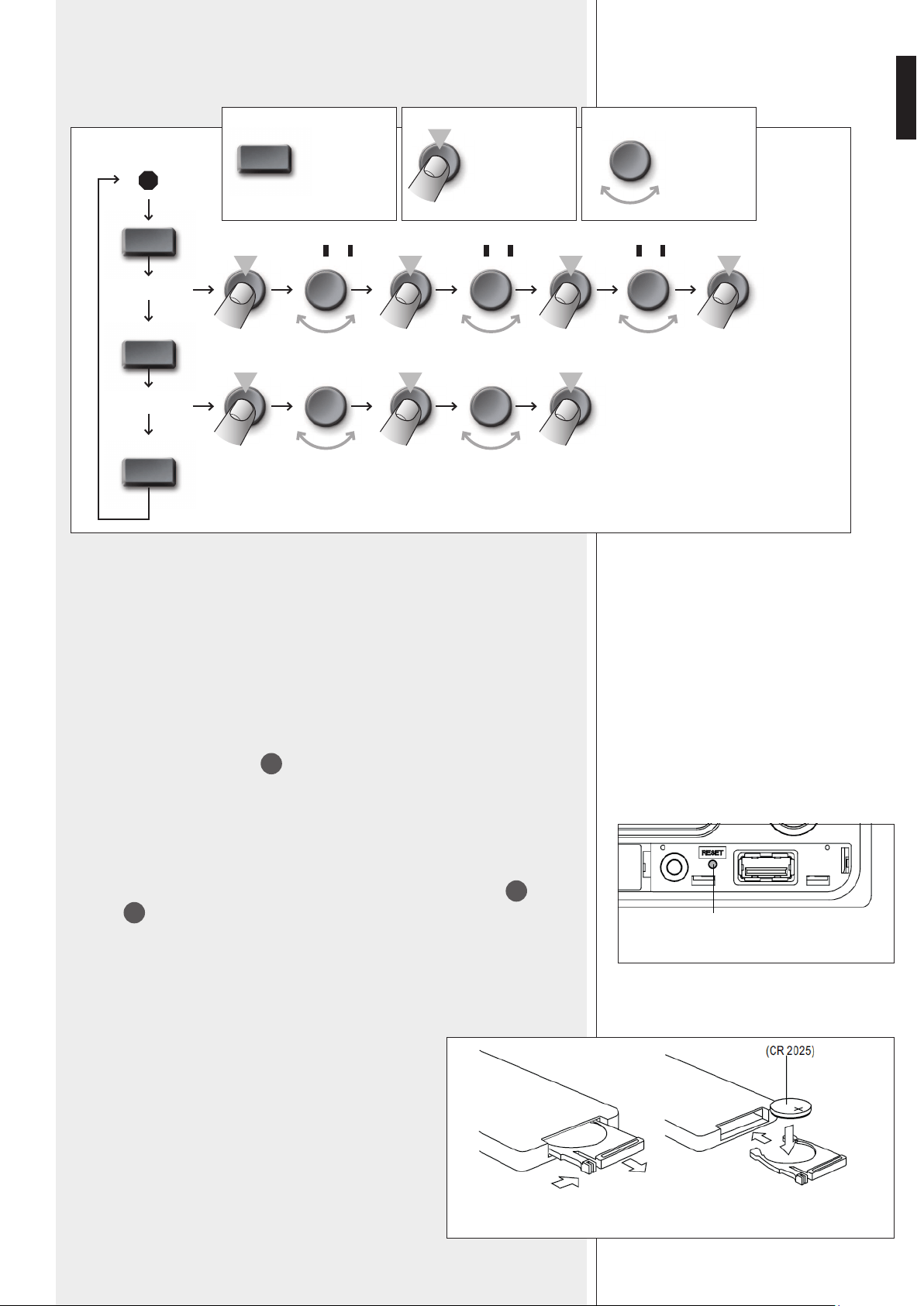
RESET BUTTON
REMOTE CONTROL
REMOTE CONTROL
Bluetooth is a wireless technology standard for exchanging data over short distances
from xed and mobile devices (e.g. cellular phones).
To connect your device to the player:
1. Activate Bluetooth on your device.
2. On your device, search for Bluetooth devices, then ‘RCF’ should be displayed.
3. Match your device to ‘RCF’ by inserting the code (/ password) ‘1234’.
4. Start the playback of an audio le on your device, which now should be included in the
player source list (use the SRC
2
button to change sources).
Push the RESET button (using a small pin only) only in case the player / tuner does not
work properly or for initializing. The RESET button is between the AUX input
17
and the
USB port
18
.
The remote control uses a CR 2025 (3 V) button-type lithium
battery. The battery may need replacing when the remote
control does not operate correctly or for example, it is
necessary to get closer to the player to restore operation. Make
sure the battery polarity replacement is correct.
To insert / replace the battery:
1. Pull out the battery holder while pressing its stopper.
2. Insert the button-type lithium battery with the + mark
facing upward.
3. Insert the battery holder into the remote control.
RESET
1. 2.
3.

30
ENGLISH
ERROR CODES
ERROR CODES
When using the remote control, hold it in the proper way and point it at the player.
ON-OFF It turns on / off the player / tuner (only).
SEL Same function of the volume control
4
when pushed.
VOL ▲(+)▼(–) Same function of the volume control
4
when turned.
│◄◄ (back) Same function of the respective front panel button
5
.
►►│ (forward) Same function of the respective front panel button
6
.
SRC Same function of the SRC button
2
.
AMS Same function of the AMS button
14
.
TA Same function of the TA/AF button
16
, but only for TA on/off.
AF / REG (see below *)
PTY Same function of the PTY button
15
.
BAND Same function of the FM/AM button
3
.
►║ TOP (1) Same function of the ►║ TOP button
7
.
INT (2) Same function of the INT button
8
.
RPT (3) Same function of the RPT button
9
.
RDM (4) Same function of the RDM button
10
.
The
1 ÷ 6 keys can also be used to select / store 6 radio stations (see
20
).
DISP Same function of the DISP button
13
.
* AF / REG (alternative frequency / region; FM tuner, stations with RDS only).
Push and immediately release to enable / disable the ‘alternative frequency’ function (AF
is displayed).
This function (when enabled) allows the automatic search of an alternative station having
a similar programme to the one selected when the signal reception degrades.
Push and hold to switch on / off the ‘region’ option (related to the ‘alternative frequency’
function):
- REG ON (the selected station can only be replaced by another of the same region).
- REG OFF (the selected station can be replaced by any other).
ERROR 1 and 2
Push and hold the EJECT button
19
to eject the compact disc.
If the CD is not ejected, push the RESET button by (using a pin) and then
the EJECT button (hold for 2 seconds) again. Should not be possible to eject
the CD, please consult your dealer (or an authorized service centre).
ERROR 3
The compact-disc has been wrongly inserted upside down.
ERROR 4
The compact disc format is not supported (or data / les are not correct).
SEL
VOL
SRC
AMS
SEARCH
BANDPTYAF/REGTA
4321
DISP65
TOP
INT RPT RDM
MENU
31
ENGLISH
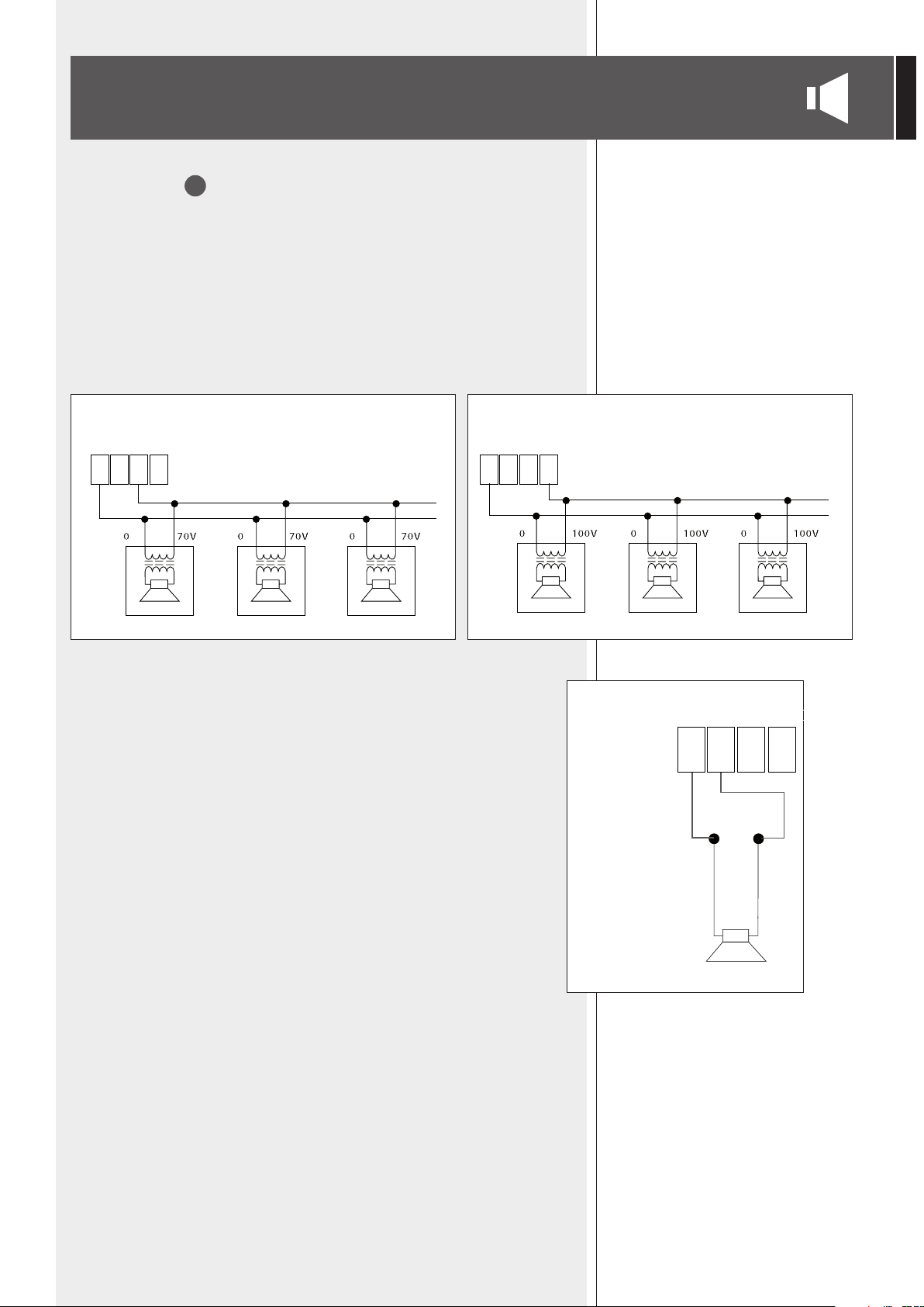
LOUDSPEAKER CONNECTION
DIRECT OUTPUTS
34
Use 1 output only - DO NOT MIX 100 / 70 V CONNECTIONS
70 / 100 V CONSTANT VOLTAGE OUTPUTS
- Each loudspeaker shall have a line transformer with the input voltage equal to the line
voltage (70 / 100 V).
- The loudspeaker total power (considering both direct and zone outputs) shall not be
higher than the amplier maximum power (320 W).
2 W MONITOR OUTPUT FOR A LOW IMPEDANCE LOUDSPEAKER (4 Ω)
The loudspeaker impedance shall not be lower than 4 Ω.
NOTE: AN IMPEDANCE EQUAL TO 4 Ω ALLOWS TO GET THE MAX. POWER (2 W). A HIGHER IMPEDANCE LEADS
TO A REDUCTION OF THE DELIVERED POWER (E.G. 8 Ω: CA. 1 W; 16 Ω: CA. 0.5 W). AN IMPEDANCE LOWER
THAN 4 Ω OVERLOADS THE OUTPUT.
100 V CONSTANT VOLTAGE LINE
70 V CONSTANT VOLTAGE LINE
0 4 Ω 70V 100V0 4 Ω 70V 100V
– +
0 4 Ω 70V 100V
2 W

32
ENGLISH
ZONE OUTPUTS
33
Each zone has a separate 100 V / 70 V constant voltage output.
The factory setting (common for all the 3 zones) is 100 V.
Contact an authorised service centre to select 70 V.
- Each loudspeaker shall have a line transformer with the input voltage equal to the line
voltage (70 / 100 V).
- The loudspeaker total power (considering both direct and zone outputs) shall not be higher
than the amplier maximum power (320 W).
IMPORTANT: THIS MANUAL SECTION CONCERNS QUALIFIED PERSONNEL ONLY.
THE FOLLOWING INSTRUCTION IS TO BE IGNORED BY THE USER.
Inside the amplier, a board having the J3 connector ‘ZONE SELECTOR’ is xed on the
transformer in the centre. The factory setting is 100 V.
Shift the cable terminal a step right (a single pin) to select 70 V.
A
B
C
100 V
J3
70 V
ZONE OUTPUT 100 V / 70 V (COMMON)
VOLTAGE SELECTION

33
ENGLISH
IMPORTANT: THIS MANUAL SECTION CONCERNS QUALIFIED PERSONNEL ONLY.
THE FOLLOWING INSTRUCTIONS ARE TO BE IGNORED BY THE USER.
Make sure the device is not connected to the mains (unplug the power cord).
Remove the lid.
The power supply circuit is under the ventilation screen (see picture 1),
which can be removed by unscrewing the 2 screws.
PICTURE 1
The voltage change connector is
highlighted by a square in the picture 2.
If the mains voltage is 230 V, set the connector to the 230Vac position (see the picture
3), according to the PCB indication (looking at the connector front, the central pin is
connected to the right one).
If the mains voltage is 115 V, set the connector to the 115 Vac position (see the picture
4), according to the PCB indication (looking at the connector front, the central pin is
connected to the left one).
Refit the power supply circuit metallic screen and the device lid.
Before connecting the device to the mains, make sure that the fuse (inside the IEC
power supply connector of the rear panel) is the correct current rating for the mains
voltages (read the fuse indication below the connector).
PICTURE 2
PICTURE 3
PICTURE 4
POWER SUPPLY VOLTAGE CHANGE

34
ITALIANO
SPECIFICATIONS
AMPLIFIER
OUTPUT POWER
DISTORTION (@ 1 KHZ, NOMINAL POWER)
PRESENCE CONTROL (INPUTS 1 ÷ 4)
HIGH-PASS FILTER (INPUTS 1 ÷ 4)
INPUTS 1 ÷ 4, LINE
Input nominal sensitivity
Max. input
Signal / noise ratio
Frequency response (– 3 dB)
Impedance @ 1 kHz
INPUTS 1 ÷ 4, LINE WITH PHANTOM
Input nominal sensitivity
Max. input
Signal / noise ratio
Frequency response (– 3 dB)
Impedance @ 1 kHz
INPUTS 1 ÷ 4, MIC. / MIC. WITH PHANTOM
Input nominal sensitivity
Max. input
Signal / noise ratio
Frequency response (– 3 dB)
Impedance @ 1 kHz
AUX INPUT
Input nominal sensitivity
Input sensitivity range
Max. input
Signal / noise ratio
Frequency response (– 3 dB)
AUX INPUT TONE CONTROLS
- Bass
- Treble
PHANTOM POWER VOLTAGE / CURRENT
PRE OUT NOMINAL OUTPUT LEVEL
PAGING OUT NOMINAL OUTPUT LEVEL
MUSIC OUT NOMINAL OUTPUT LEVEL
MUSIC ON HOLD NOMINAL OUTPUT LEVEL
LOUDSPEAKER OUTPUTS
Low impedance
Constant voltage
320 W (RMS)
< 0.3 %
+ 9.5 dB @ 2.2 kHz
150 Hz
– 7 dBu
+ 21 dBu
80 dB
70 Hz ÷ 11.5 kHz
20 kΩ (balanced) / 10 kΩ (unbalanced)
– 26 dBu
0 dBu
80 dB
70 Hz ÷ 11.5 kHz
6.5 kΩ (balanced)
– 56 dBu
– 28 dBu
65 dB
70 Hz ÷ 11.5 kHz
20 kΩ (balanced) / 10 kΩ (unbalanced)
0 dBu (adjustable)
– 11 ÷ + 10 dBu
+ 14 ÷ 24 dBu
79 dB
40 Hz ÷ 14.5 kHz
± 8 dB @ 80 Hz
± 8 dB @ 13 kHz
32 V / 18 mA
0 dBm (affected by channel volume controls, presence
control, music selectors and controls, not by the front
panel / remote MASTER volume control)
0 dBm (affected by channel volume controls, presence
control, not by the front panel / remote MASTER volume
control)
0 dBm (affected by music selectors and controls, not by
the front panel / remote MASTER volume control)
0 dBm (affected by the AUX INPUT gain only)
4 Ω - power: 2 W
70 V (16 Ω) / 100 V (31 Ω) - power: 320 W

35
ITALIANO
RADIO
FM range
FM frequency response
FM channel separation (1 khz)
FM intermediate rejection
FM image rejection
FM signal / noise ratio
AM (mw) range
Antenna input
AUDIO CD
Frequency response
Signal / noise ratio
Total harmonic distortion (1 kHz)
Channel separation
PROTECTIONS
Amplier
Load
Power supply
GENERIC
Operating voltage
Power (consumption)
Dimensions (w, h, d)
Net weight
87.5 ÷ 108 MHz
30 Hz ÷ 15 kHz
≥ 30 dB
≥ 70 dB
≥ 50 dB
≥ 55 dB
522 ÷ 1620 kHz
75 Ω - Coaxial
20 Hz ÷ 20 kHz
≥ 80 dB
< 0.2 %
≥ 55 dB
Short circuit, thermal
DC Offset Delay, fuse
fuses
115-230V / 50-60 Hz
600 W
444 mm, 127 mm, 345 mm
10.1 kg
36
ENGLISH
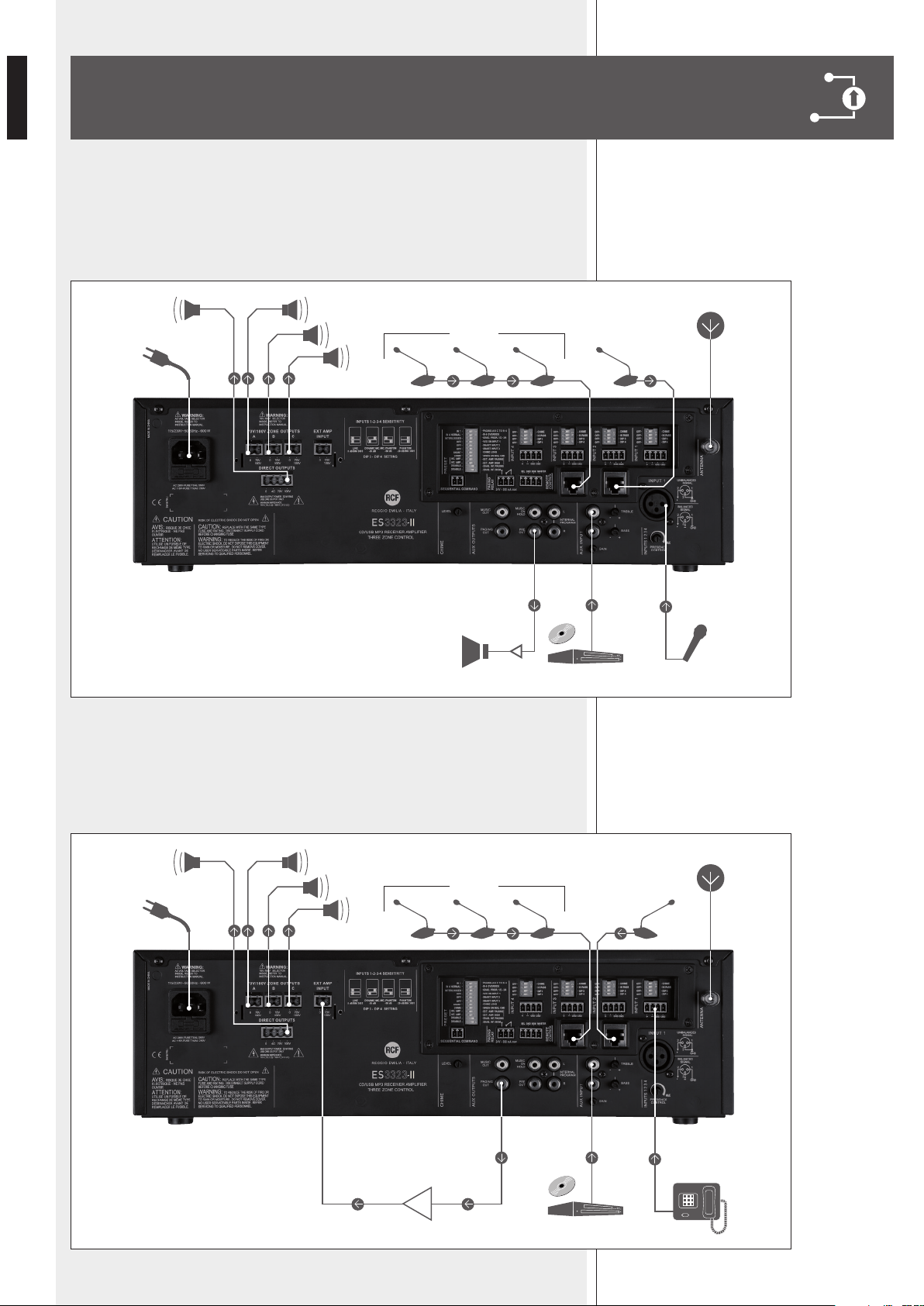
EXAMPLES OF CONNECTIONS
A. 3-zone paging system by using the internal amplier only (the music is not held in
non-paged zones).
An emergency microphone (with highest priority) is connected to the input 1, a BM
3001 paging microphone to the input 2 and a line made of BM 3003 to the input 3.
B. 3-zone paging system in dual amplication ‘A’ mode (the external amplier is
dedicated for paging only).
The music is amplied by the internal amplier and is held in non-paged zones.
A phone system is connected to the input 1 and two lines made of BM 3003 paging
microphones to the inputs 2 and 3.
BM 3001
A
B
C
70 - 100 V70 - 100 V
BM 3003
DVD
A
B
C
70 - 100 V70 - 100 V
BM 3003
BM 3001
DVD
37
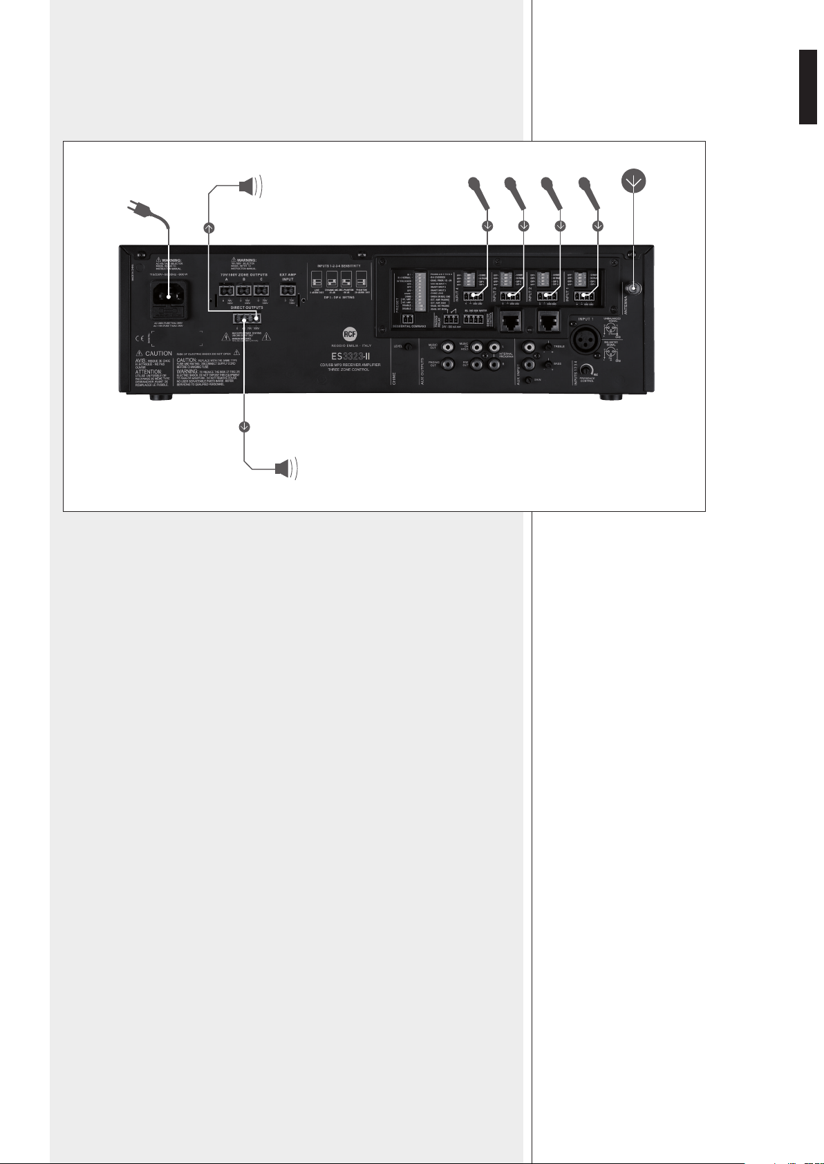
ENGLISH
C. Mix of 4 microphones (with separated volume controls). Only the DIRECT OUT (70 -
100 V) is connected to loudspeakers.
The 4 Ω output (max. 2 W) allows the connection of a monitor loudspeaker.
4 ohm monitor (2 W)
70 - 100 V

38
ITALIANO
IMPORTANTE
ATTENZIONE
AVVERTENZE PER
LA SICUREZZA
Prima di collegare ed utilizzare questo prodotto, leggere attentamente le istruzioni
contenute in questo manuale, il quale è da conservare per riferimenti futuri. Il presente
manuale costituisce parte integrante del prodotto e deve accompagnare quest’ultimo
anche nei passaggi di proprietà, per permettere al nuovo proprietario di conoscere le
modalità d’installazione e d’utilizzo e le avvertenze per la sicurezza.
L’installazione e l’utilizzo errati del prodotto esimono la RCF S.p.A. da ogni responsabilità.
ATTENZIONE: Per prevenire i rischi di amme o scosse elettriche, non esporre mai questo
prodotto alla pioggia o all’umidità.
AVVERTENZE PER LA SICUREZZA
1. Tutte le avvertenze, in particolare quelle relative alla sicurezza, devono essere lette con
particolare attenzione, in quanto contengono importanti informazioni.
2. ALIMENTAZIONE DIRETTA DA RETE
- La tensione di alimentazione dell’apparecchio ha un valore sufcientemente alto da
costituire un rischio di folgorazione per le persone: non procedere mai all’installazione
o connessione dell’apparecchio con l’alimentazione inserita.
- Prima di alimentare questo prodotto, assicurarsi che tutte le connessioni siano corrette
e che la tensione della vostra rete di alimentazione corrisponda quella di targa
dell’apparecchio, in caso contrario rivolgetevi ad un rivenditore RCF.
- Le parti metalliche dell’apparecchio sono collegate a terra tramite il cavo di alimentazione.
Un apparecchio avente costruzione di CLASSE I deve essere connesso alla presa di rete
con un collegamento alla terra di protezione.
- Accertarsi che il cavo di alimentazione dell’apparecchio non possa essere calpestato o
schiacciato da oggetti, al ne di salvaguardarne la perfetta integrità.
- Per evitare il rischio di shock elettrici, non aprire mai l’apparecchio: all’interno non vi
sono parti che possono essere utilizzate dall’utente.
3. Impedire che oggetti o liquidi entrino all’interno del prodotto, perché potrebbero causare
un corto circuito. L’apparecchio non deve essere esposto a stillicidio o a spruzzi d’acqua;
nessun oggetto pieno di liquido (es. vasi), né sorgente di amma nuda (es. candele accese),
deve essere posto sull’apparecchio.
4. Non eseguire sul prodotto interventi / modiche / riparazioni se non quelle espressamente
descritte sul manuale istruzioni.
Contattare centri di assistenza autorizzati o personale altamente qualicato quando:
- l’apparecchio non funziona (o funziona in modo anomalo);
- il cavo di alimentazione ha subito gravi danni;
- oggetti o liquidi sono entrati nell’apparecchio;
- l’apparecchio ha subito forti urti.
5. Qualora questo prodotto non sia utilizzato per lunghi periodi, scollegare il cavo
d’alimentazione.
6. Nel caso che dal prodotto provengano odori anomali o fumo, spegnerlo immediatamente
e scollegare il cavo d’alimentazione.
7. I terminali marcati con il simbolo
sono da ritenersi ATTIVI e PERICOLOSI ed il loro
collegamento deve essere effettuato da PERSONE ADDESTRATE oppure si devono utilizzare
cavi già pronti.
8. Non collegare a questo prodotto altri apparecchi e accessori non previsti.

39
ITALIANO
NOTE IMPORTANTI
PRECAUZIONI D’USO
Quando è prevista l’installazione sospesa, utilizzare solamente gli appositi punti di
ancoraggio e non cercare di appendere questo prodotto tramite elementi non idonei o
previsti allo scopo.
Vericare inoltre l’idoneità del supporto (parete, softto, struttura ecc., al quale è ancorato
il prodotto) e dei componenti utilizzati per il ssaggio (tasselli, viti, staffe non fornite da
RCF ecc.) che devono garantire la sicurezza dell’impianto / installazione nel tempo, anche
considerando, ad esempio, vibrazioni meccaniche normalmente generate da un trasduttore.
Per evitare il pericolo di cadute, non sovrapporre fra loro più unità di questo prodotto,
quando questa possibilità non è espressamente contemplata dal manuale istruzioni.
9. La RCF S.p.A. raccomanda vivamente che l’installazione di questo prodotto sia eseguita
solamente da installatori professionali qualicati (oppure da ditte specializzate) in grado di
farla correttamente e certicarla in accordo con le normative vigenti.
Tutto il sistema audio dovrà essere in conformità con le norme e le leggi vigenti in materia
di impianti elettrici.
10. Sostegni e Carrelli
Se previsto, il prodotto va utilizzato solo su carrelli o sostegni consigliati dal produttore.
L’insieme apparecchio-sostegno / carrello va mosso con estrema cura. Arresti improvvisi,
spinte eccessive e superci irregolari o inclinate possono provocare il ribaltamento
dell’assieme.
11. I fattori meccanici ed elettrici sono da considerare quando si installa un sistema audio
professionale (oltre a quelli prettamente acustici, come la pressione sonora, gli angoli di
copertura, la risposta in frequenza, ecc.).
12. Perdita dell’udito
L’esposizione ad elevati livelli sonori può provocare la perdita permanente dell’udito. Il
livello di pressione acustica pericolosa per l’udito varia sensibilmente da persona a persona
e dipende dalla durata dell’esposizione. Per evitare un’esposizione potenzialmente
pericolosa ad elevati livelli di pressione acustica, è necessario che chiunque sia sottoposto
a tali livelli utilizzi delle adeguate protezioni; quando si fa funzionare un trasduttore in
grado di produrre elevati livelli sonori è necessario indossare dei tappi per orecchie o delle
cufe protettive.
Consultare i dati tecnici contenuti nei manuali istruzioni per conoscere le massime pressioni
sonore che i diffusori acustici sono in grado di produrre.
Per evitare fenomeni di rumorosità indotta sui cavi che trasportano segnali dai microfoni o
di linea (per esempio 0dB), usare solo cavi schermati ed evitare di posarli nelle vicinanze di:
- apparecchiature che producono campi elettromagnetici di forte intensità (per esempio
trasformatori di grande di potenza);
- cavi di rete;
- linee che alimentano altoparlanti.
Non ostruire le griglie di ventilazione dell’unità. Collocare il prodotto lontano da fonti di
calore e garantire la circolazione dell’aria in corrispondenza delle griglie di aerazione.
Non sovraccaricare questo prodotto per lunghi periodi.
Non forzare mai gli organi di comando (tasti, manopole ecc.).
Non usare solventi, alcool, benzina o altre sostanze volatili per la pulitura delle parti
esterne dell’unità.
CLASS 1
LASER PRODUCT

40
ITALIANO
RCF S.P.A. VI RINGRAZIA PER L’ACQUISTO DI QUESTO PRODOTTO, REALIZZATO
IN MODO DA GARANTIRNE L’AFFIDABILITÀ E PRESTAZIONI ELEVATE.
DESCRIZIONE
ES 3323 è un mixer-amplicatore avente 4 ingressi audio mic.-linea su connettori
rimovibili (l’ingresso 1 dispone inoltre di connettore XLR), lettore CD/USB – MP3/WMA e
sintonizzatore radio integrati, 2 ingressi ausiliari (uno sul retro con doppio connettore RCA,
uno sul lettore CD/USB – MP3/WMA frontale con connettore jack 1/8”) per riproduttori
musicali esterni.
La potenza nominale dell’amplicatore è 320 W, ripartibile liberamente su 3 uscite separate
100 – 70 V (3 zone di sistema, per diffusori acustici con trasformatore).
Sono inoltre disponibili un’uscita comune diretta (100 – 70 V) ed un’uscita monitor a bassa
impedenza (min. 4 Ω, potenza max.: 2 W).
Come espansione (opzionale) del sistema, è prevista la connessione di un secondo
amplicatore generico (di potenza adeguata al carico dei diffusori, ad esempio RCF UP
2321) per il mantenimento della musica di sottofondo nelle zone non interessate dagli
annunci microfonici; nel funzionamento con doppio amplicatore, è possibile inviare il
segnale musicale all’amplicatore interno (ES 3323) oppure a quello esterno addizionale.
Sul pannello frontale, sono presenti 3 tasti “PAGING” (assegnabili al solo ingresso 1 o 4)
per l’attivazione selettiva delle zone durante un annuncio (piu un tasto per la chiamata
generale).
Nel funzionamento con doppio amplicatore e senza eventi attivi di priorita, questi 3 tasti
attivano la diffusione del segnale miscelato degli ingressi 1, 2, 3, 4 nelle rispettive zone.
Sono inoltre presenti 3 tasti “MUSIC” per l’attivazione della musica (o la miscelazione di
tutti gli ingressi, in assenza di eventi prioritari nel funzionamento a singolo amplicatore)
nelle rispettive zone.
Un circuito di rilevazione del segnale (“VOX”) con funzione di attivazione della priorita è
presente sull’ingresso 1.
Tutti gli ingressi 1, 2, 3 e 4 possono ottenere la priorita tramite un comando esterno
(collegato al connettore rimovibile); gli ingressi 2 e 3 hanno inoltre un connettore RJ
45 per la rapida connessione (tramite cavo CAT5) di una base microfonica dedicata BM
3001 oppure BM 3003 o una catena di BM 3003 (max. 12, utilizzando un alimentatore
supplementare).
Una porta USB sul pannello frontale permette di utilizzare una chiave apposita (una
memoria, “USB ash drive”) per la riproduzione di le MP3 / WMA.
È inoltre possibile abbinare un dispositivo “Bluetooth” (es. un telefono cellulare) al lettore
CD / MP3 / WMA.
Sono presenti delle uscite ausiliarie per inviare il segnale delle sorgenti musicali interne
ed esterne ad amplicatori addizionali oppure ad una centrale telefonica (come musica di
attesa).
I 4 ingressi universali hanno un controllo comune di “presenza” e ltri passa-alto (inseribili
separatamente) utili per migliorare l’intelligibilita della voce; la sorgente musicale interna
(lettore CD/USB – MP3/WMA e sintonizzatore radio) e l’ingresso ausiliario AUX INPUT sul
retro hanno controlli di tono separati.
Sono presenti indicatori luminosi relativi allo stato dell’apparecchio (ON, PROT), all’attivita
del circuito di priorita (PRIOR) ed al livello del segnale audio (SIG/PK).
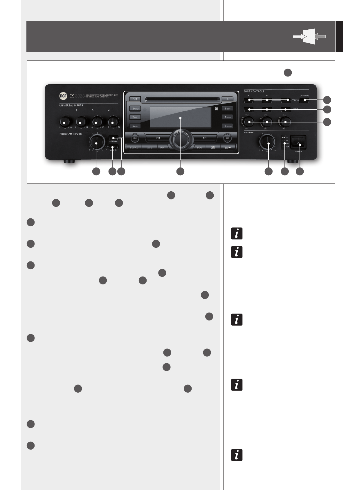
41
ITALIANO
PANNELLO FRONTALE
1
10
9
11
12
8765432
1
Controlli del volume di ciascun ingresso universale 1, 2, 3, 4
NOTA: NEL CASO UNO O PIÙ INGRESSI NON SIANO UTILIZZATI, LASCIARE I RELATIVI CONTROLLI A 0.
2
Controllo di volume dell’ingresso ausiliario AUX INPUT
21
NOTA: LASCIARE IL CONTROLLO A 0 NEL CASO CHE L’INGRESSO AUSILIARIO NON SIA UTILIZZATO.
3
Pulsante AUX IN con indicatore luminoso
Attiva (LED acceso) o disattiva l’ingresso ausiliario AUX INPUT
21
verso l’amplicatore
interno e le uscite audio PRE OUT
23
e MUSIC OUT
26
.
La sua attivazione esclude automaticamente (se presente) il segnale del lettore CD/
USB MP3 – sintonizzatore radio (l’indicatore luminoso del pulsante INTERNAL
4
si
spegne).
IL SEGNALE PRESENTE ALL’INGRESSO AUX INPUT È SEMPRE RIPORTATO SULL’USCITA MUSIC ON HOLD
24
(NON SOGGETTA AL CONTROLLO DEL PULSANTE AUX IN).
4
Pulsante INTERNAL con indicatore luminoso
Attiva (LED acceso) o disattiva il segnale del lettore CD/USB MP3 – sintonizzatore radio
integrato verso l’amplicatore interno e le uscite audio PRE OUT
23
e MUSIC OUT
26
.
La sua attivazione esclude automaticamente (se presente) il segnale dell’ingresso
ausiliario AUX INPUT (l’indicatore luminoso del pulsante AUX IN
3
si spegne).
IL SEGNALE DEL LETTORE CD/USB MP3 – SINTONIZZATORE RADIO È SEMPRE RIPORTATO SULL’USCITA
INTERNAL PROGRAM
22
(NON SOGGETTA AL CONTROLLO DEL PULSANTE INTERNAL
4
).
TRASCORSI 10 SECONDI DOPO AVER PREMUTO UNO DEI 2 PULSANTI (AUX IN OPPURE INTERNAL), L’ULTIMA
SELEZIONE È AUTOMATICAMENTE MEMORIZZATA.
5
Lettore CD/USB – MP3 e sintonizzatore radio (per l’uso, vedere la relativa sezione del
manuale).
6
Controllo di volume principale (MASTER) dell’amplicatore interno.
NOTA: TUTTE LE USCITE SU CONNETTORI RCA (INTERNAL PROGRAM, MUSIC ON HOLD, PRE OUT,
MUSIC OUT, PAGING OUT) NON SONO SOGGETTE A QUESTO CONTROLLO.
IMPORTANTE: dopo aver premuto un tasto tra AUX IN
3
, INTERNAL
4
,
GENERAL
9
, PAGING
10
, MUSIC
11
, occorre attendere circa 10 secondi
afnché le modiche alla congurazione siano attuate.
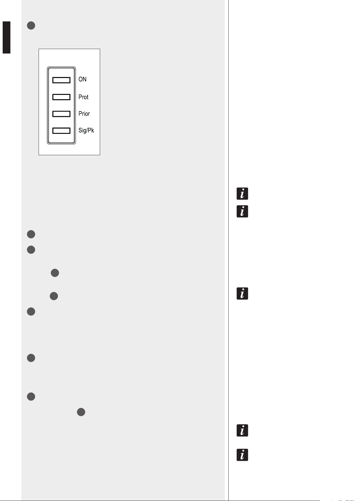
42
ITALIANO
7
Indicatori luminosi (LED)
ON verde: l’apparecchio è acceso
PROT rosso: l’apparecchio è in protezione per
sovraccarico
arancio: l’apparecchio è in protezione per
riscaldamento eccessivo
PRIOR giallo: indica l’inserimento di qualsiasi
priorità (VOX, ingressi univ., SEQ. CMD.).
SIG/PK verde: il livello del segnale audio è
superiore ad almeno –15 dB
verde + rosso: il livello del segnale audio è
compreso tra 0 e +2 dB
rosso: il livello del segnale audio è uguale o
superiore a +3 dB
0 dB = LIVELLO DEL SEGNALE CHE PERMETTE DI OTTENERE LA MASSIMA POTENZA EROGATA DALL’AMPLIFICATORE.
IL CIRCUITO “LIMITER” INTERNO EVITA IL SUPERAMENTO DELLA POTENZA MASSIMA DELL’AMPLIFICATORE, TUTTAVIA
È CONSIGLIABILE ABBASSARE IL VOLUME MASTER (OPPURE IL SINGOLO VOLUME DI UN SEGNALE ECCESSIVO)
QUANDO IL LED SIG/PK È COSTANTEMENTE ROSSO.
8
Interruttore principale dell’apparecchio POWER (0 = spento; I = acceso)
9
Tasto GENERAL
Se attivo, precongura le selezione di tutte le 3 zone per gli annunci, i quali saranno diffusi
al volume massimo possibile (funzione “override”) a prescindere dalle regolazioni degli
attenuatori
12
.
CON IL TERMINE “OVERRIDE” SI INTENDE LA DIFFUSIONE DEL SEGNALE SENZA IL CONTROLLO DI LIVELLO DEGLI
ATTENUATORI
12
.
10
Tasti PAGING (uno per ciascuna zona)
Se attivo, ciascun tasto precongura la selezione (per il solo ingresso 1 o 4) della
rispettiva zona per gli annunci. Nel funzionamento con doppio amplicatore e senza
eventi attivi di priorità, questi 3 tasti attivano la diffusione del segnale miscelato degli
ingressi 1, 2, 3, 4 nelle rispettive zone.
11
Tasti MUSIC (uno per ciascuna zona)
Se attivo, ciascun tasto invia la musica (lettore interno / ingresso ausiliario AUX INPUT)
o la miscelazione di tutti gli ingressi in assenza di eventi prioritari (nel funzionamento a
singolo amplicatore) nella rispettiva zona.
12
Attenuatori (uno per ciascuna zona)
Ciascun attenuatore agisce sulla potenza erogata nella rispettiva uscita separata 70 V /
100 V ZONE OUTPUTS
33
.
I 3 ATTENUATORI NON MODIFICANO LA POTENZA DELL’USCITA AMPLIFICATA COMUNE DIRETTA DIRECT
OUTPUTS, CHE RIMANE SEMPRE AL LIVELLO MASSIMO POSSIBILE.
UN EVENTO PRIORITARIO CON FUNZIONE “OVERRIDE” (ES. UN ANNUNCIO IMPORTANTE CHE DEVE ESSERE INVIATO
AD ALTO VOLUME ANCHE NELLE ZONE DOVE LA POTENZA È RIDOTTA DAGLI ATTENUATORI) È SEMPRE DIFFUSO CON IL
VOLUME MASSIMO POSSIBILE, A PRESCINDERE DALL’IMPOSTAZIONE DEGLI ATTENUATORI.
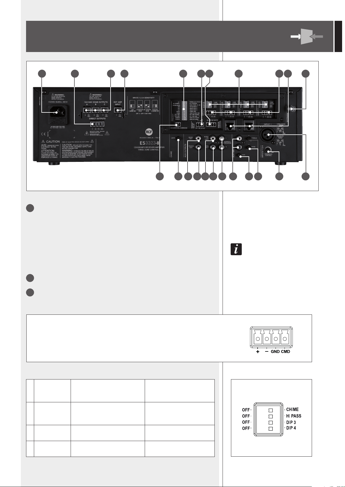
43
ITALIANO
13
2 ingressi relativi ai canali 2 e 3 con prese RJ 45. A ciascun ingresso si può collegare:
una sola base microfonica dedicata BM 3001
oppure una sola base microfonica BM 3003 (3 zone)
oppure una catena di max. 12 BM 3003, utilizzando un alimentatore supplementare.
NOTA RIGUARDO L’IMPOSTAZIONE DEI MICROINTERRUTTORI (“DIP-SWITCH”) 3 E 4 (VEDERE IL PUNTO 16): NEL
CASO SIA COLLEGATA UNA BASE MICROFONICA BM 3001, È NECESSARIO IMPOSTARE LA MODALITÀ “LINEA CON
PHANTOM” (DIP 3 E 4 SU ON); NEL CASO SIANO COLLEGATE UNA O PIÙ BASI MICROFONICHE BM 3003, È
NECESSARIO IMPOSTARE LA MODALITÀ “LINEA” (DIP 3 E 4 SU OFF).
14
Presa per antenna (necessaria al funzionamento del sintonizzatore radio).
15
4 ingressi audio bilanciati con prese per connettori rimovibili relativi ai
canali 1, 2, 3, 4.
+ Ingresso audio positivo
– Ingresso audio negativo
GND massa
CMD comando per ottenere la priorità quando connesso a massa (GND)
1 OFF – CHIME
OFF: la melodia di preavviso
“chime” è disattivata.
CHIME: (ON) la melodia di
preavviso “chime” si attiva
durante un evento di priorità.
2 OFF – HI PASS
OFF: il ltro passa-alto
dell’ingresso audio è disinserito
(risposta in frequenza lineare).
HI PASS: (ON) il ltro passa-
alto dell’ingresso audio è
inserito.
3 OFF – DIP 3 OFF: vedere la tabella successiva.
DIP 3: (ON) vedere la tabella
successiva.
4 OFF – DIP 4 OFF: vedere la tabella successiva.
DIP 4: (ON) vedere la tabella
successiva.
r Ciascun canale dispone di 4 microinterruttori “dip-switch”:
PANNELLO POSTERIORE
35 34 33 32 27 30 31 16 15 13 14
171819202122232425262829
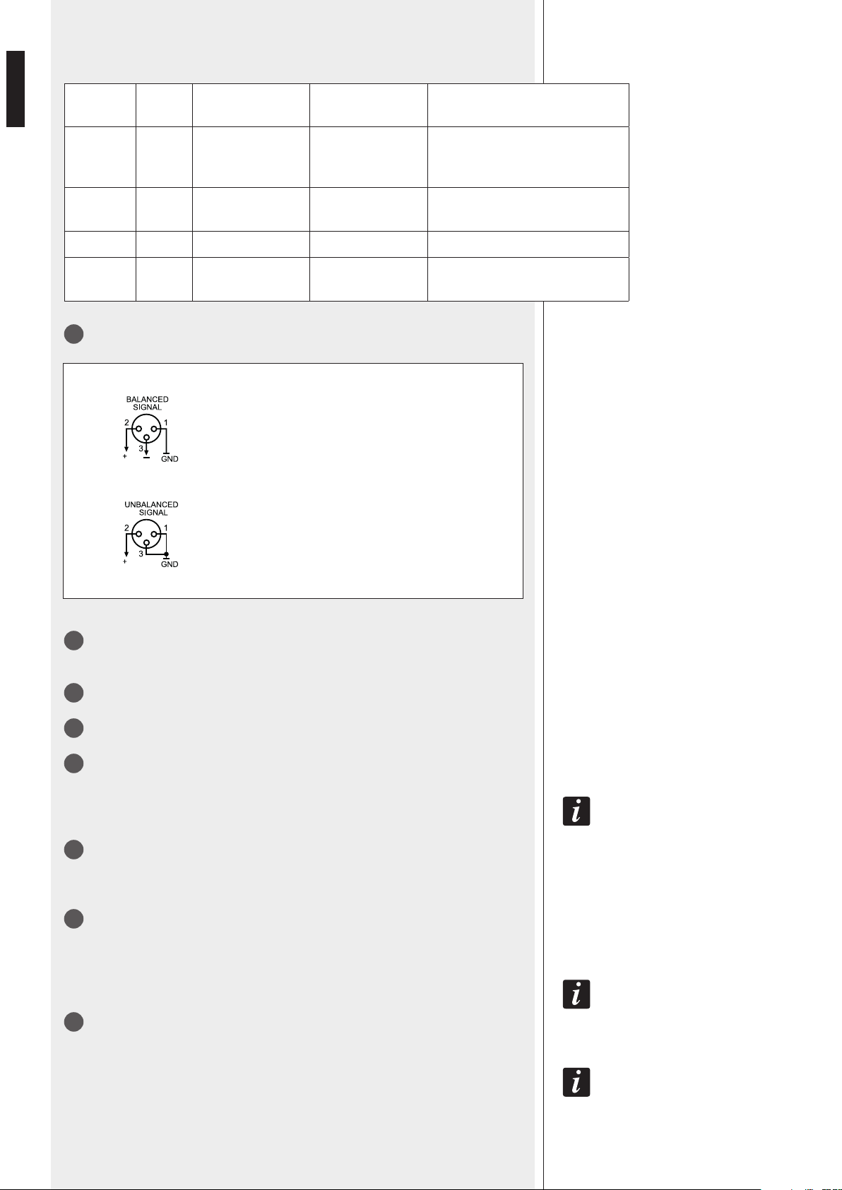
44
ITALIANO
Impostazione dei microinterruttori 3 e 4:
DIP 3 DIP 4 MODO
SENSIBILITA’
D’INGRESSO
ESEMPI DI POSSIBILI
COLLEGAMENTI
OFF OFF LINEA 0 dBu
Base microfonica BM 3003, lettore
CD/MP3, radio, riproduttore di
messaggi, centrale telefonica
ON ON
LINEA con
PHANTOM
– 20 dBu Base microfonica BM 3001
ON OFF MIC. – 50 dBu Microfono dinamico
OFF ON
MIC. con
PHANTOM
– 50 dBu Microfono ad elettrete
17
Ingresso audio canale 1 con connettore XLR:
18
Controllo di “presenza” (toni medi, f = 2,15 kHz) PRESENCE CONTROL comune per
gli ingressi 1 ÷ 4.
19
Controlli di tono TREBLE (alti) e BASS (bassi) dell’ingresso ausiliario AUX INPUT.
20
Controllo di guadagno GAIN dell’ingresso ausiliario AUX INPUT.
21
Ingresso audio ausiliario AUX INPUT con doppio connettore RCA.
I DUE CANALI DEL SEGNALE STEREO PRESENTE ALL’INGRESSO AUX INPUT SONO SOMMATI IN MONO ALL’INTERNO
DELL’APPARECCHIO.
22
Uscita audio stereo con doppio connettore RCA (L: canale sinistro; R: canale
destro) INTERNAL PROGRAM riportante il segnale diretto del lettore CD/USB – MP3 e
sintonizzatore radio.
23
Uscita audio (con connettore RCA) PRE OUT, riportante lo stesso segnale inviato
all’amplicatore di potenza interno (segnale che può essere un evento prioritario oppure
la miscelazione dei canali 1, 2, 3, 4 e della sorgente musicale selezionata).
L’USCITA PRE OUT È UTILE AL FINE DI COLLEGARE UNA O PIÙ UNITÀ DI POTENZA ESTERNE ADDIZIONALI.
24
Uscita audio (con connettore RCA) MUSIC ON HOLD, riportante lo stesso segnale
(ma in mono) presente all’ingresso ausiliario AUX INPUT.
L’USCITA MUSIC ON HOLD (SE È COLLEGATA UNA SORGENTE MUSICALE ESTERNA ALL’INGRESSO AUX
INPUT) E/O L’USCITA INTERNAL PROGRAM POSSONO ESSERE USATE PER IL COLLEGAMENTO AD UNA
CENTRALE TELEFONICA IN MODO DA OTTENERE LA “MUSICA D’ATTESA”.
COLLEGAMENTO BILANCIATO
+ polo positivo
– polo negativo
GND massa
COLLEGAMENTO SBILANCIATO
45
ITALIANO
25
Uscita audio (con connettore RCA) PAGING OUT
All’uscita PAGING OUT, è presente la miscelazione dei canali 1,2,3,4 (senza eventi
di priorità in corso) o il singolo ingresso (1 ÷ 4) attivato da priorità o la melodia di
preavviso “CHIME” (attivata da qualunque priorità, se abilitata) o il suono impostato per
il comando SEQUENTIAL COMMAND
29
.
L’uscita è utilizzabile per il collegamento dell’amplicatore supplementare (se destinato
all’amplicazione degli annunci microfoni e/o alla diffusione degli ingressi 1÷4).
Il controllo principale MASTER
6
e quello remoto (REMOTE CONTROL MASTER
31
)
del volume non hanno effetto su questa uscita.
IL LIVELLO DEL SEGNALE DEGLI INGRESSI 1 ÷ 4 DIPENDE DAL RELATIVO VOLUME DI CANALE
1
, QUELLO DELLA
MELODIA DI PREAVVISO “CHIME” DAL CONTROLLO CHIME LEVEL
28
POSTO SUL RETRO; IL LIVELLO DELLA
SIRENA È FISSO.
26
Uscita audio (con connettore RCA) MUSIC OUT
All’uscita MUSIC OUT, è presente il segnale della sorgente musicale selezionata (lettore
CD/USB – MP3 e sintonizzatore radio interno, ingresso AUX INPUT
21
, nessuna).
Il livello dipende sia dalla regolazione del volume del lettore interno (o dal volume
AUX
2
ed il relativo GAIN
20
sul pannello posteriore per l’ingresso AUX INPUT) sia
dall’eventuale potenziometro per il controllo remoto (morsetto: REMOTE CONTROL BGM
31
).
L’uscita è utilizzabile per il collegamento dell’amplicatore supplementare (se destinato
all’amplicazione della musica).
27
12 microinterruttori “dip-switch” PRESET per le impostazioni di sistema:
1.
IN 1 –
PAGING A B C TO IN 4
IN 1: assegna i 3 tasti di selezione
zone “PAGING” (del pannello frontale)
al canale 1.
PAGING A B C TO IN 4: assegna i 3
tasti di selezione zone “PAGING”
(del pannello frontale) al canale 4.
2.
IN 4 NORMAL –
IN 4 OVERRIDE
IN 4 NORMAL: il canale 4 (se
prioritario) è diffuso con volume
soggetto agli attenuatori }.
IN 4 OVERRIDE: il canale 4 (se
prioritario) è diffuso con volume non
soggetto agli attenuatori }.
3.
INTERLOCKED –
GRAD. PRIOR. 1/2-3/4
INTERLOCKED: impostazione del
modo di priorità interbloccata.
GRADUATED PRIORITY 1/2–3/4:
impostazione del modo di priorità
scalare.
4.
OFF –
VOX ON INPUT 1
OFF: disattivazione della funzione
“VOX”del canale 1.
VOX ON INPUT 1: attivazione
della funzione “VOX” del canale
1 (attivazione automatica della
priorità quando è rilevato un
segnale all’ingresso audio INPUT 1).
5.
OFF –
SMART INPUT 2
OFF: la priorità del canale 2 rimane
attiva solo quando il relativo comando
è presente.
Nota: impostare su OFF se
all’ingresso 2 sono collegate 1 o
più basi microfoniche BM 3003.
SMART INPUT 2: la priorità del
canale 2 è controllata da un
interruttore elettronico interno
bi-stabile (on / off) che commuta ad
ogni comando ad impulso.
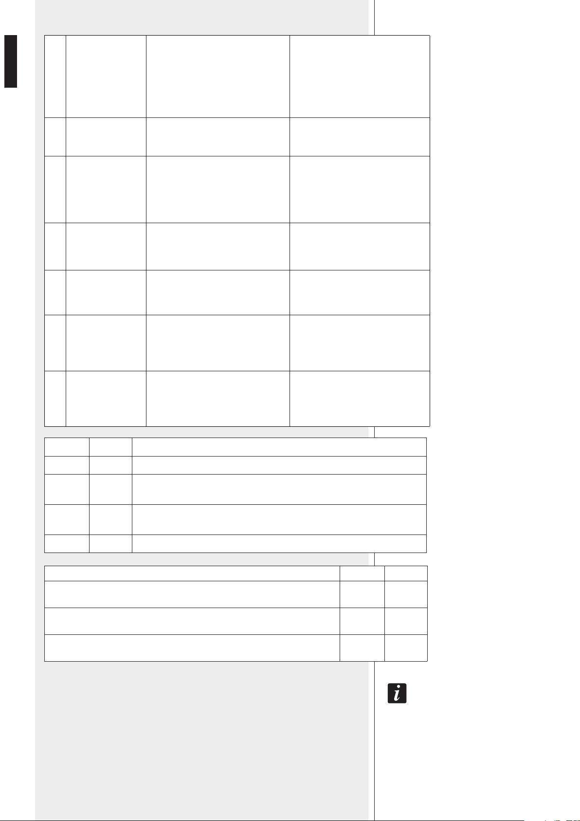
46
ITALIANO
6.
OFF –
SMART INPUT 3
OFF: La priorità del canale 3 rimane
attiva solo quando il relativo
comando è presente.
Nota: impostare su OFF se
all’ingresso 3 sono collegate 1 o
più basi microfoniche BM 3003.
SMART INPUT 3: la priorità del
canale 3 è controllata da un
interruttore elettronico interno
bi-stabile (on / off) che commuta ad
ogni comando ad impulso.
7.
SHORT –
CHIME LONG
SHORT: selezione del primo tipo
(corto) della melodia di preavviso
CHIME.
CHIME LONG: selezione del secondo
tipo (lungo) della melodia di
preavviso CHIME.
8.
CHIME –
SIREN ON SEQ.
CMD
CHIME: utilizzo della melodia di
preavviso (“chime”), impostata
tramite il dip-switch nr.7, quando
si attiva il comando “SEQUENTIAL
COMMAND”
SIREN ON SEQ.CMD: utilizzo di
un segnale d’allarme quando si
attiva il comando “SEQUENTIAL
COMMAND”.
9.
INT. AMP. –
EXT. AMP. PAGING
Vedere la tabella successiva (dip 9 e
10) INT. AMP.: dip-switch 9 OFF
Vedere la tabella successiva (dip 9
e 10) EXT. AMP. PAGING: dip-switch
9 ON
10.
INT. AMP. –
EXT. AMP. BGM
Vedere la tabella successiva (dip 9 e
10) INT. AMP.: dip-switch 10 OFF
Vedere la tabella successiva (dip 9
e 10) EXT. AMP. BGM: dip-switch
10 ON
11.
DISABLE –
ENAB. INT. PAGING
DISABLE: (OFF) disabilita il segnale
degli ingressi 1÷4, il CHIME e la
sirena verso l’amplicatore interno.
ENAB. INT. PAGING: (ON) abilita il
segnale degli ingressi 1÷4, il CHIME
e la sirena verso l’amplicatore
interno.
12.
DISABLE –
ENAB. INT. BGM
DISABLE: (OFF) disabilita il segnale
della sorgente musicale selezionata
verso l’amplicatore interno.
ENAB. INT. BGM: (ON) abilita il
segnale della sorgente musicale
selezionata verso l’amplicatore
interno.
DIP 9 DIP 10 MODALITÀ DI FUNZIONAMENTO
OFF OFF ES 3323 funziona come amplicatore unico per annunci e musica.
ON OFF Doppia amplicazione: ES 3323 per la musica, l’amplicatore esterno addizionale
per gli annunci.
OFF ON Doppia amplicazione: ES 3323 per gli annunci, l’amplicatore esterno
addizionale per la musica.
ON ON ES 3323 funziona come amplicatore unico per annunci e musica.
IMPOSTAZIONE DEI DIP-SWITCH 11 E 12 DIP 11 DIP 12
L’amplicatore addizionale esterno non è previsto (ES 3323 funziona come
amplicatore unico).
ON ON
Doppia amplicazione: ES 3323 per la musica, l’amplicatore esterno addizionale
per gli annunci.
OFF ON
Doppia amplicazione: ES 3323 per gli annunci, l’amplicatore esterno addizionale
per la musica.
ON OFF
L’ATTUAZIONE DI QUALSIASI SELEZIONE (EFFETTUATA TRAMITE “DIP-SWITCH”) AVVIENE SOLO ALLA FINE DI UN
EVENTO PRIORITARIO (ES. UN ANNUNCIO) O ALL’ACCENSIONE DELL’APPARECCHIO.
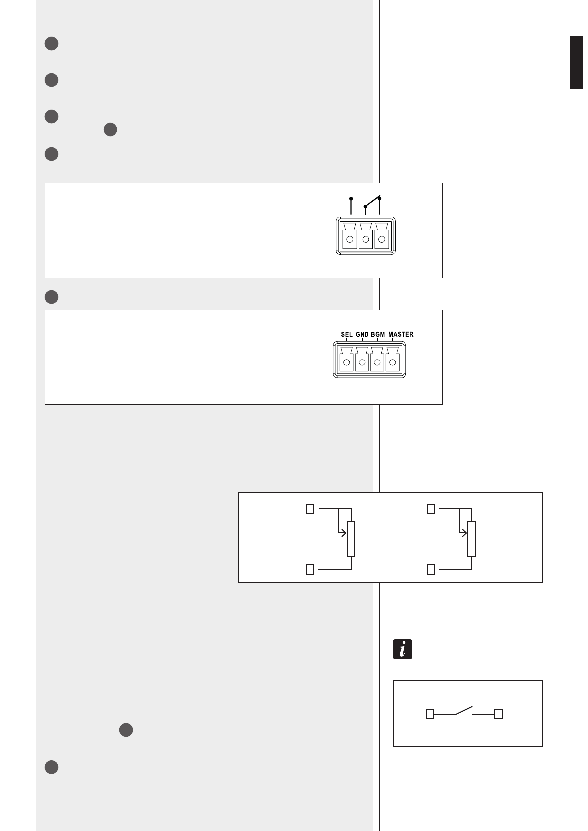
47
ITALIANO
28
Controllo (trimmer regolabile tramite un piccolo cacciavite) CHIME LEVEL del volume
della melodia di preavviso “chime”.
29
Comando SEQUENTIAL COMMAND con connettore rimovibile (attivo quando i due
contatti sono cortocircuitati) per l’invio ripetitivo ed al massimo del volume della melodia
di preavviso “chime” (selezionabile tramite il dip-switch nr.7, vedere la tabella al punto
27
) oppure di un segnale d’allarme (selezionabile tramite il dip-switch nr.8, vedere la
tabella al punto
27
).
30
Contatti di un relè interno PAGING RELAY (tramite connettore rimovibile a 3 poli) per
la segnalazione della funzione di priorità attiva.
31
Terminale con contatti “REMOTE CONTROL” per i controlli remoti
SEL: selezione sorgente musicale (se posto a massa)
GND: massa comune
BGM: volume della musica
MASTER: volume generale
1 2 3
REGOLAZIONE REMOTA DEL VOLUME
La regolazione è indipendente per il volume generale (“MASTER”) e quello della sola
musica (“BGM”) e si ottiene collegando un potenziometro remoto (che funge da reostato)
tra il contatto relativo e la massa “GND”.
Cambiando il valore nominale del potenziometro,
è possibile stabilire il campo di azione desiderato
rispetto all’impostazione principale sul pannello
frontale: più è alto il valore, maggiore risulta il campo
regolato. I valori possono spaziare tipicamente da
10 kΩ a 100 kΩ; l’intervento ottimale lo si ottiene
con un potenziometro a curva logaritmica inversa,
ma è accettabile anche uno con risposta lineare.
La regolazione remota della musica è relativa alla
sorgente attivata (interna o esterna).
L’escursione massima ottenibile è circa 40 dB relativa al segnale preimpostato dalle
regolazioni principali.
SELEZIONE REMOTA DELLA SORGENTE MUSICALE
Si ottiene collegando un pulsante tra i contatti SEL e GND.
La selezione è, a rotazione, tra lettore CD/USB – MP3 e sintonizzatore radio interno,
ingresso AUX INPUT
21
e nessuna sorgente musicale.
SEL GND
IMPORTANTE: SE NON È PREVISTO L’INSERIMENTO DI UN POTENZIOMETRO PER IL CONTROLLO
REMOTO, È NECESSARIO PORRE IN CORTOCIRCUITO IL RELATIVO CONTATTO VERSO MASSA (TRAMITE UN
CONDUTTORE), ALTRIMENTI IL VOLUME GENERALE (MASTER) E/O QUELLO DELLA MUSICA (BGM) SONO
POSTI A ZERO.
MASTER
GND
10 kΩ ÷
100 kΩ
BGM
GND
10 kΩ ÷
100 kΩ
1 – contatto normalmente aperto
2 – contatto comune
3 – contatto normalmente chiuso
Max. tensione applicabile ai contatti: 24 V; portata: 0,5 A.
32
Ingresso EXT AMP INPUT per la linea a tensione costante 100 – 70 V in uscita
dall’amplicatore addizionale.
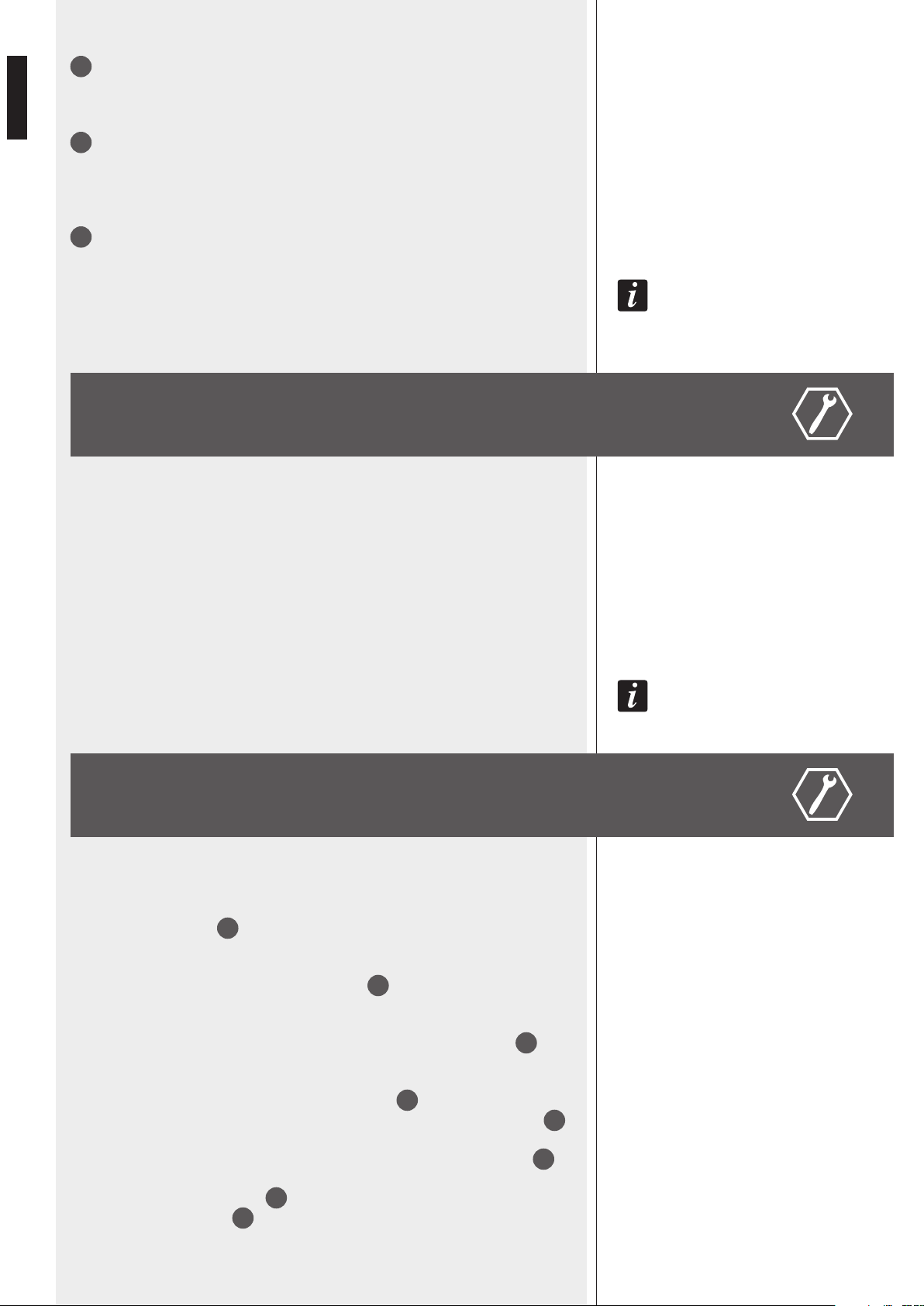
48
ITALIANO
33
Uscite separate ZONE OUTPUTS (una per zona) a tensione costante 100 – 70 V
per il collegamento dei diffusori acustici. Vedere la sezione “Collegamento dei diffusori
acustici”.
34
Uscite dirette DIRECT OUTPUTS (senza selezione zone) di potenza (max. 320 W)
per diffusori con collegamento a tensione costante (100 – 70 V). E’ inoltre presente
un’uscita a bassa impedenza (4 Ω), con potenza max. 2 W, per il collegamento di un
monitor.
35
Connettore con fusibile per l’alimentazione principale da rete.
Prima di effettuare il collegamento, vericare che la tensione di rete corrisponda a quella
impostata (230 V oppure 115 V) nell’apparecchio.
NOTA: IL TIPO DI FUSIBILE DA UTILIZZARSI È SPECIFICATO SUL PANNELLO POSTERIORE (SOTTO IL CONNETTORE).
ES 3323 PUÒ FUNZIONARE IN TRE DIVERSE MODALITÀ:
1. SINGOLA: come unico amplicatore sia per gli annunci, sia per la musica, la quale
non sarà diffusa nelle zone non selezionate durante un evento prioritario in corso;
2. DOPPIA AMPLIFICAZIONE “A”: è previsto il collegamento ad un amplicatore esterno
addizionale (es. RCF UP 2321) dedicato per i soli annunci (mentre quello interno è
utilizzato per la diffusione della sola musica);
3. DOPPIA AMPLIFICAZIONE “B”: è previsto il collegamento ad un amplicatore esterno
addizionale (es. RCF UP 2321) dedicato per la sola musica (mentre quello interno è
utilizzato per la diffusione dei soli annunci).
CON IL TERMINE “VOX”, SI INTENDE UN CIRCUITO INTERNO ALL’APPARECCHIO CHE ATTIVA AUTOMATICAMENTE LA
PRIORITÀ DEL CANALE 1 QUANDO È RILEVATO UN SEGNALE ALL’INGRESSO AUDIO INPUT 1.
FUNZIONAMENTO SENZA EVENTI DI PRIORITÀ ATTIVI
(all’accensione dell’apparecchio oppure al termine di un evento prioritario).
In assenza di qualsiasi comando di priorità attivo (oppure del VOX o del comando
SEQUENTIAL COMMAND
29
), si ha la miscelazione dei canali 1, 2, 3, 4, insieme
all’eventuale sorgente musicale selezionata e memorizzata, la quale può essere:
interna (il lettore CD/USB – MP3 e sintonizzatore radio);
il segnale presente all’ingresso ausiliario AUX INPUT
21
;
nessuna.
Il segnale miscelato è inviato solo alle zone selezionate tramite i 3 tasti MUSIC
11
sul
pannello frontale.
Il volume generale si imposta tramite il controllo MASTER
6
.
Il volume di ciascun ingresso da 1 a 4 è regolato separatamente dai controlli 1, 2, 3, 4
1
.
Il volume della musica dipende dal controllo del lettore CD/USB – MP3 e sintoniz-
zatore radio nel caso sia selezionata tale sorgente, oppure dal controllo di volume
2
dell’ingresso ausiliario AUX IN posto sul pannello frontale dell’apparecchio; il volume
dell’ingresso ausiliario AUX INPUT
21
dipende anche dall’impostazione del relativo
controllo di guadagno GAIN
20
posto sul pannello posteriore.
MODALITÀ DI FUNZIONAMENTO
FUNZIONAMENTO IN MODALITÀ SINGOLA
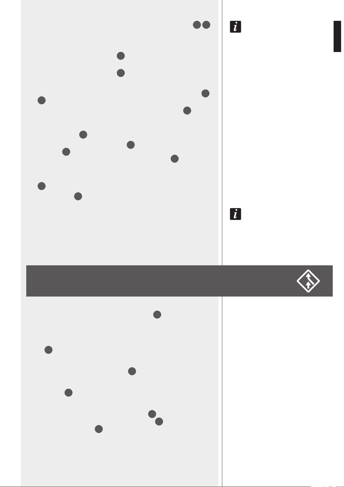
49
ITALIANO
LA SORGENTE MUSICALE (INTERNA O ESTERNA) PUÒ ESSERE ATTIVATA/DISATTIVATA TRAMITE I PULSANTI
3
4
POSTI SUL PANNELLO FRONTALE.
PROCEDERE SECONDO QUEST’ORDINE:
a. assicurarsi che i “dip-switch” PRESET
29
9 e 10 siano entrambi su OFF
(o entrambi su ON);
b. assicurarsi che i “dip-switch” PRESET
29
11 e 12 siano entrambi su ON;
c. impostare (momentaneamente) il volume MASTER [6] circa a metà corsa;
d. selezionare una sorgente musicale (interna o AUX IN) tramite gli appositi tasti
3
4
;
e. selezionare le zone dove diffondere la musica tramite i 3 tasti MUSIC
11
;
f. regolare il volume della musica
(tramite il volume del lettore CD/USB – MP3 e sintonizzatore radio oppure dal
controllo di volume
2
dell’ingresso ausiliario AUX IN);
g. se si utilizzano le uscite separate per zona
33
, mettere temporaneamente gli
attenuatori
12
su MAX.
(non necessario se si utilizza una delle uscite DIRECT OUTPUTS
34
);
h. regolare il VOLUME MASTER per ottenere il livello desiderato;
i. se necessario, attenuare il livello di uscita di ciascuna zona mediante gli attenuatori
12
;
j. regolare i volumi
1
degli ingressi 1 ÷ 4 se utilizzati.
NOTA: SI SUPPONE CHE NON SIANO INSTALLATI I POTENZIOMETRI PER IL CONTROLLO REMOTO DEL VOLUME O, SE
INSTALLATI, SIANO TEMPORANEAMENTE REGOLATI AL MASSIMO.
IL COMANDO DI PRIORITÀ SI OTTIENE:
- per i canali da 1 a 4, collegando (nei connettori rimovibili
15
) il relativo contatto CMD
a massa (GND); la priorità resta attiva se la connessione è stabile (con l’eccezione della
funzione “SMART” degli ingressi 2 e 3);
- per il solo canale 1 tramite funzione VOX (se abilitata);
- mediante le basi microfoniche BM 3003 oppure BM3001 collegate ai connettori
“RJ”
13
dei canali 2 e 3, tenendo presente che, se la linea è impegnata, non può
essere utilizzata la priorità o l’audio sul morsetto rimovibile relativo (onde evitare
malfunzionamenti);
- tramite il comando SEQUENTIAL COMMAND
29
.
In presenza di qualsiasi comando di priorità attivo (oppure del VOX), sulle uscite dirette
DIRECT OUTPUTS
34
per diffusori acustici è disponibile il solo segnale del canale at-
tivato e prioritario (tra gli ingressi 1÷4, le basi microfoniche BM 3003 o BM 3001 ed il
comando SEQUENTIAL COMMAND); la sorgente musicale selezionata e gli altri ingressi
non sono diffusi, nemmeno nelle uscite separate per zona
33
.
Durante l’attivazione del comando di priorità, il LED “PRIOR”
7
si accende ed il segnale
audio inviato all’uscita PRE OUT
23
sarà solo quello del canale prioritario attivo.
PRIORITÀ
50
ITALIANO
DIP 3 MODO
INTERLOCKED INTERBLOCCATO
È accettato solo il comando di
priorità attivato per primo in
uno dei 4 canali (eventualmente
anche la funzione VOX, se
abilitata mediante il dip-switch
4 PRESET
27 ). Nessun altro
comando di priorità sarà accettato
fino a quando non sarà rimosso
quello precedente. Nota: l’unico
evento che può sempre inserirsi
successivamente (ed annullare una
priorità precedente) è il comando
SEQUENTIAL COMMAND 29 .
GRAD. PRIOR.
1/2-3/4
PRIORITA’
SCALARE
Un evento con priorità più alta ha
la precedenza (anche se attivato in
successione).
L’ordine di priorità è:
1. (più alta) comando SEQUENTIAL
CMD.
2. canale 1 (inclusa la funzione VOX)
3. canali 2 e 3 (interbloccati tra loro)
4. canale 4
LA MODALITÀ DI ATTUAZIONE DELLA PRIORITÀ (INCLUSA LA FUNZIONE
VOX) È IMPOSTATA TRAMITE IL DIP-SWITCH 3 DEL GRUPPO PRESET
27
:
Al termine di un evento di priorità, il sistema ripristinerà le condizioni iniziali
(la miscelazione dei canali 1, 2, 3, 4, più l’eventuale sorgente musicale se-
lezionata, a meno che non sia stata attivata nel frattempo una nuova priorità).
Per quanto riguarda la diffusione di annunci selettivi sulle 3 zone A, B, C
(uscite separate ZONE OUTPUTS
33
), si deve considerare:
- lo stato dei pulsanti PAGING
10
, GENERAL
9
sul pannello frontale;
- l’impostazione dei “dip-switch” 1 e 2 del gruppo PRESET
27
sul pannello
posteriore;
- il dispositivo che richiede l’attivazione (ad esempio, tramite base microfonica
BM 3001 si effettuano solo chiamate generali, mentre la BM 3003 permette
la selezione delle zone).
Va tenuta inoltre presente l’impostazione degli attenuatori di zona
12
che regolano la potenza diffusa sulle uscite separate 70 V / 100 V
ZONE OUTPUTS
33
(ma non delle uscite dirette DIRECT OUTPUTS
34
e
dell’amplificatore esterno addizionale eventualmente collegato).
Il segnale audio di un evento prioritario classificato come “override” è sem-
pre diffuso sulle uscite separate al massimo del volume impostato, senza
subire il controllo degli attenuatori; il segnale audio di un evento prioritario
“normale” è controllato anche dagli attenuatori.
CON IL TERMINE “OVERRIDE” SI INTENDE LA DIFFUSIONE DEL SEGNALE SENZA IL CONTROLLO
DI LIVELLO DEGLI ATTENUATORI
12
.

51
ITALIANO
LA DIFFUSIONE DEGLI ANNUNCI SULLE 3 ZONE È SOGGETTA ALLE
SEGUENTI REGOLE:
1. Se il tasto GENERAL
9
è attivo, quando l’attivazione della priorità
avviene da uno dei canali 1 ÷ 4 oppure da una base microfonica BM3001,
la diffusione dell’annuncio è generale (su tutte le 3 zone) in modo
OVERRIDE (a prescindere da qualunque altra impostazione).
2. Durante l’attivazione della priorità dai canali 2 e 3 (oppure da una
base microfonica BM 3001 collegata all’ingresso 2 o 3) o del comando
SEQUENTIAL COMMAND
29
, la diffusione dell’annuncio (o del segnale
d’allarme) è generale (su tutte le 3 zone) in modo OVERRIDE (a
prescindere da qualunque altra impostazione).
3. Le basi microfoniche BM 3003 (collegate agli ingressi 2 e 3) possono
sempre selezionare le zone da attivare (in modo OVERRIDE).
4. Durante l’attivazione della priorità del canale 1, la diffusione avviene
sempre in modalità OVERRIDE; la selezione delle zone dipende dal “dip-
switch” 1 del gruppo PRESET
27
e dai tasti frontali PAGING
10
:
- se il DIP 1 è impostato su “PAGING A B C TO IN 4”, l’annuncio è sempre
generale (a prescindere dalla selezione dei tasti PAGING);
- se il DIP 1 è impostato su “IN 1”, l’annuncio è selettivo verso le zone
selezionate dai tasti PAGING (nota: se non si effettua la selezione di almeno
una zona, l’annuncio è diffuso solo sulle uscite dirette DIRECT OUTPUTS
34
).
5. Durante l’attivazione della priorità del canale 4, la diffusione può avvenire
in modo normale oppure OVERRIDE a seconda dell’impostazione del “dip-
switch” 2 del gruppo PRESET
27
(e del tasto frontale GENERAL
9
); la
selezione delle zone dipende dal “dip-switch” 1 del gruppo PRESET
27
e
dai tasti frontali PAGING
10
:
- se il DIP 1 è impostato su “IN 1”, l’annuncio è sempre generale (a prescindere
dalla selezione dei tasti PAGING);
- se il DIP 1 è impostato su “PAGING A B C TO IN 4”, l’annuncio è selettivo
verso le zone selezionate dai tasti PAGING (nota: se non si effettua la
selezione di almeno una zona, l’annuncio è diffuso solo sulle uscite dirette
DIRECT OUTPUTS
34
).
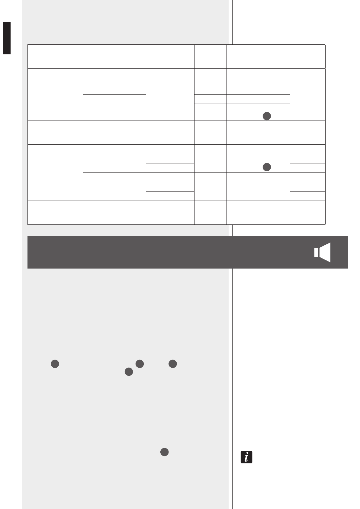
52
ITALIANO
FUNZIONAMENTO CON DOPPIA AMPLIFICAZIONE (“A”)
TABELLA DI CORRELAZIONE TRA COMANDO DI PRIORITÀ ATTIVO E ZONE
ATTIVATE:
COMANDO DI
PRIORITÀ ATTIVO
dip-switch 1
(assegna tasti “paging”)
dip-switch 2
(in.4 “override”)
tasto
“general”
zone attivate
modo
(normale /
“override”)
BASE MIC. BM 3003
zone selezionate sulla
base mic. BM 3003
override
INGRESSO 1
IN 4 tutte
override
IN 1
ON tutte
OFF
zone selezionate tramite i
tasti “paging”
10
INGRESSO 2,
INGRESSO 3,
BASE MIC. BM 3001
tutte override
INGRESSO 4
IN 4
ON tutte
override
ON
OFF
zone selezionate tramite i
tasti “paging”
10
OFF normale
IN 1
ON
tutte
override
ON
OFF
OFF normale
COMANDO
SEQUENTIAL
COMMAND
tutte override
In questa modalità, è previsto il collegamento ad un amplificatore esterno addizionale
(es. RCF UP 2321) dedicato per i soli annunci (mentre quello interno è utilizzato per
la diffusione della sola musica).
ES 3323: MUSICA AMPLIFICATORE ESTERNO: ANNUNCI
Per i collegamenti e le impostazioni necessari: vedere la sezione “Collegamento
dell’amplicatore esterno addizionale”, paragrafo “A”.
IN ASSENZA DI EVENTI CON PRIORITÀ:
- la musica (sorgente sonora interna od esterna) è diffusa in tutte le zone aventi il tasto
MUSIC
11
attivato (o entrambi i tasti MUSIC
11
e PAGING
10
attivati);
- tutte le zone con il solo tasto PAGING
11
attivato diffondono la miscelazione dei
canali da 1 a 4 (tramite l’amplicatore esterno).
Durante un evento con priorità (es. un annuncio), la diffusione del segnale prioritario
nelle 3 zone ha luogo nei modi già descritti nella sezione precedente del manuale
“Funzionamento in modalità singola”, ad eccezione della funzione OVERRIDE (in
quanto il livello del segnale prioritario dipende dalle impostazioni del volume
dell’amplicatore esterno).
La musica rimane presente (se attivata) nelle zone non interessate dall’evento
prioritario.
DURANTE UN EVENTO DI PRIORITÀ, NELLE ZONE CON IL SOLO TASTO PAGING
11
ATTIVATO È INVIATO SOLAMENTE
IL SEGNALE PRIORITARIO (E NON LA MISCELAZIONE DEI CANALI 1 ÷ 4).

53
ITALIANO
In questa modalità, è previsto il collegamento ad un amplicatore esterno addizionale
(es. RCF UP 2321) dedicato per la sola musica (mentre quello interno è utilizzato per la
diffusione dei soli annunci).
ES 3323: ANNUNCI AMPLIFICATORE ESTERNO: MUSICA
Per i collegamenti e le impostazioni necessari: vedere la sezione “Collegamento
dell’amplicatore esterno addizionale”, paragrafo “B”.
IN ASSENZA DI EVENTI CON PRIORITÀ:
- la musica (sorgente sonora interna od esterna, inviata da ES 3323 e riprodotta
dall’amplicatore esterno) è diffusa in tutte le zone aventi il tasto MUSIC
11
attivato
(o entrambi i tasti MUSIC
11
e PAGING
10
attivati);
- tutte le zone con il solo tasto PAGING
11
attivato diffondono la miscelazione dei canali
da 1 a 4 (tramite l’amplicatore interno).
Durante un evento con priorità (es. un annuncio), la diffusione del segnale prioritario
nelle 3 zone ha luogo nei modi già descritti nella sezione precedente del manuale
“Funzionamento in modalità singola”, inclusa la funzione OVERRIDE.
La musica rimane presente (se attivata) nelle zone non interessate
dall’evento prioritario.
Gli attenuatori
12
agiscono sul livello dei soli annunci (se la funzione OVERRIDE non è
attiva).
ES 3323 dispone di 2 uscite audio (PAGING OUT
25
e MUSIC OUT
26
) e di un
ingresso riservato ad una linea a tensione costante (100 V / 70 V) per il collegamento
dell’amplicatore esterno.
A) ES 3323: MUSICA AMPLIFICATORE ESTERNO: ANNUNCI
COLLEGAMENTI NECESSARI:
- collegare l’uscita PAGING OUT
25
all’ingresso audio dell’amplicatore esterno;
- collegare l’uscita (per i diffusori) a tensione costante 100 V (/ 70 V) dell’amplicatore
esterno all’ingresso EXT AMP INPUT
32
;
IMPOSTAZIONI DEI “DIP-SWITCH” DEL GRUPPO PRESET
27
:
- DIP 9 su ON;
- DIP 10 su OFF;
- DIP 11 su OFF (per evitare che i segnali dei canali 1÷4 siano miscelati con la musica);
- DIP 12 su ON (musica inviata all’amplicatore interno).
ESEMPIO DI COLLEGAMENTO AD UN AMPLIFICATORE RCF UP 2321:
- collegare l’uscita PAGING OUT
25
all’ingresso audio AUX INPUT dell’amplicatore
addizionale UP 2321;
- collegare l’uscita a tensione costante 100 V (/ 70 V) dell’amplicatore UP 2321
all’ingresso EXT AMP INPUT
32
.
COLLEGAMENTO DELL’AMPLIFICATORE
ESTERNO ADDIZIONALE
FUNZIONAMENTO CON DOPPIA AMPLIFICAZIONE (“B”)
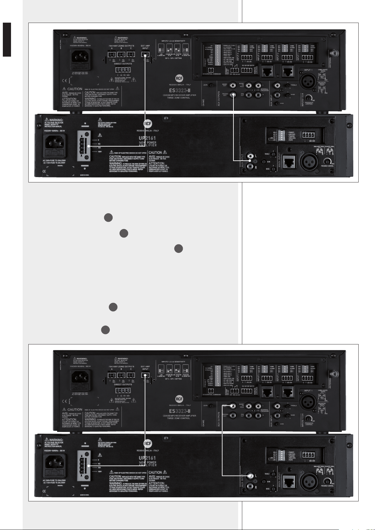
54
ITALIANO
B) ES 3323: ANNUNCI AMPLIFICATORE ESTERNO: MUSICA
COLLEGAMENTI NECESSARI:
- collegare l’uscita MUSIC OUT
26
all’ingresso audio dell’amplicatore esterno;
- collegare l’uscita (per i diffusori) a tensione costante 100 V (/ 70 V) dell’amplicatore
esterno all’ingresso EXT AMP INPUT
32
;
IMPOSTAZIONI DEI “DIP-SWITCH” DEL GRUPPO PRESET
27
:
- DIP 9 su OFF;
- DIP 10 su ON;
- DIP 11 su ON (abilita i segnali dei canali 1÷4 verso l’amplicatore interno);
- DIP 12 su OFF (musica disattivata verso l’amplicatore interno).
ESEMPIO DI COLLEGAMENTO AD UN AMPLIFICATORE RCF UP 2321:
- collegare l’uscita MUSIC OUT
25
all’ingresso audio AUX INPUT dell’amplicatore
addizionale UP 2321;
- collegare l’uscita a tensione costante 100 V (/ 70 V) dell’amplicatore UP 2321
all’ingresso EXT AMP INPUT
32
.
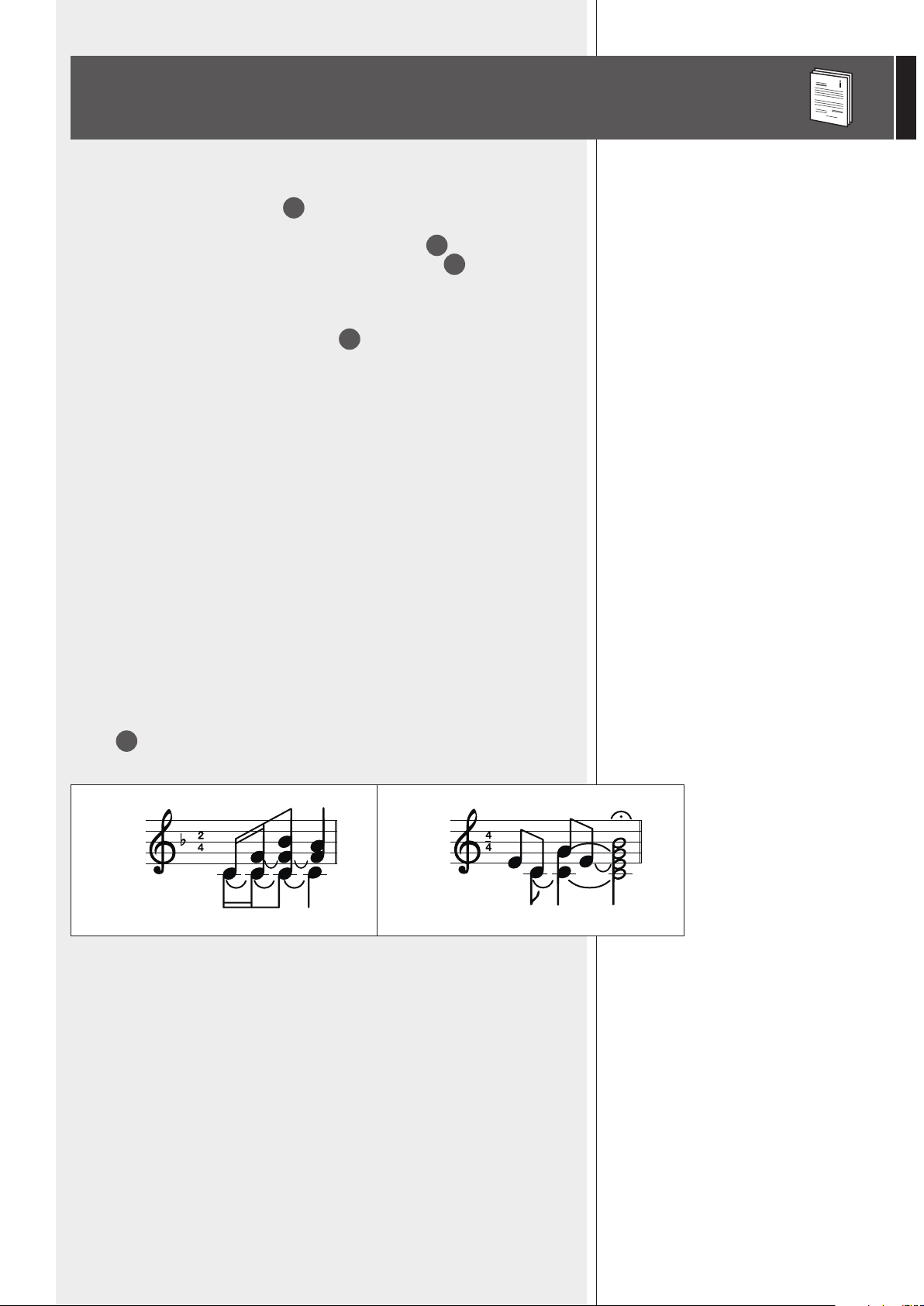
55
ITALIANO
“SEQUENTIAL COMMAND”
Il comando SEQUENTIAL COMMAND
29
ha la priorità massima ed attiva la riproduzione
continua (verso tutte le zone) della melodia di preavviso “chime” (corta o lunga, a
seconda dell’impostazione del dip-switch 7 del gruppo PRESET
27
) oppure del segnale
d’allarme (congurabile tramite il dip-switch 8 del gruppo PRESET
27
) in modo
OVERRIDE.
MODALITÀ TEMPORANEA O BI-STABILE “SMART” DELLA PRIORITÀ DEI CANALI 2 E 3
Mediante i dip-switch 5 e 6 del gruppo PRESET
27
, è possibile attivare le priorità relative
ai canali 2 e 3 in modalità temporanea, ovvero la priorità è mantenuta solo n quando il
relativo comando è attivo, oppure in modo bi-stabile (on / off), che commuta il suo stato
ad ogni comando ad impulso.
NOTA: LA MODALITÀ PRESCELTA SI APPLICA SIA ALLA BASE MICROFONICHE BM3001 (SE PRESENTI), SIA QUANDO
SI UTILIZZANO I COMANDI DI PRIORITÀ (DISPONIBILE NEI CONNETTORI RIMOVIBILI), MA MAI ALLE BASI MICROFONICHE
BM 3003.
IMPOSTARE IL DIP-SWITCH 5 (PER L’INGRESSO 2) E/O IL DIP-SWITCH 6 (PER L’INGRESSO 3) DEL GRUPPO PRESET
SU OFF SE SONO COLLEGATE 1 O PIÙ BASI MICROFONICHE BM 3003.
ULTERIORI INFORMAZIONI
GRUPPO DI 4
MICROINTERRUTTORI
/ DIP-SWITCH PER CIASCUN CANALE (DA 1 A 4)
In ciascun canale è possibile impostare la sensibilità d’ingresso (con o senza
alimentazione PHANTOM), inserire un ltro passa-alto ed abilitare la melodia di preavviso
“chime”, la quale è riprodotta ogni volta che si attiva la priorità.
INFORMAZIONI SULLA MELODIA DI PREAVVISO “CHIME”
La melodia di preavviso “chime” non è riprodotta quando si utilizza la funzione VOX del
canale 1, ma solo quando si attiva un comando di priorità.
La scelta della melodia (corta o lunga) si effettua tramite il dip-switch 7 del gruppo
PRESET
27
.
Durante il tempo di riproduzione della melodia di preavviso (pochi secondi), nella
modalità a singolo amplicatore, il segnale della sorgente musicale (interna od esterna
tramite l’ingresso ausiliario AUX INPUT) non è diffuso.
MEMORIZZAZIONE
Tutte le impostazioni attuabili mediante i vari tasti del pannello frontale sono
automaticamente memorizzate trascorsi 10 secondi dall’ultimo tasto premuto.
Durante il funzionamento, se è attivo un evento prioritario, è possibile cambiare lo
stato degli indicatori coincidente con la pressione di ciascun tasto, ma la conseguente
attuazione funzionale e memorizzazione avviene solo quando cessa l’evento prioritario.
SHORT (corta) LONG (lunga)
56
ITALIANO
BASI MICROFONICHE RCF BM 3001 E BM 3003
I canali 2 e 3 hanno ciascuno un ingresso con connettore RJ 45, al quale è possibile
collegare 2 tipi di basi microfoniche RCF (non incluse):
- BM 3001 (per soli annunci generali);
- BM 3003 (per annunci selettivi su 3 zone e la possibilità concatenare no a 12 basi
microfoniche sulla stessa linea).
Se si utilizzano basi microfoniche BM 3001, è possibile connetterne una sola per ciascun
ingresso RJ 45 (max. 2: una all’ingresso 2, una all’ingresso 3).
La priorità e la modalità di funzionamento del tasto della base microfonica BM 3001
dipende dalle varie impostazioni già descritte.
A CIASCUNA BASE MICROFONICA BM3001, È POSSIBILE ASSEGNARE LA FUNZIONE SMART MEDIANTE I
DIP-SWITCH 5 (PER L’INGRESSO 2) E 6 (PER L’INGRESSO 3) DEL GRUPPO PRESET
27
.
ES 3323-II identica se è collegata una console BM 3001 mediante l’attivazione della
modalità “LINEA con PHANTOM” nel rispettivo canale, pertanto è necessario impostare
correttamente i “dip-switch” 3 e 4
16
degli ingressi (entrambi su ON).
SE SI UTILIZZANO BASI MICROFONICHE BM 3003, È POSSIBILE COLLEGARE A
CIASCUN INGRESSO RJ 45:
- una singola base microfonica BM 3003 (senza alimentatore supplementare);
- una catena composta da max. 12 BM 3003 utilizzando un alimentatore supplementare.
Dopo aver connesso una o più basi microfoniche BM 3003, impostare correttamente
i “dip-switch” 3 e 4
16
del rispettivo ingresso nella modalità “LINEA”
(entrambi su OFF).
Le basi microfoniche BM 3003 funzionano sempre in modo SMART; impostare / lasciare
su OFF i dip-switch 5 (per l’ingresso2) e 6 (per l’ingresso 3) del gruppo PRESET
27
(funzione SMART).
È POSSIBILE COLLEGARE UNA BASE MICROFONICA BM 3001 AD UN INGRESSO
RJ 45 ED UNA (O PIÙ) BM 3003 ALL’ALTRO, QUINDI LE COMBINAZIONI
AMMESSE SONO:
- nessuna base microfonica;
- 1 x BM 3001;
- 2 x BM 3001 (una ad un ingresso, una all’altro);
- max. 12 x BM 3003 (ad un solo ingresso);
- max. 12 x BM 3003 (ad un ingresso) + 1 x BM 3001 (all’altro ingresso);
- max. 24 x BM 3003 (max. 12 per ciascun ingresso).
IMPORTANTE: NON È AMMESSO COLLEGARE ALLO STESSO INGRESSO BASI MICROFONICHE DIVERSE!
Quando si concatenano più basi microfoniche BM 3003 nella stessa linea, la prima BM
3003 (collegata direttamente all’amplicatore ES 3323) non necessita dell’alimentatore
supplementare, mentre tutte le altre a seguire sì.
Per il funzionamento specico delle basi microfoniche, riferirsi ai rispettivi manuali d’uso.
Durante la diffusione della melodia di preavviso “chime” (se abilitata), il microfono è
(momentaneamente) disabilitato.
Le basi microfoniche possono essere disattivate da eventi con livello di priorità superiore
rispetto al canale (2 o 3) a cui sono collegate.
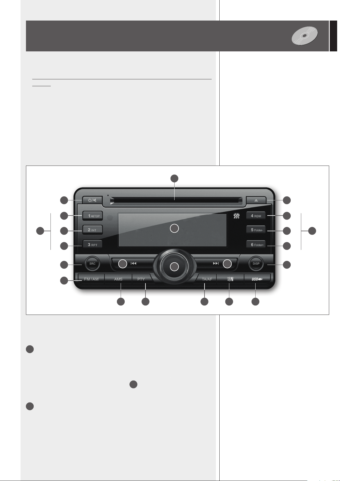
57
ITALIANO
1
Pulsante per l'accensione o lo spegnimento del (solo) lettore
CD/USB – MP3/WMA – sintonizzatore radio e la sua messa in MUTE.
Se il lettore è spento, premere (e rilasciare) questo tasto per accenderlo.
Se il lettore è acceso, premere (e rilasciare) questo tasto per metterlo in MUTE (“MUTE” è
mostrato sul display).
Premerlo ancora (o ruotare il controllo del volume
4
) per ripristinare il livello precedente.
Premerlo e tenerlo premuto (2 secondi) per spegnere il solo lettore.
2
Pulsante SRC (“source”, sorgente): premere (una o più vole) per selezionare tra la
radio, CD (quando inserito), USB (se una memoria USB è inserita), l'ingresso AUX INPUT
del lettore ed un eventuale dispositivo “Bluetooth” (se presente e correttamente abbinato
al lettore).
NOTE SUI COMPACT DISC
- Usare solo CD audio, CD-R e CD-RW da 12 cm; quelli da 8 cm non possono essere
utilizzati.
- Non usare CD danneggiati o con forma irregolare.
- Tenere i CD puliti ed afferrarli sempre dal bordo (senza toccarne la supercie con le
dita). Per pulire i CD, utilizzare un panno pulito, morbido ed asciutto, iniziando dal
centro e procedendo verso l’esterno. Non usare alcool, sostanze solventi o detergenti.
- Non mettere etichette adesive sui CD e non utilizzare CD sui quali sono già stati apposti
adesivi.
- Riporre i CD nella loro custodia quando non sono utilizzati.
- Non lasciare i CD vicino a fonti di calore o comunque esposti a temperature elevate
oppure alla luce diretta del sole (es. su cruscotti di automobili).
- Alcuni tipi di CD registrabili (CD-R) o riscrivibili (CD-RW) potrebbero non essere letti
correttamente.
USO DEL LETTORE CD/USB – MP3/WMA E
SINTONIZZATORE RADIO
1 19
7 10
8
181715 1614
11
9 12
132
3
20 20
21
22
5 6
4
PANNELLO FRONTALE
PANNELLO FRONTALE

58
ITALIANO
3
Pulsante FM/AM: selezione della banda del sintonizzatore tra modulazione di
frequenza FM (3 gruppi: FM1, FM2, FM3) ed onde medie in modulazione d'ampiezza AM
(2 gruppi: MW1, MW2).
4
Controllo (di tipo “encoder”) di volume e pulsante per la selezione dei parametri.
Se ruotato in senso orario, aumenta il volume del (solo) lettore CD/USB – MP3/WMA e
sintonizzatore radio; in senso antiorario, abbassa il volume.
Se premuto, cambia il parametro modicabile (ruotando il controllo):
volume (VOL 0 ÷ 47) → bass toni bassi (BAS -7 ÷ +7) → toni alti (TRE -7 ÷ +7) →
bilanciamento tra canali (BAL 10L ÷ 10R; 10L = solo canale sinistro, 0 = centro, 10R =
solo canale destro).
IL PARAMETRO DI BILANCIAMENTO TRA I CANALI DESTRO E SINISTRO (BAL) È SOLO PER L'USCITA STEREO INTERNAL
PROGRAM. LASCIARLO SOLITAMENTE A 0 (CENTRO) IN MODO DA INVIARE ALL'AMPLIFICATORE UN SEGNALE MONO
CHE SIA LA SOMMA EQUA DEI CANALI (DESTRO E SINISTRO).
Se mantenuto premuto per più di 2 secondi, permette di accedere al menù delle funzioni
(vedere il relativo paragrafo).
5
│◄◄ (tasto “indietro”)
RADIO:
- premere per un istante il tasto “indietro” per avviare la ricerca automatica della stazione
precedente (premere di nuovo per fermarla);
- tener premuto il tasto “indietro” per almeno 2 secondi per accedere alla ricerca manuale
(il display indica MANU ON), in modo da diminuire la frequenza in passi da 0,05 MHz
(FM) ad ogni pressione. Trascorsi 5 secondi dall'ultima pressione del tasto, la ricerca
manuale sarà automaticamente disattivata (il display indica MANU OFF).
CD audio e le MP3 / WMA:
- premere per un istante il tasto “indietro” per riavviare la traccia corrente (dopo i primi
10 secondi di riproduzione);
- premere una o più volte il tasto “indietro” per selezionare tracce precedenti;
- tener premuto il tasto “indietro” per far indietreggiare velocemente la traccia corrente.
LA SELEZIONE DELLE TRACCE (E DELLE CARTELLE “FOLDER”) È CICLICA: INDIETREGGIANDO, DOPO LA PRIMA TRACCIA
SI RITORNA ALL'ULTIMA.
6
►►│ tasto “avanti”
RADIO:
- premere per un istante il tasto “avanti” per avviare la ricerca automatica della stazione
successiva (premere di nuovo per fermarla);
- tener premuto il tasto “avanti” per almeno 2 secondi per accedere alla ricerca manuale
(il display indica MANU ON), in modo da incrementare la frequenza in passi da 0,05
MHz (FM) ad ogni pressione. Trascorsi 5 secondi dall'ultima pressione del tasto, la
ricerca manuale sarà automaticamente disattivata (il display indica MANU OFF).
CD audio e le MP3 / WMA:
- premere una o più volte il tasto “avanti” per selezionare tracce successive;
- tener premuto il tasto “avanti” per far avanzare velocemente la traccia corrente.
LA SELEZIONE DELLE TRACCE (E DELLE CARTELLE “FOLDER”) È CICLICA: AVANZANDO, DOPO L'ULTIMA TRACCIA SI
RITORNA ALLA PRIMA.
7
Pulsante ►║ TOP (solo CD audio e le MP3 / WMA)
Se premuto per un istante, mette la riproduzione in pausa (oppure la toglie, se già presente);
se tenuto premuto per qualche secondo, riporta a capo la lettura del supporto (CD o USB)
selezionato.
8
Pulsante INT “introduzione” (solo CD audio e le MP3 / WMA)
Premere per attivare INT ON / disattivare INT OFF la riproduzione (in sequenza) dei soli
primi 10 secondi (l’introduzione) di ciascuna traccia.

59
ITALIANO
9
Pulsante RPT “ripetizione” (solo CD audio e le MP3 / WMA)
CD audio: attiva RPT TRK / disattiva RPT OFF la (continua) ripetizione della traccia
selezionata.
File MP3 / WMA: RPT TRK (ripetizione continua della traccia selezionata) → RPT FOLD
(ripetizione continua, in sequenza, delle tracce della sola cartella “folder” selezionata) →
RPT OFF (riproduzione normale, senza ripetizioni).
10
Pulsante RDM “random, casuale” (solo CD audio e le MP3 / WMA)
Attiva RDM ON / disattiva RDM OFF la riproduzione casuale delle tracce.
11
Pulsante Folder– (solo le MP3 / WMA)
Se premuto per un istante, è selezionata la cartella precedente (FOLDER <<); se tenuto
premuto per qualche secondo, la riproduzione salta indietro di 10 tracce (10TRK <<).
12
Pulsante Folder+ (solo le MP3 / WMA)
Se premuto per un istante, è selezionata la cartella successiva (FOLDER >>); se tenuto
premuto per qualche secondo, la riproduzione salta avanti di 10 tracce (10TRK >>).
13
Pulsante DISP (“display”): premere per cambiare sequenzialmente le informazioni
(solo quelle disponibili) visualizzate sul display.
14
Pulsante AMS “auto memory scan”, scansione e memorizzazione automatica (solo
radio).
Se premuto per un istante, permette di visualizzare sul display ed ascoltare in sequenza
(per circa 5 secondi ciascuna) tutte le emittenti memorizzate della stessa banda (18 in
modulazione di frequenza FM oppure 12 in modulazione d'ampiezza MW); se tenuto
premuto per qualche secondo, si attiva la scansione automatica delle emittenti con segnale
più forte e la loro memorizzazione in tutte le locazioni di memoria (18 in FM oppure 12
in MW).
Attenzione: la scansione automatica cancella tutte le emittenti precedentemente
memorizzate !
IL PULSANTE AMS SI UTILIZZA ANCHE PER LA RICERCA DI FILE MP3 (VEDERE IL PARAGRAFO “RICERCA FILE MP3”).
15
Pulsante PTY “programme type” (solo radio FM)
Le emittenti radiofoniche con servizio RDS (“Radio Data System”) possono fornire un
segnale identicativo del tipo di programma.
Per cercare una stazione che trasmetta un certo tipo di musica o un particolare programma
parlato, premere il pulsante PTY una volta e ruotare il controllo di volume
4
per
scegliere tra: POP M (musica pop), ROCK M (musica rock), EASY M (musica leggera),
LIGHT M (musica classica leggera), CLASSICS (classici), OTHER M (altri generi),
WEATHER (meteo), FINANCE (economia e nanza), CHILDREN (programmi per ragazzi),
SOCIAL (programmi sociali), RELIGION (religione), PHONE IN (forum, opinioni), TRAVEL
(viaggi), LEISURE (svago), JAZZ (musica jazz), COUNTRY (musica country), NATION
M (musica nazionale), OLDIES (vecchi successi), FOLK M (musica folk), DOCUMENT
(documentari), TEST, NEWS (ultime notizie), AFFAIRS (attualità), INFO (informazioni),
SPORT, EDUCATE (programmi educativi), DRAMA (commedia e teatro), CULTURE
(programmi culturali), SCIENCE (programmi scientici), VARIED (vari generi).
La ricerca (PTY SEEK) si attiva automaticamente dopo 2 secondi dalla selezione del
programma.
Se non è trovata alcuna stazione con le caratteristiche desiderate, il display indica NO PTY.
Premere di nuovo il tasto PTY per annullare la ricerca.

60
ITALIANO
16
Pulsante TA/AF “trafc announcements / alternative frequency”
(annunci sul trafco e frequenza alternativa, solo radio FM)
Alcune emittenti radiofoniche con servizio RDS (“Radio Data System”) forniscono
periodicamente anche informazioni sul trafco; tali stazioni sono identicabili tramite
l'indicazione TP sul display.
Se il pulsante è premuto per un istante:
- quando si è sintonizzati su un'emittente che fornisce tale servizio, si attiva (appare
l'indicazione TA sul display) o disattiva la modalità di ricezione degli annunci sul trafco
con un volume prestabilito (vedere il paragrafo “MENU' DELLE FUNZIONI”);
- quando si è sintonizzati su un'emittente che NON trasmette informazioni sul trafco, a
seconda delle impostazioni del parametro TA nel menù delle funzioni, si attiva la ricerca
automatica (sul display: TA SEEK) di una stazione che invece fornisce tale servizio
oppure è indicata semplicemente la sua mancanza (sul display: NO TA/TP).
Se il pulsante è tenuto premuto per qualche secondo si attiva (appare l'indicazione AF sul
display) o disattiva la possibilità di utilizzare una frequenza alternativa (una stazione con
programmazione simile) quando non sia più possibile la buona ricezione dell'emittente
scelta.
SE LA FUNZIONE DELLA FREQUENZA ALTERNATIVA NON È ATTUALMENTE DISPONIBILE, SUL DISPLAY L'INDICAZIONE AF
LAMPEGGIA.
Tenendo premuto il tasto PTY
15
(per almeno 2 secondi) si commuta l'opzione REGION
per la frequenza alternativa tra:
- REG ON: l'emittente selezionata può essere sostituita solo da un'altra nella
regione / zona;
- REG OFF: l'emittente selezionata può essere sostituita da un'altra qualsiasi.
EON “ENHANCED OTHER NETWORKS”
QUANDO I DATI EON SONO RICEVUTI (APPARE L'INDICAZIONE EON SUL DISPLAY), LE FUNZIONI TA ED AF SONO
IMPLEMENTATE COME SEGUE:
- TA SONO RICEVUTI GLI ANNUNCI SUL TRAFFICO SIA DELLA STAZIONE CORRENTE SIA DI ALTRE STAZIONI;
- AF LA LISTA DI FREQUENZE CON RDS È SEMPRE AGGIORNATA (NEI DATI EON) PER L'UTILIZZO DELLA FREQUENZA
ALTERNATIVA.
17
AUX INPUT (connettore jack 1/8” TRS): ingresso audio ausiliario per un dispositivo
esterno.
È necessario tirare il coperchio plastico frontale per accedere all'ingresso.
18
Porta USB
L'inserimento di una memoria USB è automaticamente rilevato. Prima di rimuoverla,
scegliere come sorgente la radio od il lettore CD o l'ingresso AUX IN premendo il tasto
SRC
2
.
È necessario tirare il coperchio plastico frontale per accedere alla porta USB.
Note sulle memorie USB:
- formattazione: FAT 12 / FAT 16 / FAT 32;
- nome dei le: 32 byte / nome dir: 32 byte / “tag”: 32 byte;
- TAG (ID3 ver. 2.0) - titolo / artista / album: 32 byte;
- supporto USB 1.1 e 2.0 (ma con velocità 1.1);
- alcune memorie USB potrebbero non essere compatibili.
19
Pulsante EJECT per l'espulsione del compact disc.
20
Pulsanti 1 ÷ 6 : tasti per la selezione / memorizzazione di 6 emittenti radiofoniche /
frequenze per ciascun gruppo (FM1, FM2, FM3, MW1, MW2).
Se un pulsante è premuto per un istante, seleziona l'emittente già memorizzata (in tale
locazione); se tenuto premuto per qualche secondo, memorizza l'attuale frequenza in
quella locazione (sul display appare il relativo numero nell'angolo in basso a destra).
21
Slot per l'inserimento del compact disc (nota: inserire un solo CD alla volta).
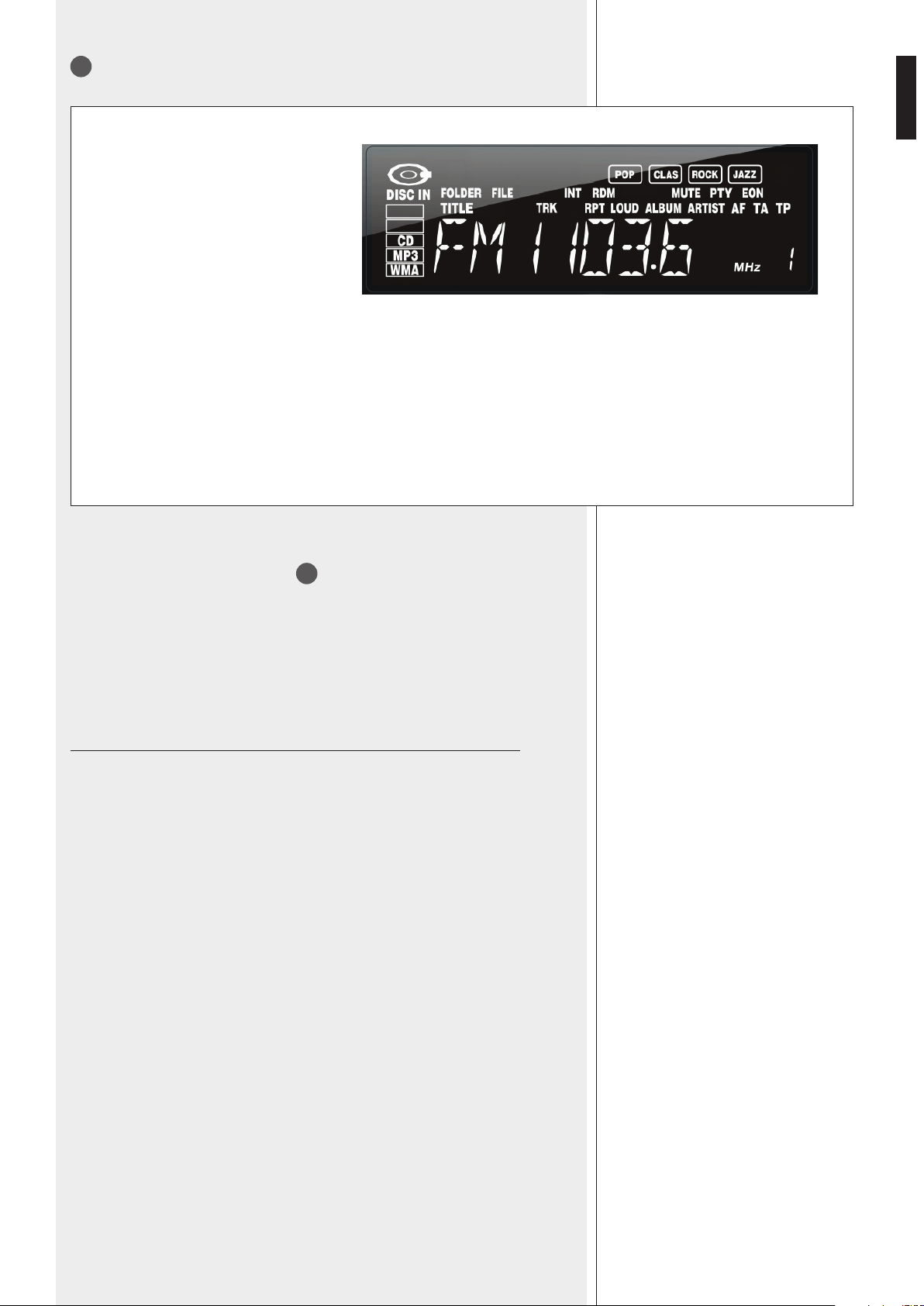
61
ITALIANO
Informazioni radio: il gruppo selezionato
(FM1, FM2, FM3, MW1, MW2), la
frequenza e se questa corrisponde
ad un locazione di memoria (indicata
nell’angolo in basso a destra).
POP – CLAS – ROCK – JAZZ:
selezione corrente DSP (equalizzazione
della musica).
INT: funzione intro
RDM: riproduzione casuale
MUTE: il lettore / la radio è in “mute”
PTY: funzione “programma” inserita
EON: “Enhanced Other Networks”
DISC IN: un “compact disc” è stato
inserito.
CD: CD audio
MP3: le MP3
WMA: le WMA
FOLDER: cartella corrente
FILE: le corrente
TITLE: titolo corrente
TRK: traccia corrente
RPT: ripetizione inserita
LOUD: “loudness” inserito
ALBUM: album corrente
ARTIST: artista corrente
AF: ricerca frequenza alternativa
abilitata
TA: funzione annunci trafco abilitata
TP: stazione con informazioni sul trafco
Tenendo premuto il controllo del volume
4
per 2 secondi, si accede al menù delle funzioni
(dal quale si esce aspettando qualche secondo senza premere il pulsante); ogni successiva
pressione cambia il parametro selezionato:
TA ALARM / SEEK *→ AF *→ TA *→ REG *→ TA VOL *→ RETUNE *→ DSP → LOUD
→ DX / LOCAL → ROLL →V-LAST / ADJ → [A-VOL]
* disponibile solo se la radio è impostata su FM.
Ruotare il controllo del volume per cambiare il valore del parametro selezionato.
TA ALARM / SEEK
Quando si è sintonizzati su un'emittente FM che non trasmette informazioni sul trafco e
si attiva la funzione TA, si può scegliere se:
- ALARM : indicare semplicemente la mancanza del servizio sul display (NO TA/TP);
- SEEK : attivare la ricerca automatica di una stazione che invece fornisce tale servizio.
AF (FREQUENZA ALTERNATIVA)
Se impostato su ON, la funzione “frequenza alternativa” è abilitata, si permette la ricerca
automatica di una stazione FM alternativa (con programmazione simile) quando non sia
più possibile la buona ricezione dell'emittente scelta.
Se impostato su OFF, la funzione “frequenza alternativa” è disabilitata.
Se impostato su LOCAL: solo le stazioni radio con segnale forte possono essere selezionate.
TA (ANNUNCI SUL TRAFFICO)
Se impostato su ON, la ricezione delle informazioni sul trafco è abilitata. Quando si è
sintonizzati su un’emittente che non trasmette informazioni sul trafco, a seconda delle
impostazioni del precedente parametro TA, si attiva la ricerca automatica (sul display: TA
SEEK) di una stazione che invece fornisce tale servizio oppure è indicata semplicemente la
sua mancanza (sul display: NO TA/TP). Se impostato su OFF, la ricezione delle informazioni
sul trafco è disabilitata.
REG (STAZIONI NELLA REGIONE)
Se impostato su ON, durante la ricerca della frequenza alternativa (AF), l’emittente FM
selezionata può essere sostituita solo da un’altra nella regione / zona; se impostato su OFF,
l’emittente FM selezionata può essere sostituita da un’altra qualsiasi.
22
Display (LCD)
MENÙ DELLE FUNZIONI
MENÙ DELLE FUNZIONI

62
ITALIANO
TA VOL : imposta il volume pressato (tra i valori 12 e 45) per gli annunci sul trafco.
RETUNE : impostazione del tempo d’intervallo tra una ricerca automatica (TA SEEK) e
quella successiva di una stazione radio che fornice informazioni sul trafco.
Se impostato su S: il tempo d’intervallo tra due ricerche è 45 secondi.
Se impostato su L: il tempo d’intervallo tra due ricerche è 3 minuti.
DSP : imposta un’equalizzazione ottimizzata per alcuni tipi di musica.
OFF (nessuna equalizzazione) → POP → ROCK → CLASSIC → JAZZ
LOUD (LOUDNESS): ON / OFF
Loudness: si tratta di un piccolo espediente per migliorare la qualità di ascolto a basso
volume di un brano musicale. Quando attivo, le frequenze più basse e quelle più alte
sono incrementate in modo da compensare la minor sensibilità dell’orecchio umano verso
l’estremità dello spettro udibile.
DX / LOCAL
Se impostato su DX: tutte le stazioni radio possono essere selezionate.
ROLL
Se impostato su ON, tutte le informazioni sulla traccia / le corrente sono automaticamente
e sequenzialmente visualizzate sul display.
V-LAST / ADJ
Scelta se il controllo di volume del lettore CD/USB – MP3/WMA e sintonizzatore radio
all’accensione debba essere:
- LAST: allo stesso livello presente prima dello spegnimento;
- ADJ: ad un livello preimpostato dal parametro successivo A-VOL.
A-VOL (parametro attivo solo se il precedente V-LAST / ADJ è impostato su ADJ): volume
pressato (0 ÷ 47) del lettore CD/USB – MP3/WMA e sintonizzatore radio all’accensione.
- MP3 (MPEG Audio Layer 3) e WMA (Windows Media Audio) sono standard di
compressione audio.
- Questo prodotto permette la riproduzione di le MP3 / WMA su CD-ROM, CD-R, CD-RW
e memorie USB e riceve dati da dispositivi BLUETOOTH; sono visualizzati (se disponibili),
il titolo del brano, l'artista e l'album (no a 16 caratteri, ID3 TAG versione 2.0 richiesta).
- Non è supportata la lettura di CD-R – CD-RW scritti con la modalità a pacchetti (“packet
write”).
- I dischi CD-R devono essere nalizzati.
- L'estensione dei le deve essere .mp3 oppure .wma.
- Il livello massimo di directory (o “cartelle” / “folder”) in un supporto è 8, inclusa la
radice (”root”).
- Il numero max. di le MP3/WMA presenti su un supporto non deve essere maggiore
di 256.
- Se un CD contiene sia tracce audio sia le MP3/WMA , il lettore riprodurrà solamente
le tracce audio.
- Assicurarsi che durante la masterizzazione di un CD-R con le MP3 / WMA, questo
sia formattato come “disco dati” e non “disco audio”. È consigliabile non inserire nel
CD-R le che non siano MP3 / WMA (o cartelle non necessarie), altrimenti l'avvio della
riproduzione potrebbe impiegare un tempio più lungo.
- Con alcuni tipi di CD-R / CD-RW, i dati potrebbero non essere scritti correttamente; è
consigliabile utilizzare supporti di qualità elevata.
- Quando si riproduce un le MP3 con velocità di lettura variabile (“Variable Bit Rate”), il
tempo indicato sul display potrebbe non essere corretto; anche l'opzione INT potrebbe
non funzionare correttamente.
- Si consiglia di utilizzare le MP3 con frequenza di campionamento (sampling frequency)
di 44.1 kHz ed un “bit rate” sso di almeno 128 kbps (se più alto, es. 192 kbps, si
ottiene una qualità migliore).
- Il lettore potrebbe riprodurre le tracce non nell'ordine scritto sul disco o memoria USB.
NOTE SUI FILE MP3 / WMA
NOTE SUI FILE MP3 / WMA
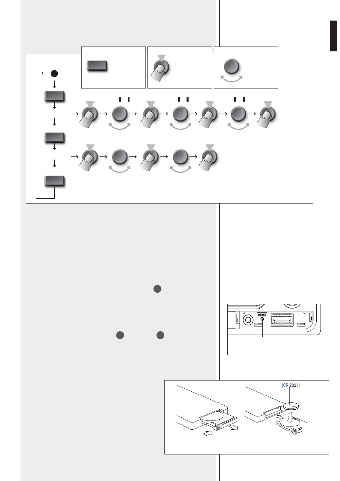
63
ITALIANO
AMS
AMS
AMS
TRK SCH
FILE SCH
TRK 000 ÷ 090TRK 000 ÷ 009 TRK 000 ÷ 200
FILE
FOLDER
AMS
PREMERE IL
TASTO “AMS”
PREMERE IL
CONTROLLO DI
VOLUME
RUOTARE IL
CONTROLLO DI
VOLUME
TRACK
SELECTION (no.)
SELEZIONE DEL FILE
RICERCA FILE MP3 (/ WMA)
RICERCA FILE
MP3 (/ WMA)
DISPOSITIVI “BLUETOOTH”
DISPOSITIVI “BLUETOOTH”
TASTO RESET
TELECOMANDO
TELECOMANDO
“Bluetooth” è una tecnologia per lo scambio dati, senza cavi e su distanze brevi, tra
dispositivi ssi e mobili (es. telefoni cellulari). Per collegare un dispositivo esterno al lettore:
1. attivare la funzione “Bluetooth” sul dispositivo esterno;
2. sempre sul dispositivo esterno, avviare la ricerca di apparecchi con “Bluetooth” attivo;
dovrebbe apparire la scritta “RCF”;
3. abbinare il dispositivo esterno ad “RCF” inserendo il codice (/ password) “1234”;
4. avviare la riproduzione di un le audio sul dispositivo esterno, il quale dovrebbe ora
essere incluso tra le sorgenti del lettore (usare il tasto SRC
2
per cambiare sorgente).
Premere il tasto RESET (tramite un piccolo oggetto appuntito) solo nel caso che il lettore /
radio non funzioni correttamente o sia da inizializzare.
Il tasto RESET si trova tra l'ingresso AUX IN
17
e la porta USB
18
.
Il telecomando necessita di una batteria al litio CR 2025
(3 V), da sostituire non appena il telecomando non
funziona più correttamente. Assicurarsi che la polarità
della batteria sia corretta.
Per inserire o sostituire la batteria:
1. estrarre il supporto della batteria tenendo premuto il suo
fermo;
2. inserire la batteria al litio (a bottone) con il segno + rivolto
verso l'alto;
3. reinserire il supporto con la nuova batteria nel telecomando.
RESET
1. 2.
3.
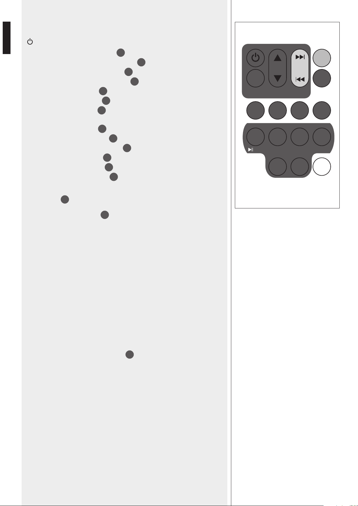
64
ITALIANO
Durante l’uso, puntare il telecomando (tenendolo per il verso giusto) in direzione
dell’apparecchio.
ON-OFF Accensione o spegnimento del (solo) lettore / radio.
SEL Stessa funzione del controllo di volume
4
quando premuto.
VOL ▲(+)▼(–) Stessa funzione del controllo di volume
4
quando ruotato.
│◄◄ (back) Stessa funzione del rispettivo tasto
5
sul pannello frontale.
►►│ (forward) Stessa funzione del rispettivo tasto
6
sul pannello frontale.
SRC Stessa funzione del tasto SRC
2
.
AMS Stessa funzione del tasto AMS
14
.
TA Stessa funzione del tasto TA/AF
16
, ma solo per TA on/off.
AF / REG (vedere sotto *)
PTY Stessa funzione del tasto PTY
15
.
BAND Stessa funzione del tasto FM/AM
3
.
►║
TOP (1) Stessa funzione del tasto ►║ TOP
7
.
INT (2) Stessa funzione del tasto INT
8
.
RPT (3) Stessa funzione del tasto RPT
9
.
RDM (4) Stessa funzione del tasto RDM
10
.
I tasti
da 1 a 6 hanno anche la funzione di richiamo / memorizzazione di 6 emittenti radiofoniche
(vedere il punto
20
).
DISP Stessa funzione del tasto DISP
13
.
* AF / REG “alternative frequency / region” (solo radio, emittenti FM con RDS)
Se il tasto è premuto per un istante, si attiva (appare l'indicazione AF sul display)
o disattiva la possibilità di utilizzare una frequenza alternativa (una stazione con
programmazione simile) quando non sia più possibile la buona ricezione dell'emittente
scelta.
Se il tasto è tenuto premuto per qualche secondo, si commuta l'opzione “region” per la
frequenza alternativa tra:
- REG ON (l'emittente selezionata può essere sostituita solo da un'altra nella regione /
zona);
- REG OFF (l'emittente selezionata può essere sostituita da un'altra qualsiasi).
ERROR 1 / 2
Premere per almeno 2 secondi il tasto EJECT
19
per espellere il compact disc. Se il CD
non è stato espulso, premere con un oggetto appuntito il piccolo tasto RESET e poi di
nuovo EJECT (per almeno 2 secondi).
Nel caso non sia possibile espellere il CD, contattare il rivenditore od un centro
d'assistenza autorizzato.
ERROR 3
Il compact-disc è stato inserito sottosopra.
ERROR 4
Il formato del compact disc non è supportato oppure i dati (/ i le) non sono del tipo
corretto.
SEL
VOL
SRC
AMS
SEARCH
BANDPTYAF/REGTA
4321
DISP65
TOP
INT RPT RDM
MENU
CODICI D’ERRORE
CODICI D’ERRORE
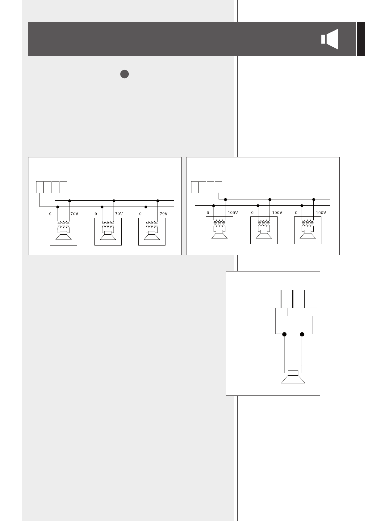
65
ITALIANO
COLLEGAMENTO DEI DIFFUSORI ACUSTICI
USCITE DIRETTE “DIRECT OUTPUTS”
34
Utilizzare una sola uscita tra le 2 disponibili: 100 V, 70 V
USCITE A TENSIONE COSTANTE 70 / 100 V
- Ogni diffusore deve avere un trasformatore di linea con tensione d’ingresso uguale a
quella della linea (70 / 100 V).
- La somma delle potenze di tutti i diffusori collegati (alle uscite dirette ed a quelle separate
per zona) non deve essere superiore a quella massima erogabile dall’amplicatore (320 W).
USCITA CON POTENZA 2 W PER DIFFUSORE MONITOR A BASSA IMPEDENZA (4 Ω)
L’impedenza del diffusore non deve essere inferiore a 4 Ω.
NOTA: UN’IMPEDENZA UGUALE A 4 Ω PERMETTE LA MASSIMA EROGAZIONE DI POTENZA (2 W); UN’IMPEDENZA
SUPERIORE COMPORTA UNA RIDUZIONE DELLA POTENZA EROGATA (ES. 8 Ω: CIRCA 1 W; 16 Ω: CIRCA 0,5 W);
UN’IMPEDENZA INFERIORE A 4 Ω SOVRACCARICA L’USCITA.
100 V CONSTANT VOLTAGE LINE
70 V CONSTANT VOLTAGE LINE
0 4 Ω 70V 100V0 4 Ω 70V 100V
– +
0 4 Ω 70V 100V
2 W
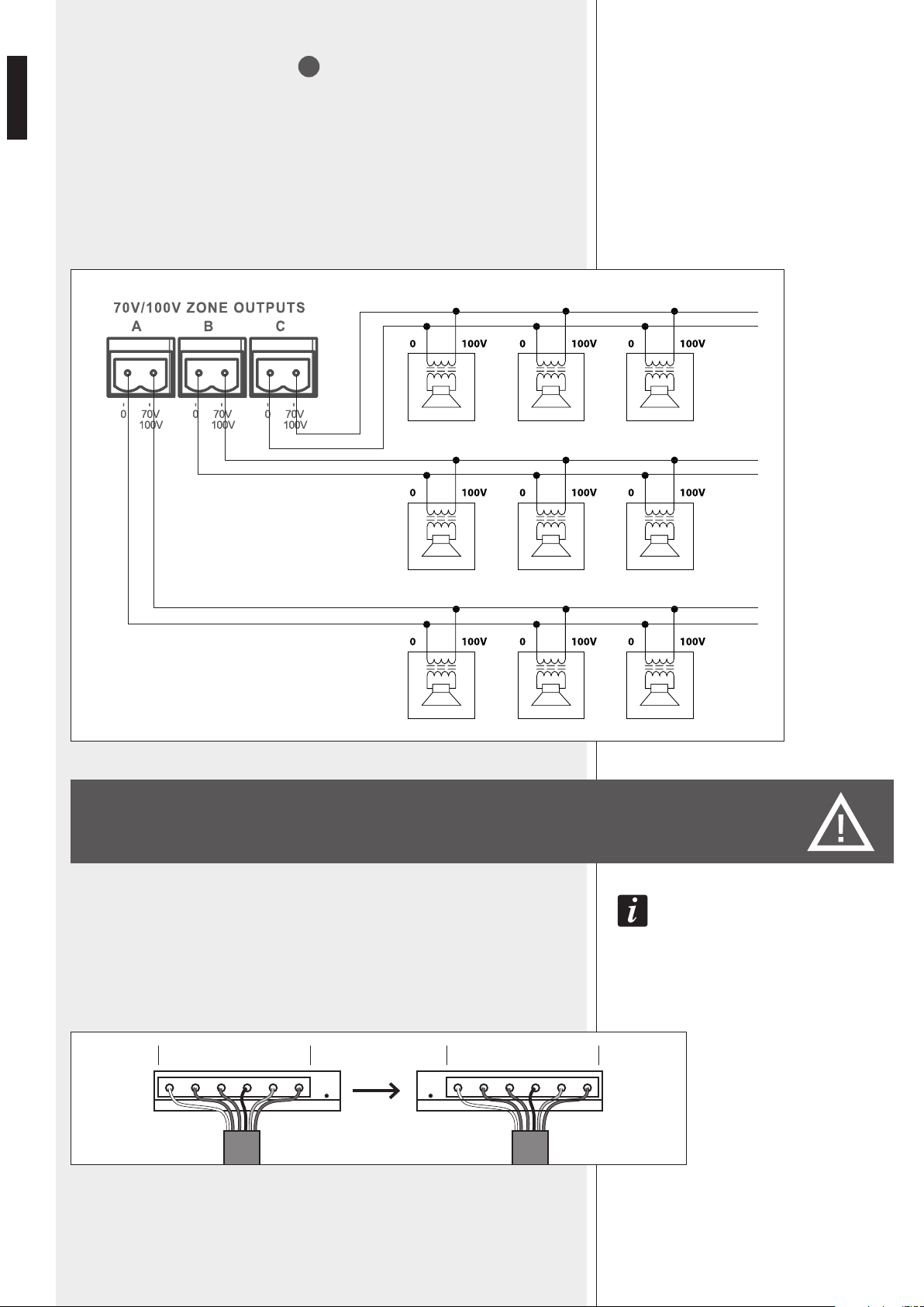
66
ITALIANO
USCITE DI ZONA “ZONE OUTPUTS”
33
Ciascuna zona dispone di un’uscita separata a tensione costante 100 V / 70 V.
L’apparecchio è normalmente predisposto in modo che la tensione (comune) alle 3 uscite
di zona sia 100 V; per selezionare 70 V, contattare un centro d’assistenza autorizzato.
- Ogni diffusore deve avere un trasformatore di linea con tensione d’ingresso uguale a
quella della linea (70 / 100 V).
- La somma delle potenze di tutti i diffusori collegati (alle uscite dirette ed a quelle separate
per zona) non deve essere superiore a quella massima erogabile dall’amplicatore (320 W).
IMPORTANTE: LA SEGUENTE OPERAZIONE RIGUARDA IL SOLO PERSONALE QUALIFICATO E NON DEVE ESSERE
EFFETTUATA DIRETTAMENTE DALL’UTENTE.
All’interno dell’apparecchio, sopra il trasformatore al centro è ssata una scheda dove
è presente il connettore J3 “ZONE SELECTOR”, il quale è normalmente posto nella
posizione 100 V.
Per selezionare 70 V, spostare il connettore di un contatto verso destra.
A
B
C
100 V
J3
70 V
CAMBIO TENSIONE 100 V / 70 V (COMUNE) ALLE
USCITE DI ZONE “ZONE OUTPUTS”
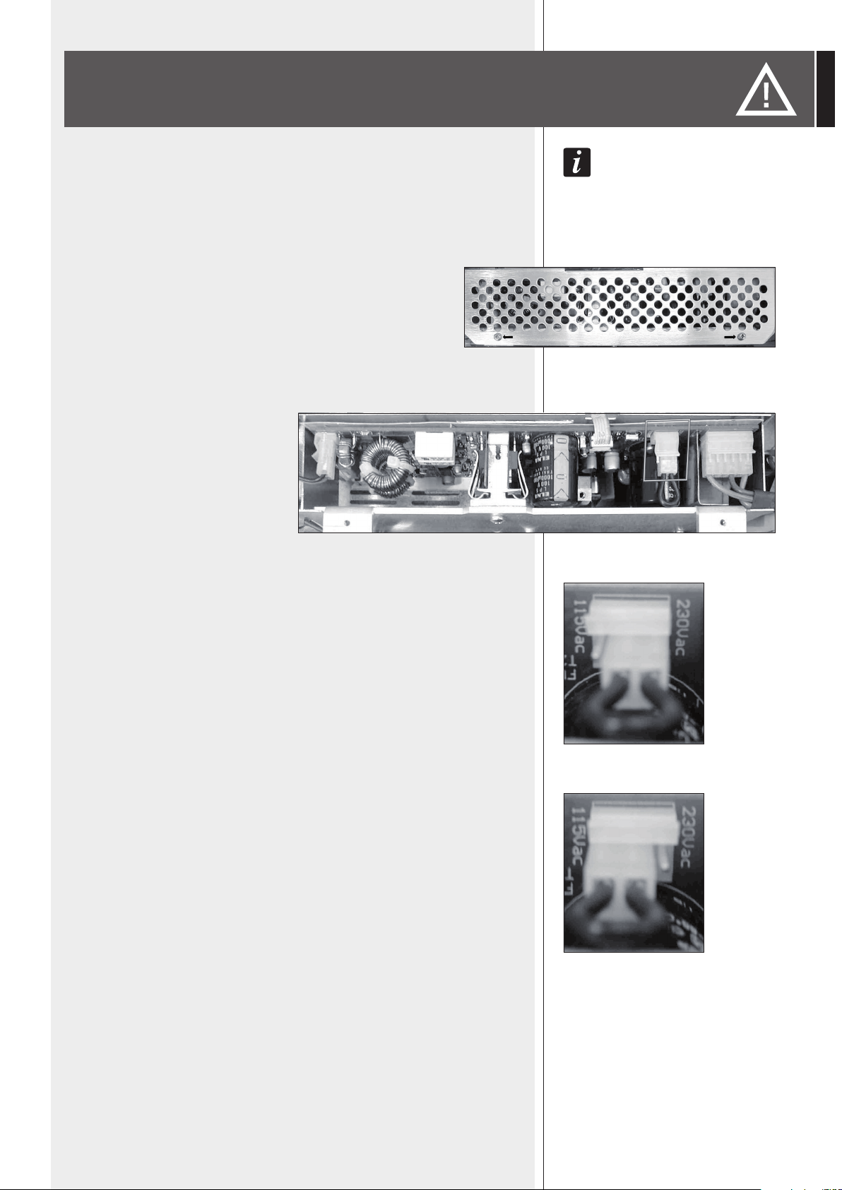
67
ITALIANO
LE SEGUENTI OPERAZIONI NON DEVONO ESSERE EFFETTUATE DIRETTAMENTE DALL’UTENTE.
Togliere la tensione dall’apparecchio (staccando il cavo d’alimentazione dalla presa di rete).
Rimuovere il coperchio superiore dell’apparecchio.
Il circuito di alimentazione si trova sotto lo schermo metallico forato
(vedere la foto 1), il quale va rimosso svitando le 2 viti.
FOTO 1
Individuare il connettore per il cambio
di tensione 230 / 115 V (nella foto 2 è
evidenziato con un quadrato).
Con tensione di rete 230 V, porre (o lasciare) il connettore nella posizione 230Vac (vedere
la foto 3) in accordo con la serigraa del circuito stampato (in modo che il polo centrale sia
collegato a quello destro, guardando il connettore frontalmente).
Con tensione di rete 115 V, porre (o lasciare) il connettore nella posizione 115Vac (vedere
la foto 4) in accordo con la serigraa del circuito stampato (in modo che il polo centrale sia
collegato a quello sinistro, guardando il connettore frontalmente).
Rimontare lo schermo metallico dell’alimentatore ed il coperchio superiore dell’apparecchio.
Prima di collegare l’apparecchio rete, assicurarsi che il fusibile inserito nel connettore per
l’alimentazione (posto sul pannello posteriore) sia quello corretto per la tensione in uso
(leggere le indicazioni poste sotto il connettore stesso).
FOTO 2
FOTO 3
FOTO 4
CAMBIO TENSIONE DI FUNZIONAMENTO
DELL’APPARECCHIO

68
ITALIANO
SPECIFICHE TECNICHE
AMPLIFICATORE
POTENZA D’USCITA
DISTORSIONE (A 1 KHZ, POTENZA NOMINALE)
CONTROLLO PRESENCE (INGRESSI 1 ÷ 4)
FILTRO PASSA-ALTO (INGRESSI 1 ÷ 4)
INGRESSI 1 ÷ 4, LINEA
Sensibilità d’ingresso nominale -
Livello massimo -
Rapporto segnale / rumore -
Risposta in frequenza (– 3 dB) -
Impedenza a 1 kHz -
INGRESSI 1 ÷ 4, LINEA CON PHANTOM
Sensibilità d’ingresso nominale -
Livello massimo -
Rapporto segnale / rumore -
Risposta in frequenza (– 3 dB) -
Impedenza a 1 kHz -
INGRESSI 1 ÷ 4, MIC./ MIC. CON PHANTOM
Sensibilità d’ingresso nominale -
Livello massimo -
Rapporto segnale / rumore -
Risposta in frequenza (– 3 dB) -
Impedenza a 1 kHz -
INGRESSO AUX INPUT -
Sensibilità d’ingresso nominale -
Campo di regolazione -
Livello massimo -
Rapporto segnale / rumore -
Risposta in frequenza (– 3 dB) -
CONTROLLI TONI AUX INPUT
Bass -
Treble -
TENSIONE / CORRENTE “PHANTOM POWER”
LIVELLO USCITA PRE OUT
LIVELLO USCITA PAGING OUT
LIVELLO USCITA MUSIC OUT
LIVELLO USCITA MUSIC ON HOLD
USCITE DIFFUSORI
• Bassa impedenza
• Tensione costante
320 W (RMS)
< 0,3 %
+ 9,5 dB @ 2,2 kHz
150 Hz
– 7 dBu
+ 21 dBu
80 dB
70 Hz ÷ 11,5 kHz
20 kΩ (bilanciato) / 10 kΩ (sbilanciato)
– 26 dBu
0 dBu
80 dB
70 Hz ÷ 11,5 kHz
6,5 kΩ (bilanciato)
– 56 dBu
– 28 dBu
65 dB
70 Hz ÷ 11,5 kHz
20 kΩ (bilanciato) / 10 kΩ (sbilanciato)
0 dBu (regolabile)
– 11 ÷ + 10 dBu
+ 14 ÷ 24 dBu
79 dB
40 Hz ÷ 14,5 kHz
± 8 dB a 80 Hz
± 8 dB a 13 kHz
32 V / 18 mA
0 dBm (dipende dai volumi dei canali, controllo di presenza,
controlli e selettori musica; non dipende dal controllo
MASTER su pannello frontale o remoto)
0 dBm (dipende dai volumi dei canali e dal controllo di
presenza; non dipende dal controllo MASTER su pannello
frontale o remoto)
0 dBm (dipende dai controlli e selettori della musica; non
dipende dal controllo MASTER su pannello frontale o
remoto)
0 dBm (dipende solo dal controllo
AUX INPUT GAIN)
4 Ω - potenza: 2 W
70 V (16 Ω) / 100 V (31 Ω) - potenza: 320 W

69
ITALIANO
RADIO
Banda FM
Risposta in frequenza FM
Separazione tra canali FM (1 kHz)
Reiezione intermedia FM
Reiezione immagine FM
Rapporto segnale / rumore FM
Banda AM (MW)
Ingresso antenna
CD AUDIO
Risposta in frequenza
Rapporto segnale / rumore
Distorsione T.H.D. (1 kHz)
Separazione tra canali
PROTEZIONI
Amplicatore
Carico
Alimentazione
GENERALE
Tensione di alimentazione
Potenza assorbita
Dimensioni (l, h, p)
Peso (Netto)
87,5 ÷ 108 MHz
30 Hz ÷ 15 kHz
≥ 30 dB
≥ 70 dB
≥ 50 dB
≥ 55 dB
522 ÷ 1620 kHz
75 Ω - Coassiale
20 Hz ÷ 20 kHz
≥ 80 dB
< 0,2 %
≥ 55 dB
Corto circuito, termica
DC Offset Delay, Fusibile d’uscita
Fusibili di rete
115-230V / 50-60 Hz
600 W
444 mm, 127 mm, 345 mm
10,1 kg
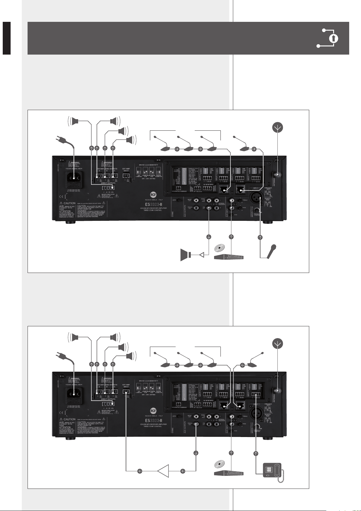
70
ITALIANO
ESEMPIO COLLEGAMENTI
A. Sistema per annunci su 3 zone utilizzando il solo amplicatore interno (la musica
non è mantenuta nelle zone non selezionate durante un annuncio).
Sono previsti: un microfono di emergenza prioritario collegato all’ingresso 1, una
base microfonica BM 3001 (ingresso 2) ed una catena di BM 3003 per gli annunci
(ingresso 3).
B. Sistema per annunci su 3 zone in modalità di doppia amplicazione “A” (è previsto
un amplicatore esterno per gli annunci).
La musica è amplicata dall’amplicatore interno ed è mantenuta nelle zone non
selezionate durante un annuncio.
Sono previsti: il collegamento alla centrale telefonica (ingresso 1) e due catene di
basi microfoniche BM 3003 per gli annunci (ingressi 2 e 3).
BM 3001
A
B
C
70 - 100 V70 - 100 V
BM 3003
DVD
A
B
C
70 - 100 V70 - 100 V
BM 3003
BM 3001
DVD

71
ITALIANO
C. Miscelazione di 4 microfoni (con controlli di livello separati) ed utilizzo della sola
uscita diretta (70 - 100 V) per i diffusori acustici.
L’uscita 4 Ω (max. 2 W) permette l’ascolto del programma diffuso tramite un
diffusore monitor dedicato.
4 ohm monitor (2 W)
70 - 100 V

10307453 RevC
2017 / 03
www.rcf.it
RCF S.p.A. Italy
Via Raffaello Sanzio, 13
42124 Reggio Emilia - Italy
Tel +39 0522 274 411
Fax +39 0522 232 428
e-mail: info@rcf.it
Except possible errors and omissions.
RCF S.p.A. reserves the right to make modications without prior notice.
Salvo eventuali errori ed omissioni.
RCF S.p.A. si riserva il diritto di apportare modiche senza preavviso.