IMPORTANT : Please read this manual
carefully before running this unit, and
save it for future reference.
© Copyright, GREE Canada, 2021
12102021
Operation Manual
Crossover Heat Pump
GWH09AGC-D3DNA2B/I - GWH09AGC-D3DNA1B/O
GWH12AGC-D3DNA2A/I - GWH12AGC-D3DNA1A/O
GWH18AGD-D3DNA2B/I - GWH18AGD-D3DNA1B/O
GWH24AGE-D3DNA2A/I - GWH24AGE-D3DNA1A/O


3
TABLE OF CONTENTS
FOREWORD
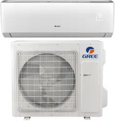
Thank you for your purchase ! This manual is the universal version for this product manu-
factured by GREE Canada. The appearance of the unit that you have purchased may differ
from the one shown in this manual, however it does not change the basic guidelines on how
to properly operate this appliance.
To ensure satisfactory operation for many years, this manual should be read carefully
before using the appliance.
After reading, keep it in a safe place. Please refer to the manual if you have any questions
about operation or if you encounter any irregularities that need to be corrected.
1. SAFETY GUIDELINES
Safety Symbols Description ........................................................................................................ 4
Exception Clauses ...................................................................................................................... 4
Compliance Statements .............................................................................................................. 5
Operations and Maintenance Safety Instructions ....................................................................... 6
2. COMPONENT SUMMARY
Indoor Unit................................................................................................................................... 7
Outdoor Unit ................................................................................................................................ 7
3. OPERATION GUIDE
Remote Control Buttons .............................................................................................................. 8
Remote Control Display Screen Indicators ................................................................................. 9
Basic Operating Instructions ..................................................................................................... 10
Function Description and Setting ...............................................................................................11
4. MAINTENANCE
Cleaning the Surface................................................................................................................. 20
Cleaning the Dust Filter............................................................................................................. 20
Pre and Post Season Maintenance........................................................................................... 21
Recycling and Disposal ............................................................................................................. 21
5. TROUBLESHOOTING
Error Codes Identication.......................................................................................................... 22
Common Malfunctions and Possible Fixes ............................................................................... 22
6. WARRANTY ............................................................................................................................... 24
Electrical products should be properly disposed.
Please recycle where facilities exist.
Check with your local authority or retailer for recycling.
4
This symbol indicates an imminently hazardous situation that, if not avoided, will
cause severe personal injury, death, or substantial property damage.
DANGER
This symbol indicates a potentially hazardous situation that, if not avoided, will or can
cause minor personal injury or property damage.
CAUTION
This symbol indicates a potentially hazardous situation that, if not avoided, can cause
severe personal injury, death, or substantial property damage.
WARNING
This symbol indicates that the items must be observed. Incorrect use may result in
personal injury or property damage.
NOTE
SAFETY GUIDELINES
SAFETY SYMBOLS DESCRIPTION
The following symbols are used throughout this manual to indicate immediate or potential hazards. It is the
owner’s responsibility to read and follow all safety information and instructions accompanying these sym
-
bols. Failure to heed safety information increases the risk of serious injury or death, property damage and/
or product damage.
EXCEPTION CLAUSES
The manufacturer will not assume any liability when personal injury or property damage is caused by the
following reasons :
1. Damage the product due to improper use or misuse of the product.
2. Modify, change, maintain or use the product with other equipment without complying with the manufac
-
turer’s instruction manual.
3. After verication, the product defect is directly caused by corrosive gas.
4. After verication, the defects are caused by mishandling during product transportation.
5. Operation, repair, maintenance of the unit without complying with the instruction manual or related
regulations.
6. After verication, the problem or dispute is caused by the quality specications or performance of parts
and components produced by other manufacturers.
7. The damage is caused by natural disasters, bad operating environment or force majeure.
If it is necessary to install, move or service the heat pump, please contact your dealer or local service
center rst. The appliance must be installed, moved or serviced by qualied technicians. Failure to do
so may result in serious damage or personal injury, or even death.
When refrigerant leaks or must be discharged during installation, maintenance or disassembly, it must
be handled by certied professionals or in accordance with local laws and regulations.
This appliance is not intended for use by persons (including children) with reduced physical, sensory or
mental capabilities or lack of experience and knowledge, unless they are given supervision or instruc
-
tion in its use by a person responsible for their safety.
Children should be supervised to ensure that they do not play with the unit.

5
SAFETY GUIDELINES
COMPLIANCE STATEMENTS
WARNING : GREE Canada has not approved any changes or modications to this device by the user. Any
changes or modications could void the user’s authority to operate the equipment.
FEDERAL COMMUNICATIONS COMMISSION (FCC) REGULATIONS
This device complies with part 15 of the FCC Rules. Operation is subject to the following two conditions :
(1) this device may not cause harmful interference, and (2) this device must accept any interference re
-
ceived, including interference that may cause undesired operation.
NOTE : This equipment has been tested and found to comply with the limits for a Class B digital device,
pursuant to part 15 of the FCC Rules. These limits are designed to provide reasonable protection against
harmful interference in a residential installation. This equipment generates, uses, and can radiate radio
frequency energy and, if not installed and used in accordance with the instructions, may cause harmful
interference to radio communications. However, there is no guarantee that interference will not occur in a
particular installation.
If this equipment does cause harmful interference to radio or television reception, which can be determined
by turning the equipment off and on, the user is encouraged to try to correct the interference by one or more
of the following measures :
● Reorient or relocate the receiving antenna ;
● Increase the separation between the equipment and receiver ;
● Connect the equipment into an outlet on a circuit different from that to which the receiver is connected ;
● Consult the dealer or an experienced radio/TV technician for help.
INDUSTRY CANADA (IC) REGULATIONS
This device complies with Industry Canada licence-exempt RSS standard(s). Operation is subject to the
following two conditions : (1) this device may not cause interference, and (2) this device must accept any
interference, including interference that may cause undesired operation of the device.
This equipment complies with FCC’s and IC’s RF radiation exposure limits set forth for an uncontrolled en
-
vironment. The antenna(s) used for this transmitter must be installed and operated to provide a separation
distance of at least 20 cm from all persons and must not be collocated or operating in conjunction with any
other antenna or transmitter. Installers must ensure that 20 cm separation distance will be maintained be
-
tween the device (excluding its handset) and users.

6
SAFETY GUIDELINES
CAUTION :
▪ This appliance is not intended for use by persons
(including children) with reduced physical, sen
-
sory or mental capabilities or lack of experience
and knowledge, unless they are given supervi
-
sion or instruction in its use by a person responsi-
ble for their safety.
▪ Children should be supervised to ensure that they
do not play with the unit.
▪ Cleaning and maintenance should not be per
-
formed by unsupervised children.
▪ If the power cord is damaged, it must be replaced
by the manufacturer, its service agent or similarly
qualied persons to avoid any hazard.
▪ Do not plug the heat pump into a multipurpose
outlet. Doing so may lead to a re hazard.
▪ Disconnect the power supply when cleaning the
heat pump. Failure to do so may result in electric
shock.
▪ Do not wash the heat pump with water to avoid
the risk of electric shock.
▪ Do not spray water on the indoor unit. This could
cause electric shock or malfunction.
▪ Do not repair the heat pump yourself. You may
expose yourself to electric shock or damage
the equipment. Please contact your local dealer
when you need to repair the appliance.
▪ When removing the dust lter, avoid touching the
ns to prevent injury.
▪ Do not extend ngers or objects into the air inlet
or outlet. Doing so could cause injury or damage.
▪ Do not spill water on the remote control, other
-
wise it could become inoperative.
▪ When cleaning the dust lter, do not use an open
ame or hair dryer to dry the lter to avoid defor
-
mation and re hazard.
▪ Do not block the air outlet or inlet. Doing so may
result in malfunction.
▪ Do not stand or step on the outdoor unit casing, or
place heavy objects on it. This could cause dam
-
age or personal injury.
▪ When any of the following conditions occur, turn
off the heat pump and disconnect the power sup
-
ply immediately, then contact your local dealer or
service center for repairs.
1. The power cord is overheating or damaged.
2. There is abnormal sounds during operation.
3. The circuit breaker trips frequently.
4. The indoor unit gives off a burning smell.
5. The indoor unit is leaking.
OPERATION AND MAINTENANCE SAFETY INSTRUCTIONS
7
COMPONENT SUMMARY
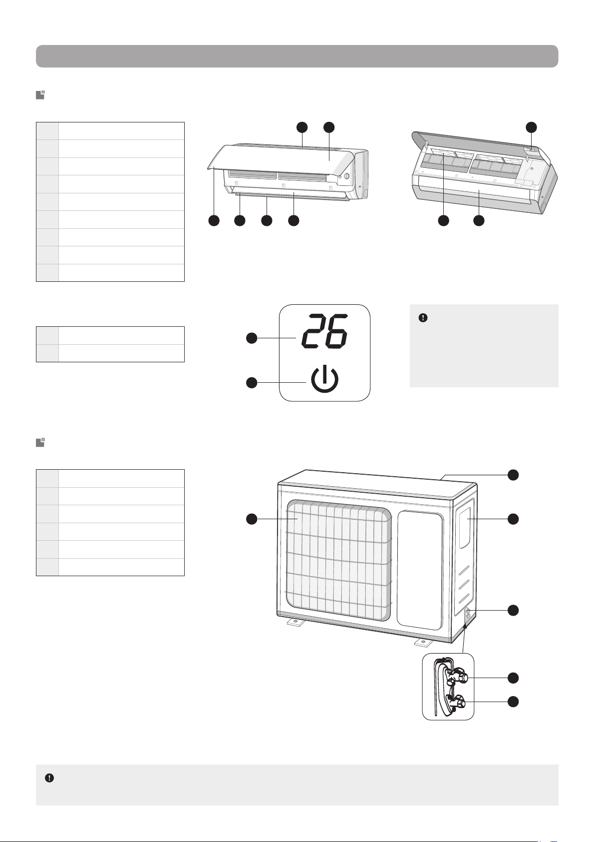
INDOOR UNIT
OUTDOOR UNIT
Front Panel Display
1 Front panel
2 Upper airow deector
3 Lower airow deector
4 Air outlet
5 Air inlet
6 Display (see below)
7 Dust lter
8 Directional louvers (inside)
9 Emergency button
11 Temperature indicator
12 Power indicator
1 2 7 83 4
6 95
11
12
13 Air inlet
14 Air outlet
15 Wiring cover
16 Valve cover
17 Gas valve
18 Liquid valve
14 15
16
17
18
13
NOTE : The above illustrations are only intended to be simplied representations of the appliance and
may not reect the exact appearance of the product purchased.
NOTE : The content of
the display and the colours
and shapes of the indica
-
tors may vary. Please refer
to the actual display.
8
OPERATION GUIDE
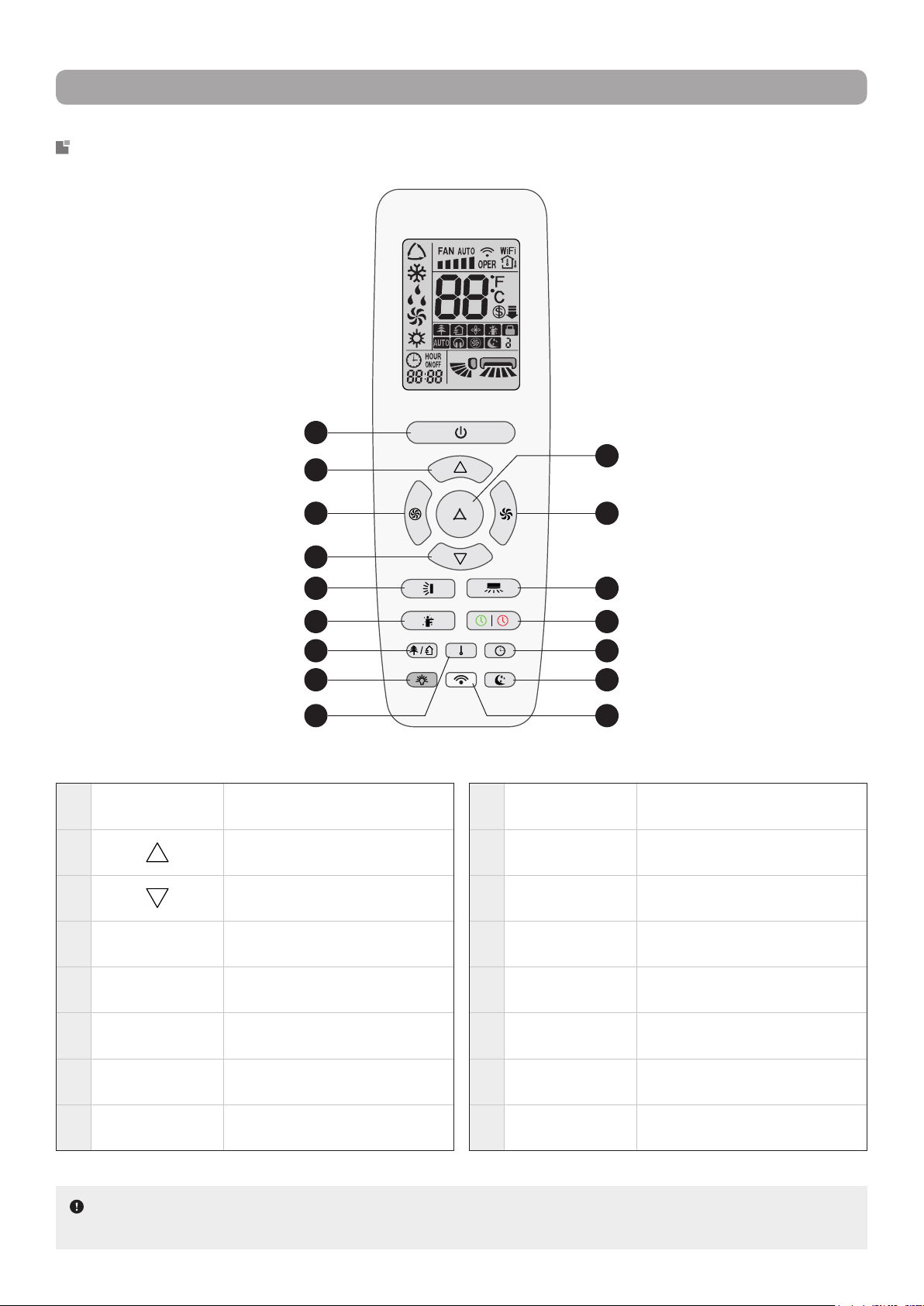
REMOTE CONTROL BUTTONS
1
POWER Turns the unit ON or OFF
2
Increases temperature or timer
delay
3
Decreases temperature or timer
delay
4
TURBO
Activates or desactivates Turbo
mode
5
MODE
Allows to select an operation
modes
6
FAN
Allows to select a ventilation
speed
7
VERTICAL
SWING
Adjusts vertical swing angle
8
HORIZONTAL
SWING
Adjusts horizontal swing angle
9
I FEEL
Activates or desactivates
I Feel function
10
TIMER-ON /
TIMER-OFF
Allows to set a switch-on or
switch-on timer
11
HEALTH /
SCAVENGING
Activates or desactivates Heath
and/or Scavenging modes
12
LIGHT
Activates or desactivates indoor
unit display
13
CLOCK Allows to set the system clock
14
TEMP
Allows to set the temperature
display type
15
SLEEP
Allows to select a Sleep mode
option
16
WIFI
Activates or desactivates WiFi
function
1
2
4 6
8
10
1311
1512
14 16
5
3
7
9
NOTE : Buttons and indicators may differ from model to model, but their functionality remains the
same. Some functions may not be available on all models.
9
OPERATION GUIDE
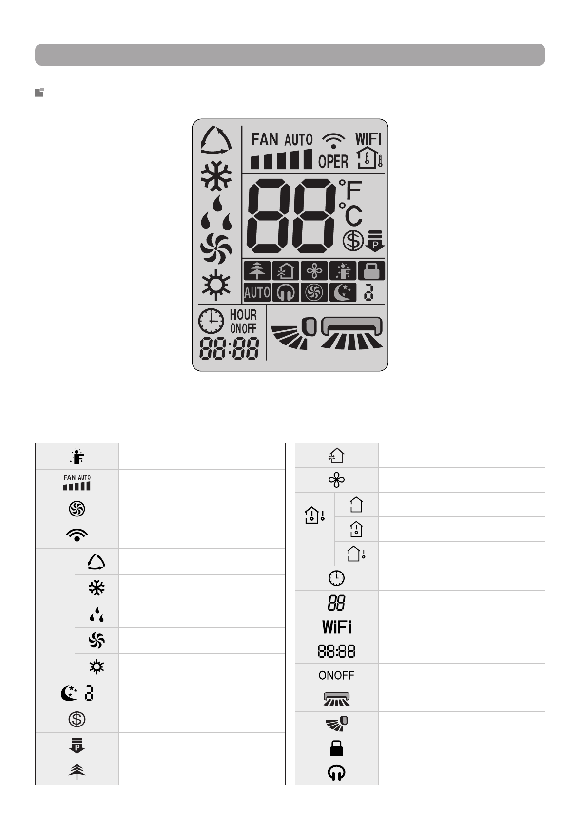
REMOTE CONTROL DISPLAY SCREEN INDICATORS
Scavenging mode
X-Fan function
Temp.
display
type
Set temperature
Indoor ambient temperature
Outdoor ambient temperature
Clock
Temperature display
WiFi function
Time display
Timer-ON / Timer-OFF
Horizontal swing angle
Vertical swing angle
Control lock function
Quiet mode
I Feel function
Set fan speed
Turbo mode
Sending signal
Operation Modes
Auto mode
Cooling mode
Drying mode
Ventilation mode
Heating mode
Sleep mode
8 °C Heating function
Power Limit mode
Health mode
10
OPERATION GUIDE
BASIC OPERATING INSTRUCTIONS
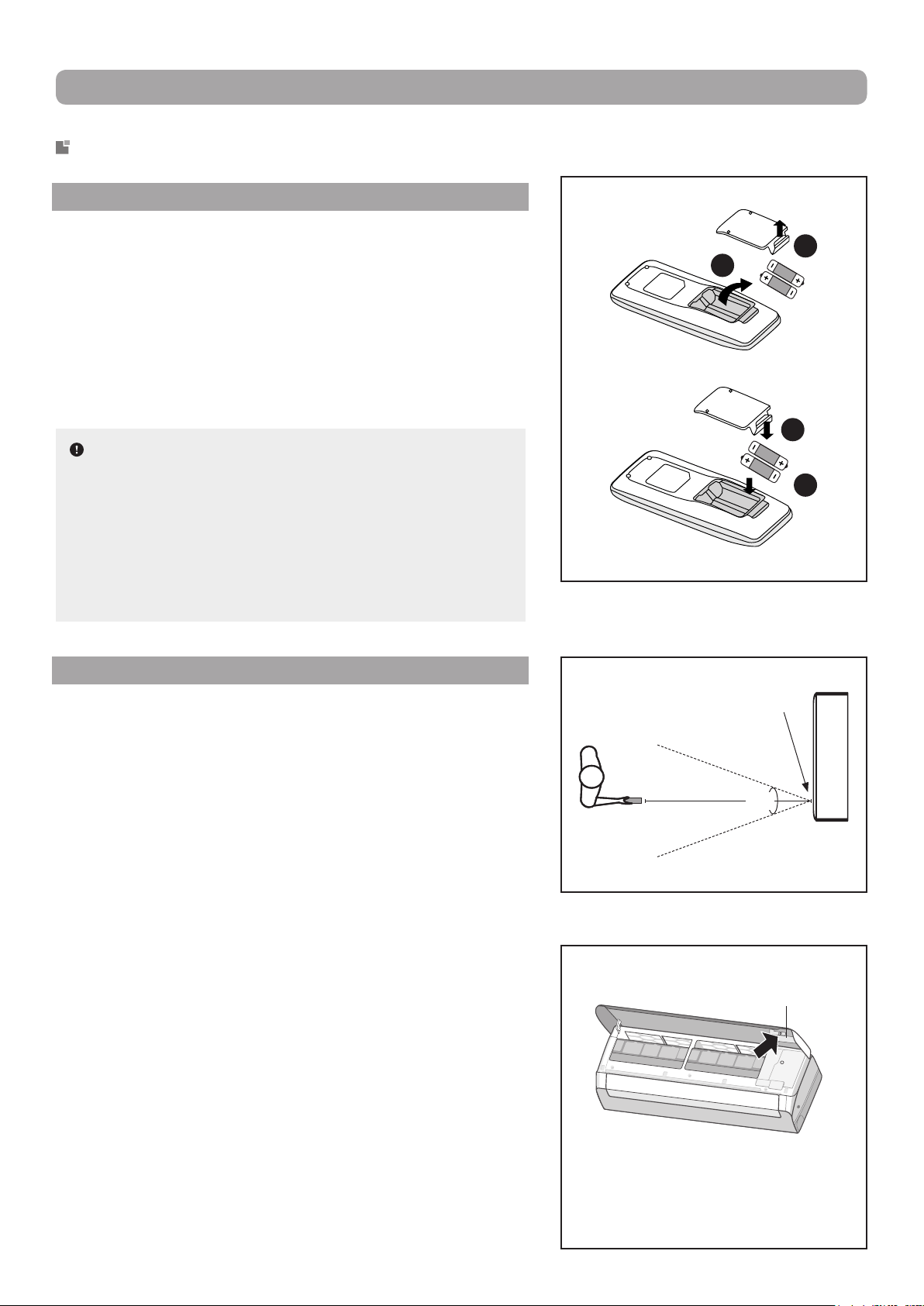
BATTERY REPLACEMENT
1. Remove the battery compartment cover from the back of
the remote control by lifting it in the direction of the arrow.
2. Take out the depleted batteries.
3. Insert two new 7# AAA (1.5 V) dry batteries, making sure to
match the polarity markings (+ and –) shown on the remote
control.
4. Replace the compartement cover by sliding it into place.
NOTES :
▪ Do not use rechargeable batteries.
▪ Replace with new batteries of the same brand when re
-
placement is required.
▪ Do not dispose of used batteries with other domestic
waste. Separate collection of such waste for special
treatment is necessary.
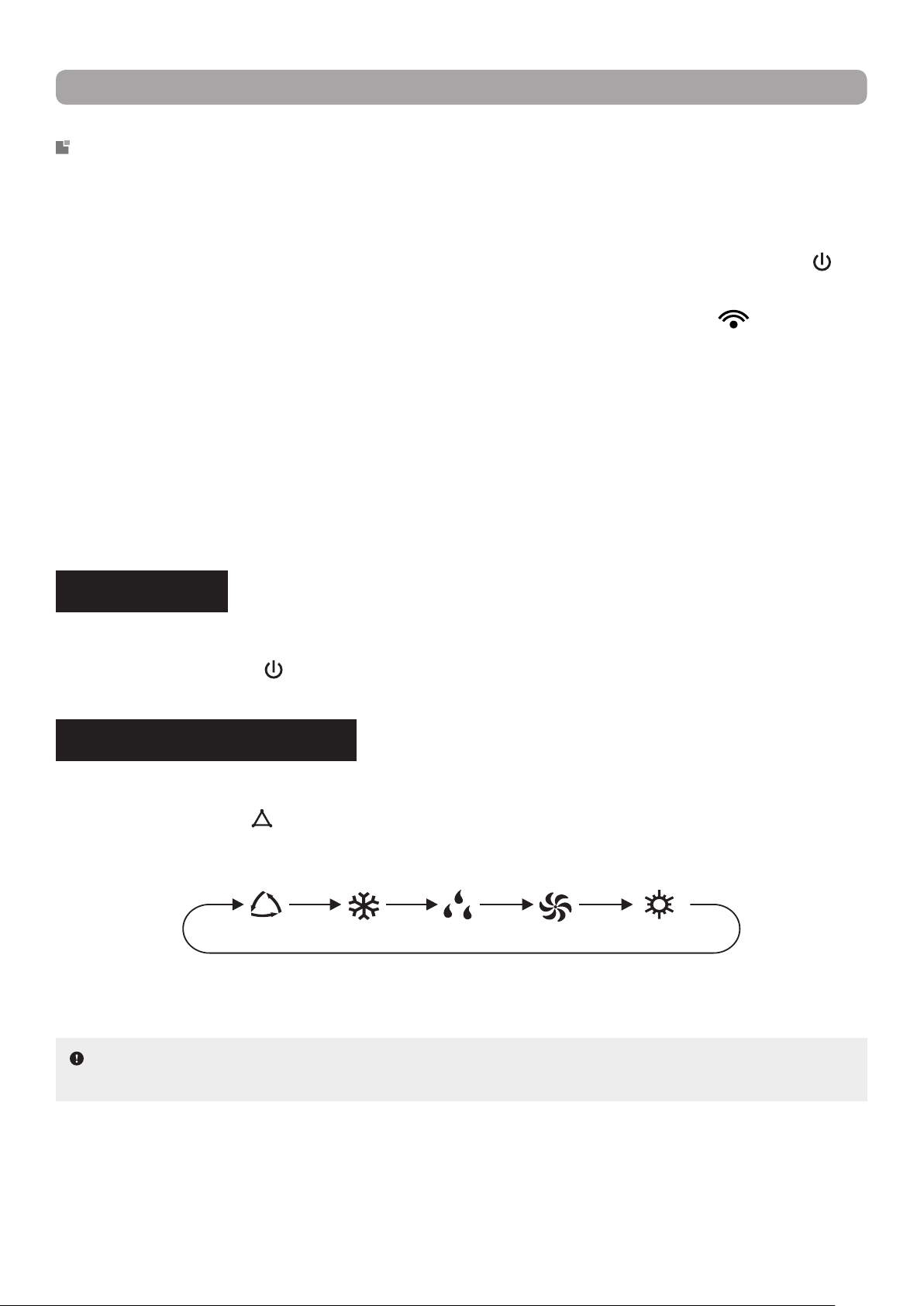
USAGE RECOMMENDATIONS
▪ Direct the remote control toward the signal receiver of the
indoor unit for optimal use.
▪ In order for the signal to be transmitted successfully, the dis
-
tance between the remote control and the indoor unit must
be less than 8 meters (26 feet) and within a 60° angle.
▪ Make sure that there are no objects between the remote con
-
trol and the signal receiver of the indoor unit that could block
the signal.
▪ Never leave the remote control exposed to the sun.
▪ Keep the remote control at a distance greater than 1 meter (3
feet) from appliances or devices such as televisions, uores
-
cent lamps, wireless phones or other electrical appliances to
avoid signal interference.
▪ When not using the remote control for an extended period of
time, please remove the batteries so as not to wear them out
needlessly.
▪ A blurry or blank display screen on the remote control may
indicate a low battery level. In such a case, replace the bat
-
teries with new ones.
▪ If the remote control is lost or damaged, use the emergency
button to turn the indoor unit on or off.
1
2
4
3
Indoor unit
signal receiver
8 m (26 ft)
60°
Emergency
button
Open the front panel and press the
emergency button on the inside of
the panel to turn on the unit. When
turned on, the unit operates in Auto
mode.
11
OPERATION GUIDE
FUNCTION DESCRIPTION AND SETTING
▪ This remote control is for general use. It can be used for multi-function heat pumps and air conditioners.
For the functions that the model does not have, if you press the corresponding button on the remote con
-
trol, the unit will keep its initial operating status.
▪ Immediately after the power is turned on, the indoor unit will make a beep and the power indicator "
" will
light up on the indoor unit display. After this point, you can operate the heat pump using the remote control.
▪ In operating state, when a button on the remote control is pressed, the signal symbol "
" on the display
screen of the remote control will blink once and the indoor unit will emit a beep. This indicates the signal
has been successfully received by the unit.
▪ Models with WiFi control or a wired thermostat must rst be controlled by a standard remote in Auto
mode. Following this, the setting of the temperature can be made via the WiFi mobile App or the wired
thermostat.
▪ This remote control can set the temperature in Auto mode. When used with a unit that does not have the
Auto mode temperature setting function, the temperature set in this mode will be invalid, or the set tem
-
perature displayed on the unit will not be the same as that on the remote control.
POWER ON/OFF
Allows the user to power the unit on or off.
Press the POWER button (
) to turn on the unit. Press again to turn off the unit.
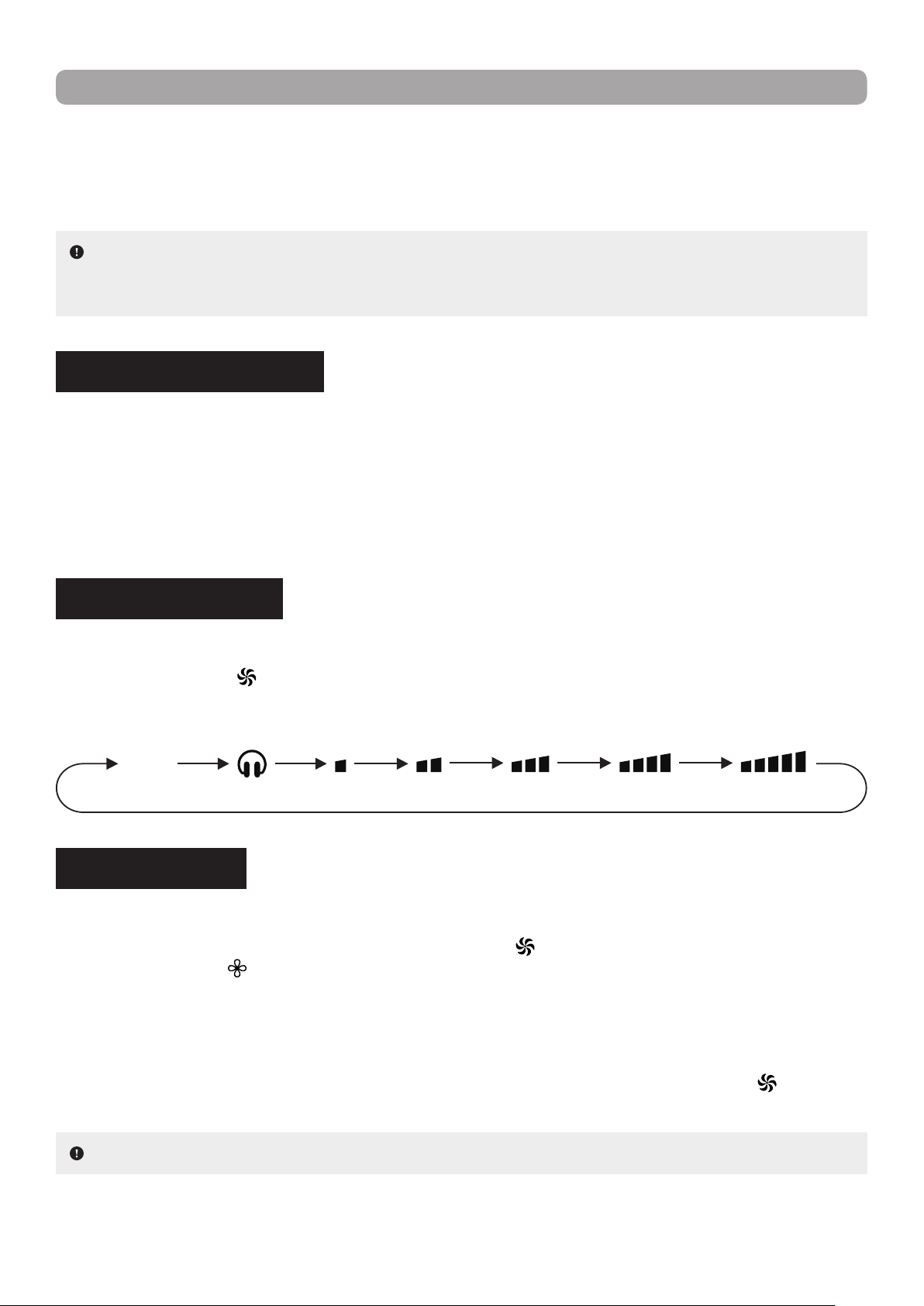
OPERATION MODE SETTING
Allows the user to select an operation mode in accordance with their needs.
Press the MODE button (
) on the remote control to select the desired operation mode. With each press
of the button, the setting options cycle through in the following order :
Auto Mode : In this operation mode, the unit will automatically use the best presets based on the ambient
room temperature.
Cooling Mode : In this operation mode, the unit will cool the room to the desired temperature as well as
remove moisture from the air.
Drying Mode : In this operation mode, the unit will reduce the humidity in the air to make the room more
comfortable. Fan speed is automatically set to Low speed and cannot be adjusted.
NOTE : Under this mode, the temperature can be displayed on the indoor unit and the set temperature
can be adjusted. Use the arrow buttons (▲ or ▼) to adjust the temperature to the desired setting.
Auto Cooling Drying Ventilation Heating
12
OPERATION GUIDE
Ventilation Mode : In this operation mode, the unit will blow uncooled/unheated air. Set temperature cannot
be adjusted.
Heating Mode : In this operation mode, the unit will heat the room to the desired temperature.
TEMPERATURE SETTING
Allows the user to set the temperature in accordance with their needs.
Use the arrow buttons (▲ or ▼) to increase or decrease the set temperature. Each press of either button
increases or decreases the value by 1 °C (or 1 °F) to a maximum of 30 °C (or 86 °F) and to a minimum of
16 °C (or 61 °F). Holding either button down for more than 2 seconds will cause the degrees to scroll up or
down more quickly. Once the temperature setting is complete, the temperature indicator on the indoor unit
will adjust to reect the change.
NOTE : To prevent cold air from being blown into the room as Heating mode is started, the indoor
unit will delay blowing air for 1 to 5 minutes in order to preheat the air (the actual delay time depends on
indoor ambient temperature).
X-FAN FUNCTION
Allows the fan of the indoor unit will blow air to eliminate moisture on the evaporator to avoid mould formation.
While in Cooling or Drying mode, hold down the FAN button (
) for at least 2 seconds to activate the X-Fan
function. The symbol "
" will appear on the display screen of the remote control.
If the unit is powered down while X-Fan is still running, the indoor fan will continue operation for a few
minutes in order to dry the inside of the indoor unit. Powering up the unit during this time will automatically
deactivate the function.
If the unit has been left running with the X-Fan function activated, hold down the FAN button (
) for at least
2 seconds to deactivate it.
NOTE : This function is not available in Auto, Ventilation or Heating mode.
FAN SPEED SETTING
Allows the user to select a fan speed in accordance with their needs.
Press the FAN button (
) on the remote control to select the desired fan speed. With each press of the
button, the setting options cycle through in the following order :
AUTO
Quiet Mode Low Low/Med Med/HighMedium High
13
OPERATION GUIDE
TURBO MODE
Allows the indoor unit to run at super-high fan speed to cool or heat so that the ambient temperature reaches
the set temperature much quicker.
While Cooling or Heating mode, press the TURBO button (
) in the remote control to activate the function.
The symbol "
" will appear on the display screen of the remote control. Pressing the button again will
deactivate the Turbo function.
HORIZONTAL SWING SETTING
Allows the user to adjust the louvers of the indoor unit to a xed angle in accordance with their needs.
Press the HORIZONTAL SWING button (
) on the remote control to select the desired xed angle. By
pressing the button in rapid succession of less than 2 seconds, the setting options cycle through in the fol
-
lowing order :
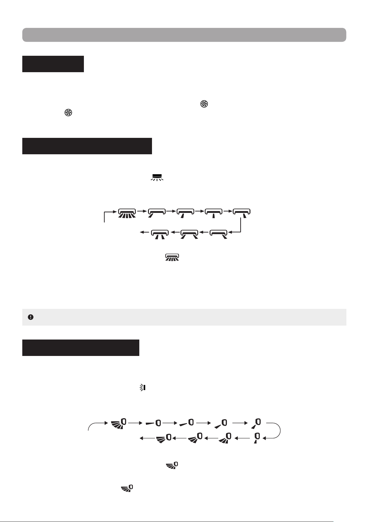
VERTICAL SWING SETTING
Allows the user to adjust the airow deectors of the indoor unit to a xed angle or to continuously swing in
accordance with their needs.
Press the VERTICAL SWING button (
) on the remote control to select the desired xed or sliding angle.
By pressing the button in rapid succession of less than 2 seconds, the setting options cycle through in the
following order :
NOTE : Some angle options are only available for certain models.
When the parameter switches from " OFF " to "
", if you delay pressing the button for more than 2 sec-
onds, the parameter will automatically revert to the " OFF " state.
Holding the button down continuously for more than 2 seconds will cause the airow deectors and louvers
to automatically swing back and forth, and sides to sides. When the button is released, the unit stops swing
-
ing at the current angle, providing the user with a personalized xed angle.
When the parameter switches from " OFF " to "
", if you delay pressing the button for more than 2 sec-
onds, the parameter will automatically revert to the " OFF " state.
When selecting the parameter "
", the airow deectors will continuously swing up and down at maxi-
mum angle.
OFF / no display
(deectors stop at
current position)
OFF / no display
(louvers stop at
current position)
14
NOTE : Some angle options are only available for certain models.
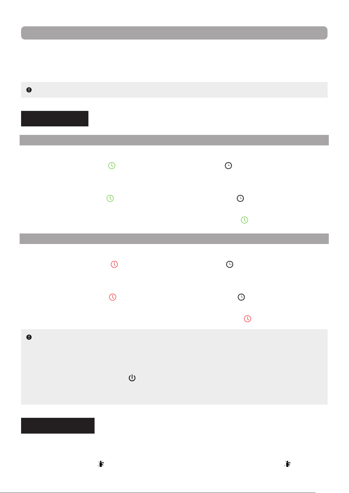
NOTES :
▪ A switch-on and switch-off timer can be active concurrently.
▪ Before setting a timer, ensure that the system clock has been set to current time.
▪ Once the clock is set, the heat pump will turn on or off when the delay elapsed. When the unit is under a
timer setting, the POWER button (
) will have no effect on operation. If the timer is no longer needed,
use the remote control to cancel it.
▪ During timer setting, if no operation is performed for 5 seconds, the setting is canceled.
TIMER SETTING
SWITCH-ON TIMER
Allows the user to set a switch-on timer. The unit will switch on once the start delay has been reached.
Press the TIMER-ON button (
) on the remote control. The symbol " " on the display screen of the re-
mote control will disappear and the word " ON " will start blinkling. Use the arrow buttons (▲ or ▼) to set the
desired time. Each press of either button increases or decreases the time by 1 minute. Holding either button
down for more than 2 seconds will cause the minutes to scroll up or down more quickly. Once completed,
press the TIMER-ON button (
) to conrm the timer setting. The symbol " " will reappear on the display
screen and the word " ON " will stop blinking.
To cancel a switch-on timer that has been set, press the TIMER-ON button (
) on the remote control.
SWITCH-OFF TIMER
Allows the user to set a switch-off timer. The unit will stop running when the set operating time has elapsed.
Press the TIMER-OFF button (
) on the remote control. The symbol " " on the display screen of the re-
mote control will disappear and the word " OFF " will start blinkling. Use the arrow buttons (▲ or ▼) to set the
desired time. Each press of either button increases or decreases the time by 1 minute. Holding either button
down for more than 2 seconds will cause the minutes to scroll up or down more quickly. Once completed,
press the TIMER-OFF button (
) to conrm the timer setting. The symbol " " will reappear on the display
screen and the word " OFF " will stop blinking.
To cancel a switch-off timer that has been set, press the TIMER-OFF button (
) on the remote control.
I FEEL FUNCTION
Allows the user to use the remote control as the primary temperature sensor in order for the indoor unit to
provide better comfort based on the location of the user and remote control.
Press the I FEEL button (
) on the remote control to activate the function. The symbol " " will appear
OPERATION GUIDE
Holding the button down continuously for more than 2 seconds will cause the airow deectors and louvers
to automatically swing back and forth, and sides to sides. When the button is released, the unit stops swing
-
ing at the current angle, providing the user with a personalized xed angle.
15
NOTES :
▪ Clock time adopts the 24-hour time format.
▪ If no operation is performed for 5 seconds, the setting is canceled.
on the display screen of the remote control. Once activated, the remote control will transmit the ambient
temperature measured at its location to the indoor unit and the unit will automatically adjust its operation
in accordance to the transmitted temperature. Pressing the button again will deactivate the I Feel function.
Once activated, the user should keep the remote control in close proximity for the function to be effective.
The remote control should also be kept within an area where the indoor unit can receive its signal. Do not
place the remote control near high temperature appliances or devices to avoid measuring an inaccurate
ambient temperature.
CLOCK SETTING
Allows the user to set the system clock to current time.
Press the CLOCK button (
) on the remote control to set the time. The symbol " " will start blinking on
the display screen of the remote control. Use the arrow buttons (▲ or ▼) to set the time. Each press of
either button increases or decreases the time by 1 minute. Holding either button down for more than 2 sec
-
onds will cause the minutes to scroll up or down more quickly. Once the clock setting is complete, press the
CLOCK button (
) to conrm. The symbol " " will stop blinking.
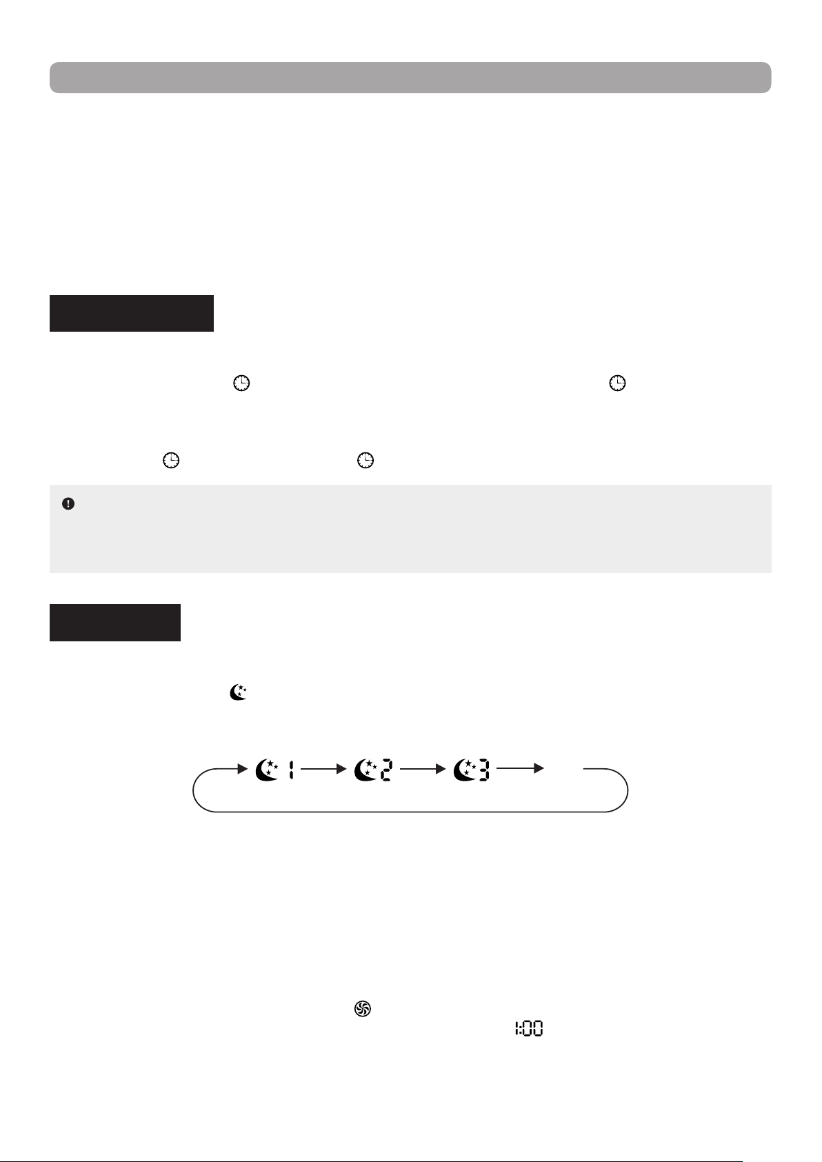
SLEEP MODE
Allows the user to select a preset sleep curve or create a customized one in accordance with their needs.
Press the SLEEP button (
) on the remote control to select the desired sleep curve. With each press of
the button, the setting options cycle through in the following order :
Sleep 2Sleep 1 Sleep 3
OFF
(no display)
Sleep 1 : In Cooling mode, one hour after the mode is set, the temperature increases by 1 °C. After two
hours, the temperature increases by another 2 °C. The unit then holds this temperature.
In Heating mode, one hour after the mode is set, the temperature decreases by 1 °C. After two
hours, the temperature decreases by another 2 °C. The unit then holds this temperature.
Sleep 2 : In this mode, the unit operates according to a group of sleep temperature curve presets.
Sleep 3 : In this mode, the user can create their own custom sleep curve by following the procedure below.
1. Hold down the TURBO button (
) for some time until the remote control enters user custom-
ization status. The remote control time display will show " " and the temperature display will
show the corresponding temperature of the last sleep curve setting and will blink (on the very rst
input, the displayed temperature will be in accordance with the factory’s initial curve setting).
2. Use the arrow buttons (▲ or ▼) if you wish to change the corresponding temperature setting.
OPERATION GUIDE
16
Once completed, press the TURBO button ( ) to conrm the setting.
3. Following conrmation, the time displayed on the remote control screen will automatically
increase by 1 hour (going from "
" to " ", then " ", and so on up to " ") and the
temperature display will blink, as previously.
4. Repeat the above steps 2 and 3 until the temperature is set for all 8 hours of the sleep curve.
Once the sleep curve setting is completed, the time and temperature display on the remote con
-
trol will return to its original display.
The user can view or revise a custom sleep curve. Hold down the TURBO button (
) for
some time until the remote control enters user customization status. To view the setting without
change, simply press the TURBO button (
) to move on to the next setting. If a setting needs
to be adjusted, Use the arrow buttons(▲ or ▼) to do so then pressa the TURBO button (
) to
conrm the new setting.
OPERATION GUIDE
WIFI FUNCTION
Allows the user to control the unit remotely from their smartphone or tablet using the GREE+ App.
Press the WIFI button (
) on the remote control to activate the function. The word “ WiFi ” will appear on
the display screen of the remote control. Holding down the WIFI button (
) for at least 5 seconds will
deactivate the WiFi function.
Holding down the MODE
( )
and WIFI ( ) buttons simultaneously for 1 second will restore the WiFi
module to factory settings.
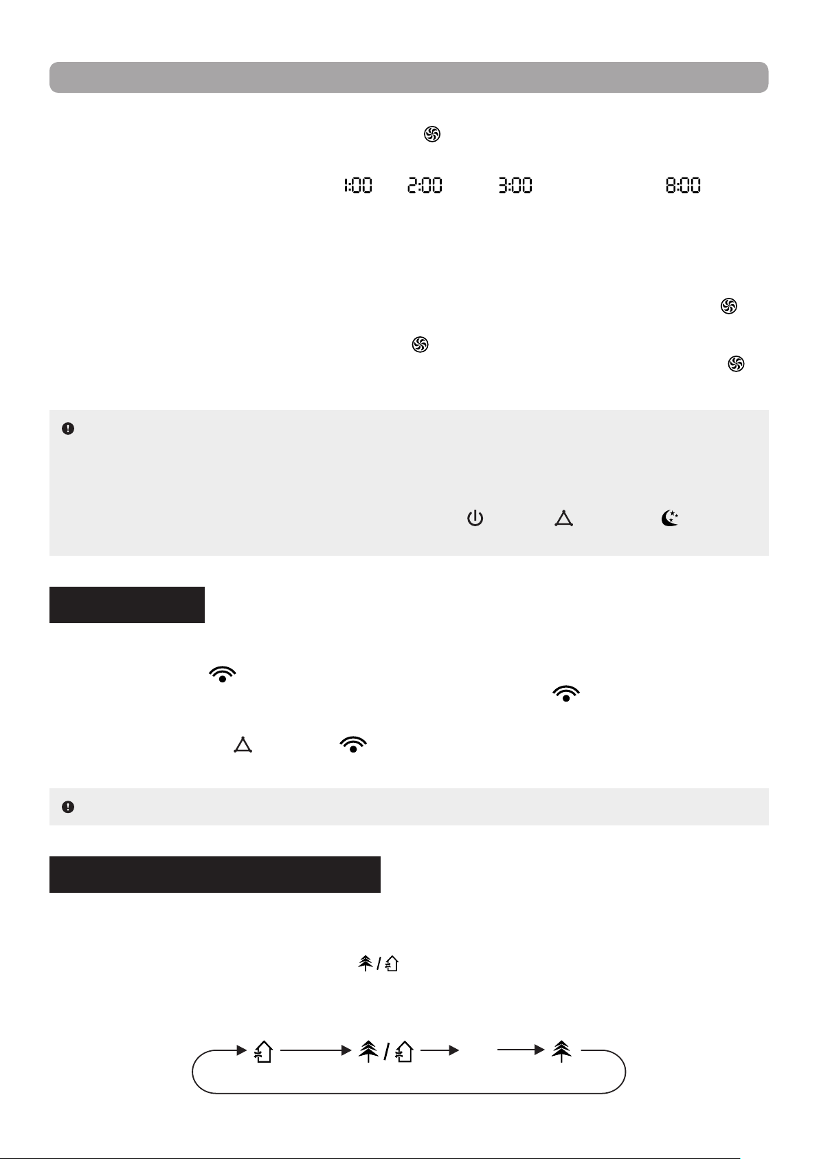
HEATLH AND SCAVENGING MODES
Allows the unit to clean the air by removing dust particles and germs and/or to gradually replace stale air
inside the room with fresh outside air.
Press the HEALTH / SCAVENGING button (
) on the remote control to select the desired mode(s).
With each press of the button, the setting options cycle through in the following order :
Scavenging
& Heath modes
Scavenging
mode only
Health
mode only
OFF
(no display)
NOTE : This function is only available for some models.
NOTES :
▪ While setting a custom sleep curve, if no operation is performed for more than 10 seconds, the process
will be automatically cancelled and the time and temperature display on the remote control will return
to its original display.
▪ While setting a custom sleep curve, pressing the POWER (
), MODE
( )
or SLEEP
( )
button will
automatically cancel the process.
17
OPERATION GUIDE
INDOOR UNIT DISPLAY SETTING
Allows the indoor unit to display of the temperature and power indicators on its front panel.
Press the LIGHT button (
) on the remote control to turn on the display of the indoor unit’s front panel.
Press the button again to turn off the display.
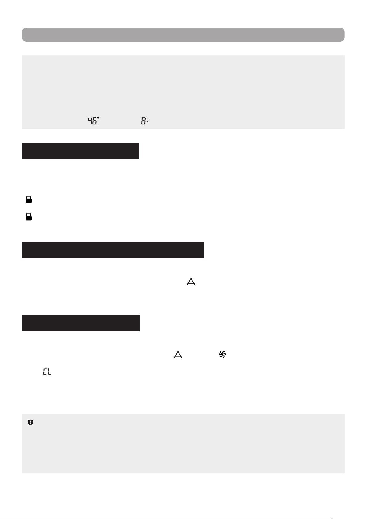
TEMPERATURE DISPLAY SETTING
Allows the user to select the type of temperature displayed on the indoor unit’s front panel.
Press the TEMP button (
) on the remote control to set the temperature type to set temperature. The sym-
bol " " (or no display, depending on model) will appear on the display screen of the remote control. Press
the button again to set the temperature type to indoor ambient temperature. The symbol "
" will appear on
the display screen.
ENERGY-SAVING FUNCTION
Allows the indoor unit to automatically adjust the set temperature based on factory setting to achieve the
best energy saving performance.
While in Cooling mode, press the TEMP (
) and CLOCK ( ) buttons simultaneously on the remote con-
trol to activate the function. The temperature display of the remote control will show " ". Press the same
buttons simultaneously again to deactivate the Energy-Saving function.
NOTES :
▪ When Energy-Saving is active, the set temperature cannot be adjusted and the fan speed is auto
-
matically set to Auto speed and cannot be changed. Pressing the TURBO button
( )
will result in no
signal being sent.
▪ The Sleep and Energy-Saving functions cannot operate concurrently. If Energy-Saving has been pre
-
viously set, activating Sleep mode will automatically cancel the Energy-Saving function. Conversely, if
a Sleep mode has been previously set, activating the Energy-Saving function will automatically cancel
the Sleep function.
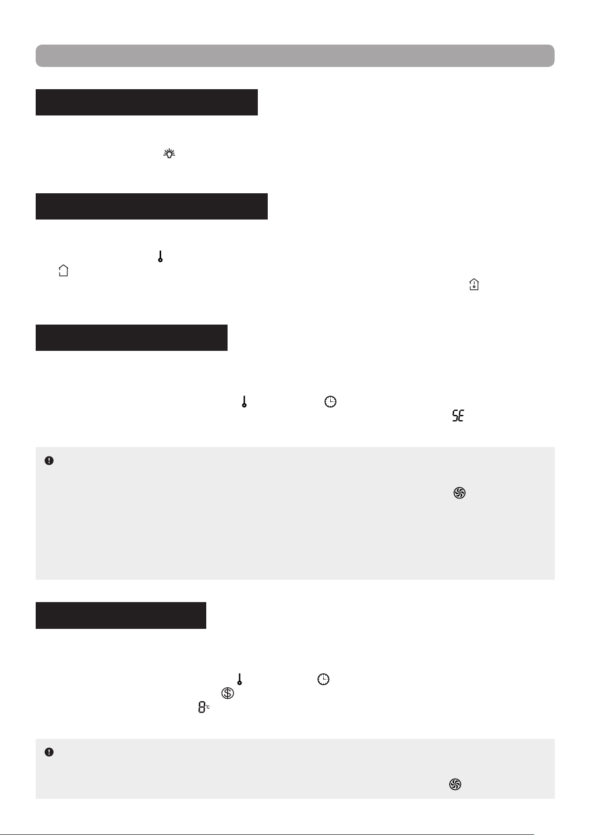
8 °C HEATING FUNCTION
Allows the indoor unit to automatically start heating operation to maintain an indoor ambient temperature of
8 °C (46 °F) to prevent property damage when the user is absent for an extended period of time.
While in Heating mode, press the TEMP (
) and CLOCK ( ) buttons simultaneously on the remote control
to activate the function. The symbol "
" will appear on the display screen of the remote control and the
temperature indicator will show "
". Press the same buttons simultaneously again to deactivate the 8 °C
Heating function.
NOTES :
▪ When 8 °C Heating is active, the set temperature cannot be adjusted and the fan speed is automat
-
ically set to Auto speed and cannot be changed. Pressing the TURBO button
( )
will result in no
18
OPERATION GUIDE
CONTROL LOCK FUNCTION
Allows the user to lock the remote control buttons to prevent a young child or others from changing the
settings.
Press the arrow buttons (▲ or ▼) simultaneously on the remote control to activate the function. The symbol
" "
will appear on the display screen of the remote control. Once activated, the buttons of the remote con-
trol will become inoperative. Attempting to use the controls while the remote is locked will cause the symbol
" "
to blink three times on the display screen and no signal will be sent to the unit. Press the same buttons
simultaneously again to deactivate the Control Lock function.
SELF-CLEANING FUNCTION
Allows the indoor unit to clean itself, removing the accumulated dirt and bacteria from the evaporator.
While the unit is turned off, hold down the MODE (
) and FAN ( ) buttons simultaneously on the remote
control for at least 5 seconds to activate the function. The temperature display of the remote control will
show "
". Hold down the same buttons again for at least 5 seconds to cancel the Self-Cleaning function.
During the self-cleaning process, the unit will alternate between fast cooling and fast heating. This may cre
-
ate sounds of thermal expansion or shrinkage, or of owing liquid. The unit may also blow cool or warm air,
which is a normal phenomenon. Once the cleaning process is complete, the unit will go into standby mode.
TEMPERATURE MEASURING UNIT SETTING
Allows the user to select between Celsius or Fahrenheit as the temperature measuring unit for the display.
While the unit is turned off, press the MODE button (
) and arrow button
"▼"
simultaneously to select
Celsius as the desired temperature measuring unit for the display. Press the same buttons simultaneously
again to select Fahrenheit.
signal being sent.
▪ The Sleep and 8 °C Heating functions cannot operate concurrently. If 8 °C Heating has been previously
activated, activating Sleep mode will automatically cancel the 8 °C Heating function. Conversely, if a
Sleep mode has been previously set, activating the 8 °C Heating function will automatically cancel the
Sleep function.
▪ If the temperature measuring unit has been set to Fahrenheit, the temperature indicator of the remote
control will show "
" instead of " ".
NOTES :
▪ During cleaning process, make sure the room is well ventilated so as not to affect the level of comfort.
▪ The Self-Cleaning function can only work under normal ambient temperature. If the unit is located in a
dusty environment, run this function once a month; if it is not, every three months is sufcient.
▪ This function is only available for some models.
19
OPERATION GUIDE
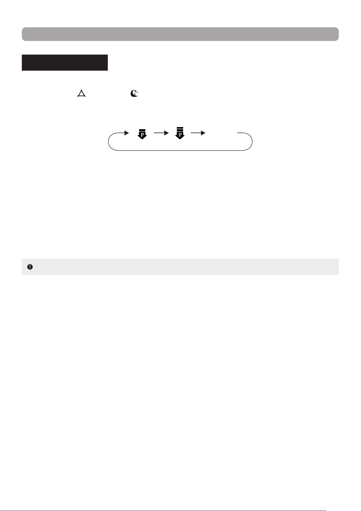
POWER LIMIT MODE
Allows the system to limit the maximum output power.
Press the MODE
( )
and SLEEP
( )
buttons simultaneously on the remote control to select the desired
Power Limit mode. With each press of the buttons, the setting options cycle through in the following order :
The maximum power limit of the Power Limit 2 setting is lower than that of the Power Limit 1 setting.
If the remote control is turned off or the battery are removed while Power Limit is active, the function will be
automatically cancelled. Reactivate the function to resume the power limiting operation.
If the current power is lower than the maximum power of the Power Limit 2 setting, then the power will not
be limited after entering this mode.
For an installation with one outdoor unit and two indoor units, if any one of the indoor unit enters into Power
Limit function, the outdoor unit will enter into the set limiting power mode of that indoor unit. If the two indoor
units enter into Power Limit function, then the power of outdoor unit will be limited in accordance with the
lower power of the two indoor units.
NOTE : This function is only available for some models.
OFF
(no display)
Power
Limit 1
Power
Limit 2
20
MAINTENANCE
WARNING :
▪ Turn off the unit and unplug the power supply before cleaning to avoid electric shock.
▪ Do not wash the indoor unit with water to avoid electric shock.
▪ Do not use volatile liquid to clean the indoor unit.
▪ Do not use liquid or corrosive detergent to clean the indoor unit and do not splash water or other liquid
on the unit, otherwise it may damage the plastic components or even cause electric shock.
NOTE : Do not remove the front panel when cleaning it.
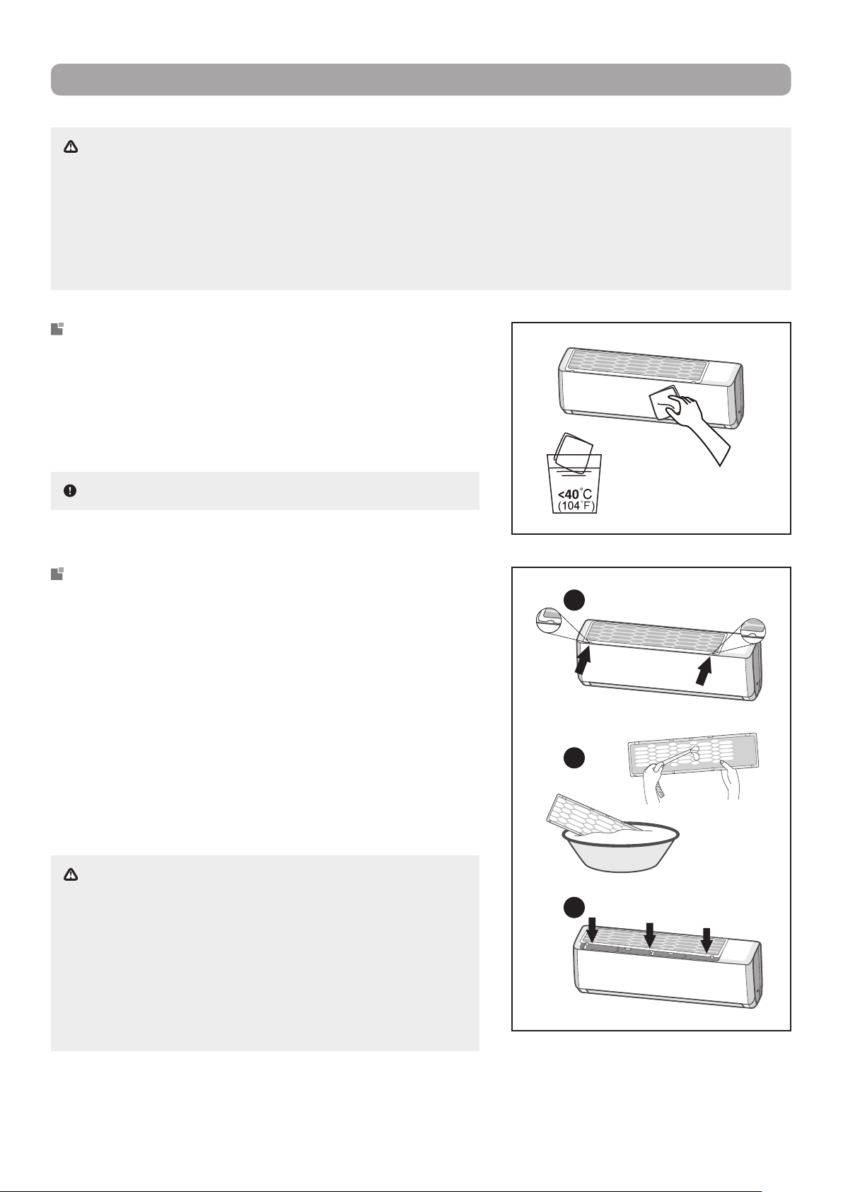
CLEANING THE SURFACE
Gently wipe the surface of the indoor unit with a dry cloth or
one moistened with warm water.
If using a damp cloth, use water no warmer than 40 °C (104 °F).
Try to clean the unit frequently to keep it in good condition.
WARNING :
▪
The lter should be cleaned every three months. If there
is a lot of dust in the operating environment of the indoor
unit, lter cleaning should be more frequent.
▪ When
removing the dust lter, avoid touching the ns to
prevent injury.
▪ Do not use an open ame or hair dryer to dry the dust
lter to avoid deformation and re hazard.
CLEANING THE DUST FILTER
1. To remove the lter, rst press the spring fasteners at both
ends in the direction indicated by the arrows
in the illustra-
tion
, then release the lter from the clamps. Pull the lter for-
ward and remove it.
2. Use clean water to wash the dust lter or a vacuum to col-
lect the dust. If the lter is very dirty (e.g. grease), use warm
water (45 °C) with a neutral detergent to clean it. Put the
lter in a shaded location to dry it.
3. After cleaning, reinstall the lter by sliding it along the guide
rails on both sides, then press the edges of the lter to snap
it into place, as indicated by the arrows in the illustration.
1
2
3

21
MAINTENANCE
PRE AND POST SEASON MAINTENANCE
PRE-SEASON
1. Clean the indoor unit and the dust lter.
2. Check for obstructions at the air inlet and outlet of the indoor and outdoor units.
3. Check that the drain pipe is not blocked or damaged.
4. Check if the mounting bracket of the outdoor unit is damaged or corroded. If so, please contact your
dealer.
5. Insert batteries in the remote control and check that the unit is working properly.
POST-SEASON
1. Disconnect the power supply of the heat pump.
2. Clean the indoor unit and the dust lter.
3. Check if the mounting bracket of the outdoor unit is damaged or corroded. If so, please contact your
dealer.
4. Remove the batteries from the remote control.
RECYCLING AND DISPOSAL
Many of the packaging materials in this product are recyclable. Please dispose of them with the recyclable
waste collected by your municipality.
Unwanted electrical equipment and used batteries should not be treated as domestic waste because the
items may pose environmental hazards. Electronic and electrical equipments cab contain toxic substances
which can produce toxic air pollutants and contaminate soil. If you wish to dispose of your equipment,
please contact your local dealer, service center or local authority for the proper disposal method.
22
TROUBLESHOOTING
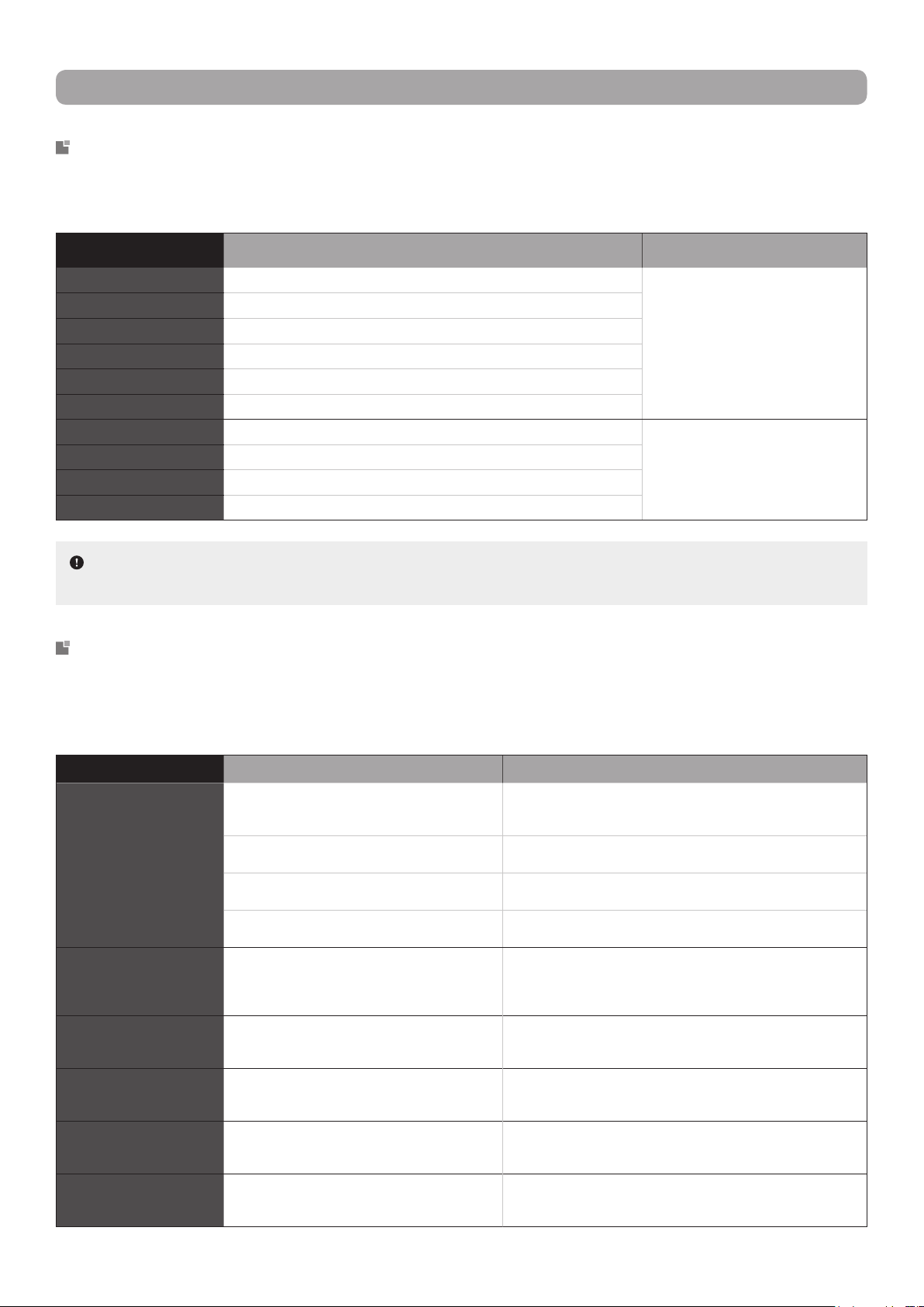
ERROR CODE DESCRIPTION SOLUTION
E1 System high pressure protection These errors can be normally cleared
by restarting the unit. If it does not,
please contact your local dealer or
service center to obtain assistance.
E5 Over-current protection
E6 Indoor and outdoor units communication error
E8 System high temperature protection
H3 Compressor overheat protection
H6 Fan motor malfunction
C5 Jumper cap malfunction These errors require the expertise of
qualied technicians in order to be
resolved. Please contact your local
dealer or service center.
F0 Refrigerant shortage or blockage protection
F1 Indoor ambient temperature sensor open or short-circuited
F2 Evaporator temperature sensor open or short-circuited
SITUATION POSSIBLE CAUSES SOLUTIONS
The indoor unit does not
appear to be operating.
There may have been a power outage. If there is a power outage and the electricity is not yet restored,
wait for the power to be restored. When it is, the unit may need
to be restarted.
The power cord plug may have become loose
from the outlet.
Firmly push the plug into the power outlet.
A circuit breaker may have been tripped or a
fuse may have blown.
Replace the fuse or reset the circuit breaker. Make sure that
there are no other appliances on the same circuit.
There may be an active switch-on timer cur-
rently preventing operation.
If the timer setting was not intended, cancel it using the remote
control, otherwise wait until the unit starts at the set time.
The compressor
does not appear to be
operating.
The unit may have been immediately restarted
after having being shut off, or the operation
mode may have been recently changed.
When changing operation modes or when immediately turning
on the unit after having turned it off, a 3-minute protection delay
is be triggered to protect the compressor. Wait until the delay
has elapsed.
The indoor unit
appears to be operating
abnormally.
There may be interference in the room from a
television, uorescent lamp, a wireless device,
etc.
Disconnect and reconnect the power to the unit, then restart
the appliance.
The indoor unit emits
undesirable odours.
Odours may be caught by the indoor or outdoor
unit and blown into the room with the air, or the
dust lter may be dirty.
Remove any source of odours in the vicinity of both the indoor
or outdoor units. Check and clean the dust lter if necessary.
The indoor unit emits
cracking sounds.
The indoor unit may have been recently turned
on or off.
This is a normal phenomenon. The plastic components of the
indoor unit are subject to thermal expansion and contraction
caused by temperature changes. No action is required.
The indoor unit emits a
sound of owing liquid.
The indoor unit may have been recently turned
on or off.
This is a normal phenomenon. The refrigerant inside the indoor
unit is moving due to operation starting which produces the
sound of owing liquid. No action is required.
ERROR CODES IDENTIFICATION
If the heat pump has a faulty component, the temperature indicator on the indoor unit will ash an error
code. Please refer to the list below to identify the error code and to solve the issue.
COMMON MALFUNCTIONS AND POSSIBLE FIXES
If your unit is performing abnormally or appears to be malfunctioning, please rst review the following diag-
nostics before requesting service. It may be that a simple x will solve your problem. However, if the prob-
lem persists, call 1 800 686-2175 or send an email to [email protected] for assistance.
NOTE :
If you get other error codes, please contact your local dealer or service center for clarication
and servicing (if necessary).
23
TROUBLESHOOTING
The set temperature
cannot be adjusted.
The temperature you require may exceed the
setting range of the unit.
Set the temperature between a minimum of 16 °C (61 °F) to a
maximum of 30 °C (86 °F).
A function or mode currently enabled may be
preventing the adjustment of the temperature.
Some functions (e.g. Energy-Saving, 8 °C Heating) and oper-
ation modes (e.g. Ventilation) does not allow the user to adjust
the set temperature. First, deactivate the function or change
operation mode, then adjust the set temperature.
No airow appears to be
coming from the indoor
unit.
The air inlets or outlets of the indoor or outdoor
unit may be obstructed.
Clear away any objects or furniture that could be blocking the
air inlet or outlet of either units.
The indoor ambient temperature may have
reached the set temperature.
When the room temperature reaches the set temperature, the
indoor unit stops blowing out cooled or heated air. No action is
required unless the temperature is not to your liking, in which
case, adjust the set temperature.
Heating mode may have just been selected as
the operation mode.
To prevent cold air from being blown into the room as Heating
mode is started, the indoor unit will delay blowing air for 1 to
5 minutes in order to preheat the air. Wait until the delay has
elapsed.
The indoor unit does
not respond to remote
control commands.
The distance between the indoor unit and the
remote control may be too great.
Get within range of the indoor unit so that the signal from the
remote control can be transmitted successfully.
The remote control may not be properly aligned
with the indoor unit’s signal receiver.
Make sure to be facing the unit as much as possible when
pressing buttons on the remote control.
There may be a uorescent lamp in the room. Turn off the uorescent lamp and try again, or move closer to
the indoor unit.
The indoor unit may be signicantly interfered
by static pressure, unstable voltage, etc.
Unplug the power cord, wait for about 3 minutes, reconnect the
power, then turn on the unit and try using the remote control.
There may be objects obstructing the signal
from the remote control.
Remove any possible obstructions between the remote control
and the indoor unit that could be blocking the signal.
The remote control buttons may be inoperative
due to the Control Lock function being enabled.
Deactivate the Control Lock function.
The batteries of the remote control may be de-
pleted.
Replace the depleted batteries with new one.
The efciency of the
cooling or heating is
very poor.
The dust lter may be dirty. Check and and clean the dust lter.
The set temperature may not be suitable for the
current outdoor conditions.
Set the temperature to be higher or lower, depending in the
conditions.
The air inlets or outlets of the indoor or outdoor
unit may be obstructed.
Clear away any objects or furniture that could be blocking the
air inlet or outlet of either units.
There may be heat sources present when at-
tempting to cool the room.
Turn off or remove any heat sources that could be counteract-
ing the cooling efciency of the unit.
Doors or windows may have been left open in
the room.
Close doors and windows to prevent cooled or heated air from
escaping the room.
The airow deectors
do not appear to close
normally.
The airow deectors may have been adjusted
manually.
Disconnect the power for 3 seconds, then reconnect power and
restart the unit. If the problem persists, disconnect the power,
reinstall the airow deectors (rst install the upper deector,
then the lower deector), then reconnect power.
WARNING :
▪ When any of the following conditions occur, turn off the heat pump and disconnect the power supply
immediately, then contact your local dealer or service center for repairs.
1. The power cord is overheated or damaged.
2. There is abnormal sounds during operation.
3. The circuit breaker trips frequently.
4. The air conditioner gives off a burning smell.
5. The indoor unit is leaking.
▪ Do not repair the heat pump yourself. You may expose yourself to electric shock or damage the
equipment.