
1
LARK MAX
User Manual
V1.0.0

2

3
Introduction
Thank you for purchasing Hollyland LARK MAX wireless microphone system.
Please read this User Manual carefully before using the product.

4
Key Features
● Extremely compact, poable design
● 2 TX + 1 RX and 1 TX + 1 RX modes
● Multiple LARK MAX systems working together in the same environment with
frequency hopping technology
● Built-in lithium batte with ultra-long operating time
● Charging case for storage and charging
● Automatic switch to the external microphone
● Professional-level wireless audio specications
● Environmental Noise Cancellation (ENC) technology on the transmitter to
eliminate environmental noise
● 2.4GHz digital wireless transmission to deliver cstal-clear sound
● Transmitter capability of working as a standalone recorder, with 8GB of built-in
storage
● AMOLED touchscreen on the receiver to display recording status, wireless
information, and more
5
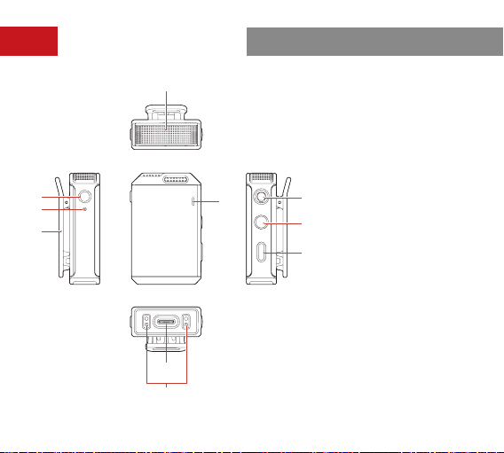
Inteace Description
A: Transmitter
①
④
⑤
⑦
⑧
⑥
⑦
⑧
⑨
⑩
⑥
②
③
① Built-in Microphone
② REC Button
③ REC Indicator
④ Back Clip
⑤ Status Indicator
⑥ 3.5mm Audio Input
Inteace
⑦ Power Button
⑧ Pairing/Noise
Cancellation Button
⑨ USB-C Inteace
⑩ Contacts
6
②
③
④
⑦
⑧
⑨
⑥
①
⑤
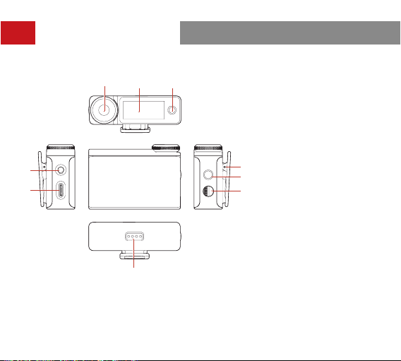
Inteace Description
B: Receiver
① On-Screen Home
Button
② AMOLED Touchscreen
③ Control Knob
④ 3.5mm TRS
Headphone Inteace
⑤ USB-C Inteace
⑥ Back Clip
⑦ Power/Screen Lock
Button
⑧ 3.5mm TRS Audio
Output Inteace
⑨ Contacts
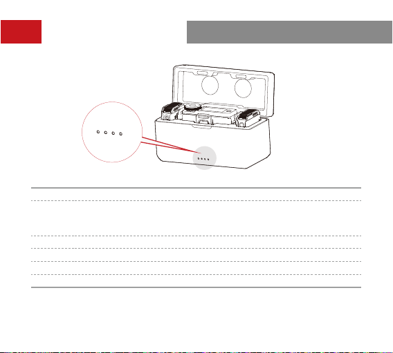
7
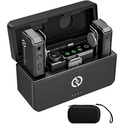
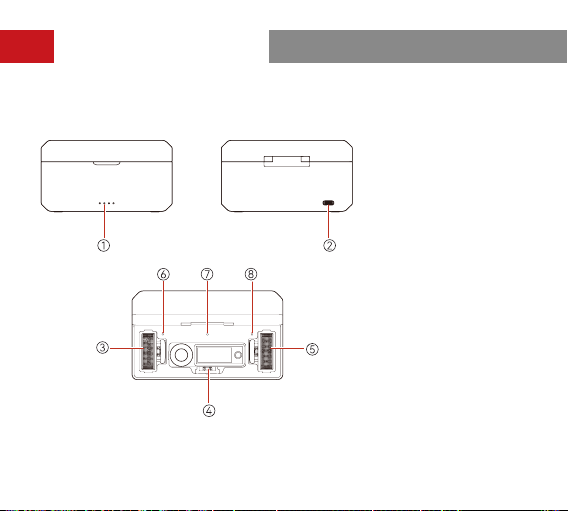
① Charging Case Batte
Level Indicator
② USB-C Inteace
③ Transmitter 1 Charging
/Storage Slot
④ Receiver Charging/
Storage Slot
⑤ Transmitter 2 Charging
/Storage Slot
⑥ Transmitter 1 Charging
Indicator
⑦ Receiver Charging
Indicator
⑧ Transmitter 2 Charging
Indicator
Inteace Description
C: Charging Case
8
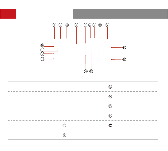
Display Description
① Recording Mode ⑦ USB Connection
Transmitter 1 Input
Volume
②
Noise Cancellation
Status
⑧
Headphone Connec-
tion
Transmitter 2 Recording
③ Screen Lock Status ⑨
Receiver Batte
Level
Transmitter 2 Signal
Strength
④
Transmitter 1 Batte
Level
⑩
Transmitter 1
Identier
Transmitter 2 Batte
Level
⑤ Transmitter 2 Identier
Transmitter 1 Signal
Strength
Transmitter 2 Input
Volume
⑥
3.5mm Audio Output
Connection
Transmitter 1
Recording
A: Receiver Main Inteace (Outside the Charging Case)
9
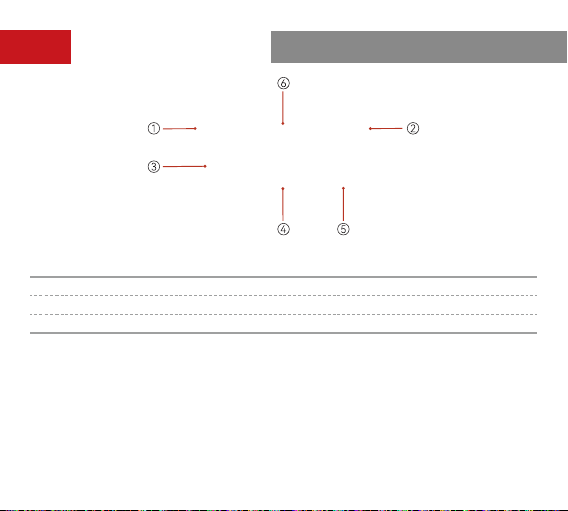
B: Receiver Main Inteace (in the Charging Case)
Display Description
① The Receiver Is in the Charging Case ④ Receiver Batte Level
② Charging Case Batte Level ⑤ Transmitter 2 Batte Level
③ Transmitter 1 Batte Level ⑥ Date & Time
10
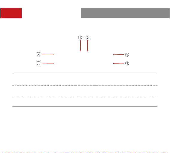
C: Receiver Output Volume Inteace
Settings:
To enter the receiver output volume inteace from the main inteace,
simply rotate the control knob. You can adjust the output volume on the left or
right channel by rotating the control knob or tapping on the touchscreen.
①
Output Volume on the Left
Channel
④
Output Volume on the Right
Channel
② Left Channel in Stereo Mode ⑤
Output Volume Bar on the Right
Channel
③
Output Volume Bar on the Left
Channel
⑥ Right Channel in Stereo Mode
Display Description
11
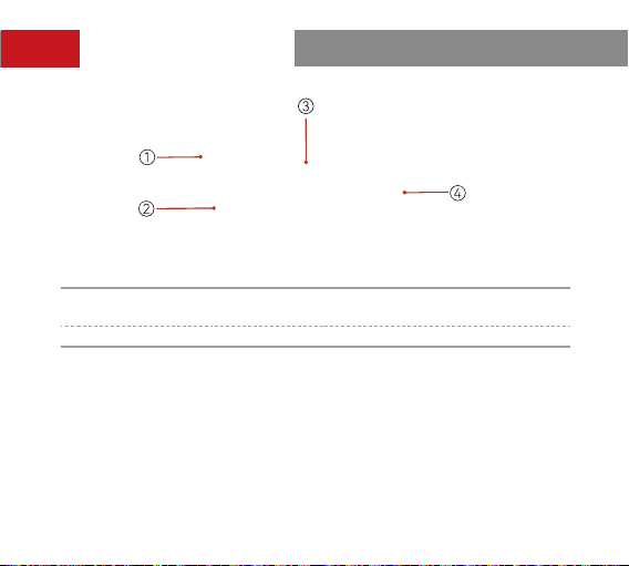
D: Receiver Quick Settings Inteace
Settings:
To enter the quick settings interface for transmitter 1 from the main
interface, simply tap the on-screen home button. You can switch between the
functions on the quick settings inteace by rotating the control knob or tapping
the function icons. To enter the quick settings inteace for transmitter 2, simply
rotate the control knob to the right. To return to the main inteace, simply tap the
on-screen home button again.
①
Quick Settings Inteace for
Transmitter 1
③ Mute Switch
② ENC Switch ④ Recording Switch
Display Description

12
Settings:
Press the control knob to enter the menu inteace from the main
inteace. Rotate the control knob or tap on the touchscreen to select a menu, and
then press the control knob or tap the menu to enter its sub-menu inteace. To
return to the previous inteace, simply tap the on-screen home button.
E: Receiver Menu Inteace
Display Description

13
Indicator Description
Transmitter Status Indicator
Pattern Description
Blue light ashing quickly Pairing
Blue light ashing slowly Disconnected from the receiver
Steady blue light Connected to the receiver
Steady green light ENC ON & Connected to the receiver
Green light ashing slowly
ENC ON & Disconnected from the
receiver
Steady pink light Upgrading
Red and blue lights ashing quickly
and alternately
Malfunctioning
Steady red light Mute ON
Breathing red light ashing Low batte
Breathing orange light, returning to
the previous state after 5 seconds
Power ON & Charging
Breathing orange light Power OFF & Charging
Steady orange light Power OFF & Fully charged

14
Charging Case Indicator
Pattern Description
One light outside the charging case
ashing when the charging case is
connected via USB
Charging case in charging mode
Four steady lights outside the charging
case
Charging case fully charged
Breathing light inside the charging case
Transmitter/Receiver in charging
mode
Steady light inside the charging case Transmitter/Receiver fully charged
Indicator Description
Transmitter REC Indicator
Pattern Description
Steady red light Recording
Light OFF Not recording
15
Pattern Batte Level
One LED ON, ashing red
Low batte. The transmitter and the
receiver cannot be charged using the
charging case.
One LED ON 25%
Two LEDs ON 50%
Three LEDs ON 75%
Four LEDs ON 100%
Indicator Description
16
Receiver Menu Description
Press the control knob to enter the menu inteace from the main inteace. The
menu operations are as follows:
1. Select
REC Mode
to set the receiver output mode.
a.
Stereo
b.
Mono
c.
Safety Track
2. Select
Mic Settings
to set the transmitter parameters.
a.
Mic Gain:
Press the control knob or tap to adjust the transmitter input gain.
b.
Auto Record:
The default value is
OFF
. If
Auto Record
is set to
ON
, the
transmitter will automatically sta internal recording when it is turned on.

17
Receiver Menu Description
c.
Auto OFF:
The default value is
15min
, indicating that the transmitter will
automatically turn o when it is not paired with the receiver and there
is no operation of it within 15 minutes. If
Auto OFF
is set to
Never
, the
transmitter will not turn o automatically.
d.
LED Brightness:
The default value is
Normal
. It allows you to set the
brightness of the transmitter status indicator light. You can set it to
Low
as
required.
e.
Storage:
Press the control knob or tap to view the remaining recording time
of the transmitter and format the transmitter storage (when the storage is
full, the earliest recording le will be automatically deleted).
3. Select
Phone Speaker
to set whether audio can be played on the phone
speaker without unplugging the receiver from the mobile phone.
a.
OFF:
Audio play on the phone speaker is disabled.
b.
ON:
Audio can be played on the phone speaker without unplugging the
receiver from the mobile phone.
4. Select
EQ
to congure audio settings.
a. Hi-Fi:
Select this mode to ensure Hi-Fi audio pickup with high restoration.
b. Low Cut:
Select this mode to lter low-frequency sound.
c. Vocal Boost:
Select this mode to increase voice intelligibility.

18
5. Select
System Settings
to congure system settings.
a.
Pairing:
Press the control knob or tap to set the receiver to pairing mode.
b.
Brightness:
Press the control knob or tap to adjust the brightness of the
receiver touchscreen.
c.
Upgrade Mode:
Press the control knob or tap to activate the device
upgrade process.
d.
Date:
Press the control knob or tap to set the date for the receiver. The
settings will be synchronized to the connected transmitter.
e.
Time:
Press the control knob or tap to set the time for the receiver. The
settings will be synchronized to the connected transmitter.
f.
Language:
Press the control knob or tap to set the device language to
English or Chinese.
g.
Facto Reset:
Press the control knob or tap to reset the device to the
default settings.
h.
Version Info:
Press the control knob or tap to check the receiver rmware
version, connected transmitter rmware version, and SN.
Receiver Menu Description
19
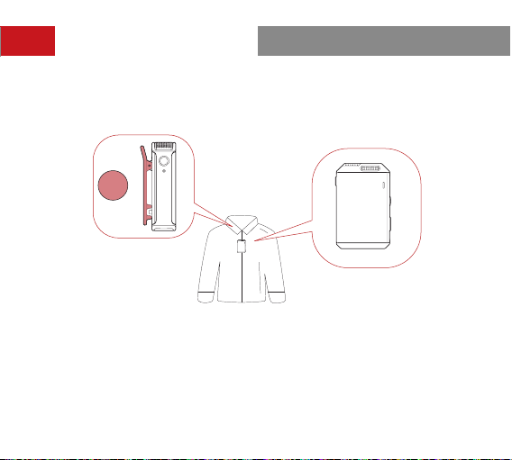
The preferred position for attaching the transmitter is the collar near the speaker's neck
area. If the speaker's voice is louder, position the transmitter in the upper chest area. The
transmitter can be attached via its back clip or the clip magnet.
Note:
Placement of the transmitter in dierent positions will result in recorded sound
volume uctuations. Avoid any obstructions of the transmitter during recording. It is
recommended to use the fur windshield to prevent audio inteerence when using the
transmitter outdoors.
Operation Instructions
20
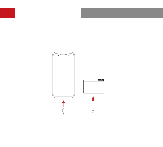
Operation Instructions
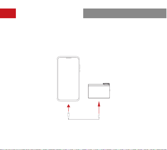
Connecting the Receiver to an iPhone
1. Connect the receiver to an iPhone using a USB-C to Lightning cable.
2. A USB connection icon will be displayed on the receiver touchscreen.
3. Open the recorder or camera app on the mobile phone to sta recording.
21
Operation Instructions
Note:
It is recommended to use the original USB-C to Lightning and USB-C to USB-C
cables. Otherwise, compatibility issues may occur, which could result in sound distoion
or other audio problems.
Connecting the Receiver to an Android Phone with a USB-C Inteace
1. Connect the receiver to an Android phone with a USB-C inteace using a USB-C to
USB-C cable.
2. A USB connection icon will be displayed on the receiver touchscreen.
3. Open the recorder or camera app on the mobile phone to sta recording.
22
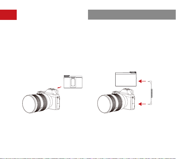
Connecting the Receiver to a Camera
1. Attach the receiver to a camera via the hot shoe or cold shoe using the back clip.
2. Connect the 3.5mm audio output inteace on the receiver to the 3.5mm audio input
inteace on the camera using a 3.5mm TRS to 3.5mm TRS cable.
3. Set the recording volume of the camera to the lowest and the output volume of the
receiver to the medium to ensure the best recording level.
Operation Instructions
23
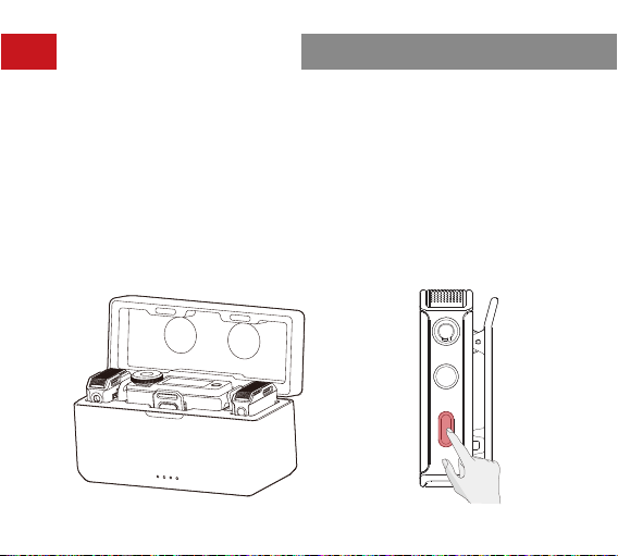
Pairing
The transmitter and the receiver are paired by default. Follow either of the follow-
ing two ways to pair the transmitter and the receiver if they are disconnected.
1. Auto pairing: Place the transmitter and the receiver in the charging case, and
they will pair automatically. (Figure 1)
2. Manual pairing: Turn on the transmitter and the receiver, and press and hold
the pairing button on the transmitter to enter pairing mode. In this case, the
transmitter status indicator light ashes quickly. Then, select
System Settings
on the receiver touchscreen and tap
Pairing
to sta pairing. If the transmitter
status indicator light turns steady blue, pairing is successful. (Figure 2)
Operation Instructions
Figure 1 Figure 2
24
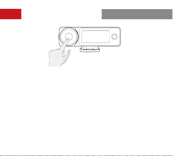
Operation Instructions
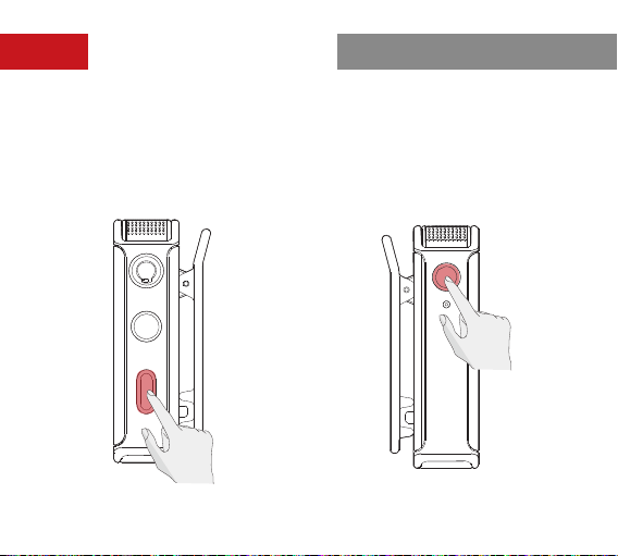
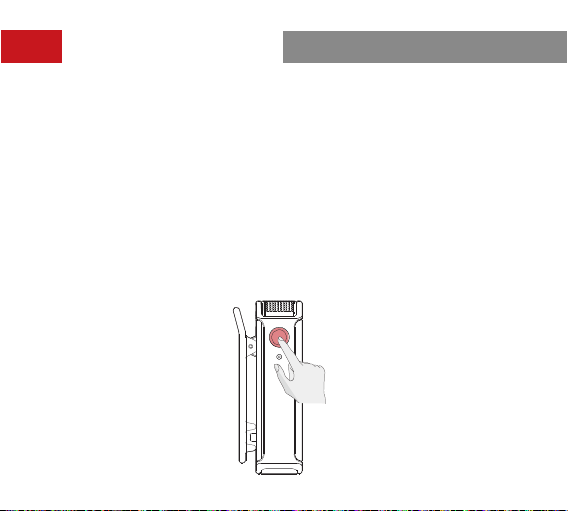
Press the noise cancellation button
on the transmitter to enable the noise
cancellation function. In this case, the
transmitter status indicator light turns
green.
Recording
Press the REC button on the
transmitter to enable the recording
function. In this case, the transmitter
REC indicator light turns steady red.
Noise Cancellation
25
Operation Instructions
Transmitter Recording
1. After turning on the transmitter, press the REC button to sta recording. In this
case, the transmitter REC indicator light turns steady red. Press the REC button
again to stop recording.
2. The recorded audio format of the transmitter is lossless 48 kHz/24-bit mono
WAV — an unprocessed RAW le. When the recording lasts for an extended
period, the le will be split up automatically eve 30 minutes.
3. The transmitter is suppoed with 8GB of built-in memo for storing the
recording les automatically. If the storage is full, newly recorded audio will
overwrite the older recorded audio automatically.
4. The recording le can be expoed by connecting the transmitter to a computer
or mobile phone.
5. The transmitter storage can be formatted via the receiver or other devices such
as a computer or mobile phone.

26
When new rmware is available, update the rmware by connecting the
transmitter, the receiver, and the charging case to a computer separately.
How to Update the Firmware:
Receiver Firmware Update
1. Select
System Settings
>
Upgrade Mode
from the main inteace on the
receiver touchscreen.
2. Connect the receiver to the computer using the USB-C cable provided and
copy the rmware update le to the receiver.
3. Unplug the USB-C cable from the computer after the le is copied. Then,
the receiver rmware update will sta automatically and the message
"Upgrading..." will be displayed on the receiver touchscreen. During the
rmware update, operations of the receiver are not allowed until the message
"Upgraded successfully. The device will resta soon." is displayed.
4. After the rmware is updated successfully, the receiver will resta automatically.
Firmware Update

27
Transmitter Firmware Update
1. Turn on the transmitter, connect the transmitter to the computer using the
USB-C cable provided, and copy the rmware update le to the transmitter.
2. Unplug the USB-C cable from the computer after the le is copied. Then,
the transmitter rmware update will sta automatically. During the rmware
update, the transmitter status indicator light turns steady pink and will return
to the previous state after the rmware update is completed.
3. After the rmware is updated successfully, the transmitter will resta
automatically.
Firmware Update

28
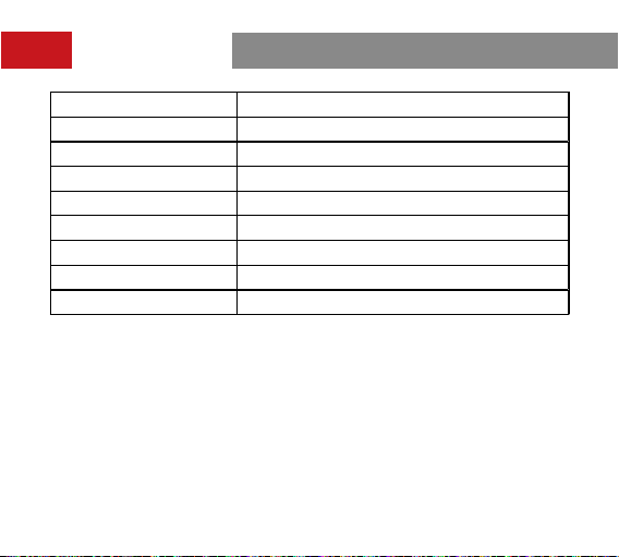
Specications
Name LARK MAX Transmitter
Dimensions
Approx. 48.5mm x 30.3mm x 19.37mm
(1.9" x 1.2" x 0.76")
Weight Approx. 33g (1.16oz)
Transmission Range Up to 820ft (250m) for LOS/197ft (60m) for NLOS
Modulation Mode GFSK
EIRP <20dBm
Operating Frequency 2400MHz–2483.5MHz
Batte Type RoHS-compliant LiPo
Batte Capacity 300mAh
Batte Voltage 3.87V
Batte Energy 1.161Wh
Charging Temperature 0° C to 45° C
Operating Temperature –20° C to 45° C
Charging Time <2 hours
Operating Time Approx. 7.5 hours
29
Specications
Recording Time Approx. 14 hours
Recorded Audio Format 48 kHz/24-bit WAV
Mic Polar Pattern Omnidirectional
Mic Sensitivity –36dBFS±1dB@1 kHz, 94dB SPL
Input Dynamic Range 98dB (Default)/106dB (Max)
Frequency Response 20 Hz–20 kHz (
Low Cut
disabled)
Signal-to-Noise Ratio 70dB
Sound Pressure Level 120dB SPL (Default)/128dB SPL (Max)
Equivalent Noise 24dBA
Note:
The transmission range is measured in an unobstructed outdoor
environment free of inteerence.

30
Specications
Name LARK MAX Receiver
Dimensions
Approx. 58mm x 40.83mm x 23.17mm
(2.3" x 1.6" x 0.9")
Weight Approx. 60g (2.1oz)
Touchscreen 1.1" AMOLED
Touchscreen Resolution 126 x 294 pixels
Modulation Mode GFSK
EIRP <20dBm
Operating Frequency 2400MHz–2483.5MHz
Batte Type RoHS-compliant LiPo
Batte Capacity 490mAh
Batte Voltage 3.87V
Batte Energy 1.896Wh
Charging Temperature 0° C to 45° C
Operating Temperature –20° C to 45° C
Charging Time <2 hours
Operating Time Approx. 9 hours

31
Specications
Name LARK MAX Charging Case
Dimensions
Approx. 115mm x 46mm x 63mm
(4.5" x 1.8" x 2.5")
Weight Approx. 193.5g (6.8oz)
Batte Type RoHS-compliant LiPo
Batte Capacity 2800mAh
Batte Voltage 3.85V
Batte Energy 10.78Wh
Charging Time <2 hours
Operating Temperature –20° C to 45° C
Charging Temperature 0° C to 45° C
Max Charging Times Approx. two times of charging for 2 TX and 1 RX
Note: The data provided above is based on laborato testing results.

32
Disclaimer
1. Please read and follow all the instructions carefully.
2. Please note all the warnings.
3. Do not place the product near or inside heating devices (including but not
limited to microwave ovens, induction cookers, electric ovens, electric heaters,
pressure cookers, water heaters, and gas stoves) to prevent the batte from
overheating and exploding.
4. Use only pas and accessories specied or provided by Hollyland. The use of
non-original pas or accessories may cause electric shock, re, explosion, or
other dangers.
5. Please hand over all maintenance work to qualied personnel. No matter what
kind of damage the product suers, such as damage to the power cable or
plug, liquid penetration, objects falling into the product, rain, dampness, failure
to work normally, or fall, maintenance is required.
33
If you encounter any problems in using the product or need any help, please
contact Hollyland Suppo Team via the following ways:
Statement
All copyrights belong to Shenzhen Hollyland Technology Co., Ltd. Without the
written approval of Shenzhen Hollyland Technology Co., Ltd., no organization or
individual may copy or reproduce pa or all of any written or illustrative content
and disseminate it in any form.
Trademark Statement
All the trademarks are owned by Shenzhen Hollyland Technology Co., Ltd.
Note:
Due to product version upgrades or other reasons, this User Manual will be
updated from time to time. Unless otherwise agreed, this document is provided as
a guide for use only. All representations, information, and recommendations in this
document do not constitute warranties of any kind, express, or implied.
Suppo
www.hollyland.com

34
FCC Requirement
Any changes or modications not expressly approved by the pay responsible for
compliance could void the user's authority to operate the equipment. This device
complies with Pa 15 of the FCC Rules. Operation is subject to the following two
conditions: (1) this device may not cause harmful inteerence, and (2) this device
must accept any inteerence received, including inteerence that may cause
undesired operation.
FCC Radiation Exposure Statement:
The device has been tested and found to comply with FCC SAR limits.
Note:
This equipment has been tested and found to comply with the limits for a Class
B digital device, pursuant to Pa 15 of the FCC Rules. These limits are designed
to provide reasonable protection against harmful inteerence in a residential
installation. This equipment generates, uses, and can radiate radio frequency
energy and, if not installed and used in accordance with the instructions,
may cause harmful inteerence to radio communications. However, there is
no guarantee that inteerence will not occur in a paicular installation. If this
equipment does cause harmful inteerence to radio or television reception, which
can be determined by turning the equipment o and on, the user is encouraged
to t to correct the inteerence by one or more of the following measures:

35
FCC Requirement
— Reorient or relocate the receiving antenna.
— Increase the separation between the equipment and receiver.
— Connect the equipment into an outlet on a circuit dierent from that to which
the receiver is connected.
— Consult the dealer or an experienced radio/TV technician for help.