803341 - Tap Installation Instructions - 02.17 - v2.02 Page 1 of 20
116
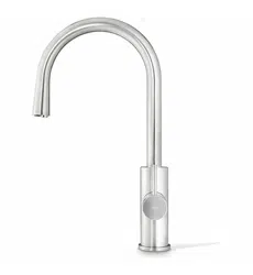
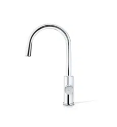
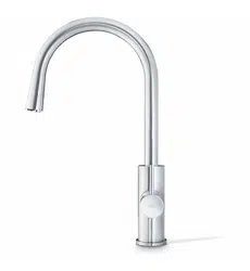
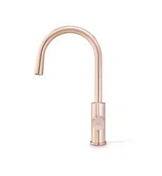
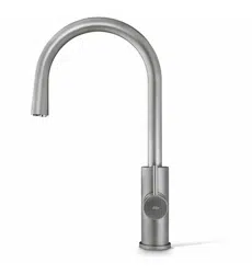
BC HydroTap Classic
Single
Bowl
For
Elite,Classic
and Arc/Cube
35mm hole
For
A-I-O 50mm and
Mixer taps 35mm
hole
Double Bowl
HydroTap Taps Installation
Hole positioning:
Position the tap such that it dispenses into the sink bowl with ample clearance for a cup or tea pot.
Alternatively, the tap could be mounted away from the sink using a font, available as an accessory.
TAP Recommended dispensing distance **
Elite 116 mm
HydroTap Classic 116 mm
HydroTap Arc/Cube 171 - 174 mm (Extended)
Classic All-In-One 211 mm
Celsius All-In-One 242 - 250 mm
Celsius Arc/Cube 220 mm
Mixer - Arc neck 220 mm
Mixer - Classic 270 mm
Mixer - Cube neck 220 mm
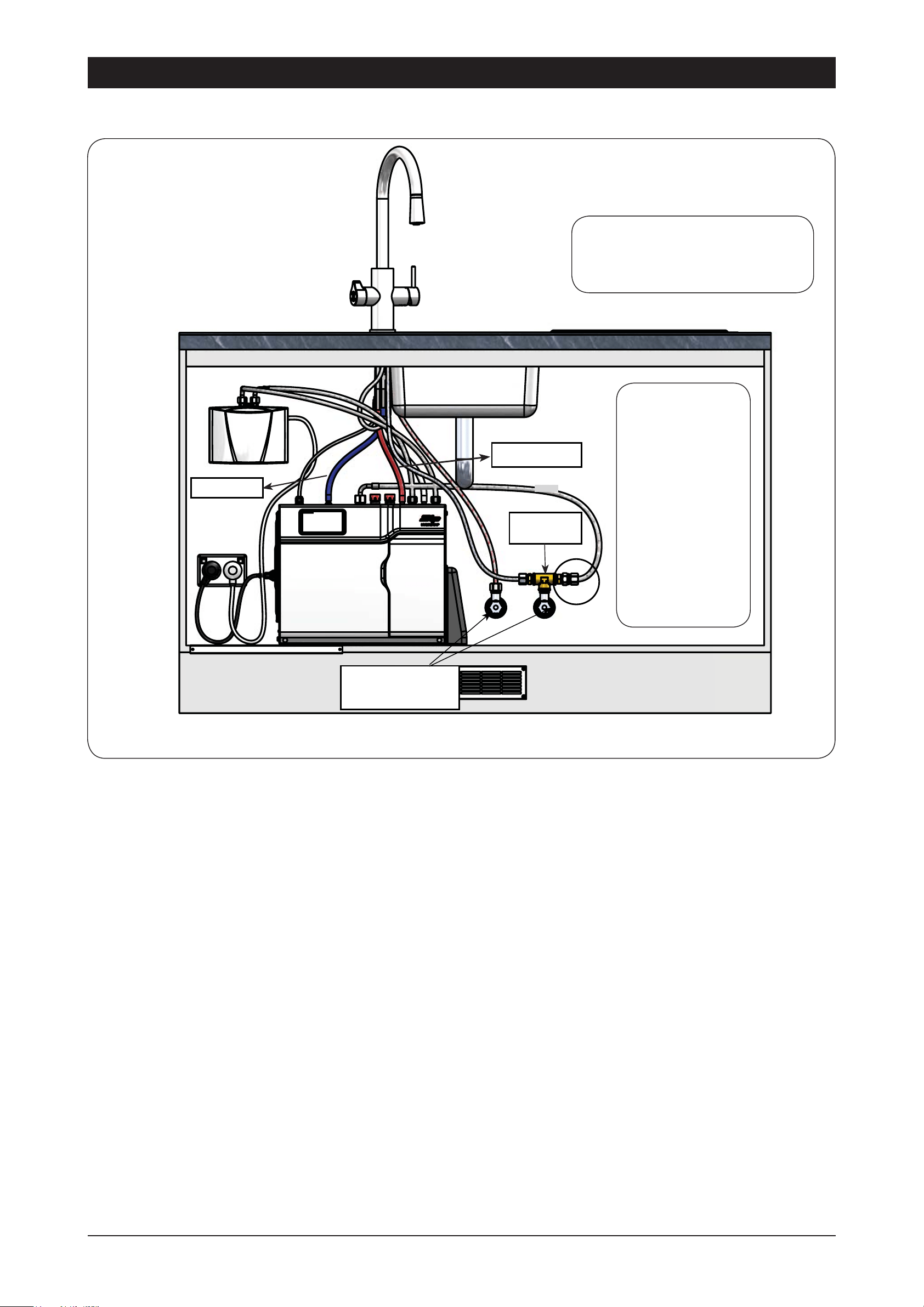
For new installations, It is recommended to fit the tap prior to installing the undersink unit.
Note: This book must be read in conjunction with the undersink installation manual and the user manual
Page 2 of 20 803341 - Tap Installation Instructions - 02.17 - v2.02
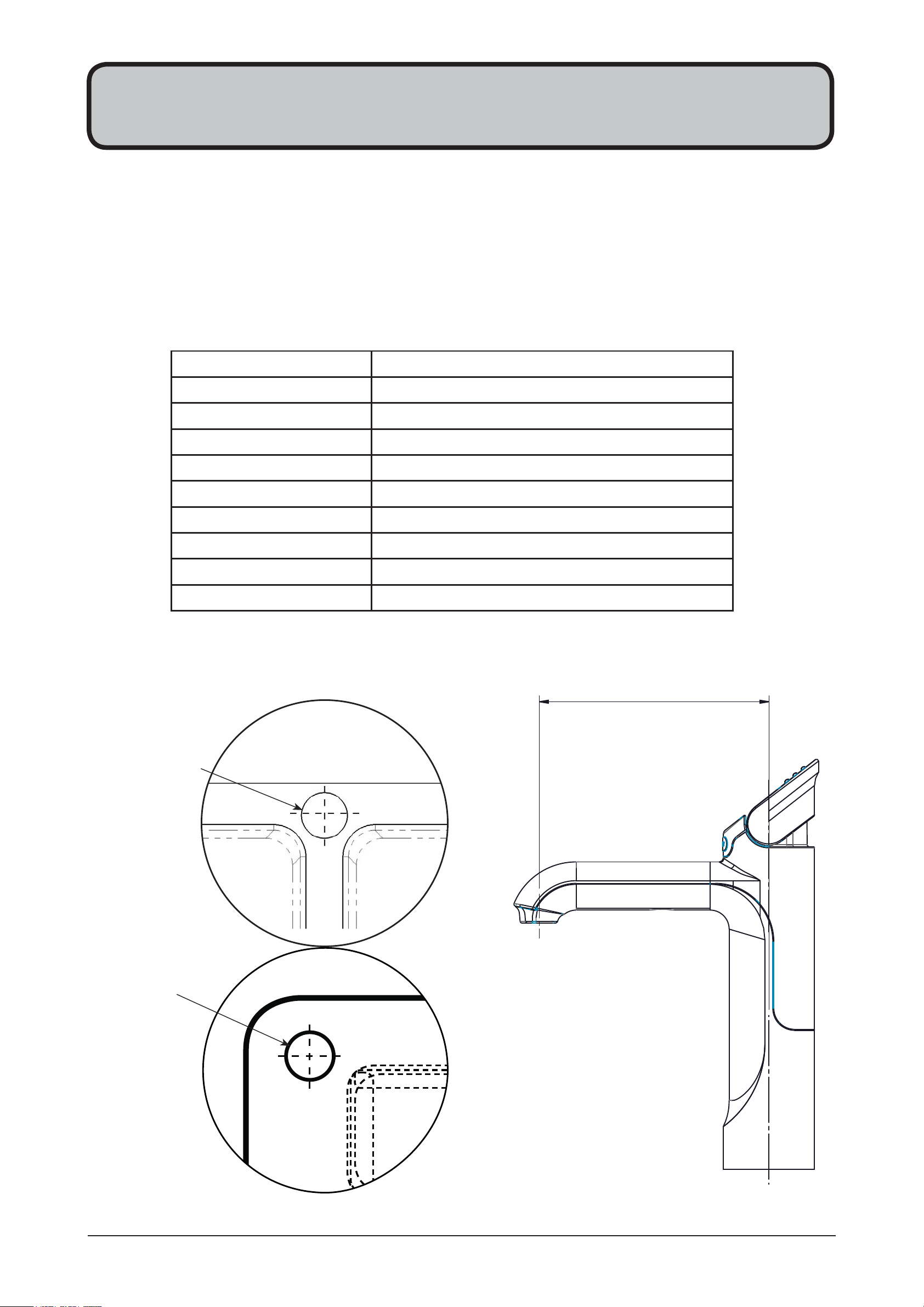
Apply a light smearing of silicon sealant on the
underside of the spacer to ensure a watertight fit.
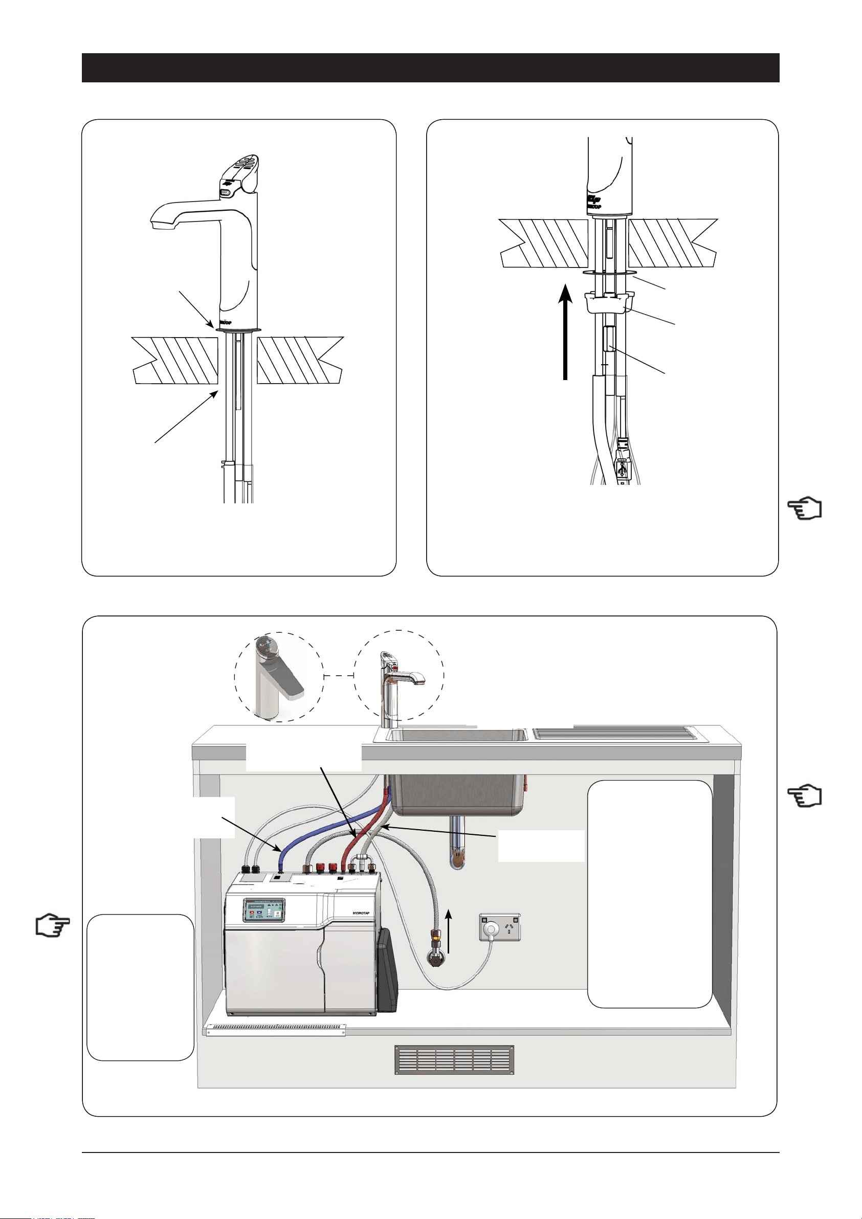
1.2
Cut a 35mm hole in the bench / sink top.
BENCH TOP
1.1
Ø35mm
ALL THREAD
ROD
STAINLESS
STEEL
SPACER
SPIDER
CLAMP
NUT
BLACK PLASTIC
SPACER
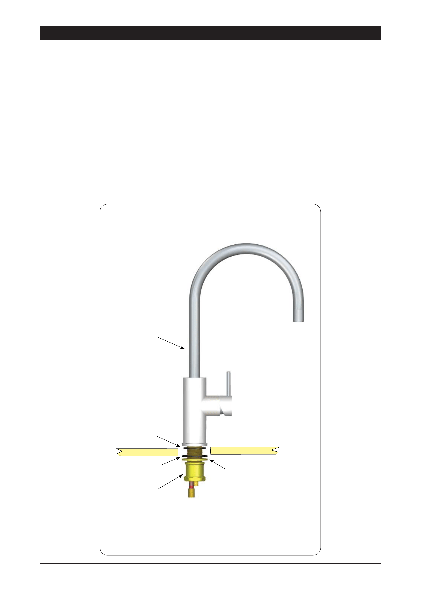
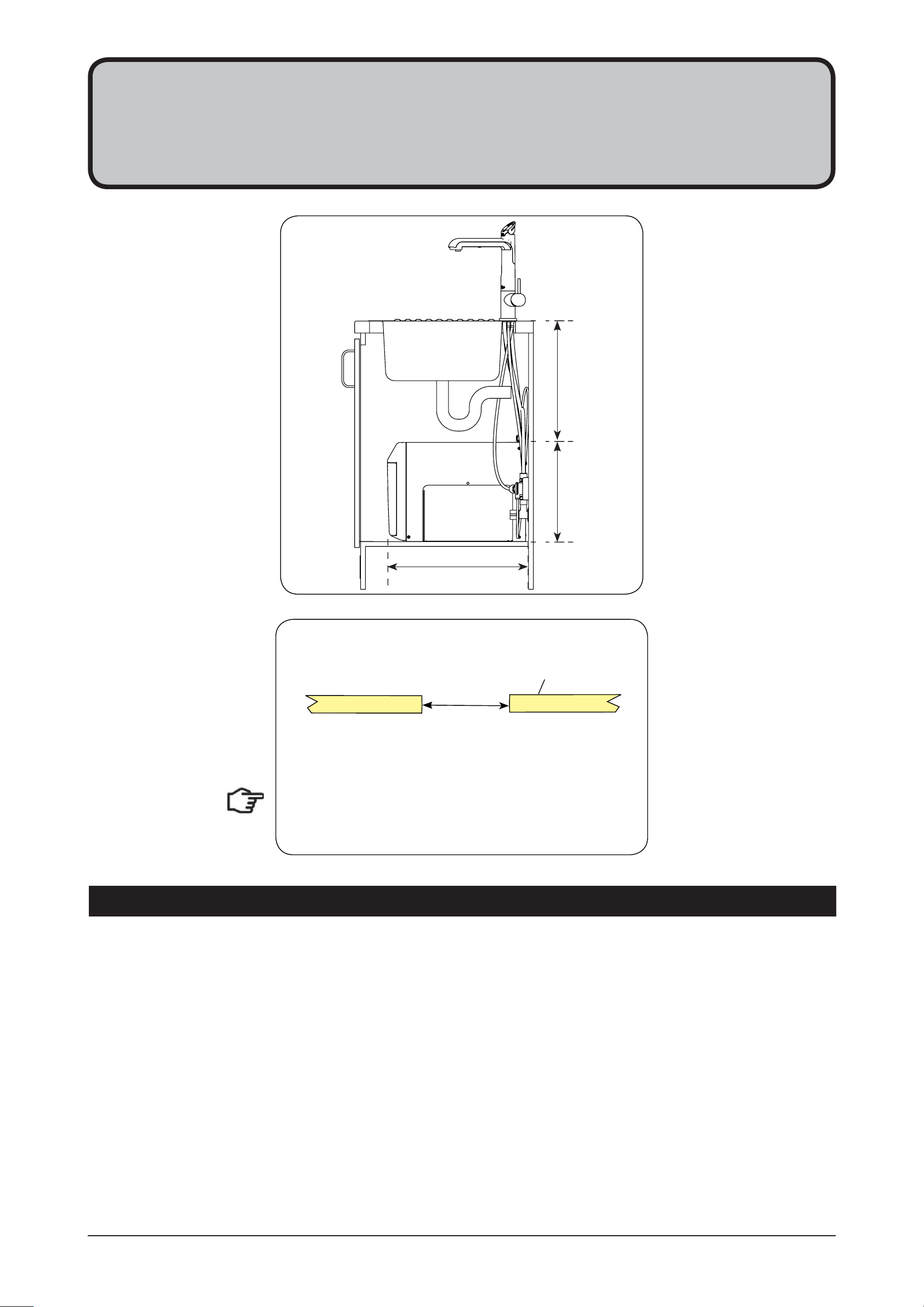
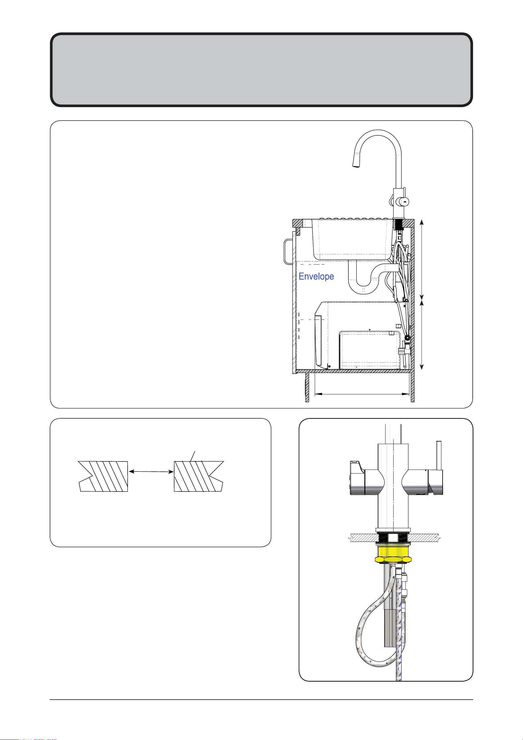
Tap assembly exploded view and kitchen layout side view.
470mm
335mm
Min 300mm
HydroTap Classic
EliteTap
1 - HydroTap Classic & Elite
803341 - Tap Installation Instructions - 02.17 - v2.02 Page 3 of 20
BLACK
PLASTIC
SPACER
1.3
Installation Instructions
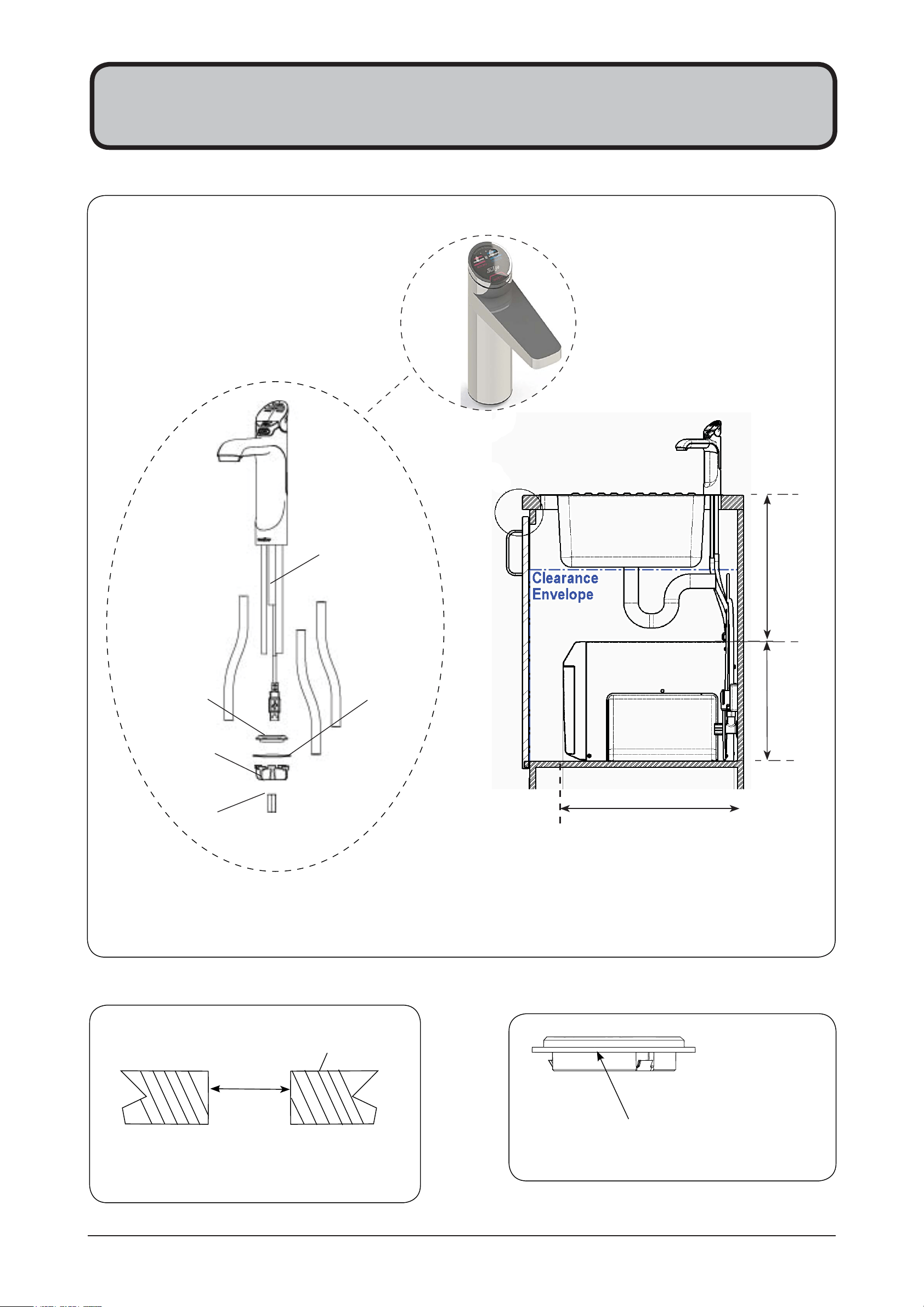
Pass all the hoses, tubes and USB lead
through the 35mm hole.
1.4
35mm hole
Note
Note: feed each of the three tubes and
electrical cable evenly in between the legs of
the SPIDER CLAMP when installing.
Fit the
STAINLESS STEEL
WASHER,
SPIDER CLAMP,
AND 6mm NUT.
6mm NUT
SPIDER CLAMP
STAINLESS
STEEL WASHER
Incoming water
Blue hose
to chilled
water outlet
Red hose to boiling
water outlet
Clear hose to
Vent
1.5
Note:
- Mains hose
length is 750mm
- Plug and Cord
length is 1800mm
Position the under
sink unit close
to the outlet tap,
within reach of
the hose and cord
lengths supplied
Note:
Note:
All
All
silicon tubes
silicon tubes
must be cut to
must be cut to
size. They must
size. They must
have a constant
have a constant
fall back to the
fall back to the
unit.
unit.
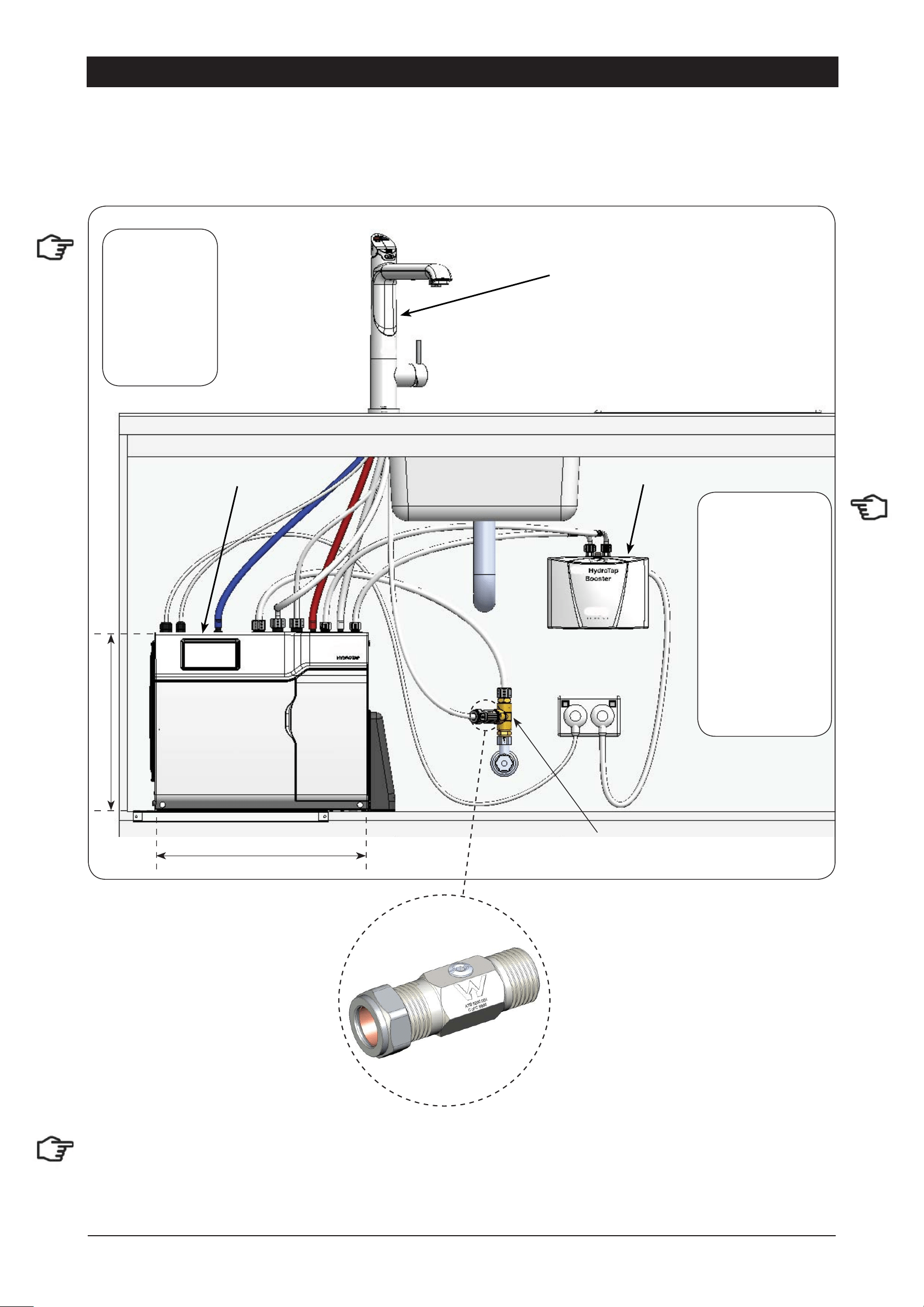
Typical HydroTap Installation (see section 5)
Page 4 of 20 803341 - Tap Installation Instructions - 02.17 - v2.02
2 - HydroTap Arc/Cube
The HydroTap Arc/Cube has a spout that may be fixed in one of 6 angular positions (depending on the
position of the rotary control) and fixed in one of two height positions. The spout is fixed and does not swivel.
NOTE: The tube kit must be fitted after the HydroTap has been mounted on the benchtop or sink.
Refer to the tube kit assembly instructions, supplied with the tap kit.
To reduce the risk of scalding, Position A should not
be selected with any of the Boiling water units.
(See fig. 1.8)
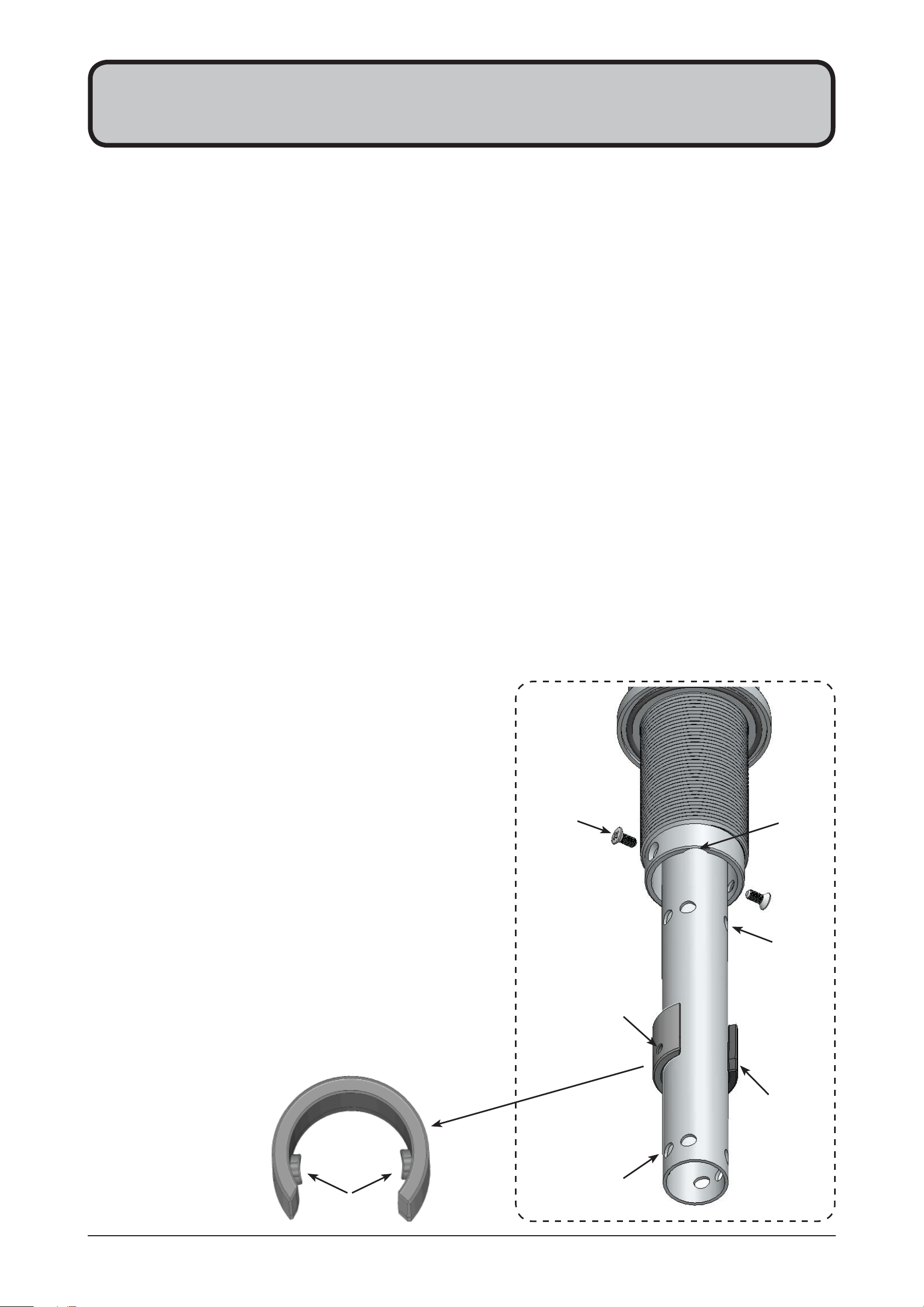
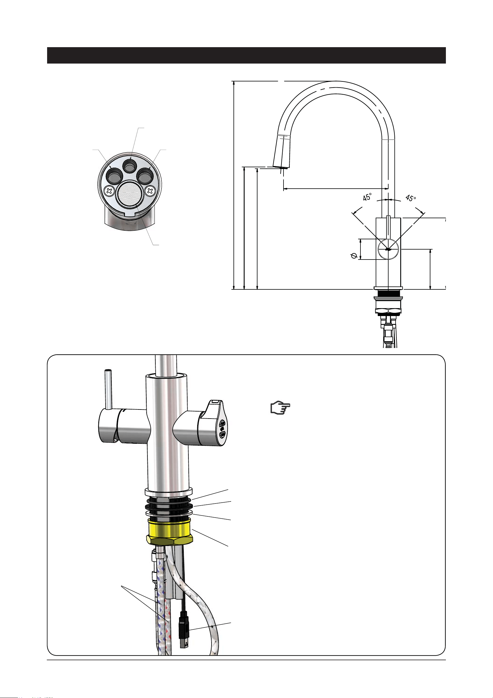
2.1
1.
Remove the 2 x spout locating screws and lower the spout to expose the plastic spring clip
NOTE: The plastic spring clip has two internal dimples that may be positioned in the 6 upper or 6 lower,
pre drilled holes in the spout (see diags. below & Figs. 1.7 & 1.8)
2.
To reposition the spout, gently spread the plastic spring clip to release the dimples from the spout
holes. When released, slide the clip on the spout so that it ends up between the two rows of holes.
3.
Rotate the plastic clip on the spout to orient the dimples, so they are in line with the newly selected
holes.
NOTE: When determining which of the 6 holes are required for the new spout height and orientation,
check the new plastic clip position will clear the undercut and that the wiring loom will not be pinched,
when assembled.
4.
Slide the plastic clip up/down to engage with the selected holes, making sure the two dimples engage
simultaneously with the two selected holes.
NOTE: The clip will not fit correctly if one dimple engages before the other. Both dimples must engage at
the same time.
5.
With the clip fitted to the newly selected holes,
carefully raise the spout (ensure the wiring loom is
a neat fit in the undercut and is located between the
open ends of the clip) until the clip locating holes are
in line with the spout locating screws.
6.
Replace the 2 x locating screws.
7.
If mounting on an uneven surface, apply a light
smearing of silicon sealant on the O ring to ensure a
watertight fit. (See fig. 1.9)
8.
Pass the assembly through the 35mm hole and
position the tap so it discharges into the sink.
9.
Fit the lower rubber seal to the threaded extension.
10.
Secure the tap in position with the metal washer and
nut.
11.
Fit the tube kit, as supplied.
To change the spout position
Spout locating
screws (2)
Plastic spring
clip
Upper locating
positions
Lower locating
positions
Clip locating
holes (2)
Undercut
for loom
Plastic spring clip
Dimples
803341 - Tap Installation Instructions - 02.17 - v2.02 Page 5 of 20
Installation Instructions
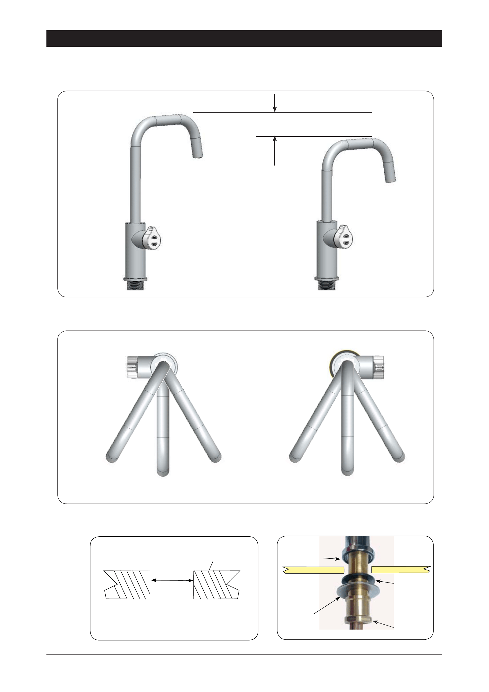
AA
Left Hand Control Right Hand Control
B
C
C
B
50mm
Height adjustment (Fixed position options)
Angular adjustment (Fixed position options)
2.2
O-RING
LOWER
RUBBER
WASHER
WASHER
NUT
2.3
2.4
Mounting (See table on Page 11 )
Cut a 35mm hole in the bench / sink top.
BENCH TOP
Ø35mm
NOTE: Position A is
not recommended with
Boiling water units
Page 6 of 20 803341 - Tap Installation Instructions - 02.17 - v2.02
Cut a 35mm hole in the bench / sink top.
SINK TOP
3.1
35mm
Note: make sure the tap location will allow
the nozzle to drain into the sink.
Tap assembly exploded view and kitchen layout side view.
BRAIDED
HOSE x 3
3 - Mixer Tap Installation
3.2
O-RING
LOWER
RUBBER
WASHER
WASHER
NUT
External
Mains
Blue band
Mixer IN
Red band
Mixer Out
Note
Note
:
The mixer tap requires a Restrictafl ow valve,
as supplied, to be fi tted in the cold water sup-
ply line, from the isolation valve tee piece, to
the mixer tap. (See Fig. 1.13)
Min 300mm
803341 - Tap Installation Instructions - 02.17 - v2.02 Page 7 of 20
3.3
Installing the Mixer Tap
(Classic, Arc and Cube)
Installation Instructions
Sink top
O-ring
Lower seal
Washer
Securing nut
Mixer tap
Arc Mixer Tap
•
Fit the O-ring into the recess on the underside of the Mixer tap. (Note: If mounting on an uneven
surface, a light smear of silicone on the O-ring will ensure a water tight seal)
•
Pass the tap tubes and threaded extension through the 35mm hole and position the tap so that it
discharges into the sink.
•
Fit the lower rubber seal to the threaded extension.
•
Secure the tap in position with the metal washer and Nut.
•
Affix the three hoses to the tap. Match the hose colours to the coloured bands on the copper extension
tubes. (See diag. 1.11)
Page 8 of 20 803341 - Tap Installation Instructions - 02.17 - v2.02
Installation Instructions
3.4
COLD isolation valve
(Not supplied)
HydroTap
Mixer
Connections
RED
CLEAR
BLUE
WHITE
Restrictafl ow valve
(Supplied)
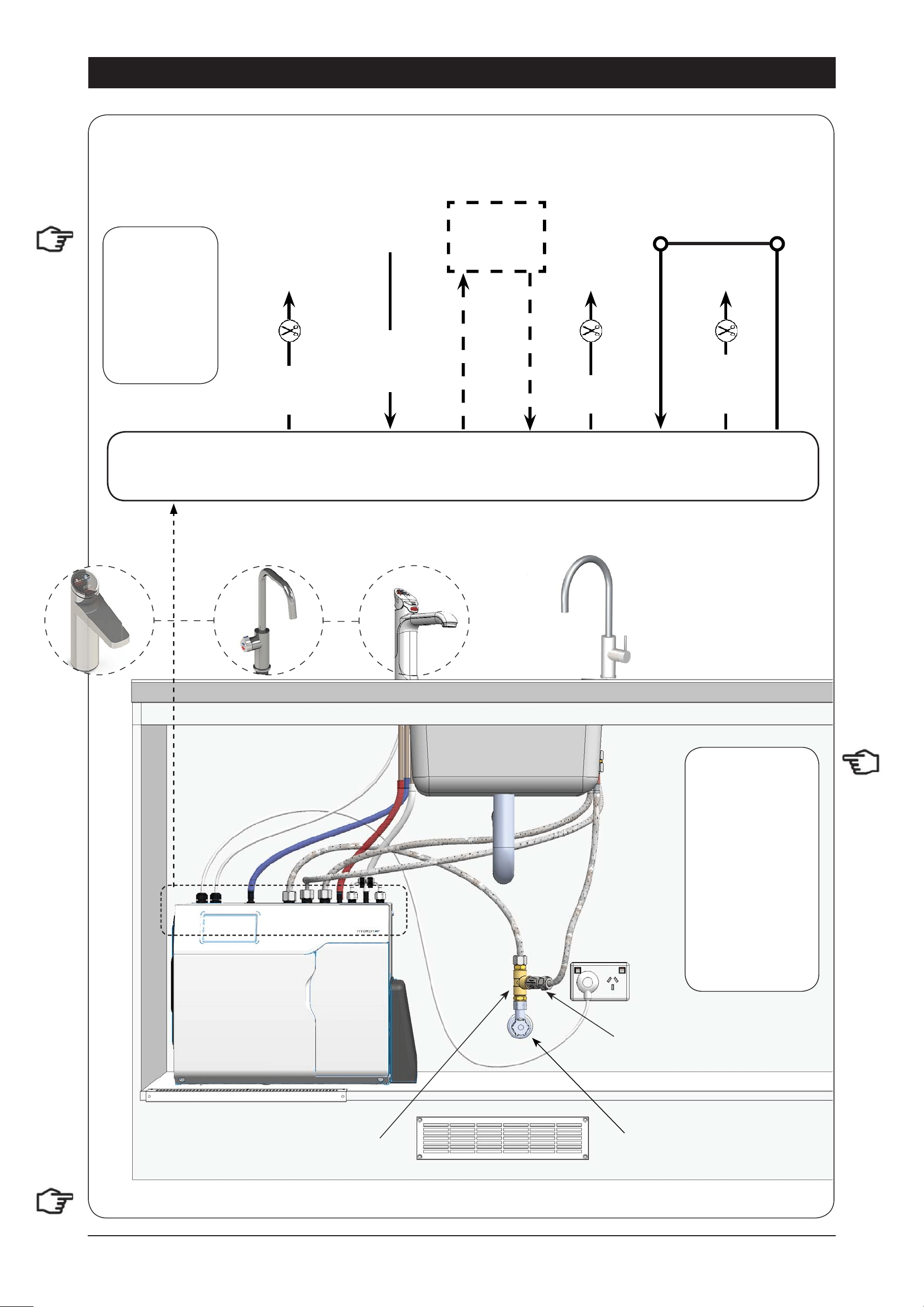
Typical HydroTap 4-in-1 Installation (see section 5)
Tee piece
(Supplied)
POWER
CORD
USB
CHILLED
OUTLET
MAINS
IN
MIXER
OUT
MIXER
IN
BOILING
OUT
BYPASS
IN
VENT
BYPASS
OUT
Note:
- Mains hose
length is 750mm
- Plug and Cord
length is 1800mm
Position the under
sink unit close
to the outlet tap,
within reach of
the hose and cord
lengths supplied
Note:
Note:
All
All
silicon tubes
silicon tubes
must be cut to
must be cut to
size. They must
size. They must
have a constant
have a constant
fall back to the
fall back to the
unit.
unit.
Note:
The tube lengths are matched to the pumps performance and therefore CANNOT be lengthened
803341 - Tap Installation Instructions - 02.17 - v2.02 Page 9 of 20
Cut a 50mm hole in the bench / sink top.
SINK TOP
4.1
50mm
Note
Note: make sure the tap location will allow the
nozzle to drain into the sink. (See Page 11)
4 - Classic All-In-One Tap
Installation
Min 300mm335mm
470mm
4.2
• Fit the seal ring to the base
of the tap and If mounting on an uneven surface, apply
a light smear of silicone
sealant to ensure a watertight seal
• Mount the tap on top of the cut out hole after passing the usb cable and tubes through the 50mm hole
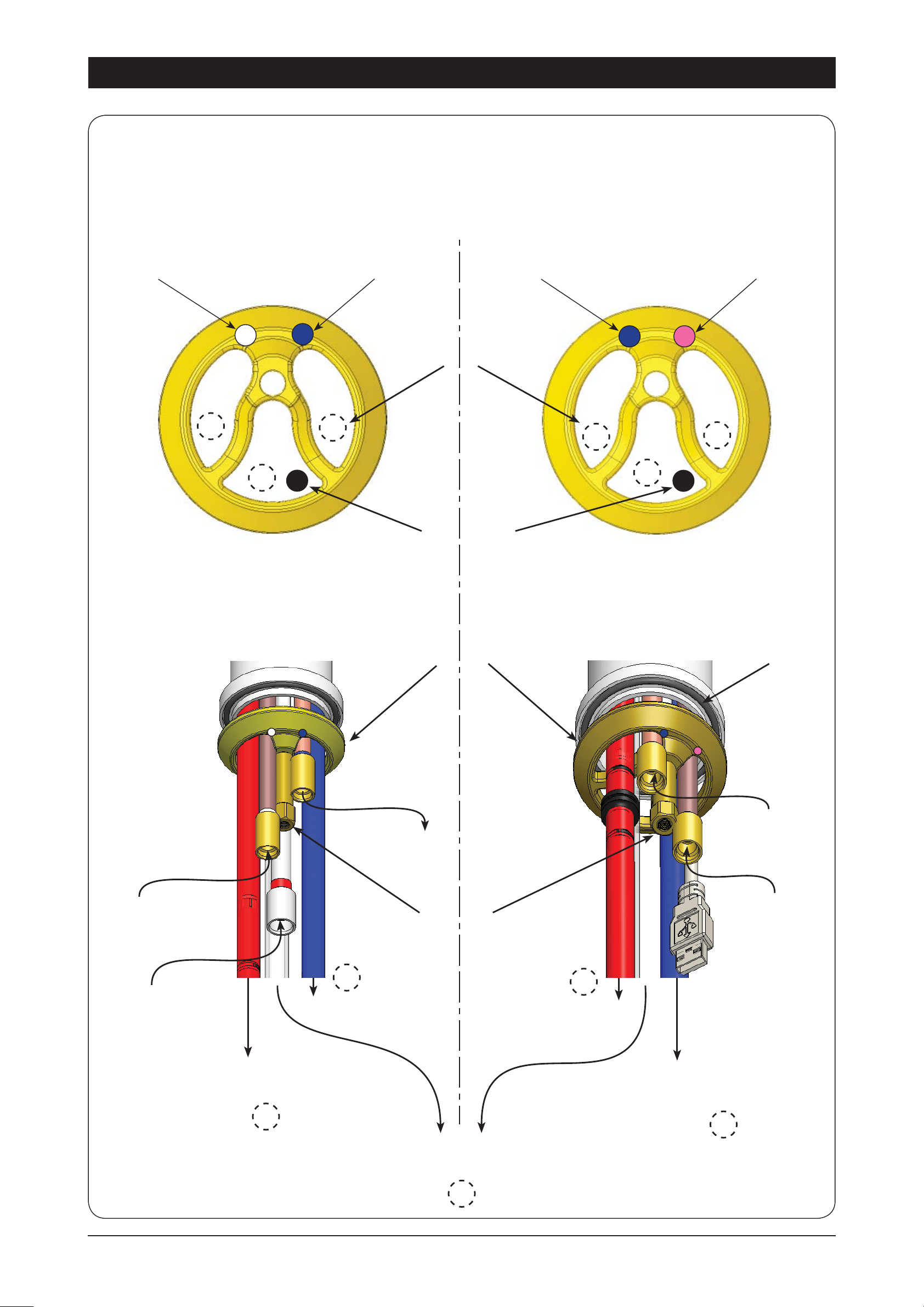
• Thread the cable and silicon tubes through the circular clamp block (Check the tube colour alignment with the
coloured dots on the clamp block). (See fig 1.16)
• Clamp the assembly in position using the threaded nut and clamp block
• Working from inside the cupboard, attach the braided hoses to the tube extensions (ensure the seals on the end of
the hoses are lubricated). Check the correct position for Hot and Cold connections by matching the colours on the
braided hoses with the coloured markings on the copper extension tubes. (See fig. 1.18)
• Test for leaks after all the connections have been secured.
Installation Procedure
Page 10 of 20 803341 - Tap Installation Instructions - 02.17 - v2.02
FIXING NUT
4.3
Installation Instructions
4.4
CLAMP BLOCK O-RING
AIO Vented assy
BLUE to Chiller
connection
CLEAR
to vent
RED to Boiling
connection
From Mixer
OUT
AIO Mains assy
BLUE mark
WHITE mark
BLUE mark RED mark
Clamp Block markings and silicon tube positions,
viewed from underneath
RED to Boiling
connection
BLUE to Chiller
connection
Mains IN
From HWS
connection
Mains IN
To Mixer
IN
R
SILICON TUBES
USB CABLE
R
C
B
C
B
R
R
C
B
B

803341 - Tap Installation Instructions - 02.17 - v2.02 Page 11 of 20
4.5
Installation Instructions
CLAMP
BLOCK
•
Screw the braided hoses
into the extension tubes.
Ensure the o-rings
are lubricated prior to
assembly and that the
braided hoses, with
coloured markings,
are correctly matched
with the colours on the
extension tubes and
on the clamp block (as
indicated).
•
Make sure all tubes and
hoses are firmly secured.
Braided
hoses
Vented braided hose positions
Mains braided hose positions
BLUE to
Mixer IN
HOT IN
from HWS
WHITE
Mains IN
RED from
Mixer OUT
Underside view
BLUE
Mains IN
RED
Extension
tubes
Typical Vented assembly
External HOT & COLD
isolation valves
(Not supplied)
Tee piece
(Supplied)
Typical All-in-1 Mains Installation (see section 5)
4.6
Note:
Note:
All silicon tubes must
All silicon tubes must
be cut to size. They must have a
be cut to size. They must have a
constant fall back to the unit.
constant fall back to the unit.
RED Hot
BLUE Chilled
Note:
- Mains hose
length is 750mm
- Plug and Cord
length is 1800mm
Position the under
sink unit close
to the outlet tap,
within reach of
the hose and cord
lengths supplied
Page 12 of 20 803341 - Tap Installation Instructions - 02.17 - v2.02
Installation Instructions
4.7
Typical All-In-One Vented assembly with Booster heater (See section 5)
Booster
BC Unit
A-I-O Tap
400mm
335mm
Restrictaflow valve & Tee piece
(Supplied)
Note:
The All-In-One vented taps require a Restrictafl ow valve and Tee piece, as supplied, to be fi tted in the
cold water supply line, from the isolation valve (Not supplied), to the mixer tap. (See diagrams)
Restrictaflow valve
Note:
- Mains hose
length is 750mm
- Plug and Cord
length is 1800mm
Position the under
sink unit close
to the outlet tap,
within reach of
the hose and cord
lengths supplied
Note:
Note:
All
All
silicon tubes
silicon tubes
must be cut to
must be cut to
size. They must
size. They must
have a constant
have a constant
fall back to the
fall back to the
unit.
unit.
803341 - Tap Installation Instructions - 02.17 - v2.02 Page 13 of 20
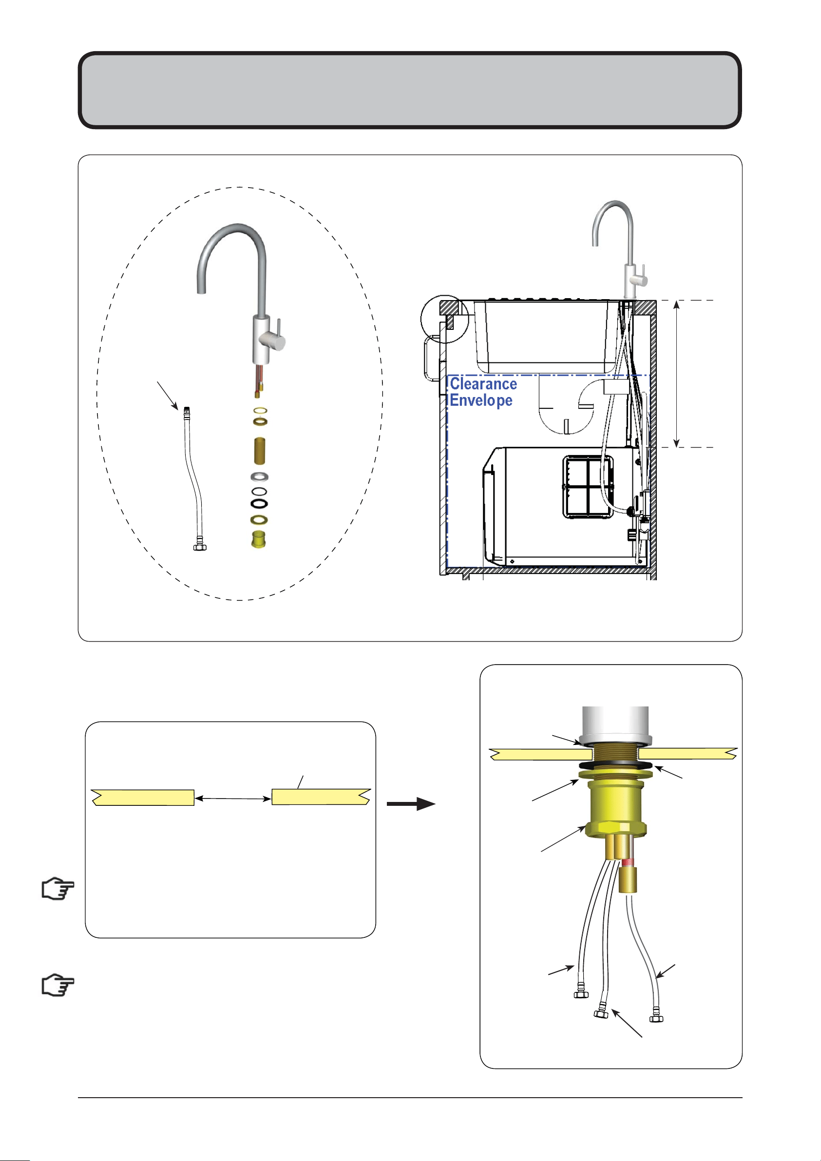
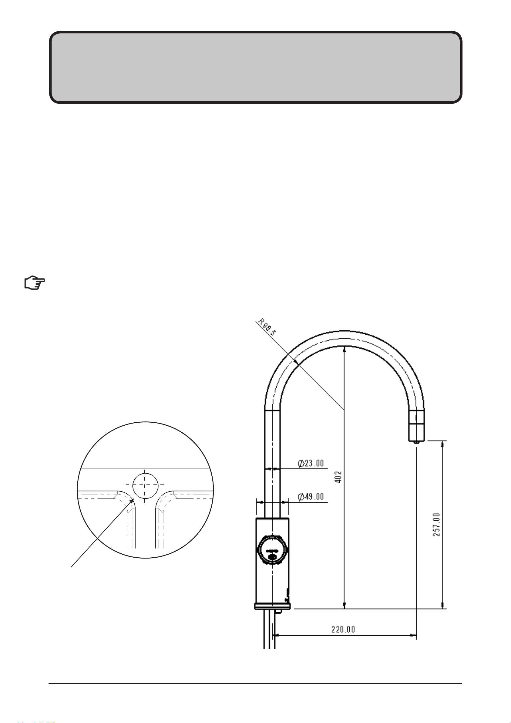
5.1
5 - Celsius All-In-One Tap
Installation
464
Clearance
Min 300mm335mm
Cut a 50mm hole in the bench / sink top. Note:
make sure the tap location will allow the nozzle
to drain into the sink
5.2
BENCH TOP
Ø 50mm
Special Tools Required:
In addition to normal tools, the following will be
required:
•
50mm diameter sheet metal hole punch for
sink tops. (Not supplied)
•
50mm diameter hole saw for timber bench
tops. (Not supplied)
•
54mm AF tube spanner or wrench (Not
supplied) for fixing tap assembly.
5.3
•
Pass all the hoses, tubes and USB lead through
the 50mm hole.
•
Ensure the black rubber seal is correctly
positioned to give a water tight seal
•
Secure the rubber & steel washers and large nut
from inside the cupboard space, as shown.
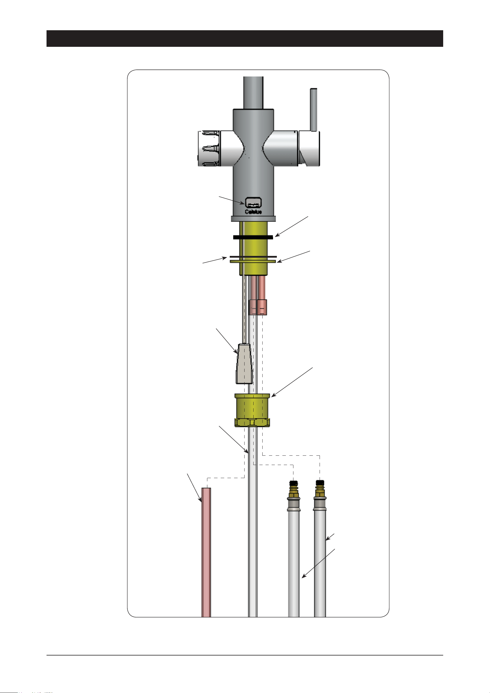
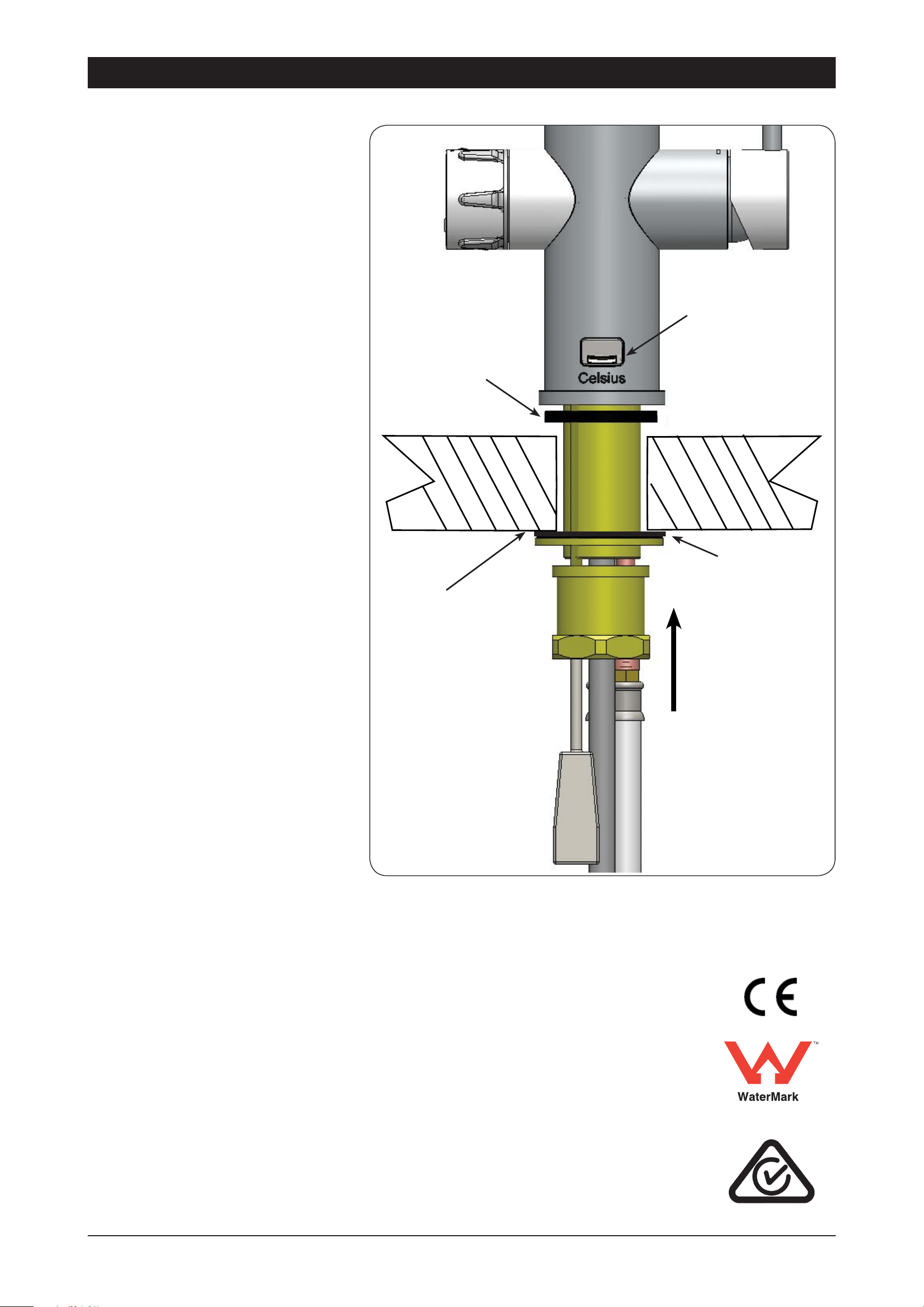
Page 14 of 20 803341 - Tap Installation Instructions - 02.17 - v2.02
Installation Instructions
+RW&ROG
:DWHU2XWOHW
&KLOOHG:DWHU
2XWOHW
%RLOLQJ:DWHU
2XWOHW
6WHDP9HQW
2XWOHW
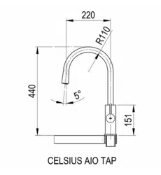
42.9
85
439.5
258
255
220mm
(Hot & Cold Outlet)
Swing
Swing
151
Underside of spout of Celisus AIO tap.
5.4
5.5
Note:
Note:
Trim all plastic tubes to min-
Trim all plastic tubes to min-
imise any dead leg of water.
imise any dead leg of water.
O-RING SEAL
BLACK RUBBER SEAL
STEEL WASHER
BRASS NUT
USB PLUG
HOT & COLD
BRAIDED HOSES
803341 - Tap Installation Instructions - 02.17 - v2.02 Page 15 of 20
Installation Instructions
BRASS NUT
USB PLUG
FROM BOILING OUTLET
AT BASE UNIT OR
COMMAND CENTRE
5.6 Plumbing Connection
COLD MAINS HOT MAINS
JG STRAIGHT
CONNECTOR
BRAIDED HOSE
FOR MIXED WATER
FROM CHILLED OUTLET
AT BASE UNIT OR
COMMAND CENTRE
FROM STEAM
VENT OUTLET
OF COMMAND
CENTRE
3 WAYS MULTI
CHANNEL
BOILING
OUTLET
CHILLED
OUTLET
STEAM
VENT
BOTTOM END OF
3-WAY SILICONE TUBE
3 STAINLESS
STEEL TUBES
TOP END OF 3-WAY
SILICONE TUBE
STEAM
VENT
BOILING
OUTLET
CHILLED
OUTLET
Page 16 of 20 803341 - Tap Installation Instructions - 02.17 - v2.02
External HOT & COLD
isolation valves
(Not supplied)
Tee piece
(Supplied)
Typical All-In-One Mains Installation
5.7
Note:
Note:
All silicon tubes must be
All silicon tubes must be
cut to size. They must have a con-
cut to size. They must have a con-
stant fall back to the unit.
stant fall back to the unit.
RED Boiling
BLUE Chilled
Note:
- Mains hose
length is 750mm
- Plug and Cord
length is 1800mm
Position the under
sink unit close
to the outlet tap,
within reach of
the hose and cord
lengths supplied
Installation Instructions
803341 - Tap Installation Instructions - 02.17 - v2.02 Page 17 of 20
Special Tools Required:
In addition to normal tools, the following will be required:
•
35mm diameter sheet metal hole punch for sink tops. (Not supplied)
•
35mm diameter hole saw for timber bench tops. (Not supplied)
•
42mm AF tube spanner or wrench (Not supplied) for fixing tap assembly.
6 - Celsius
Tap Installation
Hole positioning:
Position the tap such that it dispenses
into the sink bowl.
NOTE: Taps are available with ARC or CUBE neck options.
35mm hole
Double Bowl

Page 18 of 20 803341 - Tap Installation Instructions - 02.17 - v2.02
Cut a 35mm hole in the bench / sink top.
BENCH TOP
6.1
Ø35mm
HOT & COLD
BRAIDED
HOSES
CHILLED
TUBE
BRASS
WASHER
BLACK RUBBER
Seal
BRASS
NUT
USB
PLUG
SPARKLING
TUBE
JG
Y-PIECE
Note: Trim all plastic
tubes to minimise any
dead leg of water.
Chilled Sparkling Tap components
CSHA Tap connections
RUBBER
Washer
6.2
803341 - Tap Installation Instructions - 02.17 - v2.02 Page 19 of 20
HOT & COLD
BRAIDED
HOSES
BOILING
or
CHILLED
TUBE
BRASS
WASHER
BLACK RUBBER
SEAL
BRASS
NUT
VENT
TUBE
USB
PLUG
BHA and CHA Tap connections
RUBBER
Washer
Boiling
model Vent
outlet
6.3
Page 20 of 20 803341 - Tap Installation Instructions - 02.17 - v2.02
•
Pass all the hoses, tubes and
USB lead through the 35mm
hole.
•
Ensure the black rubber seal
is correctly positioned to give
a water tight seal
•
Secure the rubber & brass
washers and large nut from
inside the cupboard space, as
shown.
FIT THE
RUBBER WASHER,
BRASS WASHER,
AND LARGE NUT
BLACK
RUBBER
SEAL
35mm HOLE
IN BENCH
TOP
Tap Installation
RUBBER
WASHER
Boiling
model Vent
outlet
6.4
WMKA00099
AS 3498
NZ Office
Zenith Heaters Limited,
IRD No. 95 640 729
Unit 2/15 Moselle Avenue,
Henderson, Auckland 0610
New Zealand.
Website: www.zenithheaters.co.nz
Int. Phone: +(64 9) 838 8612
Telephone: 0800 558055
Facsimile: 0800 559055
Head Office
Zip Heaters (Aust) Pty. Ltd.
ABN: 46 000 578 727
67 Allingham Street
Condell Park NSW 2200
Postal: Locked Bag 80
Bankstown 1885 Australia
Website: www.zipwater.com
Facsimile: (02) 9796 3858
Telephone: (02) 9796 3100
Sales & Service.
Free Call: 1 800 63 86 33
Customer Care.
Free Call: 1 800 42 43 44