INSTALLATION AND OPERATION INSTRUCTIONS
30-BAY SLIM
40-BAY SLIM
50-BAY SLIM
60-BAY SLIM
72-BAY SLIM
SAFETY INFORMATION
WARNING
If the information in these instructions are
not followed exactly, a fire or explosion
may result causing property damage,
personal injury or loss of life.
Do not store or use gasoline or other flammable vapors
and liquids in the vicinity of this or any other appliance.
INSTALLER: LEAVE THIS MANUAL WITH THE APPLIANCE.
CONSUMER: RETAIN THIS MANUAL FOR FUTURE REFERENCE.
APRIL 2021 EDITION -VERSION 1

IMPORTANT INSTRUCTIONS ......................................................................................................................................... 3
UNPACKING AND TESTING APPLIANCE ................................................................................................................... 4
GROUNDING APPLIANCE ............................................................................................................................................... 4
LOCATING THE FIREPLACE ........................................................................................................................................... 4
30-
BAY SLIM
.......................................................................................................................................................................
5
40-
BAY SLIM
.......................................................................................................................................................................
6
50-
BAY SLIM
.......................................................................................................................................................................
7
60-
BAY SLIM
....................................................................................................................................................................... 8
72-
BAY SLIM
........................................................................................................................................................................9
SAFETY DRILL SCREW AREA ..................................................................................................................................... 10
HARD-WIRE INSTALLATION ....................................................................................................................................... 10
FOR BATHROOM USE ................................................................................................................................................... 11
OUTDOOR INSTALLATIONS ........................................................................................................................................ 12
INSTALLATION ................................................................................................................................................................ 13
MEDIA OPTIONS .............................................................................................................................................................. 19
OPERATION ....................................................................................................................................................................... 20
INSTALLING WALL THERMOSTAT ........................................................................................................................... 22
REPLACEMENT PARTS .................................................................................................................................................. 23
EXPLODED VIEW ............................................................................................................................................................ 25
TROUBLE SHOOTING ..................................................................................................................................................... 27
SERVICE HISTORY .......................................................................................................................................................... 28
WARRANTY ...................................................................................................................................................................... 29
2
WIRING DIAGRAM ............................................... .......................................................................................................... 26
TABLE OF CONTENTS
Please read and carefully follow all instructions found in this manual. The instructions included here
will assure that you have many years of dependable and enjoyable service from your
Remii electric fireplace.

IMPORTANT INSTRUCTIONS
PLEASE RETAIN THIS USER GUIDE FOR FUTURE REFERENCE
When using electrical appliances, basic precautions should always be followed to reduce the risk of fire, electric shock,
and injury to persons, including the following:
1) Read all instructions before using this fireplace
2) The fireplace is hot when in use. To avoid burns, do not let bare skin touch hot surfaces. Keep
combustible material such as furniture, cushions, bedding, paper, clothes, curtains at least 3 feet from
the front of the unit
3) Extreme caution is necessary when any heater is used near children and whenever the unit is left
operating and unattended
4) Do not operate a fireplace with a damaged cord or plug, or if the heater has malfunctioned, the
fireplace has dropped or damaged in any manner
5) Not all fireplaces are suitable for use in bathrooms or laundry facilities. Please consult with individual
product literature to confirm suitability
6) Do not run the cord under carpeting. Do not cover cord with throw rugs, runners or the like. Arrange
the cord away from traffic area and where it will not be tripped over
7) Do not modify this fireplace. Use it as described in the manual. Any other use not recommended by
the manufacture may cause fire, shock or injury to persons
8) Do not use this heater with a programmer, timer, separate remote-control system or any other device
that switches the heater on automatically, since a fire risk exists if the heater is covered or positioned
incorrectly
9) Disconnect all power supply before cleaning, maintenance or relocation of the fireplace
10) Keep the heater clean. Do not allow any objects to enter any ventilation or exhaust opening as this
may cause electric shock, fire or damage to the heater
11) Do not immerse the cord, plug or any part of the appliance in water or any other liquid
12) In order to avoid a hazard due to inadvertent resetting of the thermal cut-out, this appliance must
not be supplied through an external switching device
CAUTION: Procedures and techniques, which, if not carefully followed, will result in damage to the equipment.
WARNING: Procedures and techniques, which, if not carefully followed, will expose the user to the risk of fire, serious
injury, illness or death.
3

UNPACKING AND TESTING APPLIANCE
Carefully remove the appliance from the box.
Prior to installing the appliance, test to make sure the appliance operates properly by plugging the
power supply cord into a conveniently located 120 Volt grounded outlet.
Test all aspects of its operation (manual switches, remote and heater) to make sure all components
operate correctly.
As with most electronic devices, your new electric fireplace has been designed to operate at
temperatures between 5 ℃ (41℉) and 35 ℃ (95℉). During the cold winter months, allow the
fireplace to reach room temperature before turning it on.
NOTE: There may be trace of odor during the first few minutes of initial use. This is harmless,
normal and will never occur again.
GROUNDING APPLIANCE
This appliance is for use on 120 Volts. The cord has a plug as shown in (A). An adapter as shown in (C)
is available for connecting three-blade grounding type plugs to two-slot receptacles. The green
grounding lug extending from the adapter must be connected to a permanent ground such as a
properly grounded outlet box. The adapter should not be used if a three-slot grounded receptacle is
available.
To disconnect appliance, turn controls to off, then remove plug from outlet.
LOCATING THE FIREPLACE
Plan where to locate and frame the fireplace. This will save time and money later when you install
the fireplace. Before installation consider the following:
1. Where the fireplace is located must allow for wall and ceiling clearances
2. Consider a location where the fireplace screen will not be exposed to direct sunlight from
windows or doors.
3. A 15 ampere, 120 Volt, 60 Hz branch circuit with proper ground must be available at the location.
Preferably a dedicated branch circuit should be provided to avoid circuit breakers to trip of fuses
to blow.
4

30- BAY SLIM
Description Built-in Appliance
Voltage 120V AC 60Hz
Watts 1465W Max
NO HEATER 25W
MOTOR HEATER 19W
Appliance Width 33 1/4” or 84.4. cm
Appliance Height 26 5/8” or 67.7 cm
Appliance Depth 10 5/8” or 27 cm
Gross Weight 85.3 lbs or 38.7 kgs
Plug Location Left side
Cord Length 70 7/8 ” or 180 cm
Rough Wall Opening Size 33 3/4”× 27 5/8“ or
85.7 cm× 70.2 cm
BTU 5000
This appliance has been tested in
accordance with the UL Standard 2021
for fixed and location dedicated
electric room appliances in the United
States and Canada. If you need
assistance during installation, please
contact your local dealer.
NOTE: This appliance must be
electrically wired and grounded in
accordance with local codes. In the
absence of local codes, use the
current CSA C22.1 Canadian Electrical
Code in Canada or the ANSI/NFPA 70
National Electrical Code in the United
States.
5
33
1
4
" [843.6mm]
5" [126.8mm]
15
5
8
" [398.4mm]
26
5
8
" [676.8mm]
29
5
8
" [753mm]
10
5
8
" [269mm]
4
7
8
" [125mm]
11
1
8
" [284mm]
3
7
8
" [100mm]

40-BAY SLIM
Description Built-in Appliance
Voltage 120V AC 60Hz
Watts 1465W Max
NO HEATER 25W
MOTOR HEATER 19W
Appliance Width 43 1/4” or 109.7 cm
Appliance Height 26 5/8” or 67.7 cm
Appliance Depth 10 5/8” or 36.3 cm
Gross Weight 103.6 lbs or 47 kgs
Plug Location Left side
Cord Length 70 7/8 ” or 180 cm
Rough Wall Opening Size 43 3/4”× 27 5/8“ or
111.2 cm× 70.2 cm
BTU 5000
This appliance has been tested in
accordance with the UL Standard 2021
for fixed and location dedicated
electric room appliances in the United
States and Canada. If you need
assistance during installation, please
contact your local dealer.
NOTE: This appliance must be
electrically wired and grounded in
accordance with local codes. In the
absence of local codes, use the
current CSA C22.1 Canadian Electrical
Code in Canada or the ANSI/NFPA 70
National Electrical Code in the United
States.
6
43
1
4
" [1097.6mm]
5" [126.8mm]
15
5
8
" [398.4mm]
26
5
8
" [676.8mm]
39
5
8
" [1007mm]
10
5
8
" [269mm]
4
7
8
" [125mm]
11
1
8
" [284mm]
3
7
8
" [100mm]

50-BAY SLIM
Description Built-in Appliance
Voltage 120V AC 60Hz
Watts 1465W Max
NO HEATER 25W
MOTOR HEATER 19W
Appliance Width 53 1/4” or 135.2 cm
Appliance Height 26 5/8” or 67.7 cm
Appliance Depth 10 5/8” or 27 cm
Gross Weight 121.5 lbs or 55.1 kgs
Plug Location Left side
Cord Length 70 7/8 ” or 180 cm
Rough Wall Opening Size 53 3/4”× 27 5/8“ or
136.5 cm× 70.2 cm
BTU 5000
This appliance has been tested in
accordance with the UL Standard 2021
for fixed and location dedicated
electric room appliances in the United
States and Canada. If you need
assistance during installation, please
contact your local dealer.
NOTE: This appliance must be
electrically wired and grounded in
accordance with local codes. In the
absence of local codes, use the
current CSA C22.1 Canadian Electrical
Code in Canada or the ANSI/NFPA 70
National Electrical Code in the United
States.
7
53
1
4
" [1351.6mm]
5" [126.8mm]
15
5
8
" [398.4mm]
26
5
8
" [676.8mm]
49
5
8
" [1261mm]
10
5
8
" [269mm]
11
1
8
" [284mm]
3
7
8
" [100mm]

60-BAY SLIM
Description Built-in Appliance
Voltage 120V AC 60Hz
Watts 1465W Max
NO HEATER 25W
MOTOR HEATER 19W
Appliance Width 63 1/4” or 160.6. cm
Appliance Height 26 5/8” or 67.7 cm
Appliance Depth 10 5/8” or 27cm
Gross Weight 140.2 lbs or 63.6 kgs
Plug Location Left side
Cord Length 70 7/8 ” or 180 cm
Rough Wall Opening Size 63 3/4”× 27 5/8“ or
162 cm× 70.2 cm
BTU 5000
This appliance has been tested in
accordance with the UL Standard 2021
for fixed and location dedicated
electric room appliances in the United
States and Canada. If you need
assistance during installation, please
contact your local dealer.
NOTE: This appliance must be
electrically wired and grounded in
accordance with local codes. In the
absence of local codes, use the
current CSA C22.1 Canadian Electrical
Code in Canada or the ANSI/NFPA 70
National Electrical Code in the United
States.
8
26
5
8
" [676.8mm]
5" [126.8mm]
15
5
8
" [398.4mm]
59
5
8
" [1515mm]
63
1
4
" [1605.6mm]
10
5
8
" [269mm]
4
7
8
" [125mm]
11
1
8
" [284mm]
3
7
8
" [100mm]

72-BAY SLIM
Description Built-in Appliance
Voltage 120V AC 60Hz
Watts 1465W Max
NO HEATER 25W
MOTOR HEATER 19W
Appliance Width 75 1/4” or 191 cm
Appliance Height 26 5/8” or 67.7 cm
Appliance Depth 10 5/8” or 27cm
Gross Weight 167.1 lbs or 75.8 kgs
Plug Location Left side
Cord Length 70 7/8 ” or 180 cm
Rough Wall Opening Size 75 3/4”× 27 5/8“ or
192.4 cm× 70.2 cm
BTU 5000
This appliance has been tested in
accordance with the UL Standard 2021
for fixed and location dedicated
electric room appliances in the United
States and Canada. If you need
assistance during installation, please
contact your local dealer.
NOTE: This appliance must be
electrically wired and grounded in
accordance with local codes. In the
absence of local codes, use the
current CSA C22.1 Canadian Electrical
Code in Canada or the ANSI/NFPA 70
National Electrical Code in the United
States.
9
15
5
8
" [398.4mm]
5" [126.8mm]
26
5
8
" [676.8mm]
75
1
4
" [1910.4mm]
71
5
8
" [1819.8mm]
10
5
8
" [269mm]
4
7
8
" [125mm]
11
1
8
" [284mm]
3
7
8
" [100mm]

SAFETY DRILL SCREW AREA
There is a safety drill screw area as show below.
Please make sure that the fix screws are in this area.
The manual control pad position
Safety drill screw area
(Dark area)
H
ARD- WIRE INSTALLATION
Turn off the appliance completely and let cool before servicing. Only a qualified service person
should service and repair this electric appliance.
If it is necessary to hard wire this appliance, a qualified electrician must remove the cord connection,
and wire the appliance directly to the house hold wiring.
This appliance must be electrically connected and grounded in accordance with local codes, if hard
wired. In the absence of local codes, use the current CSA C22.1 CANADIAN ELECTRICAL CODE in
Canada or the current ANSI/NFPA 70 NATIONAL ELECTRICAL CODE in the United States.
1. Remove the cover plate from the left side of the appliance by removing the two screws, as
shown below. Unscrew and remove power cord.

2. Attach the wiring to the junction block. Please make sure the live wire goes into the “L”, the
neutral wire into “N” and the ground wire into “G”.
3. Put the plate back and screw back.
FOR BATHROOM USE
If this u
nit is installed in a bathroom it must be protected by a GIF receptacle or circuit. If receptacle is
used it must be readily accessible.
To prevent electric shock, please be aware that this unit is an electrical appliance that is NOT watertight
and must be installed as to prevent water from entering unit. This must be installed away from shows,
tubs, etc. Never locate fireplace where it may fall into a bathtub or other water container.
All wiring connections to line power shall be in accordance with local building code requirements.
Inquires about local codes and regulations must be done prior to installation.
11

Side of
Fireplace
A
B
The overhang (A) must extend at least 1/2 the roof-line height (B).
Height is measured from the base of the fireplace.
For example: if the roof-line (B) is 8’ above the base of the fireplace,
the overhang (A) must be at least 4’.
12
OUTDOOR INSTALLATION
The BAY SLIM series of electric fireplaces are suitable for installation in outdoor areas protected
from direct water impingement. In addition to maintaining the listed mantel and combustibles
clearances, a rain protection overhang factor of 1/2 shall be constructed to the front and to each
side of the installed appliance. See illustration below. All wiring connections to line power
shall be in accordance with local building code requirement. Inquires about local codes and
regulations must be done prior to installation.

W(!) D(!) H(!)
50-BAYSLIM 53 3/4 11 1/8" 27 1/8
60-BAYSLIM 63 3/4 11 1/8" 27 1/8
72-BAYSLIM 75 3/4 11 1/8" 27 1/8
40-BAYSLIM 43 3/4 11 1/8" 27 1/8
fending bar
fending panel
30-BAYSLIM 33 3/4 11 1/8" 27 1/8
INSTALLATION
The BAY SLIM models are designed to be built in and allow for the finishing material(dry wall, stone,
tile, etc) to be built right down to the glass edge. The rough walll opening size of the fireplace:
Note: Due to the many different materials used on walls, it is highly recommended that you consult
your local builder before you install this appliance.

5. Make an opening for the fireplace according
to requested measurement.
6. Insert the fireplace into the wall opening.
Drive the mounting screws into the frame
plates on the unit and the wall studs. To fix
the bottom of the fireplace and the wall
studs with the framing plates that you’ve
removed from left and right side of the
fireplace at STEP 4. Plug in and check if the
fireplace works.
7. After checking that the fireplace operates
properly, cover the glass panels with
protective plastic bag and install plywood or
drywall.
framing plate
framing plate
14

8. Decorate the plywood or drywall with
glazed tile, wallpaper, etc.
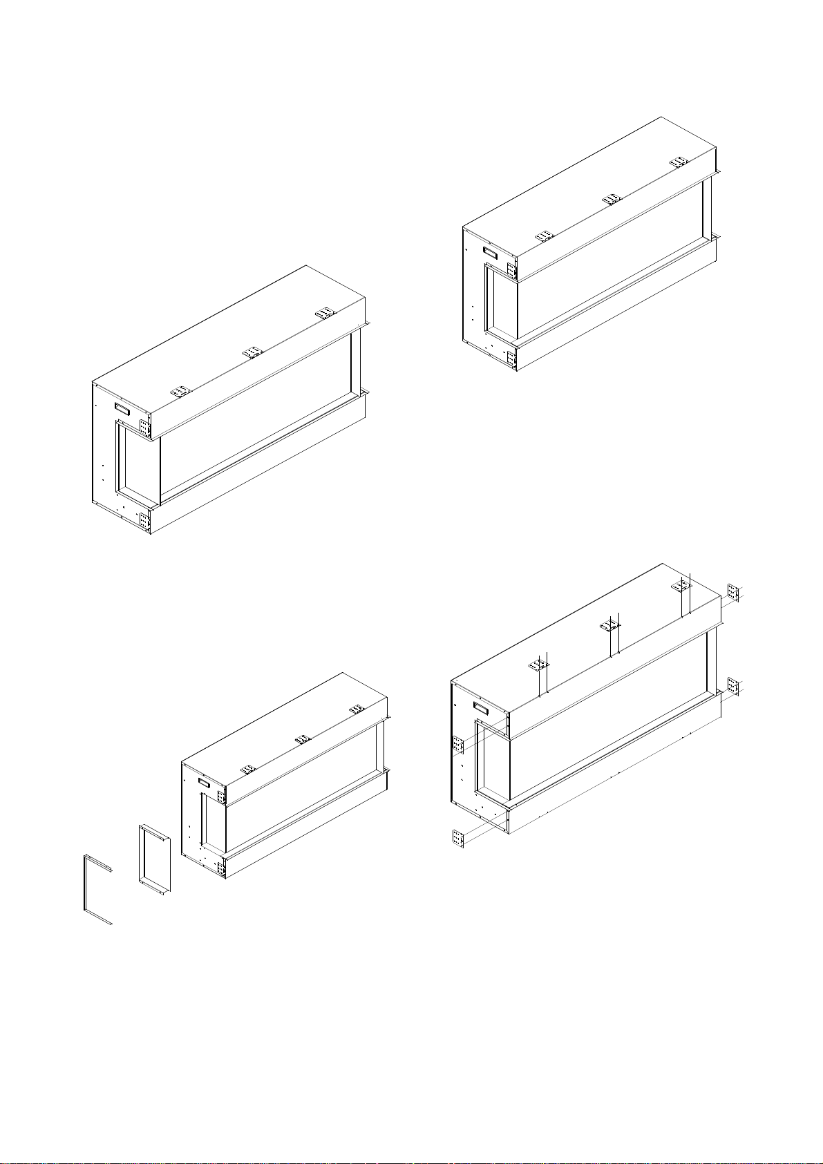
Installation for Front and right side
Viewing
1. To install the fireplace where the left side is
close to a wall, and you want to view the
fire from front and right side, take off the
fending panel on the right.
2. Unscrew 7screws on the right side that fix
the fending bar and panel and then take off
the fending bar and panel.
3. After the fending panel is removed, screw
back the bar.
4. Remove the framing plates from the
fireplace and fix them as the picture shows.
NOTE: After removing framing plates on the
left and right sides, screw back the screws.
15

5. Make an opening for the fireplace according
to requested measurement.
6. Insert the fireplace into the wall opening.
Drive the mounting screws into the frame
plates on the unit and the wall studs. To fix
the bottom of the fireplace and the wall
studs with the framing plates that you’ve
removed from left and right side of the
fireplace at STEP 4. Plug in and check if the
fireplace works.
7. After checking that the fireplace operates
properly, cover the glass panels with
protective plastic bag and install plywood or
drywall.
8. Decorate the plywood or drywall with
glazed tile, wallpaper, etc.
16
Installation for Front and Left Side
Viewing
1. Install the fireplace where the right side is
close to a wall, and you want to view the
fire from front and left side, take off the
fending panel on the left.
2. Unscrew 7 screws on the left side that fix
the fending bar and panel and then take off
the fending bar and panel.
3. After the fending panel is removed, screw
back the bar.
4. Remove the framing plates from the
fireplace and fix them as the picture shows.
NOTE: After removing the framing plates on
the left and right sides, screw back the
screws.
5. Make an opening for the fireplace according
to requested measurement.
17

6. Insert the fireplace into the wall opening.
Drive the mounting screws into the frame
plates on the unit and the wall studs. To fix
the bottom of the fireplace and the wall
studs with the framing plates that you’ve
removed from left and right side of the
fireplace at STEP 4. Plug in and check if the
fireplace works.
7. After checking that the fireplace operates
properly, cover the glass panels with
protective plastic bag and install plywood or
drywall.
8. Decorate the plywood or drywall with
glazed tile, wallpaper, etc.
18

MEDIA OPTIONS -The Bay Slim series models are shipped with a 10
piece birch media kit
1. Unscrew 2 screws and take off two brackets which
are fending the front glass panel.
Screws and brackets
2. After the brackets are removed, the front glass panel
will fall down automatically.
4. Installing the fire glass media. Pour the fire
glass media into the tray as shown below.
Feel free to use any combination of fire glass
media that you find most appealing.
3. Take off the front glass panel and put it in safe place.
5. Put back the front glass and screw back the bracket.
DESIGN-MEDIA-BIRCH-10PCE

OPERATION
The fireplace can be operated either by the switches located on the left bottom of the fireplace unit
or by supplied remote control.
Plug the fireplace into a 15 Amp wall socket.
MANUAL OPERATION
1. The main power ON/OFF switch in position O, the fireplace is OFF.
2. When main power ON/OFF switch is at position I, the fireplace is ready to use.
3. Press the button repeatedly to set the heater to desired heat setting. The heater indicator
LED will glow which shows the current heater settings.
a) RED 1465W HEAT OUTPUT
b) BLUE 750W HEAT OUTPUT
c) PURPLE AUTO MODE
AUTO MODE
Under this mode the heater will automatically turn ON at high heat setting 1465W heat output when
the room temperature drops below 22℃(72 ℉ ). When the room temperature is between
22-25℃(72-77℉) the heater output will switch to low heat setting 750W. When the room
temperature goes above 25℃(77℉) the heater will be turned off and the cycle will continue. The
LED indicator will be PURPLE in colour under this mode.
4. Flame effect: Press the button marked to adjust the flame brightness. The flame brightness
will cycle through –Low-Medium-High -OFF.
5. Mood light effect: Press the button marked to change the mood light colour.
NOTE: If operated at the Low heat setting, the fireplace will not provide as much heat output as in
the High heat setting, however the low setting will not require as much electrical power to operate.
To avoid overloading a circuit, do not plug the fireplace into a circuit that already has other
appliances working. When the fireplace is not in use switch off and unplug.
SAFETY CUT-OFF
l This appliance is fitted with a safety cut-off which will operate if the fireplace overheats (eg. Due
to blocked air vents). For safety reasons, the fireplace will NOT automatically reset.
l To reset the appliance, disconnect the appliance from the main supply for at least 10 minutes.
Reconnect the main power supply and put the main power switch to the ON position.
20

REMOTE CONTROL OPERATION
For remote to function make sure the heater is plugged in and main power switch located on the
bottom left hand side is at position I.
When operating the remote make sure you point the remote to the centre of the fireplace and make
sure each time you press the button. The buzzer inside the unit will beep once. It takes some time for
the receiver to respond to the transmitter. Do not PRESS the buttons more than once within two
seconds for correct operation.
Power on button: The power-on button at top left corner of the remote is the main ON/OFF
power button. This will turn off all the functions and the fireplace will be in standby mode.
DISPLAY ON/OFF button: Switching the fireplace flame and tray light ON/OFF. It has functions of
setting memory.
DISPLAY BLUE button: Adjust the blue color brightness of flame and tray.
DISPLAY YELLOW button: Adjust the yellow color brightness of flame and tray.
DISPLAY ORANGE button: Adjust the orange color brightness of flame and tray.
MOOD LIGHT ON/OFF button: Switching the mood light ON/OFF.
ADJUST button: Switching the color of the mood light.
FLASH button: Switches mood light into flash mode, this cycles through all mood light colors.
HEATER ON/OFF button: Switching the heater ON/OFF. It has functions of setting memory.
HIGHT button: Press the high button to switch the heater to high heat setting 1465W.
LOW button: Press the low button to switch the heater to low heat setting 750W.
TEMP. button: Press the TEMP. button to switch the heater to AUTO mode. Under this mode
the heater will operate in similar way as explained above for the manual operation.

INSTALLING WALL THERMOSTAT
WALL THERMOSTAT WIRING DIAGRAMS
Wire the wall thermostat prior to installing the fireplace.
WALL THERMOSTAT WIRING(24 VAC)
Install Wall Thermostat per instructions provided with kit and per the following information:
1. Turn off circuit breaker.
2. Remove cover plate located on the left side of appliance.
3. Pull the wire out and cut the inside thermostat. Connect the wires to the wall thermostat as
shown below. Follow instructions provided with wall switch kit.
22

This list contains replacement parts
NO
PART NUMBER
DESCRIPTION QTY
30-BAY SLIM 40-BAY SLIM 50-BAY SLIM
1 10701384 10701281 10701216 Front Clear Glass 1
2 10201505 ADJUSTABLE SCREW 2
3 3123010
FRONT CLEAR GLASS
BRACKET
2
4 10702266 10702267 10702268 BOTTOM TRAY GLASS 1
5 10702271 10701284B 10701219B BACK GLASS 1
6 10701385 SIDE CLEAR GLASS 2
7
601136B 601136B 601136B
LED STRIP FOR TRAY
AND FLAME
601141B 601141B 601141B
8 FLICKER ASSEMBLY 1
9 10101225 FLAME MOTOR 2
10 10104002 SWITCH 1
11 601036 MANUAL CONTROL 1
12 601092C CIRCUIT BOARD 1
13 602082B
BLOWER AND
HEATER ASSEMBLY
1
14 601002B REMOTE RECEIVER 1
15 WHOLE METAL BOX 1
16 10125019 10125021 10125022 TOP LED STRIP 1
17 10105063 REMOTE CONTROL 1
REPLACEMENT PARTS
*# 16 and 17 are not shown in the exploded view.
23
3089504E 3151505 3123505C

NO
PART NUMBER
DESCRIPTION QTY
60-BAY SLIM 72-BAY SLIM
1 10701217 10701218 Front Clear Glass 1
2 10201505 ADJUSTABLE SCREW 2
3 3123010
FRONT CLEAR GLASS
BRACKET
2
4 10702269 10702270 BOTTOM TRAY GLASS 1
5 10701220B 10701221B BACK GLASS 1
6 10701385 SIDE CLEAR GLASS 2
7
601136B 601137B
LED STRIP FOR TRAY
AND FLAME
601141B 601141B
8 FLICKER ASSEMBLY 1
9 10101225 FLAME MOTOR 2
10 10104002 SWITCH 1
11 601036 MANUAL CONTROL 1
12 601092C CIRCUIT BOARD 1
13 602082B
BLOWER AND HEATER
ASSEMBLY
1
14 601002B REMOTE RECEIVER 1
15 WHOLE METAL BOX 1
16 10125023 10125024 TOP LED STRIP 1
17 10105063 REMOTE CONTROL 1
* #16 and 17 are not shown in exploded view
This list contains replacement parts
24
3124505C 3125505C

EXPLODED VIEW
25

Wiring Diagram
26

TROUBLE SHOOTING
PROBLEM POSSIBLE CAUSE SOLUTION
Dim or no flame Flame LED’s are burnt out Inspect the LED’s and replace them if
necessary.
Ember bed is not
glowing or dimming
Ember LED’s are burnt out Inspect the ember bed LED’s and
replace them if necessary.
Appliance has overheated and
safety device has caused the
thermal switch to disconnect
Turn off the main switch, allow
appliance to cool for 10 minutes, then
turn it on.
House circuit breaker has
tripped
Reset house circuit breaker.
Appliance turns off and
will not turn on
Appliance’s fuse has blown Replace the fuse.
Appliance is not plugged into an
electrical outlet
Check plug and plug in.
Appliance has overheated and
safety device has caused the
thermal switch to disconnect
Turn off the main switch, allow
appliance to cool for 10 minutes, then
turn it on.
Appliance will not come
on when switch is
flipped to ON
Circuit board is burnt out Inspect the circuit board and replace
it if necessary.
No warm air coming out
of appliance
Heater is burnt out Inspect the burner and heater
assembly and replace it if necessary.
Flame sputters Flame motor is defective. Call a qualified service technician and
replace flame motor.
Remote Control does
not work.
Low batteries.
Unit switch in “O” position.
Replace AAA batteries in remote
control.
Turn the switch in “I” position.
Flame is fixed. Wiring may be loose or the
flame motor may be defective.
27

SERVICE HISTORY
This heater must be serviced annually depending on usage.
Date Dealer
Name
Service
technician Name
Service Performed Special Concerns
NOTES:
28

29