
TT 808-AS
PROFESSIONAL ACTIVE SUBWOOFER
OWNER’S MANUAL
MANUALE UTENTE


3
CONTENTS
ENGLISH
1 SAFETY PRECAUTIONS AND GENERAL INFORMATION ����������������������������������������������������������������������������������������������������������������� 4
2 DESCRIPTION ������������������������������������������������������������������������������������������������������������������������������������������������������������������������������������ 6
3 REAR PANEL FEATURES AND CONTROLS ��������������������������������������������������������������������������������������������������������������������������������������� 7
4 CONNECTION ������������������������������������������������������������������������������������������������������������������������������������������������������������������������������������ 8
5 INSTALLATION ����������������������������������������������������������������������������������������������������������������������������������������������������������������������9
6� FLOOR CONFIGURATIONS ��������������������������������������������������������������������������������������������������������������������������������������������������10
7� SUSPENDED CONFIGURATIONS �����������������������������������������������������������������������������������������������������������������������������������������11
8� TROUBLESHOOTING �����������������������������������������������������������������������������������������������������������������������������������������������������������15
ITALIANO
1 AVVERTENZE PER LA SICUREZZA E INFORMAZIONI GENERALI ������������������������������������������������������������������������������������������������� 16
2 DESCRIZIONE ���������������������������������������������������������������������������������������������������������������������������������������������������������������������������������� 18
3 PANNELLO POSTERIORE - FUNZIONI E CONTROLLI �������������������������������������������������������������������������������������������������������������������� 19
4 CONNESSIONI ��������������������������������������������������������������������������������������������������������������������������������������������������������������������������������� 20
5 INSTALLAZIONE �����������������������������������������������������������������������������������������������������������������������������������������������������������������21
6� CONFIGURAZIONI A TERRA ������������������������������������������������������������������������������������������������������������������������������������������������ 22
6� CONFIGURAZIONI IN SOSPENSIONE ����������������������������������������������������������������������������������������������������������������������������������23
7 RISOLUZIONE DEI PROBLEMI ���������������������������������������������������������������������������������������������������������������������������������������������27
DIMENSIONS / DIMENSIONI ��������������������������������������������������������������������������������������������������������������������������������������������������������28
SPECIFICATIONS/SPECIFICHE �������������������������������������������������������������������������������������������������������������������������������������������������������29
4
EN
1. SAFETY PRECAUTIONS AND GENERAL INFORMATION
The symbols used in this document give notice of important operating instructions
and warnings which must be strictly followed�
CAUTION
Important operating instructions:
explains hazards that could damage a
product, including data loss
WARNING
Important advice concerning the use of
dangerous voltages and the potential
risk of electric shock, personal injury or
death�
IMPORTANT NOTES
Helpful and relevant information
about the topic
SUPPORTS, TROLLEYS
AND CARTS
Information about the use of supports,
trolleys and carts� Reminds to move with
extreme caution and never tilt�
WASTE DISPOSAL
This symbol indicates that this product
should not be disposed with your
household waste, according to the
WEEE directive (2012/19/EU) and your
national law�
IMPORTANT NOTES
This manual contains important information about the correct and safe use of the
device� Before connecting and using this product, please read this instruction manual
carefully and keep it on hand for future reference� The manual is to be considered
an integral part of this product and must accompany it when it changes ownership
as a reference for correct installation and use as well as for the safety precautions�
RCF S�p�A� will not assume any responsibility for the incorrect installation and / or
use of this product�
SAFETY PRECAUTIONS
1� All the precautions, in particular the safety ones, must be read with special
attention, as they provide important information�
2� Power supply from mains
a� The mains voltage is sufficiently high to involve a risk of electrocution; install
and connect this product before plugging it in�
b� Before powering up, make sure that all the connections have been made
correctly and the voltage of your mains corresponds to the voltage shown on
the rating plate on the unit, if not, please contact your RCF dealer�
c� The metallic parts of the unit are earthed through the power cable� An apparatus
with CLASS I construction shall be connected to a mains socket outlet with a
protective earthing connection�
d� Protect the power cable from damage; make sure it is positioned in a way that
it cannot be stepped on or crushed by objects�
e� To prevent the risk of electric shock, never open this product: there are no parts
inside that the user needs to access�
f� Be careful: in the case of a product supplied by manufacturer only with
POWERCON connectors and without a power cord, jointly to POWERCON
connectors type NAC3FCA (power-in) and NAC3FCB (power-out), the following
power cords compliant to national standard shall be used:
- EU: cord type H05VV-F 3G 3x2�5 mm2 - Standard IEC 60227-1
- JP: cord type VCTF 3x2 mm2; 15Amp/120V~ - Standard JIS C3306
- US: cord type SJT/SJTO 3x14 AWG; 15Amp/125V~ - Standard ANSI/UL 62
3� Make sure that no objects or liquids can get into this product, as this may cause
a short circuit� This apparatus shall not be exposed to dripping or splashing� No
objects filled with liquid, such as vases, shall be placed on this apparatus� No naked
sources (such as lighted candles) should be placed on this apparatus�
4� Never attempt to carry out any operations, modifications or repairs that are not
expressly described in this manual�
Contact your authorized service centre or qualified personnel should any of the
following occur:
- The product does not function (or functions in an anomalous way)�
- The power cable has been damaged�
- Objects or liquids have got in the unit�
- The product has been subject to a heavy impact�
5� If this product is not used for a long period, disconnect the power cable�
6� If this product begins emitting any strange odours or smoke, switch it off
immediately and disconnect the power cable�
7� Do not connect this product to any equipment or accessories not foreseen�
For suspended installation, only use the dedicated anchoring points and do not try
to hang this product by using elements that are unsuitable or not specific for this
purpose� Also check the suitability of the support surface to which the product is
anchored (wall, ceiling, structure, etc�), and the components used for attachment
(screw anchors, screws, brackets not supplied by RCF etc�), which must guarantee
the security of the system / installation over time, also considering, for example, the
mechanical vibrations normally generated by transducers�
To prevent the risk of falling equipment, do not stack multiple units of this product
unless this possibility is specified in the user manual�
8� RCF S�p�A� strongly recommends this product is only installed by
professional qualified installers (or specialised firms) who can ensure
correct installation and certify it according to the regulations in force�
The entire audio system must comply with the current standards and
regulations regarding electrical systems�
9� Supports, trolleys and carts�
The equipment should be only used on supports, trolleys and carts,
where necessary, that are recommended by the manufacturer� The
equipment / support / trolley / cart assembly must be moved with
extreme caution� Sudden stops, excessive pushing force and uneven
floors may cause the assembly to overturn� Never tilt the assembly�
10� There are numerous mechanical and electrical factors to be considered when
installing a professional audio system (in addition to those which are strictly
acoustic, such as sound pressure, angles of coverage, frequency response, etc�)�
11� Hearing loss�
Exposure to high sound levels can cause permanent hearing loss� The acoustic
pressure level that leads to hearing loss is different from person to person and
depends on the duration of exposure� To prevent potentially dangerous exposure
to high levels of acoustic pressure, anyone who is exposed to these levels should
use adequate protection devices� When a transducer capable of producing high
sound levels is being used, it is therefore necessary to wear ear plugs or protective
earphones� See the manual technical specifications to know the maximum sound
pressure level�
OPERATING PRECAUTIONS
- Place this product far from any heat sources and always ensure an adequate air
circulation around it�
- Do not overload this product for a long time�
- Never force the control elements (keys, knobs, etc�)�
- Do not use solvents, alcohol, benzene or other volatile substances for cleaning
the external parts of this product�
IMPORTANT NOTES
To prevent the occurrence of noise on line signal cables, use screened cables only
and avoid putting them close to:
- Equipment that produces high-intensity electromagnetic fields
- Power cables
- Loudspeaker lines

5
EN
1. SAFETY PRECAUTIONS AND GENERAL INFORMATION
WARNING! CAUTION! To prevent the risk of fire or electric
shock, never expose this product to rain or humidity�
WARNING! To prevent electric shock hazard, do not connect to
mains power supply while grille is removed
WARNING! to reduce the risk of electric shock, do not disassemble
this product unless you are qualified� Refer servicing to qualified service
personnel�
CORRECT DISPOSAL OF THIS PRODUCT
This product should be handed over to an authorized collection
site for recycling waste electrical and electronic equipment (EEE)�
Improper handling of this type of waste could have a possible
negative impact on the environment and human health due to
potentially hazardous substances
that are generally associated with EEE� At the same time, your
cooperation in the correct disposal of thisproduct will contribute to the
effective usage of natural resources� For more information about where
you can drop off your waste equipment for recycling, please contact
your local city office, waste authority or your household waste disposal
service�
CARE AND MAINTENANCE
To ensure a long-life service, this product should be used following these advices:
- If the product is intended to be set up outdoors, be sure it is under cover and
protected to rain and moisture�
- If the product needs to be used in a cold environment, slowly warm up the
voice coils by sending a low-level signal for about 15 minutes before sending
high-power signals�
- Always use a dry cloth to clean the exterior surfaces of the speaker and always
do it when the power is turned off�
CAUTION: to avoid damaging the exterior finishes do not use
cleaning solvents or abrasives�
WARNING! CAUTION! For powered speakers, do cleaning
only when the power is turned off�
RCF S�p�A� reserves the right to make changes without
prior notice to rectify any errors and / or omissions�
Always refer to the latest version of the manual on
www�rcf�it�

6
EN
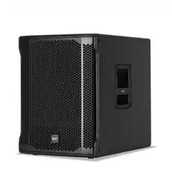
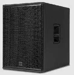
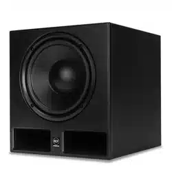
TT 808-AS - PROFESSIONAL ACTIVE SUBWOOFER
TT 808-AS is a compact low-profile high-performance active subwoofer� It features two vented-loaded 8” cone woofers powered by a 1000 Watts
two-channel amplifier (one for each woofer) on a baltic birch plywood cabinet painted with black polyurea�
Management and tuning are available via RDNet software or using the two preset buttons, a polarity button, and a variable delay accessible from
the back panel� The cabinet features rubber feet on two sides and two threaded pole-mounts for horizontal and vertical placement� Two stabilizing
brackets make the vertical placement stable and firm�
TT 808-AS can be used stand-alone, in subwoofer arrays, or as the low-frequency complement for TT 515-A speaker�
2. DESCRIPTION
TT 808-AS
2000 Watt
2 X 8” Vented Woofers
19,5 Kg (43 lbs)

7
EN
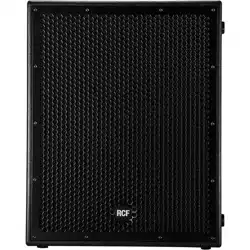
3. REAR PANEL FEATURES AND CONTROLS
1
FEMALE XLR INPUTS (BAL/UNBAL) The system accepts XLR input connectors�
2
MALE XLR SIGNAL OUTPUT The output XLR connector provides a loop through
for speakers daisy chaining� The balanced connector is connected in parallel and can be
used to send the audio signal to other amplified speakers, recorders or supplementary
amplifiers�
3
SYSTEM VOLUME KNOB
4
SIGNAL / LIMITER LED The LED light is green when a signal is applied to the
speaker� It turns RED when the speaker compressor activates�
5
POWER LED This green led is ON when the speaker is connected to the main power
supply�
6
LINK LED This LED turns on when the speaker is connected to RDNet�
7
ACTIVE LED This LED blinks when the speaker is transmitting data over RDNet�
8
RDNET DATA INPUT AND DATA LINK The RDNET IN/OUT PLUG SECTION
features etherCON connectors for the RCF RDNet protocol� This allows the user to
completely control the speaker using the RDNet software�
9
LP 90 Hz / TT 515-A When this button is released the subwoofer works with
its standard subwoofer configuration (40 Hz - 90 Hz)� When this button is pressed the
subwoofer automatically sets its alignment with RCF TT 515-A; at the same time the
button “FLAT / HIGH PASS“ on TT 515-A has to be pressed (on “HIGH PASS” mode)�
10
BYPASS / LOCAL SETUP When pressed, the setup is loaded from the internal
memory that only RDNet can write� Every time the speaker is turned on, the last stored
configuration is applied�
When the button is released, the speaker uses its local setup and will not remember its last
RDNet setup when turned on again�
11
AC POWER INPUT Powercon locking 3-pole AC mains�
12
AC OUTPUT LINK Sends the AC power to another speaker�
Power link: 100-120V~16 A MAX 1600W l 200-240V~16 A MAX 3500W�
WARNING! CAUTION! Loudspeaker connections should be
only made by qualified and experienced personnel having the technical
know-how or enough specific instructions (to ensure that connections are
made correctly) in order to prevent any electrical danger�
To prevent any risk of electric shock, do not connect loudspeakers when
the amplifier is switched on�
Before turning the system on, check all connections and make sure there
are no accidental short circuits�
The entire sound system shall be designed and installed in compliance
with the current local laws and regulations regarding electrical systems�
11 12
1
2
3
8
9
10
4 6
5 7
8
EN
4. CONNECTIONS
The connectors must be wired according to the standards specified by the AES (Audio Engineering Society)�
BEFORE CONNECTING THE SPEAKER
On the rear panel you will find all the controls, signal and power inputs� At first verify the voltage label applied to the rear panel (115 Volt or 230
Volt)� The label indicates the right voltage� If you read a wrong voltage on the label or if you can’t find the label at all, please call your vendor or
authorized RCF SERVICE CENTRE before connecting the speaker� This fast check will avoid any damage�
In case of need of changing the voltage please call your vendor or authorized RCF SERVICE CENTRE� This operation requires the replacement of
the fuse value and is reserved to an RCF SERVICE CENTRE�
BEFORE TURNING ON THE SPEAKER
You can now connect the power supply cable and the signal cable� Before turning on the speaker make sure the volume control is at the minimum
level (even on the mixer output)� It is important that the mixer is already ON before turning on the speaker� This will avoid damages to the speaker
and noisy “bumps” due to turning on parts on the audio chain� It is a good practice to always turn on the speakers at last and turning them off
immediately after their use� You can now turn ON the speaker and adjust the volume control to a proper level�
PROTECTIONS
ART Series active speakers are equipped with a complete system of protection circuits� The circuit is acting very gently on audio signal, controlling
level and maintaining distortion at acceptable level�
VOLTAGE SETUP (RESERVED TO THE RCF SERVICE CENTRE)
200-240 Volt, 50 Hz SETUP:
FUSE VALUE T 3�15 A L 250V
100-120 Volt, 60 Hz SETUP:
FUSE VALUE T6�3 A L 250V
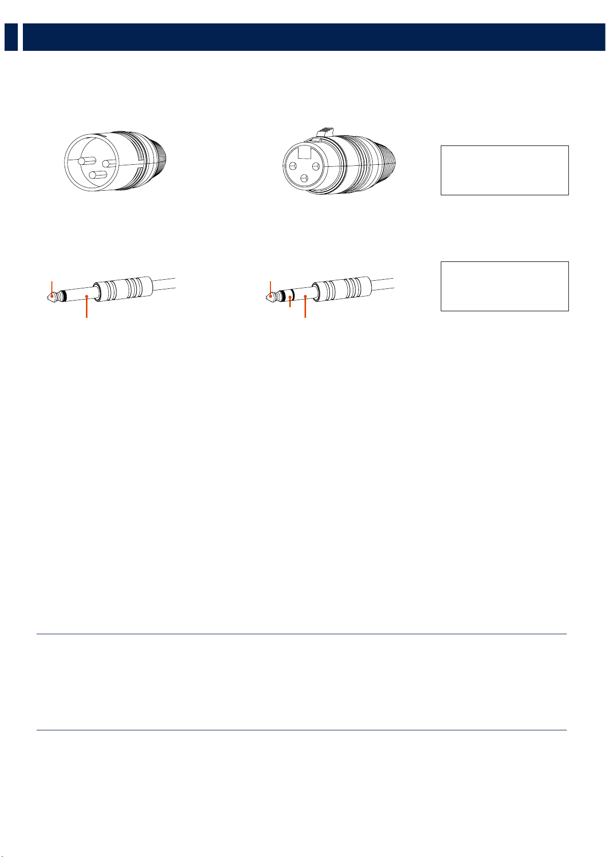
MALE XLR CONNECTOR
Balanced wiring
22
11
33
FEMALE XLR CONNECTOR
Balanced wiring
22
11
33
TRS CONNECTOR
Balanced mono wiring
TIPTIP
RINGRING
SLEEVESLEEVE
TRS CONNECTOR
Unbalanced mono wiring
TIPTIP
SLEEVESLEEVE
PIN 1 = GROUND (SHIELD)
PIN 2 = HOT (+)
PIN 3 = COLD (-)
SLEEVE = GROUND (SHIELD)
TIP = HOT (+)
RING = COLD (-)

9
EN
5. INSTALLATION
The Subowoofer RCF TT 808-AS can be used either in horizontal or vertical position�
HORIZONTAL CONFIGURATION
(setup with RCF TT 515-A)
VERTICAL CONFIGURATION
(setup with RCF TT 515-A)
When used on vertical position, slide the two plastic plates
on the bottom of the speaker for a better stability and safety�
FLYING POINTS
TT 808-AS can be hanged horizontally or vertically; 4 x M10 flying points are available on two sides (two each side)�
When TT 808-AS is used together with TT 515-A remeber to press both the following buttons:
on TT 808-AS
on TT 515-A
MAX
1300 mm
MAX
750 mm
CAUTION! When pole mounting a TT 515-A over TT 808-AS, the maximum pole lenght must be 1300mm (for the horizontal
configuration) and 750mm (for the vertical configuration)�

10
EN
6. FLOOR CONFIGURATIONS
Using the specific preset on RdNet, TT 808-AS can be used in cardioid configuration, either in horizontal and vertical position�
2 x TT 808-AS
CARDIOID CONFIGURATION
HORIZONTAL SETUP
2 x TT 808-AS
CARDIOID CONFIGURATION
VERTICAL SETUP
3 x TT 808-AS
CARDIOID CONFIGURATION
HORIZONTAL SETUP
3 x TT 808-AS
CARDIOID CONFIGURATION
VERTICAL SETUP
11
EN
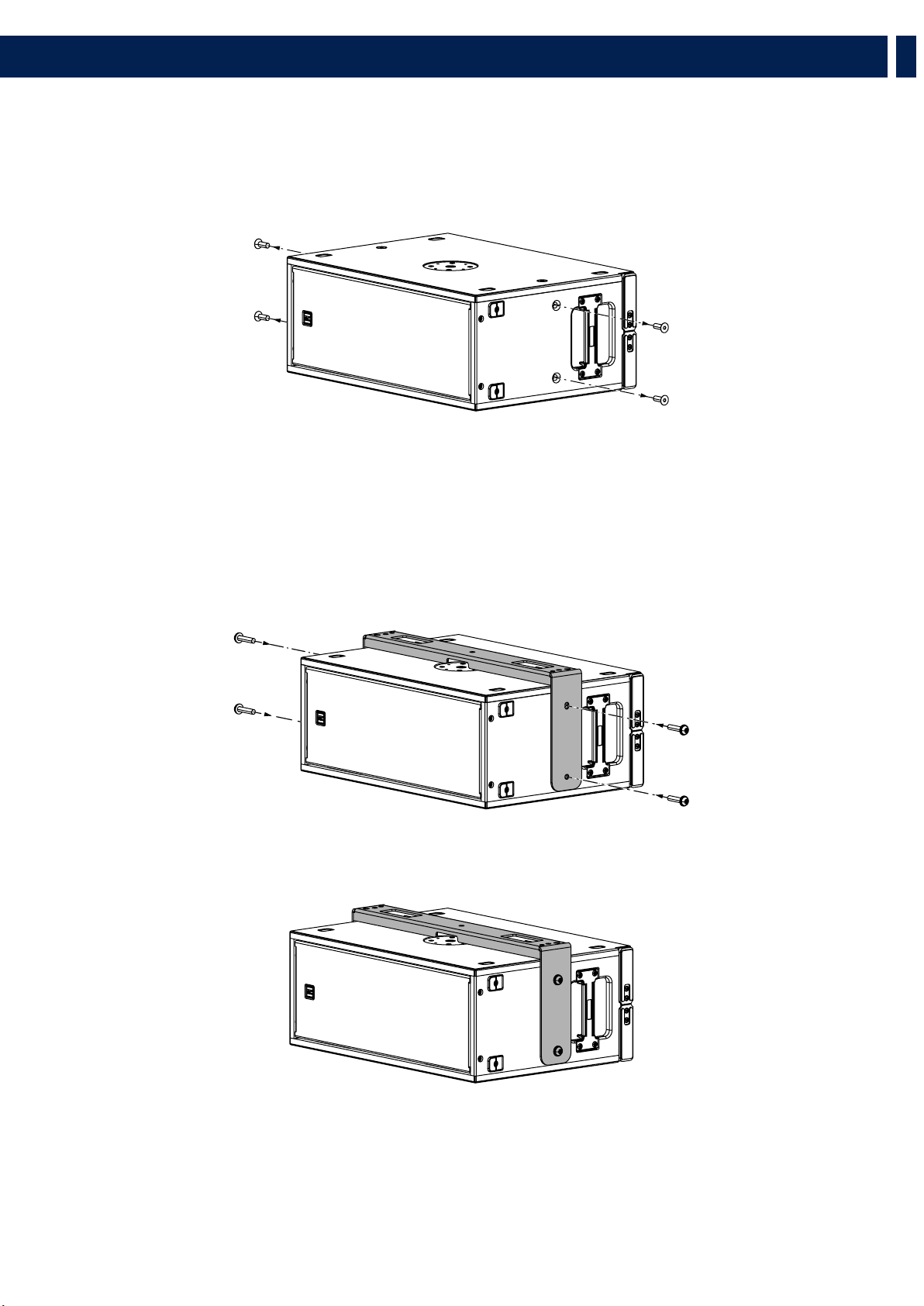
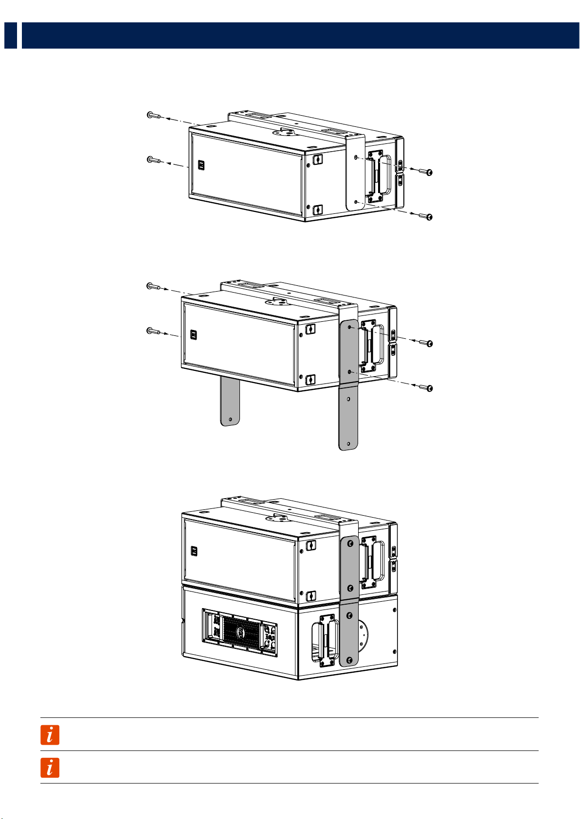
7. SUSPENDED CONFIGURATIONS
2� Place the bracket over the speaker and screw it to the cabinet with the four M10 screws (and washers) provided�
With the use of the vertical bracket V-BR TT 808 it is possible to suspend one or two subwoofers TT 808-AS�
1� Remove the four M10 screws from both the sides of the speakers�

12
EN
7. SUSPENDED CONFIGURATIONS
An additional subwoofer TT 808-AS can be placed below the first one with the use of two linking brackets�
1� Remove the four M10 screws from both the sides of the speakers�
2� Place the linking brackets on both sides (as shown in the picture) and screw them to the cabinet with the same M10 screws (and washers)
premoved earlier�
3� Place the second subwoofer in cardioid configuration and screw the bracket to it with the M10 screws provided�
NOTE: The same operations must be done on both sides of the speaker
NOTE: A maximum of two TT 808-AS can be suspended with the vertical bracket�

13
EN
7. SUSPENDED CONFIGURATIONS
With the use of the LINK BAR FL-B LINK TT 515 it is possible to suspend a TT 515-A below a single suspended TT 808-AS�
1� Loosen the M10 upper screw and completely remove the lower M10 screw�
2� Place the LINK BARS on both sides and letting the upper screw pass throug the circular bottonhole; then screw back the lower screw (do not
tighten the screw yet)�
3� Pull down the bracket and tighten both the upper and lower screw�

14
EN
4� Place a TT 515-A between the two brackets and fix it by placing the two knobs or bolts provided�
5� Choose the right inclination and tighten the bolts or knobs�
NOTE: The same operations must be done on both sides of the speaker
NOTE: This configuration can be only done with one TT 808-AS and one TT 515-A�
7. SUSPENDED CONFIGURATIONS

15
EN
8. TROUBLESHOOTING
THE SPEAKER DOESN’T TURN ON
Make sure the speaker is switched on and connected to an active AC power
THE SPEAKER IS CONNECTED TO AN ACTIVE AC POWER BUT DOESN’T TURN ON
Make sure the power cable is intact and connected correctly�
THE SPEAKER IS ON BUT DOESN’T MAKE ANY SOUND
Check if the signal source is sending correctly and if the signal cables are not damaged�
THE SOUND IS DISTORTED AND THE OVERLOAD LED BLINKS FREQUENTLY
Turn down the output level of the mixer�
THE SOUND IS VERY LOW AND HISSING
The source gain or the output level of the mixer might be too low�
THE SOUND IS HISSING EVEN AT PROPER GAIN AND VOLUME
The source might send a low quality or noisy signal
HUMMING OR BUZZING NOISE
Check out the AC grounding and all the equipments connected to the mixer input including cables and connectors�
WARNING! to reduce the risk of electric shock, do not disassemble this product unless you are qualified� Refer servicing
to qualified service personnel�

16
IT
1. AVVERTENZE PER LA SICUREZZA E INFORMAZIONI GENERALI
I simboli utilizzati in questo documento notificano importanti istruzioni operative e
avvertimenti che devono essere seguiti attentamente�
CAUTELA
Importante istruzione operativa: notifica
un pericolo che potrebbe danneggiare il
prodotto, compresa la perdita di dati
ATTENZIONE
Avvertimento importante riguardante l’uso
di voltaggi pericolosi e il potenziale rischio
di shock elettrico, lesioni personali o morte�
NOTE IMPORTANTI
Informazioni utili e rilevanti sull’argomento
SUPPORTI,
TROLLEY E
CARRRELLI
Informazioni riguardanti l’utilizzo di
supporti, trolley e carrelli� Suggerisce di
muovere con estrema cautela e di non
inclinare il carico�
SMALTIMENTO
Questo simbolo indica che il prodotto non
deve essere smaltito con i rifiuti ordinari,
così come indicato nella direttiva WEEE
(2012/19/EU) e nelle normative nazionali
in vigore�
NOTE IMPORTANTI
Questo manuale contiene informazioni importanti sull’uso corretto e sicuro del
dispositivo� Prima di collegare e utilizzare questo prodotto, leggere attentamente
questo manuale di istruzioni e tenerlo a portata di mano per riferimenti futuri�
Il manuale deve essere considerato parte integrante di questo prodotto e deve
accompagnarlo in caso di cambio proprietà come riferimento per la corretta
installazione e utilizzo nonché per le precauzioni di sicurezza� RCF S�p�A� non si
assume alcuna responsabilità per l’installazione e / o l’uso errati di questo prodotto�
PRECAUZIONI DI SICUREZZA
1� Tutte le precauzioni, in particolare quelle di sicurezza, devono essere lette con
particolare attenzione, in quanto forniscono informazioni importanti�
2� Alimentazione principale da rete elettrica
a� La tensione di rete è sufficientemente elevata da comportare un rischio di
folgorazione; installare e collegare questo prodotto prima di collegarlo�
b� Prima di accendere, assicurarsi che tutti i collegamenti siano stati eseguiti
correttamente e che la tensione della rete corrisponda alla tensione indicata
sulla targhetta dei dati sull’unità, in caso contrario, contattare il rivenditore RCF�
c� Le parti metalliche dell’unità sono messe a terra attraverso il cavo di
alimentazione� Un apparecchio con costruzione di CLASSE I deve essere
collegato a una presa di corrente con un collegamento di terra di protezione�
d� Proteggere il cavo di alimentazione da danni; assicurarsi che sia posizionato in
modo tale da non poter essere calpestato o schiacciato da oggetti�
e� Per evitare il rischio di scosse elettriche, non aprire mai questo prodotto: non
sono previste parti interne alle quali l’utente debba accedere�
f� Fare attenzione: nel caso di un prodotto provvisto solo di connettori POWERCON
e senza cavo di alimentazione, congiuntamente ai connettori POWERCON tipo
NAC3FCA (alimentazione) e NAC3FCB (alimentazione), devono essere usati i
seguenti cavi di alimentazione conformi alla norma nazionale:
- EU: cavo di tipo H05VV-F 3G 3x2�5 mm2 - Standard IEC 60227-1
- JP: cavo di tipo VCTF 3x2 mm2; 15Amp/120V~ - Standard JIS C3306
- US: cavo di tipo SJT/SJTO 3x14 AWG; 15Amp/125V~ - Standard ANSI/UL 62
3� Assicurarsi che nessun oggetto o liquido penetri in questo prodotto poiché ciò
potrebbe causare un corto circuito� Questo apparecchio non deve essere esposto a
gocciolamenti o spruzzi� Nessun oggetto riempito di liquido, come vasi, deve essere
posizionato su questo apparecchio� Nessuna fiamma libera (come candele accese)
deve essere posizionata su questo apparecchio�
4� Non tentare mai di eseguire operazioni, modifiche o riparazioni non
espressamente descritte nel presente manuale�
Contattare il centro di assistenza autorizzato o personale qualificato qualora si
verifichi una delle seguenti condizioni:
- Il prodotto non funziona (o funziona in modo anomalo)�
- Il cavo di alimentazione è stato danneggiato�
- Oggetti o liquidi sono entrati nell’unità�
- Il prodotto ha subìto un forte urto�
5� Se questo prodotto non viene utilizzato per un lungo periodo, scollegare il cavo
di alimentazione�
6� Se questo prodotto inizia a emettere strani odori o fumo, spegnerlo
immediatamente e scollegare il cavo di alimentazione�
7� Non collegare questo prodotto ad apparecchiature o accessori non previsti�
Per l’installazione sospesa, utilizzare solo i punti di ancoraggio dedicati e non
tentare di appendere questo prodotto utilizzando elementi non idonei o non
specifici per questo scopo� Verificare inoltre l’idoneità della superficie di supporto a
cui è ancorato il prodotto (parete, soffitto, struttura, ecc�) a dei componenti utilizzati
per il fissaggio (tasselli, viti, staffe non fornite da RCF ecc�) che devono garantire
sicurezza del sistema / installazione nel tempo, anche considerando, ad esempio, le
vibrazioni meccaniche normalmente generate dai trasduttori�
Per evitare il rischio di caduta dell’apparecchiatura, non impilare più unità di questo
prodotto a meno che questa possibilità non sia specificata nel manuale dell’utente�
8�RCF S�p�A� raccomanda vivamente che questo prodotto sia installato
solo da installatori professionisti qualificati (o aziende specializzate)
che possono garantire la corretta installazione e certificarlo secondo le
normative vigenti�
L’intero sistema audio deve essere conforme agli standard e alle
normative vigenti in materia di sistemi elettrici�
9� Supporti, trolley e carrelli�
L’apparecchiatura deve essere utilizzata, ove necessario, solo su
supporti, trolley e carrelli consigliati dal produttore� L’apparecchiatura /
supporto / carrello deve essere spostata con estrema cautela� Arresti
improvvisi, eccessiva spinta e pavimenti irregolari possono causarne il
ribaltamento� Non inclinare mai�
10� Vi sono numerosi fattori meccanici ed elettrici da considerare quando si
installa un sistema audio professionale (oltre a quelli strettamente acustici, come la
pressione del suono, gli angoli di copertura, la risposta in frequenza, ecc�)�
11� Perdita dell’udito�
L’esposizione a livelli sonori elevati può causare la perdita permanente dell’udito�
Il livello di pressione acustica che porta alla perdita dell’udito è diverso da persona
a persona e dipende dalla durata dell’esposizione� Per prevenire un’esposizione
potenzialmente pericolosa a livelli elevati di pressione acustica, chiunque sia
esposto a questi livelli dovrebbe usare adeguati dispositivi di protezione� Quando
viene utilizzato un trasduttore in grado di produrre alti livelli sonori, è quindi
necessario indossare tappi per le orecchie o cuffie protettive� Vedere le specifiche
tecniche del manuale per conoscere il livello massimo di pressione sonora�
PRECAUZIONI OPERATIVE
- Posizionare questo prodotto lontano da qualsiasi fonte di calore e garantire
sempre un’adeguata circolazione dell’aria attorno ad esso�
- Non sovraccaricare questo prodotto per molto tempo�
- Non forzare mai gli elementi di controllo (tasti, manopole, ecc�)�
- Non utilizzare solventi, alcool, benzene o altre sostanze volatili per pulire le
parti esterne di questo prodotto�
NOTE IMPORTANTI
Per evitare il verificarsi di disturbi sui cavi di segnale in linea, utilizzare solo cavi
schermati ed evitare di avvicinarli a:
- Apparecchiature che producono campi elettromagnetici ad alta
intensità
- Cavi di alimentazione
- Linee di altoparlanti
17
IT
1. AVVERTENZE PER LA SICUREZZA E INFORMAZIONI GENERALI
ATTENZIONE! CAUTELA! Per evitare il rischio di incendi o
scosse elettriche, non esporre mai questo prodotto a pioggia o umidità�
ATTENZIONE! Per evitare il rischio di scosse elettriche, non collegare
all’alimentazione di rete mentre la griglia è rimossa�
WARNING! Per ridurre il rischio di scosse elettriche, non smontare
questo prodotto se non si è qualificati� Per l’assistenza rivolgersi a personale
di assistenza qualificato
SMALTIMENTO CORRETTO DI QUESTO PRODOTTO
Questo prodotto deve essere consegnato a un sito di raccolta
autorizzato per il riciclaggio di apparecchiature elettriche ed
elettroniche (AEE)� Una manipolazione impropria di questo tipo di
rifiuti potrebbe avere un possibile impatto negativo sull’ambiente
e sulla salute umana a causa di sostanze potenzialmente pericolose che
sono generalmente associati alle AEE� Allo stesso tempo, la vostra
collaborazione per il corretto smaltimento di questo prodotto
contribuirà all’utilizzo efficace delle risorse naturali� Per ulteriori
informazioni su dove sia possibile scaricare le attrezzature per il
riciclaggio, si prega di contattare l’ufficio comunale locale, l’autorità
competente per i rifiuti o il servizio di smaltimento dei rifiuti domestici
�
CURA E MANUTENZIONE
Per garantire un servizio di lunga durata, questo prodotto deve essere utilizzato seguendo
questi consigli:
- Se il prodotto deve essere installato all’aperto, assicurarsi che sia coperto e
protetto da pioggia e umidità�
- Se il prodotto deve essere utilizzato in un ambiente freddo, riscaldare lentamente
le bobine vocali inviando un segnale di basso livello per circa 15 minuti prima
di inviare segnali ad alta potenza�
- Utilizzare sempre un panno asciutto per pulire le superfici esterne
dell’altoparlante e farlo sempre quando l’alimentazione è spenta
CAUTELA! Per evitare di danneggiare le finiture esterne non
utilizzare solventi per la pulizia o abrasivi�
ATTENZIONE! CAUTELA! Per gli altoparlanti alimentati,
eseguire la pulizia solo quando l’alimentazione è spenta�
RCF S�p�A� si riserva il diritto di apportare modifiche
senza preavviso per rettificare eventuali errori e/o
omissioni�
Fare sempre riferimento all’ultima versione del
manuale su www�rcf�it�

18
IT
TT 808-AS - SUBWOOFER PROFESSIONALE ATTIVO
TT 808-AS è un subwoofer attivo compatto e di alta prestazione� È dotato di due woofer ventilati da 8” alimentati da un amplificatore a due canali
da 1000 Watt (uno per ogni woofer) su un cabinet in multistrato di betulla del Baltico verniciato con poliurea nera�
La gestione e la sintonizzazione sono disponibili tramite il software RDNet o utilizzando i due pulsanti di preselezione accessibili dal pannello
posteriore: un pulsante di polarità e un ritardo variabile� Il cabinet è dotato di piedini in gomma su due lati e due supporti filettati per il
posizionamento orizzontale e verticale� Due staffe stabilizzatrici rendono stabile e sicuro il posizionamento verticale�
TT 808-AS può essere utilizzato da solo, in array di subwoofer o come complemento a bassa frequenza per il diffusore TT 515-A�
2. DESCRIZIONE
TT 808-AS
2000 Watt
2 X 8” Woofer ventilati
19,5 Kg (43 lbs)

19
IT
3. PANNELLO POSTERIORE - FUNZIONI E CONTROLLI
1
INGRESSO SEGNALE XLR FEMMINA (BAL/UNBAL) Il sistema accetta in ingresso
connettori XRL�
2
USCITA SEGNALE XLR MASCHIO Il connettore XLR di loop del segnale permette
la connessione a catena di più diffusori� Il connettore bilanciato è connesso in parallelo e
può essere usato per inviare il segnale audio ad altri diffusori, registratori o amplificatori
supplementari�
3
MANOPOLA DEL VOLUME
4
LED SIGNAL / LIMITER Il LED si illumina di verde quando un segnale viene
trasmesso al diffusore� Diventa rosso quando il compressore entra in funzione�
5
LED POWER (ALIMENTAZIONE) Il led verde è acceso quando il diffusore è connesso
alla rete di alimentazione�
6
LED LINK Questo LED si accende quando il diffusore è connesso a RDNet�
7
LED ACTIVE Questo LED lampeggia quando il diffusore sta trasmettendo dati tramite
RDNet�
8
RDNET DATA INPUT E DATA LINK La SEZIONE RDNET IN/OUT PLUG presenta
due prese per connettori etherCON per l’interfaccia con il protocollo RDNet� Questo
permette all’utente di controllare il diffusore tramite l’utlizzo del software RCF RDNet�
9
LP 90 Hz / TT 515-A Quando questo pulstante è rilasciato il subwoofer funziona
in configurazione subwoofer standard (40 Hz - 90 Hz); quando questo pulsante viene
premuto il subwoofer si allinea in automatico con il diffusore TT 515-A; allo stesso tempo
il pulsante “FLAT / HIGH PASS“ su TT 515-A deve essere premutp (in modalità “HIGH
PASS”)�
10
BYPASS / LOCAL SETUP Quando premuto, la configurazione viene caricata dalla
memoria interna che solo RDNet può scrivere� Ogni volta che il diffusore viene riacceso,
verrà caricata l’ultima configurazione rimasta in memoria�
Quando il pulsante è rilasciato, il diffusore utilizza la configurazione locale e non ricorderà
l’ultima configurazione di RDNet quando riacceso�
11
PRESA INPUT POWERCON Connettore di alimentazione Powercon per cavo di rete�
12
PRESA OUTPUT POWERCON Connettore di uscita di alimentazione Powercon�
ATTENZIONE! CAUTELA! I collegamenti dei diffusori devono
essere effettuati solo da personale qualificato ed esperto in possesso del
know-how tecnico o di istruzioni specifiche sufficienti (per garantire che i
collegamenti siano effettuati correttamente) al fine di prevenire qualsiasi
pericolo elettrico�
Per evitare qualsiasi rischio di scossa elettrica, non collegare altoparlanti
quando l’amplificatore è acceso�
Prima di accendere il sistema, controllare tutti i collegamenti e assicurarsi
che non vi siano cortocircuiti accidentali�
L’intero sistema di diffusione sonora deve essere progettato e installato
in conformità con le leggi e le normative locali vigenti in materia di
impianti elettrici�
11 12
1
2
3
8
9
10
4 6
5 7

20
IT
4. CONNESSIONI
TIPTIP
I connettori di ingresso XLR devono essere cablati secondo lo standard AES (Audio Engineering Society):
PRIMA DI CONNETTERE IL DIFFUSORE
Sul pannello posteriore si trovano tutti i controlli e gli ingressi di segnale e di alimentazione� Per sicurezza verificare sempre l’etichetta di tensione
applicata al pannello posteriore (115 Volt o 230 Volt)� L’etichetta indica la giusta tensione� Se è indicato un voltaggio errato o se non è possibile
localizzare l’etichetta, chiamare il proprio rivenditore o il CENTRO DI ASSISTENZA RCF autorizzato prima di collegare il diffusore� Questo rapido
controllo eviterà qualsiasi danno�
PRIMA DI ACCENDERE IL DIFFUSORE
A questo punto è possibile inserire il connettore di alimentazione e il connettore di segnale� Prima di accendere il diffusore assicurarsi che il
controllo del volume sia al minimo sia sul diffusore che sulla sorgente sonora collegata al diffusore (generalmente un mixer); è importante
anche che il mixer sia già acceso al momento in cui viene acceso il diffusore a lui collegato� Queste due precauzioni eviteranno di causare danni
al diffusore stesso dovute a fastidiosi “bump” causati dall’accensione delle apparecchiature audio a monte dei diffusori� È buona regola che i
diffusori amplificati e gli amplificatori in genere siano sempre le ultime apparecchiature ad essere accese dopo il montaggio e le prime ad essere
spente alla fine dello spettacolo� Ora è possibile accendere il diffusore e alzare il controllo di livello a seconda delle necessità�
PROTEZIONI
I diffusori della serie ART 9 sono dotati di un sistema completo di circuiti di protezione� Il circuito agisce molto delicatamente sul segnale audio,
controllando il livello e mantenendo la distorsione a un livello accettabile�
SELEZIONE DELLA TENSIONE DI ALIMENTAZIONE (RISERVATO AI CENTRI SERVIZIO RCF)
200-240 Volt, 50 Hz SETUP:
VALORE FUSIBILE T 3�15 A L 250V
100-120 Volt, 60 Hz SETUP:
VALORE FUSIBILE T6�3 A L 250V
CONNETTORE MASCHIO XLR
Connessione bilanciata
CONNETTORE FEMMINA XLR
Connessione bilanciata
22
11
33
CONNETTORE JACK TRS
Connessione mono bilanciata
TIPTIP
RINGRING
SLEEVESLEEVE
CONNETTORE JACK TS
Connessione mono sbilanciata
TIPTIP
SLEEVESLEEVE
PIN 1 = TERRA (GROUND; SHIELD)
PIN 2 = LATO CALDO (HOT; +)
PIN 3 = LATO FREDDO (COLD; -)
SLEEVE = TERRA (GROUND ;SHIELD)
TIP = LATO CALDO (HOT; +)
RING = LATO FREDDO (COLD; -)
22
11
33

21
IT
5. INSTALLAZIONE
Il subowoofer RCF TT 808-AS può essere usato sia in posizione orizzontale che verticale�
Quando utilizzato in posizione verticale, estrarre le due
placche in plastica dal lato inferiore per aumentare stabilità
e sicurezza�
PUNTI DI APPENDIMENTO
Il sobwoofer TT 808-AS può essere appeso orizzontalmente o verticalmente; 4 punti di appendimento M10 sono presenti su due lati (due per lato)�
Quando il subwoofer TT 808-AS viene usato insieme a TT 515-A premere entrambi i pulsanti:
su TT 808-AS
su TT 515-A
CONFIGURAZIONE ORIZZONTALE
(setup with RCF TT 515-A)
CONFIGURAZIONE VERTICALE
(setup with RCF TT 515-A)
MAX
1300 mm
MAX
750 mm
CAUTELA! Quando si installa un TT 515-A su un TT 808-AS, la lunghezza massima del palo non può superare i 1300mm
(per la configurazione orizzontale) e 750mm (per la configurazione verticale)�

22
IT
6. CONFIGURAZIONI A TERRA
Usando lo specifico preset con RdNet, il subwoofer TT 808-AS può essere usato in configurazione cardioide, sia in posizione orizzontale che
verticale�
2 x TT 808-AS
CONFIGURAZIONE CARDIOIDE
SETUP ORIZZONTALE
2 x TT 808-AS
CONFIGURAZIONE CARDIOIDE
SETUP VERTICALE
3 x TT 808-AS
CONFIGURAZIONE CARDIOIDE
SETUP ORIZZONTALE
3 x TT 808-AS
CONFIGURAZIONE CARDIOIDE
SETUP VERTICALE

23
IT
7. CONFIGURAZIONI IN SOSPENSIONE
2� Posizionare la staffa sopra al diffusore e avvitarla al mobile con le quattro viti M10 in dotazione�
Mediante l’utilizzo della staffa verticale V-BR TT 808 è possibile appendere uno o due subwoofer TT 808-AS�
1� Rimuovere la quattro viti M10 da entrambi i lati del subwoofer�
24
IT
7. CONFIGURAZIONI IN SOSPENSIONE
Un secondo subwoofer TT 808-AS può essere posizionato sotto al primo tramite l’utilizzo di due staffe di collegamento�
1� Rimuovere le quattro viti M10 da entrambi i lati del diffusore�
2� Posizionare le staffe di collegamento su entrambi i lati (come mostrato nell’immagine) e avvitarla al mobile con le stesse viti M10 (e rondelle)
rimosse in precedenza�
3� Posizionare il secondo subwoofer in configurazione cardioide e avvitarvi la staffa con le viti M10 in dotazione�
NOTA: La stessa operazione deve essere fatta su entrambi i lati del diffusore
NOTA: Questa configurazione può essere fatta con massimo due TT 808-AS�

25
IT
7. CONFIGURAZIONI IN SOSPENSIONE
Con l’utilizzo della staffa LINK BAR FL-B LINK TT 515 è possibile appendere un diffusore TT 515-A sotto a un singolo subwoofer TT 808-AS
appeso�
1� Allentare la vite M10 superiore e rimuovere completamente la vite M10 inferiore�
2� Posizionare le LINK BARS su entrambi i lati facendo passare la vite superiore attraverso l’asola circolare della staffa; dopodichè riavvitare la vite
M10 inferiore (non stringere ancora le viti)�
3� Abbassare la staffa e stringere entrambe le viti M10�

26
IT
4� Posizionare una TT 515-A tra le due staffe e avvitarla con i due bulloni o pomelli in dotazione�
5� Scegliere l’inclinazione giusta e stringenre i bulloni o i pomelli�
NOTA: La stessa operazione deve essere fatta su entrambi i lati del diffusore
NOTA: Questa configurazione può essere fatta solo con un TT 808-AS e un TT 515-A�
7. CONFIGURAZIONI IN SOSPENSIONE

27
IT
8. RISOLUZIONE DEI PROBLEMI
IL DIFFUSORE NON SI ACCENDE
Assicurarsi che il diffusore sia acceso e collegato a un’alimentazione attiva�
IL DIFFUSORE È COLLEGATO A UN’ALIMENTAZIONE ATTIVA MA NON SI ACCENDE
Verificare che il cavo di alimentazione sia integro e collegato correttamente�
IL DIFFUSORE È ACCESO MA NON EMETTE ALCUN SUONO
Verificare che la sorgente stia inviando il segnale correttamente e che i cavi di segnale non siano danneggiati�
IL SUONO È DISTORTO E IL LED SOVRACCARICO LAMPEGGIA FREQUENTEMENTE
Abbassare il livello di uscita del mixer�
IL SUONO È MOLTO BASSO E CON PRESENZA DI FRUSCIO
Il guadagno della sorgente o il livello di uscita del mixer potrebbero essere troppo bassi�
SI SENTE UN FRUSCIO ANCHE CON VOLUME E GUADAGNO CORRETTI
La sorgente potrebbe inviare un segnale di bassa qualità o rumoroso
IL DIFFUSORE EMETTE UN RONZIO CONTINUO
Controllare la messa a terra sia del diffusore che di tutte le apparecchiature collegate all’ingresso del mixer�
Controllare cavi e connettori�
ATTENZIONE! Per ridurre il rischio di scosse elettriche, non smontare questo prodotto a meno che non si sia qualificati�
Per l’assistenza, rivolgersi a personale di assistenza qualificato�

28
DIMENSIONS / DIMENSIONI

29
TECHNICAL SPECIFICATIONS
Acoustical specifications Frequency Response: 40 Hz ÷ 400 Hz
Max SPL @ 1m: 129 dB
Transducers Woofer: 2 x 8'' neo, 2.5'' v.c
Input/Output section Input signal: bal/unbal
Input connectors: XLR, RDNet Ethercon
Output connectors: XLR, RDNet Ethercon
Input sensitivity: -2 dBu/+4 dBu
Processor section Protections: Excurs.
Limiter: Fast Limiter
Controls: Gain, Equalization, ByPass on boar
RDNet: Yes
Power section Total Power: 2000 W Peak, 1000 W RMS
Low frequencies: 2000 W Peak, 1000 W RMS
Cooling: Convection
Connections: Powercon IN/OUT
Standard compliance CE marking: Yes
Physical specifications Cabinet/Case Material: Baltic birch plywood
Hardware: 2X M20 TOP AND SIDE
8X M10 2X SIDE
Handles: 2 1 X SIDE
Grille: Steel
Color: Black
Size Height: 243.5 mm / 9.59 inches
Width: 603.5 mm / 23.76 inches
Depth: 430 mm / 16.93 inches
Weight: 20 kg / 44.09 lbs
Shipping informations Package Height: 290 mm / 11.42 inches
Package Width: 480 mm / 18.9 inches
Package Depth: 650 mm / 25.59 inches
Package Weight: 21 kg / 46.3 lbs
SPECIFICATIONS / SPECIFICHE TECNICHE

30

31

Tel +39 0522 274 411 - Fax +39 0522 232 428 - e-mail: info@rcf�it - www�rcf�it
RCF S�p�A� Via Raffaello Sanzio, 13 - 42124 Reggio Emilia - Italy
10307720 RevC