Loading ...
Loading ...
Loading ...

SONANCE
|
PROFESSIONAL SERIES IN-CEILING
|
INSTALLATION MANUAL 7
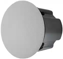
STEP 8
After the speaker is installed, and
transformer tap adjustments are
made, the grille can be installed.
The grille is held in place by
several small, powerful magnets
on the speaker frame. Place the
grille against the speaker and
the magnets will hold it firmly in
place. When properly installed,
the grille should make contact
with the wall all the way around
the speaker (see figure 15).
STEP 6
At this step in the installation the
transformer tap selector can be set.
Depending on your installation you may
wait to set the volume of each speaker
until the system is completely installed
(see figure 13).
STEP 7
Sonance Professional Series loudspeakers
have a pivoting tweeter assembly, allowing
the treble to be directed to the most
suitable location if the speaker is installed
of-axis.
To pivot the drivers apply light pressure
to the ring around the outside edge of
the tweeter cone. Take care not to touch
or apply pressure to the cone itself (see
figure 14).
STEP 5
Tighten the four screws on the front of the
baffle. The Roto-Lock Clamps will rotate
into position automatically and begin
clamping. When you notice resistance
on the four screws, the speaker has been
clamped successfully (see figure 12).
The flange is designed to flex and
conform to any small imperfections in the
ceiling surface.
DROP CEILING INSTALLATION
STEP 1B
The included C-bracket and tile support rails should be used in
all suspended ceiling installations. The C-bracket and tile support
rails can also be used in installations when the speakers are
mounted into material that will not support their weight.
Insert the two tile support rails and C-bracket through the hole
you have cut, placing them as shown. Using the two screws that
are supplied, screw the C-bracket to the tile support rails as
shown (See figure 16).
After the C-bracket and tile support rails are installed follow Step
2 through Step 7 in the standard installation instructions.
INSTALLATION
STEP 4
Make sure the Roto-Lock Clamps are in the full clockwise position
so that all the clamps are tucked within the cutout border. Insert
the speaker into the hole in the ceiling (see figure 11).
NOTE: THE MAXIMUM CLAMP THICKNESS 1.732” (44MM).
TO ACHIEVE MAXIMUM THICKNESS, UNSCREW AND REVERSE
THE FOOT OF THE ROTO-LOCK CLAMPS.
NOTE : FOR DETAILS ON FLEX BRACKET GO TO WWW.SONANCE.COM
SAFETY PRECAUTION
Attaching the seismic tab to a support line is highly
recommended for additional safety.
SAFETY PRECAUTION
Attaching the seismic tab to a support line is highly
recommended for additional safety.
FIGURE 16:
SCREW C-BRACKET
TO TILE SUPPORT RAILS
FIGURE 17:
INSERT SPEAKER
INTO HOLE
FIGURE 15:
GRILLE INSTALLATION
FIGURE 12:
TIGHTEN SCREWS
ON BAFFLE
FIGURE 13:
TRANSFORMER
TAP SELECTION
FIGURE 14:
PIVOT DRIVERS
FIGURE 11:
INSERT SPEAKER
INTO HOLE
Loading ...
Loading ...
Loading ...