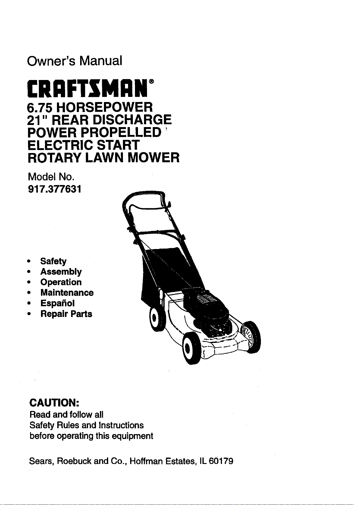
Owner's Manual
(RRFTXMnN°
6.75 HORSEPOWER
21" REAR DISCHARGE
POWER PROPELLED'
ELECTRIC START
ROTARY LAWN MOWER
Model No.
917.377631
• Safety
• Assembly
• Operation
• Maintenance
• Espa_ol
• Repair Parts
CAUTION:
Read and follow all
Safety Rules and Instructions
before operating this equipment
Sears, Roebuck and Co., Hoffman Estates, IL 60179
Warranty 2 Product Specifications 11
Safety:Ru!es 2 Service and Adjustments 14
Assembly 4 Storage 14
Operation 6 Troubleshooting 16
Maintenanc_Scl_edule 10 Repair Parts 34
Main|enance 10 Parts Ordering Back Cover
LIMITEDTWOYEAR WARRANTY ON CRAFTSMAN POWER MOWER
For two years from date of purchase, when this Craftsman Lawn Mower is maintained,
lubricated, and tuned up according to the operating and maintenance instructions in the
owner's manual, Sears will repair free of charge any defect in matedal or workmanship.
If this Craftsman Lawn Mower is used for commercial or rental purposes, this warranty
applies for only 90,days _fromthe date of purchase.
This Warranty does dot cover:
• Expendable items which become worn during normal use such as rotary mower
blades, blade adapters, belts, air cleaners and spark plug.
• Repairs necessary because of operator abuse or negligence, includingbent crank-
shafts and the failure to maintain the equipment according to the instructionscon-
tained in the owner's manual.
Warranty service is available by retuming the Craftsman power mower to the nearest
Sears Service Center/Department in the United States. This warranty applies only while
this product is in use in the United States.
This Warranty gives you specific legal dghts, and you may also have other dghts which
vary from state to state.
SEARS, ROEBUCKAND CO., D/817 WA, HOFFMAN ESTATES, ILLINOIS 60179
TRAINING:
• Read this operator'smanual carefully.
Become familiarwith the controlsand
knowhow to operate your mower
properly. Leam how to quicklystop
mower.
• Do notallow childrento use your mower.
Never allowadultsto use mower without
proper instructions.
• Keep the area of operationclear of all
pemons, especiallysmall children and
pets.
• Use mower onlyas the manufacturer
intended and as descdbed in this manual.
• Do notoperate mower if ithas been
dropped or damaged in any manner.
Always have damage repairedbefore
usingyour mower.
• Do not use accessory attachments that
are not recommended by the manufac-
turer. Use of such attachments may be
hazardous.
• The blade turnswhen the engine is
running.
PREPARATION:
• Always thoroughly check the area to be
mowed and clear it of all stones, sticks,
wires, bones, and other foreign objects.
These objects will be thrown by the blade
and can cause severe injury.
• Always wear safety glasses or eye
shields when starting and while using
your mower,
• Dress properly. Do not operate mower
when barefoot or weadng open sandals.
Wear only solid shoes with good traction
when mowing.
• Checkfueltankbeforestartingengine.
Do not fill gas tank indoors, when the
engine is running or when the engine is
hot. Allow the engine to cool for several
minutes before filling the gas tank. Clean
off any spilled gasoline before stading the
engine.
• Always make wheel height adjustments
before starting your mower. Never
attempt to do this while the engine is
running.
• Mow only in daylight or good artificial
light.
OPERATION:
• Keep your eyes and mind on your mower
and the area being cut. Do not let other
interests distract you.
• Do not mow wet or slippery grass. Never
run while operating your mower. Always
be sure of your footing -- keep a firm
hold on the handles and walk.
• Do not put hands or feet near or under
rotating pads. Keep clear of the discharge
opening at all times.
• Always stop the engine whenever you
leave or are not using your mower, or
before crossing driveways, walks, roads,
and any gravel--covered areas.
• Never direct discharge of material toward
bystanders nor allow anyone near the
mower while you are operating it.
• Before cleaning, inspecting, or repairing
your mower, stop the engine and make
absolutely sure the blade and all moving
pads have stopped. Then disconnect the
spark plug wire and keep it away from the
spark plug to prevent accidental starting.
• DO not continue to run your mower if you
hit a foreign object. Follow the procedure
outlined above, then repair any damage
before restarting and operating you
mower.
• Do not change the govemor settings or
overspeed the engine. Engine damage or
personal injury may result.
• Do not operate your mower if it vibrates
abnormally. Excessive vibration is an
indication of damage; stop the engine,
safely check for the cause of vibration
and repair as required.
• Do not run the engine indoors.Exhaust
fumes are dangerous.
• Never cut grass by pullingthe mower
towardsyou. Mow acrossthe face of
slopes, never up and down or you might
lose your footing. Do not mow exces-
sivelysteep slopes. Use caution when
operatingthe mower on uneven terrain or
when changing directions-- maintain
good footing.
• Never operate your mower withoutproper
guards, plates, grass catcher or other
safety devices in place.
MAINTENANCE AND STORAGE:
• Check the blade and the engine mounting
bolts often to be sure they are tightened
proper .
• Check all belts, nuts and screws at
frequent intervals for proper tightness to
be sure mower is in safe working
condition.
• Keep all safety devices in place and
working.
• To reduce fire hazard, keep the engine
free of grass, leaves or excessive grease
and oil.
• Check grass catcher often for deteriora-
tion and wear and replace wom bags.
Use only replacement bags that are
recommended by and comply with
specifications of the manufacturer of your
mower,
• Always keep a sharp blade on your
mower.
• Allow engine to cool before storing in any
enclosure.
• Never store mower with fuel in the tank
inside a building where fumes may reach
an open flame or an ignition source such
as a hot water heater, space heater,
clothes dryer, etc.
CAUTION: Always disconnect spark plug
wire and place wire where it cannot
contact spark plug in order to prevent
accidental starting when setting up,
transporting, adjusting or making repairs.
WARNING
The engine exhaust from this product
contains chemicals known to the State of
California to cause cancer, birth defects, or
other reproductive harm.
3
Theseaccessoneswereavailablewhen1
availableatmostSearsretailoutletsandservicecenters.MostSearsstorescanalsoorder
repairpartsfor you,whenyouprovidethe modelnumberofyourlawn mower. Some of these
accessories may not apply to your lawn mower.
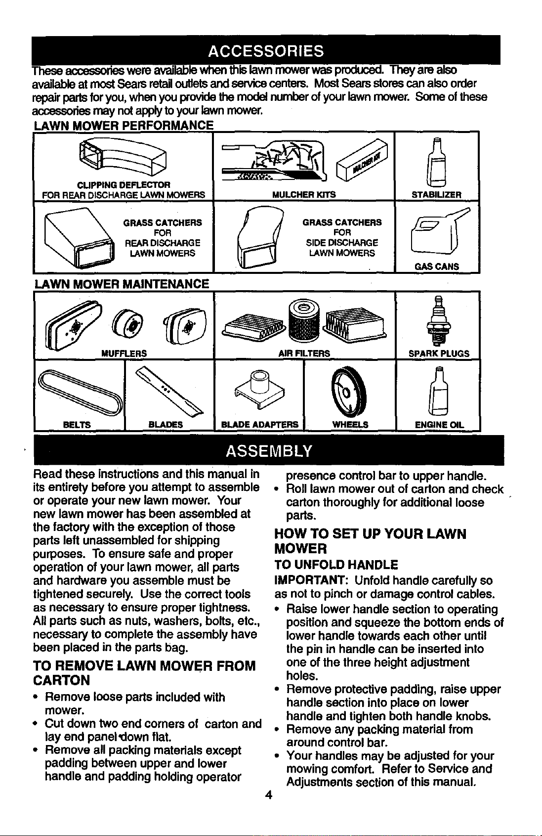
LAWN MOWER PERFORMANCE
CUPPING DEFLECTOR
FOR REAR DISCHARGE LAWN MOWERS
GRASS CATCHERS
FOR
REAR DISCHARGE
LAWN MOWERS
MULCHERKITS
GRASS CATCHERS
FOR
J_ SIDE DISCHARGE
LAWN MOWERS
LAWN MOWER MAINTENANCE
MUFFLERS AIR RLTERS
BELTS BLADES BLADE ADAPTERS WHEELS
STABIUZER
SPARK PLUGS
ENGINE OIL
Read these instructionsand this manual in
its entirety before you attempt to assemble
or operate your new lawn mower. Your
new lawn mower has been assembled at
the factory with the exception of those
parts left unassembled for shipping
purposes. To ensure safe and proper
operation of your lawn mower, all parts
and hardware you assemble must be
tightened securely. Use the correct tools
as necessary to ensure proper tightness.
All parts such as nuts, washers, bolts, etc.,
necessary to complete the assembly have
been placed in the parts bag.
TO REMOVE LAWN MOWER FROM
CARTON
• Remove loose parts included with
mower.
• Cut down two end corners of carton and
lay end panel'down flat.
• Remove all packing materials except
padding between upper and lower
handle and padding holding operator
presence control bar to upper handle.
• Roll lawn mower out of carton and check
carton thoroughly for additional loose
parts.
4
HOW TO SET UP YOUR LAWN
MOWER
TO UNFOLD HANDLE
IMPORTANT: Unfold handle carefully so
as not to pinch or damage control cables.
• Raise lower handle section to operating
position and squeeze the bottom ends of
lower handle towards each other until
the pin in handle can be inserted into
one of the three height adjustment
holes.
• Remove protective padding, raise upper
handle section into place on lower
handle and tighten both handle knobs.
• Remove any packing material from
around control bar.
• Your handles may be adjusted for your
mowing comfort. Refer to Service and
Adjustments section of this manual.
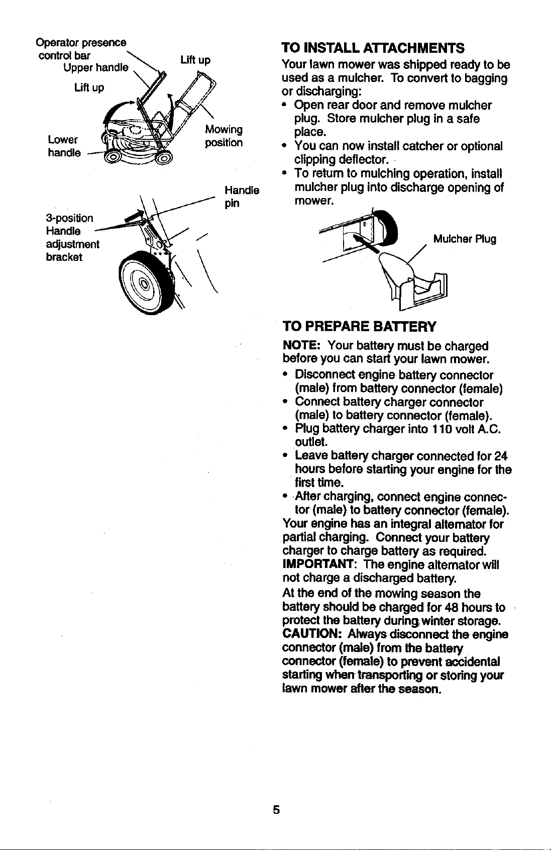
Operator presence
controlbar
Upper handle
Lift up
Lower
handle
3-position
Handle
adjustment
bracket
Lift up
Mowing
position
Handle
pin
TO INSTALL ATrACHMENTS
Your lawn mower was shipped ready to be
used as a mulcher. To convert to bagging
or discharging:
• Open rear door and remove mulcher
plug. Store mulcher plug in a safe
place.
• You can now install catcher or optional
clippingdeflector.
• To return to mulching operation, install
mulcher plug into discharge opening of
mower.
Mulcher Plug
TO PREPARE BATTERY
NOTE: Your battery must be charged
before you can start your lawn mower.
• Disconnect engine battery connector
(male) from battery connector (female)
• Connect battery charger connector
(male) to battery connector (female).
• Plug battery charger into t 10 volt A.C.
outlet.
• Leave battery charger connected for 24
hours before starting your engine for the
first time.
• After charging, connect engine connec-
tor (male) to battery connector (female).
Your engine has an integral altemator for
partial charging. Connect your battery
charger to charge battery as required.
IMPORTANT: The engine altemator will
not charge a discharged battery.
At the end of the mowing season the
battery should be charged for 48 hours to
protect the battery during.winter storage.
CAUTION: Always disconnect the engine
connector (male) from the battery
connector (female) to prevent accidental
startingwhen, transporting or storingyour
lawn mower after the season.
5
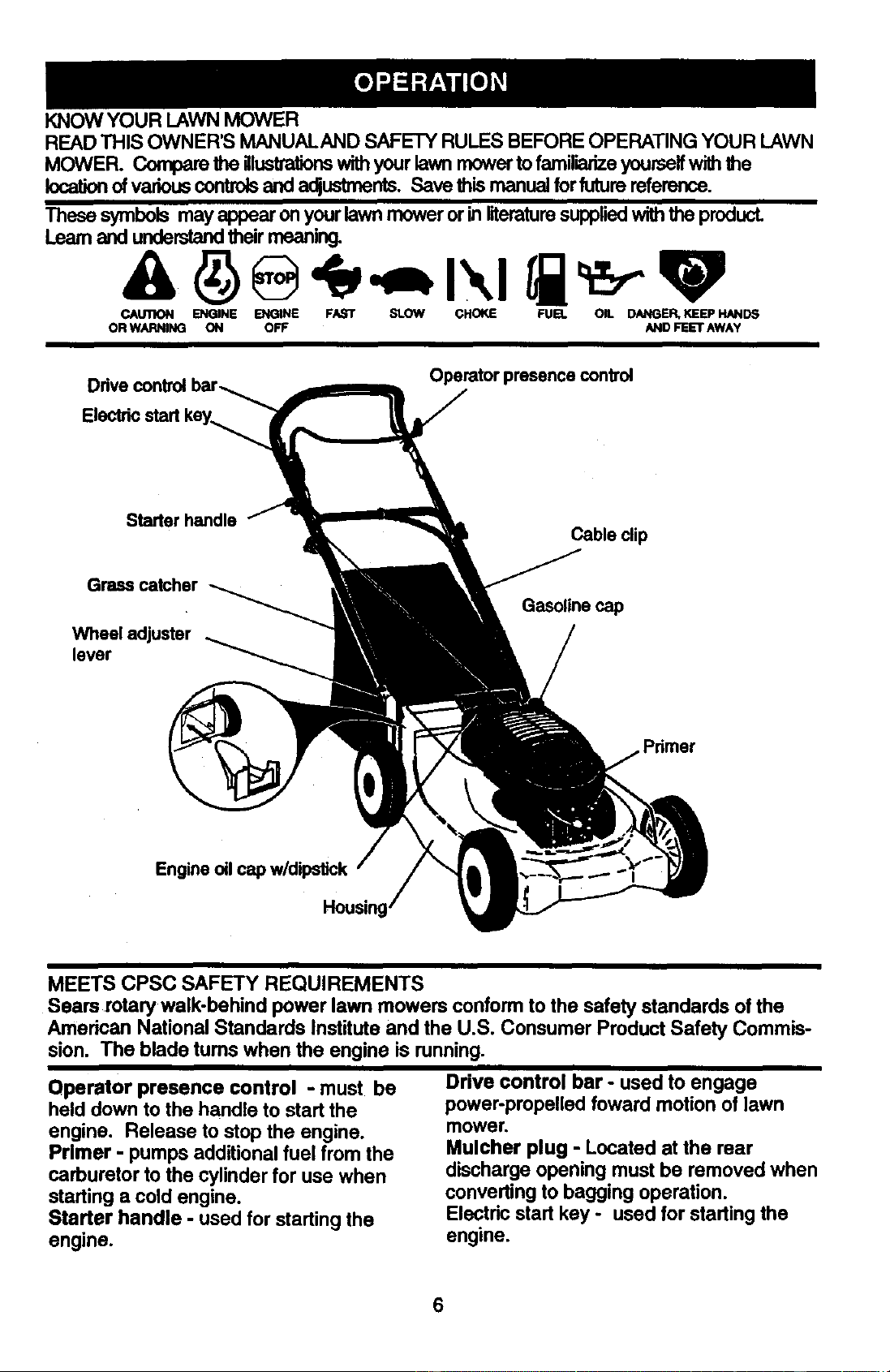
KNOWYOURLAWNMOWER
READ THIS OWNER'S MANUALAND SAFETY RULES BEFORE OPERATING YOUR LAWN
MOWER. Compare the illustrationswith your lawn mower to familiarize yourself with the
location of various controls and a(_uslmer_s. Save this manual for future reference.
These symbols may appearon yourlawnmoweror inliteraturesuppliedwiththe product.
Learnand understandtheirmeaning.
CAUI_)N ENGINE ENGINE FAST SLOW CHOKE FUEL OIL DANGER, KEEP HAND6
OR WARNING ON OFF AND FEET AWAY
Electricstart key_
Operator presence control
Starter handle
Cable clip
Grass catcher
Wheel adjuster
lever
Gasoline cap
Primer
Engine oil cap w/dipstick
MEETS CPSC SAFETY REQUIREMENTS
Sears rotary walk-behind power lawn mowers conform to the safety standards of the
American National Standards Institute and the U.S. Consumer Product Safety Commis-
sion. The blade turns when the engine is running.
Operator presence control - must be
held down to the handle to start the
engine. Release to stop the engine.
Primer - pumps additional fuel from the
carburetor to the cylinder for use when
starting a cold engine.
Starter handle - used for starting the
engine.
Drive control bar - used to engage
power-propelled foward motion of lawn
mower.
Mulcher plug - Located at the rear
discharge opening must be removed when
converting to bagging operation.
Electdc start key - used for starting the
engine.
6
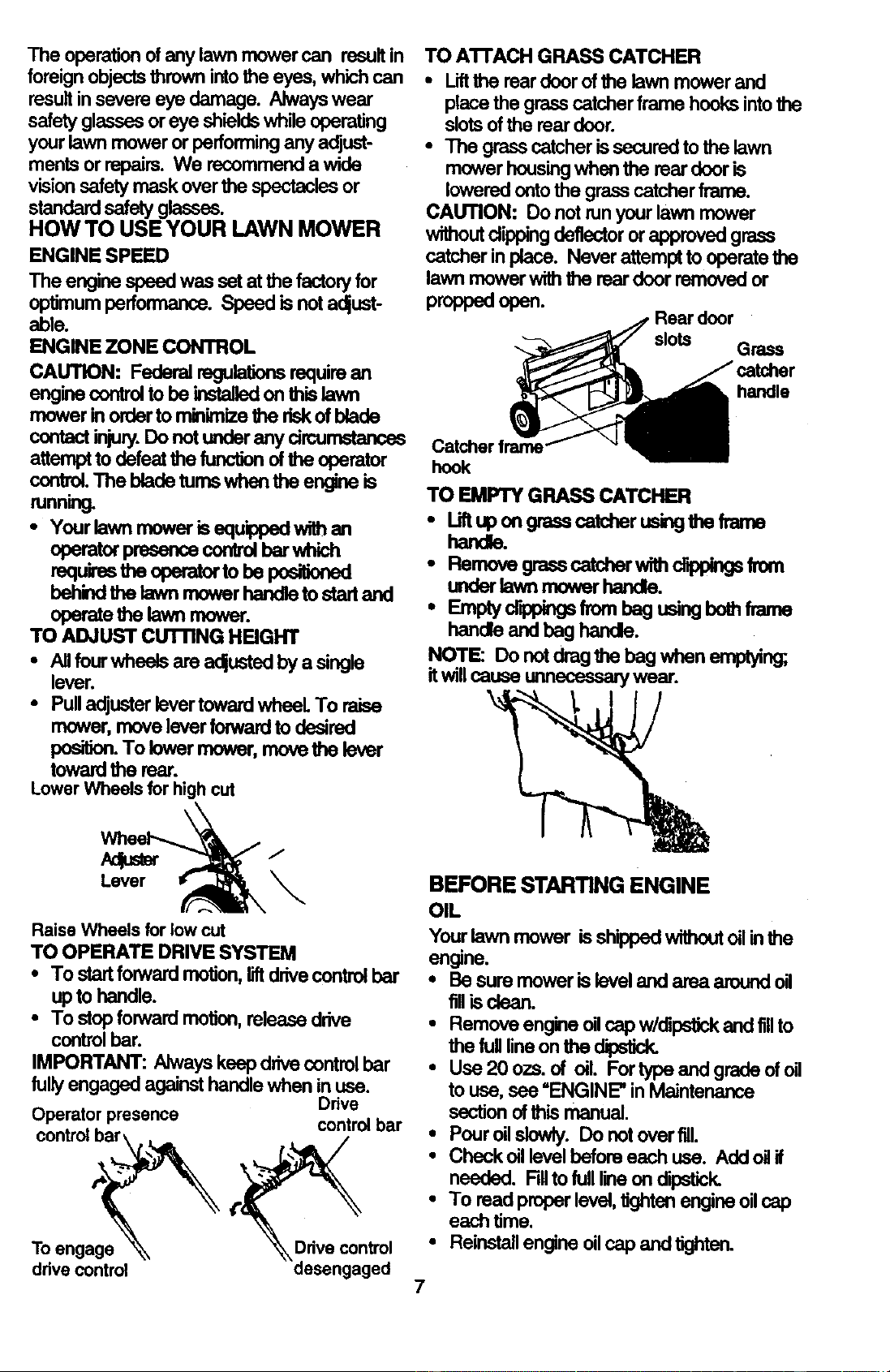
Theoperationofanylawnmowercan resultin
foreign objectsthrownintothe eyes, whichcan
resultinsevereeye damage. Alwayswear
safetyglassesor eye shieldswhile operating
yourlawnmoweror performing any adjust-
mentsorrepairs. We recommenda wide
visionsafetymaskoverthespectaclesor
standardsafetyglasses.
HOW TO USE YOUR LAWN MOWER
ENGINE SPEED
The engine speed was set at the factory for
optimum performance. Speed is not adjust-
able.
ENGINE ZONE CONTROL
CAUTION: Federal regulations require an
engine control to be instalied on this lawn
mower in order to minimize the risk of blade
contact injury.Do not under any drcurnstances
attempt to defeat the function of the operator
control. The blade tums when the engine is
running.
• Your lawn mower is equ'Lopedwith an
operator presenca control bar which
requ','es the operator to be posiSoned
behind the lawn mower handle to start and
operate the lawn mower.
TO ADJUST cUTnNG HEIGHT
• All fourwheels are adjusted by a singie
lever.
• Pull adjustar lever toward wheeL To raise
mower, move lever forward to desired
position. To lower mower, move the lever
toward the rear.
Lower Wheels for high cut
Lever_
Raise Wheels for low cut
TO OPERATE DRIVE SYSTEM
• To start forward motion, liftdrive control bar
up to handle.
• To stop forward motion, release drive
controlbar.
IMPORTANT: Always keep drive control bar
fully engaged against handle when in use.
Drive
Operator presence control bar
control bar\.
To engage_-_ Drivecontrol
drive control desengaged
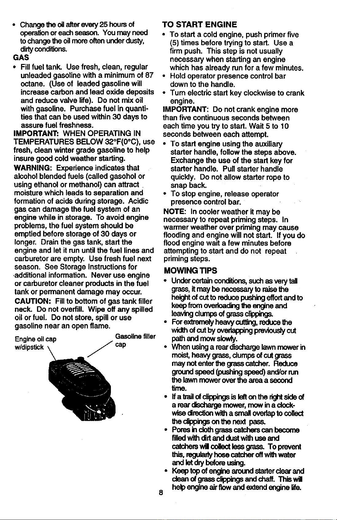
TO A'I'rACH GRASS CATCHER
• Liftthe rear door of the lawn mower and
place the grass catcher frame hooks into the
slots of the rear door.
• The grass catcher is secured to the lawn
mower housing when the rear door is
lowered onto the grass catcher frame.
CAUTION: Do not run your lawn mower
without dipping deflector or approved grass
catcher in place. Never attempt to operate the
lawn mower with the rear door removed or
proppedopen.
_.//7 Rear door
slots Grass
Catcher frame_'_ "_
hook
TO EMPTY GRASS CATCHER
• Lift up on grass catcher using the frame
handle.
• Remevegra_ catcherwi_ cippingsfrom
Lq_,derlawn mowor handle.
• F-mp frombagu ngbothfr ne
handle and bag handle.
NOTE: Do not drag the bag when emptying;
itwill cause unnecessary wear.
BEFORE STARTING ENGINE
OIL
Your lawn mower is shipped without oil in the
an_rle.
• Be sure mower is ievel and area around oil
fillis dean.
• Remove engine oil cap w/dipstick and fillto
the full line on _%edipstick.
• Use20ozs. of oil. For type and grade of oil
to use, see "ENGINE" in Maintenance
section of this manual.
• Pour oil slowly. Do not overfill.
• Check oil level before each use. Add oil if
needed. Fillto full line on dipstick.
• To read proper level, tighten engine oil cap
each time.
• Reinstall engine oil cap and tighten.
7
• Change the oil after every 25 hours of
operation or each season. You may need
to change the oilmore often under dusty,
dirtyconditions.
GAS
• Fill fuel tank. Use fresh, clean, regular
unleaded gasoline with a minimum of 87
octane. (Use of leaded gasoline will
increase carbon and lead oxide deposits
and reduce valve life). Do not mix oil
with gasoline. Purchase fuel in quanti-
ties that can be used within 30 days to
assure fuel freshness.
IMPORTANT: WHEN OPERATING IN
TEMPERATURES BELOW 32°F(0°C), use
fresh, clean winter grade gasoline to help
insure good cold weather starting.
WARNING: Experience indicates that
alcohol blended fuels (called gasohol or
using ethanol or methanol) can attract
moisture which leads to separation and
formation of acids during storage. Acidic
gas can damage the fuel system of an
engine while in storage. To avoid engine
problems, the fuel system should be
emptied before storage of 30 days or
longer. Drain the gas tank, start the
engine and let it run until the fuel lines and
carburetor are empty. Use fresh fuel next
season. See Storage Instructions for
.additional information. Never use engine
or carburetor cleaner products in the fuel
tank or permanent damage may occur.
CAUTION: Fill to bottom of gas tank filler
neck. Do not overfill. Wipe off any spilled
oil or fuel. Do not store, spill or use
gasoline near an open flame.
Gasoline filler
Engine oil cap
w/dipstick J cap
TO START ENGINE
• To start a cold engine, push primer five
(5) times before trying to start. Use a
firm push. This step is not usually
necessary when starting an engine
which has already run for a few minutes.
• Hold operator presence control bar
down to the handle.
• Turn electric start key clockwise to crank
engine.
IMPORTANT: Do not crank engine more
than five continuous seconds between
each time you try to start. Wait 5 to 10
seconds between each attempt.
• To start engine using the auxiliary
starter handle, follow the steps above.
Exchange the use of the start key for
starter handle. Pull starter handle
quickly. Do not allow starter rope to
snap back.
• To stop engine, release operator
presence control bar.
NOTE: In cooler weather it may be
necessary to repeat priming steps. In
warmer weather over priming may cause
flooding and engine will not start. If you do
flood engine wait a few minutes before
attempting to start and do not repeat
priming steps.
MOWING TIPS
• Undercertainconditions, suchas verytall
grass,it maybe necessaryto raissthe
heightofcuttoreducepushingeffortand to
keep fromoverloading_ engineand
leavingdumps ofgrassclippings.
• Forextremelyheavycutting,reducethe
widthofcutby overlappingpreviouslycut
pathand mowslowly.
• When usinga rearolschargelawn mowerin
moist,heavygrass,dumps ofcut grass
may notentarthe grasscatcher. Reduce
groundspeed (pushingspeed)and/orrun
the lawn mower over the area a second
time.
• Ifa trailofclippingsis lefton the dghtside of
a rear arBchargemower,mow ina clock-
wisedirectionwitha smallovedaptocollect
theclippingson the next pass.
• Poresinclothgrasscatcharscan become
filledwithdirtand dustwithuse and
catcherswil collectlessgrass. Toprevent
this,regularlyhoeacatcheroffwithwatar
and letdrybeforeusing.
• Keeptop of enginearoundstarterclear and
dean ofgrasecrtppingsand cheff. Thiswill
8 helpengineair flowand extendenginelife.

MULCHINGMOWINGTIPS
IMPORTANT: For best performance, keep
mower housing free of built-up grass and
trash. See =Cleaning" in Maintenance section
of this manual.
• The spec'BImulchingblade willrecutthe
grassclippingsmany timesand reduce
them insize sothat as theyfall ontothe
lawnthey will disperseintothe grassend
notbe noticed. ALso,the mulchedgrasswill
biodegradequicklyto providenutrientsfor
the lawn. Alwaysmulchwithyourhighest
engine (blade)speed as thiswillprovidethe
bestrecurringactionof the blades.
• AvokJcuttJngyourlawnwhen itiswet. Wet
grasstendstoformdumps and interferes
withthe mulchingaction. The besttimeto
mowyourlawn is the eady afternoon.At
this time the grasshas driedand the newly
cutarea will notbe exposedto the direct
sun.
• For bestresults,adjustthe lawn mower
cuttinghekjhtso thatthe lawnmowercuts
offonlythe topone-thirdofthe grassblades.
Ifthe lawn is overgrownitw,I be necessary
to raisethe heightofcutto reducepushing
effortand to keepfromoverloadingthe
engineand leavingdumps ofmulched
grass.For extremelyheavy mulching,
reduceyourwidthof cutbyoverlapping
previouslycutpathand mowslowly.
• Certaintypesofgrassandgrasscenditions
mayrequirethatan area be mulcheda
secondtime to completelyhidethe
clippings.When doinga secondcut,mow
acrossorperpendiculartothe firstcutpath.
• ChangeyourcutlJngpatternfromweek to
week. Mow northtosouthone weekthen
changetoeasttowestthe next wask. This
willhelppreventmattingand grainingofthe
lawn.
9
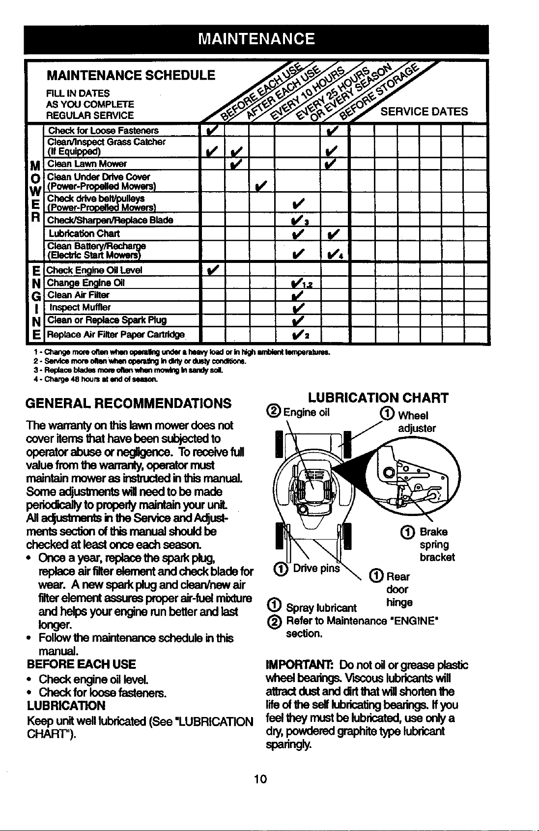
.A,NTENANCESCHEDULE
O_ _ 0 _ 0_
AS YOU COMPLETE ______- _ _ _ _€'x_- _
ir _l,_ -jr -
CheckforLoose Fasteners I,/ ; ll/
Clean4nspectGrassCatcher
_ Clean Lawn Mower
Clean Under_tve Cover
W (Power-Propelled Mowers) I/Checkdr_e beN/pulk_/s ._
(Power-Pmpe.ed Mowers)
R chac_s_c8 S_de s
LubricationChart I/
Clean Battep//Rechar!_le
IElectric Start Mowers/ I/ I/4
NEChackEng_ O,L_,_ it/
Change Engine Oil 1_1.2
G
Clean Air Filter
Clean or Replace Spark Plug
E ReplaceAirRlterPaperCartridge _=
1 -Q_nge rnom_l_n wl_ q_iling .ndl_ a helvy loadmIn highIlmbl_t le_ermms.
2 - Sen4cemornonenwheno1_ btdhtyor_sly €ondlUo_.
3 - Replaceb_dm moruoltenwhenmowingInsardysol.
4 - Charge48 houmat endofseuoJ_
GENERAL RECOMMENDATIONS
The warranty on this lawn mower doas not
cover items that have been subjected to I --
operator abuse or negligence. To receive full II
value from the wananty, operator must / "----
maintain mowerasinstructedinthismanual. //
Some adjustments will need to be made |'H
periodically to properly maintain your unit.
All_ inlheSen4ceaedAdjust-
mentssection of this manual should be I
checked at least once each season. _--_
• Onceayear,replacethespsrkp_,
replaceairlilterelementandcheckbladefor (_
wear. A newsparkplugandclean/newair
filterelement assures proper elr-fuel mixture
andhelpsyourenginerunbetterandlast
longer.
• Follow the maintenance schedule in this
manual.
BEFORE EACH USE
• Check engine oil level.
• Check for loose fasteners.
LUBRICATION
Keep unit well lubricated (See "LUBRICATION
CHART").
LUBRICATION CHART
(_) Engine oil _Wheel
adjuster
(_ Brake
spring
bracket
(_) Rear
door
hinge
(_ Spray lubricant
(_ Refer to Maintenance "ENGINE"
section.
IMPORTANT: Do not oil or grease plastic
wheel bearings. VL_couslubricants will
attract dust and dirt that WIllshoden the
lifeof the serf lubricating bearings, ffyou
feel they must be lubricated, use only a
dry,powdered graphite type lubricant
sp_ng_.
10
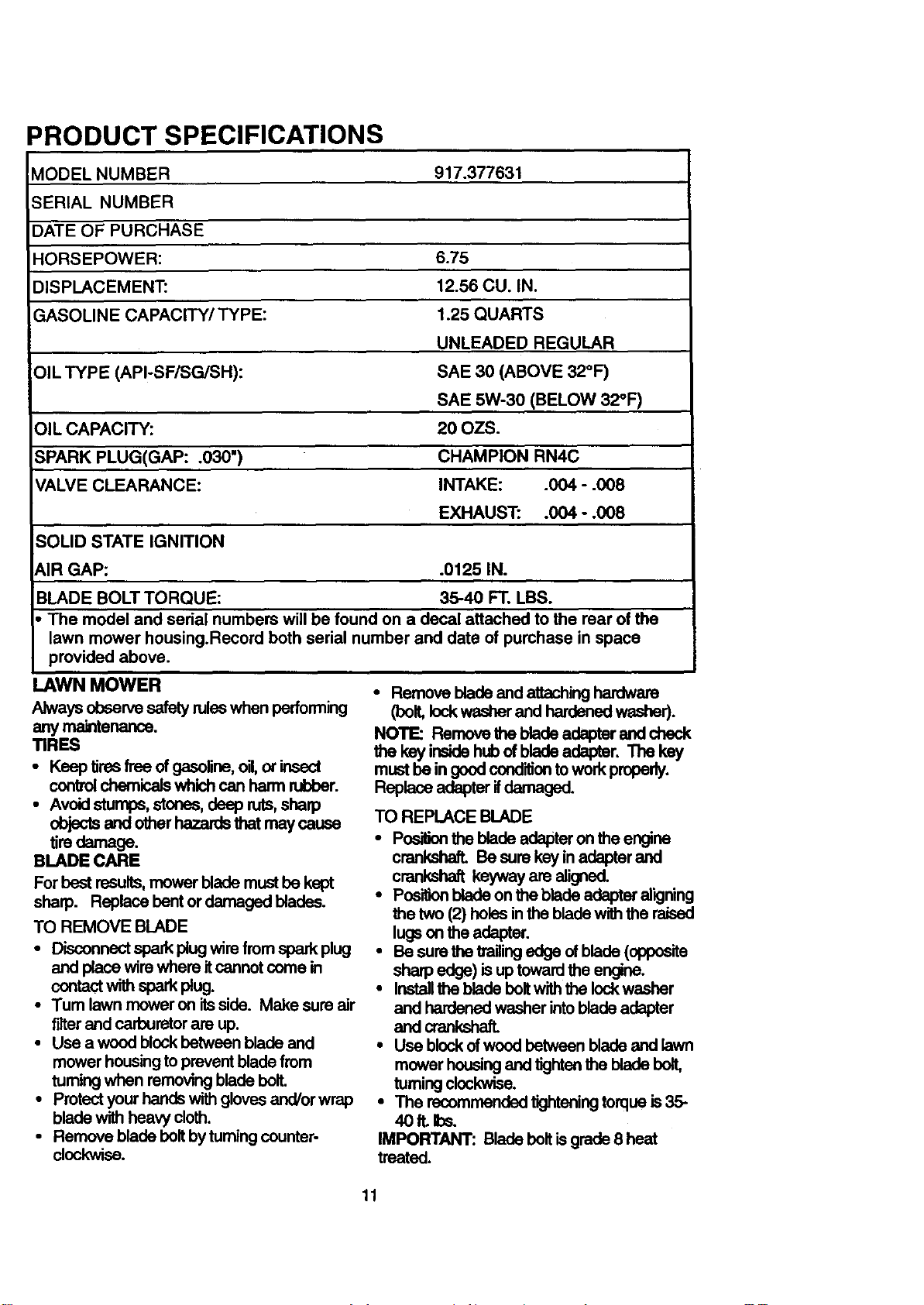
PRODUCT SPECIFICATIONS
MODEL NUMBER 917.377631
SERIAL NUMBER
DATE OF PURCHASE
HORSEPOWER: 6.75
DISPLACEMENT: 12.56 CU. IN.
GASOLINE CAPACITY/TYPE: 1.25 QUARTS
UNLEADED REGULAR
OIL TYPE (API-SF/SG/SH): SAE 30 (ABOVE 32°F)
SAE 5W-30 (BELOW 32°F)
OIL CAPACITY: 20 OZS.
SPARK PLUG(GAP: °030") CHAMPION RN4C
VALVE CLEARANCE: INTAKE: .004 - .008
EXHAUST: .004 - .008
SOLID STATE IGNITION
AIR GAP: .0125 IN.
BLADE BOLT TORQUE: 35-40 FT. LBS.
• The model and serial numbers will be found on a decal attached to the rear of the
lawn mower housing.Record both serial number and date of purchase in space
provided above.
LAWN MOWER
Alwaysobservesafetyruleswhen performing
any maintenance.
TIRES
• Keep tiresfree ofgasoline,oil,or insect
controlchemicalswhichcan harmrubber.
• Avoid stumps,stores, deepruts,sharp
objectsand otherhazardsthat maycause
tiredamage.
BLADE CARE
For bestresults,mowerblade mustbe kept
sharp. Replacebentor damagedblades.
TO REMOVE BLADE
• Disconnect sparkplugwirefromsparkplug
and placewirewhere itcannotcome in
contactwithsparkplug.
•Tum lawn moweron itsside. Make sureair
filterand carburetor are up.
• Use a woodblockbetween bladeand
mower housingto preventbladefrom
tumingwhen removingblade bolt.
• Protectyourhandswithglovesand/orwrap
bladewithheavycloth.
• Remove blade bolt byturningcounter-
clockwise.
• Removebladeand attachinghardware
(boll lockwasherand hardenedwasher).
NOTE: Removethe blade adapterand check
the key insidehubof blade adapter. The key
mustbe in goodcondifiontoworkproperly.
Replaceadapterifdamaged.
TO REPLACE BLADE
• Posifionthe bladeadapteronthe engine
cranksha_ Besure keyinadapterand
crankshaftkeywayare aligned.
• Pos'Cdonblade on theblade adapteraligning
the two (2) holesinthe bladewiththe raised
lugson the adapter.
• Be surethetrailingedge ofblade (opposite
sharpedge)isuptowardthe engine.
• Installthe bladeboltwiththelockwasher
and hardenedwasherintobladeadapter
and crankshaft.
• Use blockof woodbetweenbladeand lawn
mowerhousingandtightenthe bladebolt,
tumingclockwise.
• The recommendedtighteningtorqueis 35-
40 It. bs.
IMPORTANT: Bladebolt is grade8 heat
treated.
11
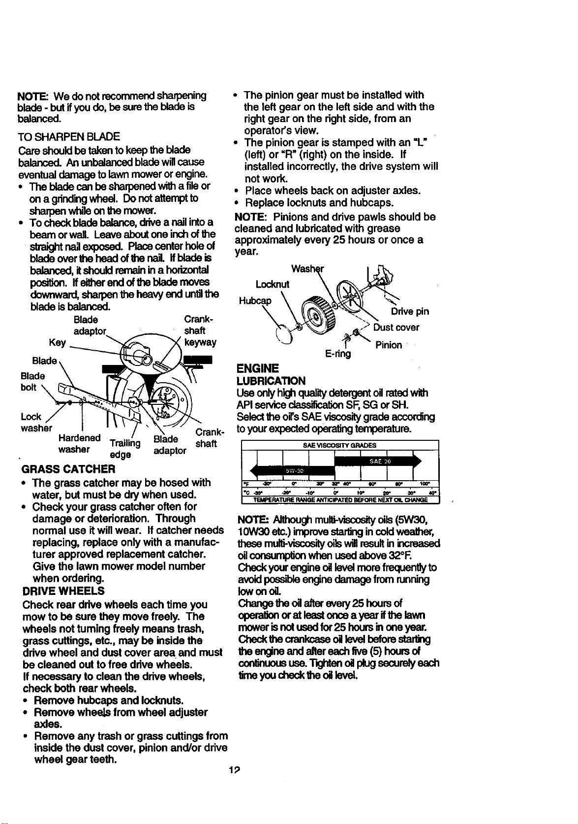
NOTE'. We do not recommend sharpening
blade - but if you do, be sure the blade is
balanced.
TO SHARPEN BLADE
Care should be taken to keep the blade
balanced. An unbalanced blade will cause
eventual damage to lawn mower or engine.
• The blade can be sharpened with a file or
ona gdndingwheel.Donotattemptto
shaq_mwhilaonthernower.
• To check blade balance, drive a nsil into a
beam or wall. Leave about one inch of the
straight r_l exposed. Place center hole of
blade over the head of 81e nail. If blade is
balanced, it should remain in a horizontal
pes_. Iferd_ e_ of_e blede m_se
downward, shaq0en the heavy end untilthe
blade is balanced.
Blade Crank-
shaft
keyway
Blade
bolt
Lock
washer Crank-
Hardened Trailing Blade shaft
washer edge adaptor
GRASS CATCHER
• The grass catcher may be hosed with
water, but must be dry when used.
• Check your grass catcher often for
damage or deterioration. Through
normal use it will wear. If catcher needs
replacing, replace only with a manufac-
turer approved replacement catcher.
Give the lawn mower model number
when ordedng.
DRIVE WHEELS
Check rear drive wheels each time you
mow to be sure they move freely. The
wheels not tuming freely means trash,
grass cuttings, etc., may be inside the
ddve wheel and dust cover area and must
be cleaned out to free ddve wheels.
If necessary to clean the drive wheels,
check beth rear wheels.
• Remove hubcaps and Iocknuts.
• Remove wheels from wheel adjuster
axles.
• Remove any trash or grass cuttings from
inside the dust cover, pinion and/or drive
wheel gear teeth.
19
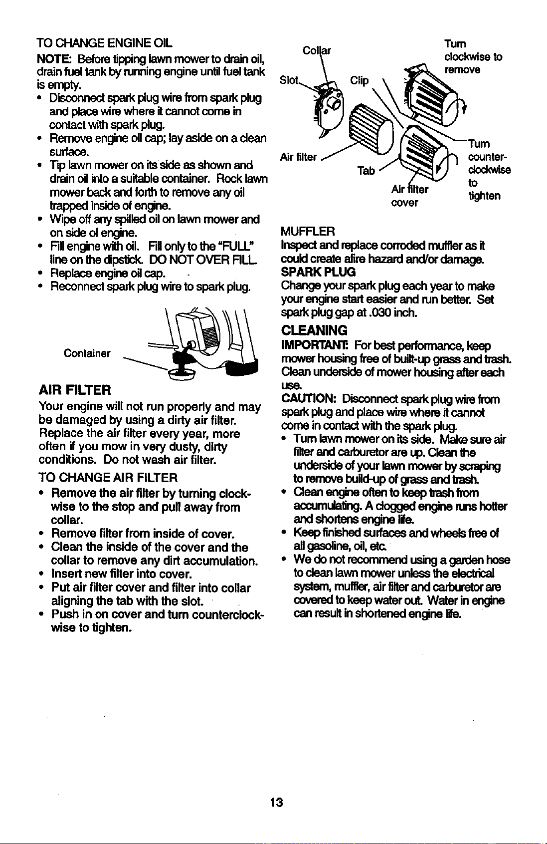
• The pinion gear must be installed with
the left gear on the left side and with the
right gear on the right side, from an
operator's view.
• The pinion gear is stamped with an "L"
(left) or =R" (right) on the inside. If
installed incorrectly, the drive system will
not work.
• Place wheels back on adjuster axles.
• Replace Iocknuts and hubcaps.
NOTE: Pinions and drive pawls should be
cleaned and lubricated with grease
approximately every 25 hours or once a
year.
Locknut
Ddve pin
Dust cover
Pinion
E-dng
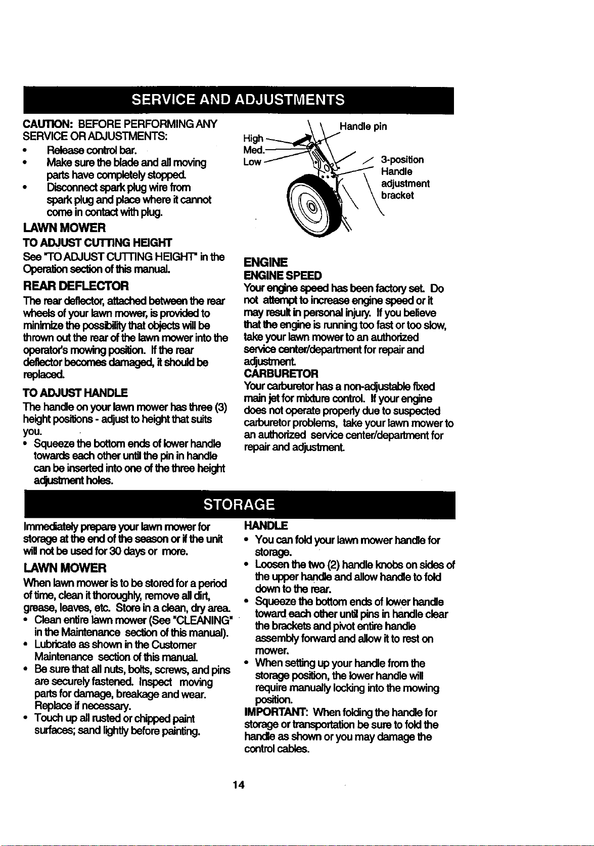
ENGINE
LUBRICATION
Use only high quality detergent oil rated wi_
API service classification SF, SG or SH.
Select the oil's SAE viscosity grade according
to your expected operating temperature.
NOTE: _ mull_viscosityoils (5W30,
10W30 etc.)improvestartingincoldweather,
thesemulti-viscos'_oilswillresultinincreased
oilconsumpt_ when used above32°1-.
Checkyourengineoillevelmorefrequentlyto
avoidposs_leenginedamagefrom running
lowon oil.
Cringe the oq_er every25 houmof
operationorat leastonce a year ifthe lawn
rnowerisnotusedfor25 hoursin one year.
Checkthe crankcaseoil lavel beforesta_ng
the engineand aftereachEve(5) hoursof
conlinuoususe.T_hton oUplugsecurelyasch
timeyoucheckthe oil lavel.
TOCHANGEENGINE OIL
NOTE: Beforetippinglawn mowertodrainoil,
drainfueltankby runningengineuntilfuel tank
isempty.
• Disconnectsparkplugwirefrom sparkplug
and place wirewhereit cannotcomein
contactwithsparkplug.
• Removeengineoilcap;layasideon a clean
Surface.
• Tip lawn moweron itssideas shownand
drainoilinto a suitablecontainer.Rock lawn
mower backand forth to removeany oil
trappedinsideof engine.
• Wipe offanyspilled oilon lawn mowerand
on sideof engine.
• RUenginewithoil RUonlyto the =FULL"
lineon the _ DO NOT OVER RLL
• ReplaceengineoHcap. .
Reconnectsparkplugwiretosparkplug.
Container
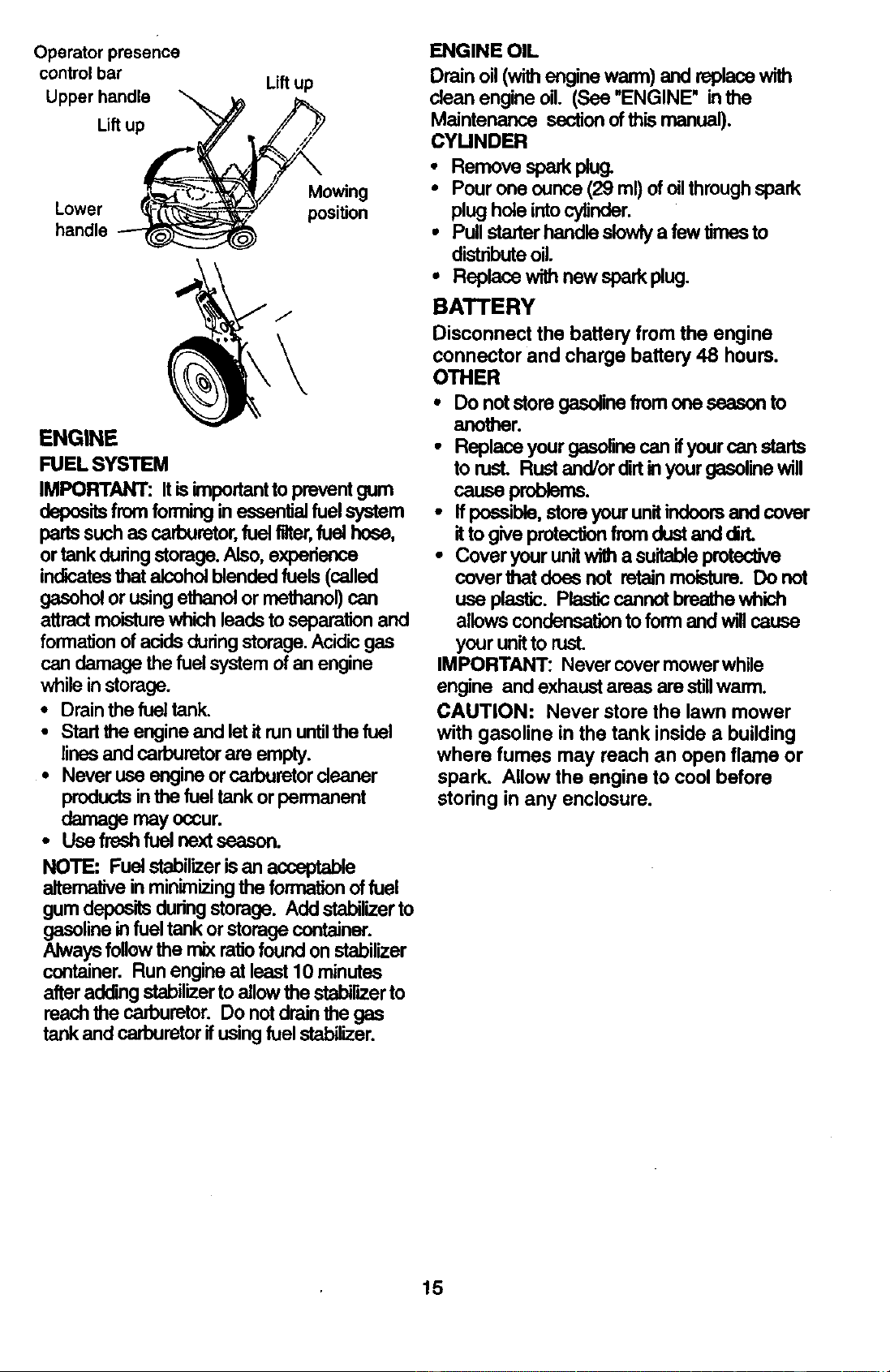
AIR FILTER
Your engine will not runproperly and may
be damaged by using a dirty air filter.
Replace the air filter every year, more
often if you mow in very dusty, dirty
conditions. Do notwash air filter.
TO CHANGE AIR FILTER
• Remove the air filter by tuming clock-
wise to the stop and pull away from
collar.
• Remove filter from inside of cover.
• Clean the inside of the cover and the
collar to remove any dirt accumulation.
• Insert new filter into cover.
• Put air filter cover and filter into collar
aligning the tab with the slot.
• Push in on cover and turn counterclcck-
wise to tighten.
slot_
Clip
Tum
clockwiseto
remove
counter-
clockwise
Airt to
tighten
cover
MUFFLER
Inepectand replaceccrroded muffleras it
couldcreateafirehazardand/ordamage.
SPARK PLUG
Changeyoursparkplugeachyear to make
yourenginestarteasierand runbetter. Set
sparkpluggap at .030 inch.
CLEANING
IMPORTAN'E Forbestperformance,keep
rnowerhousingfree ofbuiit-upgrassandtresh.
Clean undersideofmower housingaftereach
use.
CAUTION: Disconnectsparkplug wire from
sparkplug and placewire where it cannot
comeincontact withthe sparkplug.
• Tum lawnmoweron itsside. Make sureair
filterandcadouretorare up.Clean the
undersideofyourlawn mower byscraping
toremovebuild-upofgrassandtrash.
• Clean engineoftentokeeprash from
accumulating.A dogged engine runshotter
andsbe_ne engine lile.
• Keep finishedsurfacesandwheelsfreeof
allgasoline,=1,at=
• We do notreccmmendusinga gardenhose
tocleanlawn mowerunlessthe electrical
system,muffler,airfilterand carburetorare
coveredtokeepwater out. Water inengine
can resultinshortenedengine life.
13
CAUTION: BEFORE PERFORMING ANY
SERVICE OR ADJUSTMENTS:
• Ralease control bar.
• Make sure the blade and all moving
parts have completely stopped.
• Disconnsoteparkplugwirefrom
spark plug and place where itcannot
come in contact with plug.
LAWN MOWER
TO ADJUST CuI"nNG HI=IGHT
See "-ro ADJUST CU'I-RNG HEIGHT" in the
Operatio_ section of this manual
REAR DEFLECTOR
The rear deflector, attached betwean the rear
wheels of your lawn mower, is provided to
minimize the possibilitythat objects will be
thrown out the reer of the lawn rnower into the
operators mowing posltlen. If the rear
deflector becomas damaged, it should he
repiaced.
TO ADJUST HANDLE
The handle on your lawn mower has three (3)
height positions - adjust to height that suits
you.
• Squeeze the bottom ends of tower handie
towards each other untilthe pin in handle
can be inserted into one of the three height
adjustmentholes.
ied.-
Low
Handle pin
/ 3-position
Handle
adjustment
bracket
ENGINE
ENGINE SPEED
Yourangine speed has been factory set. Do
not attempttoincreaseengineepeadorit
may result in personal injury. If you believe
that _ engine is running too fast ortoo slow,
take your lawn mower to an authorized
service center/departmant for repair and
adjustment.
CARBURETOR
Your carburetor has a non-adjustable fixed
main jet for mixture control, ffyour engine
deasnotuperateproperlyduetosuepected
carburetor problems, take your lawn mower to
an authorized se_ce center/department for
repair and adjustment.
Im_aly prepareyourlawnmowerfor
storageatthe end of the seasoner ifthe unit
willnothe usedfor30 daysor more.
LAWN MOWER
When lawnmower isto be stored fora period
of time, cleanitthoroughly, removeall dirt,
grease,leaves,etc. Storeina clean,dryarea.
• Clean entirelawnmower(See "CLEANING"
inthe Maintenance sectionof this manual).
• Lub_ate as showninthe Customer
Maintenance sectionof_ls manual.
• Besurethat allnuts,bolts,screws,and pins
are securelyfastened. Inspect moving
partsfordamage, breakageand wear.
Replaceifnecessap/.
• Touchup all rustedorchippedpaint
surfaces;sand lightlybeforepainting.
HANDLE
• You can fold your lawn mower handle for
storage.
• Loosen the two (2) handle knobs on sides of
the upper handle and allow handle to fold
down to the rear.
• Squeeze the bottom ends of lower hendle
toward each other untilpins in handle clear
the brackets and pivot entire handle
assembly forward and allow it to reston
mower.
• When setting up your handle from the
storage position, the lower handle will
require manually locking into the mowing
position.
IMPORTANT: When folding the handle for
storage or transportation be sure to fold the
handle as shown or you may damage the
controlcables.
14
Operatorpresence
controlbar
Upperhandle
Lift up
Lift up
Lower
handle
Mowing
position
ENGINE
FUEL SYSTEM
IMPORTANT: It is important to prevent gum
deposits from forming in essential fuel system
parts such as carburetor, fuel filter, fuel hose,
or tank during storage. Also, experience
indicates that alcohol blended fuels (called
ge_hoi or using ethanol or methanol) can
attract moisture which leads to separation and
formation of acids during storage. Acidic gas
can damage the fuel system of an engine
while in storage.
• Drain the fuel tank.
• Start the engine and let it run untilthe fuel
lines and carburetor are empty.
• Never use engine or carburetor cleaner
products inthe fuel tank or permanent
damage may occur.
• Use fresh fuel next sasson.
NOTE: Fuel stabilizer is an acceptable
altemative in minimizing the formation of fuel
gum deposits during storage. Add stabilizer to
gasoline in fuel tank or storage container.
Always follow the mix ratio found on stabilizer
container. Run engine at least 10 minutes
after ad_ng stabilizer to allow the stabilizer to
reach the carburetor. Do not drain the gas
tank and carburetor if using fuel stabilizer.
ENGINE OIL
Drain oil (with engine warm) and replace with
clean engine oil. (See "ENGINE" inthe
Maintenance section of this manual).
CYLINDER
• Remove spa_ plug.
• Pourone ounce(29 ml)ofoilthroughspark
plug holeintocylinder.
• Pullstaderhandleslowlya fewtimesto
distributeoil.
• Replace withnew sparkplug.
BATTERY
Disconnect the battery from the engine
connector and charge battery 48 hours.
OTHER
• Do notstoregaselinefromone seasonto
another.
• Replaceyourgasolinecanifyourcan starts
to rust. Rustand/or dirtin yourgasolinewill
causeproblems.
• ffpossible,stere yourunitindoorsand cover
itto giveprotectionfrom dustand dirt.
° Cover yourunitwitha suitableprotective
coverthat does not retainmoisture. Donot
use plastic. Plasticcannotbreathewhich
allowscondensationto form and will cause
yourunitto rust.
IMPORTANT: Nevercovermowerwhile
engine and exhaustareas are stillwarm.
CAUTION: Never store the lawn mower
with gasoline in the tank inside a building
where fumes may reach an open flame or
spark. Allow the engine to cool before
storing in any enclosure.
15
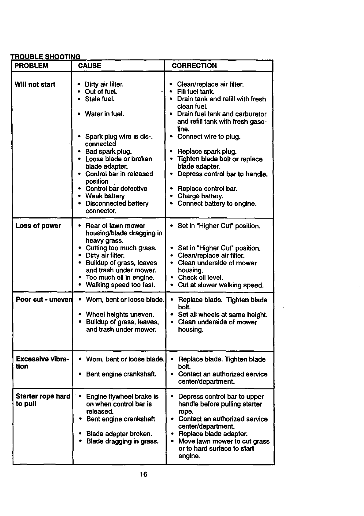
TROUBLESHOOTING
PROBLEM CAUSE CORRECTION
Will not start
Loss of power
Poor cut - unever
Excessive vibra-
tion
Starter rope hard
to pull
• Dirty air filter.
• Out of fuel.
• Stale fuel.
• Water in fuel.
• Spark plug wire is dis-.
connected
• Bad spark plug.
• Loose blade or broken
blade adapter.
• Control bar in released
position
• Control bar defective
• Weak battery
• Disconnected battery
connector.
• Rear of lawn mower
housing/blade dragging in
heavy grass.
• Cutting too much grass.
• Dirty air filter.
• Buildup of grass, leaves
and trash under mower.
• Too much oil in engine.
• Walking speed too fast.
•Wom, bent or loose blade.
• Wheel heights uneven.
• Buildup of grass, leaves,
and trash under mower.
•Wom, bent or loose blade.
• Bent engine crankshaft.
• Engine flywheel brake is
on when control bar is
released.
• Bent engine crankshaft
• Blade adapter broken.
• Blade dragging in grass.
• Clean/replace air filter.
• Fill fuel tank.
• Drain tank and refill with fresh
clean fuel.
• Drain fuel tank and carburetor
and refill tank with fresh gaso-
line.
• Connect wire to plug.
• Replace spark plug.
• Tighten blade bolt or replace
blade adapter.
• Depress control bar to handle.
• Replace control bar.
• Charge battery.
• Connect battery to engine.
• Set in "Higher Cut"position.
• Set in "Higher Cut" position.
• Clean/replace air filter.
• Clean underside of mower
housing.
, Check oil level.
• Cut at slower walking speed.
• Replace blade. Tighten blade
bolt.
• Set all wheels at same height.
• Clean underside of mower
housing.
• Replace blade. "l]ghten blade
bolt.
• Contact an authorized service
center/department.
• Depress control bar to upper
handle before pulling starter
rope.
• Contact an authorized service
center/department.
• Replace blade adapter.
• Move lawn mower to cut grass
or to hard surface to start
engine.
16

TROUBLESHOOTING
)ROBLEM CAUSE CORRECTION
Loss of drive • Drivewheelsnotturning • Adjustor replacedrivecontrol
(Self-Propelled withdrivecontrolengaged, cable,if broken.
Mowing) • Belt notdriving. • Put belton pulleysor replace
beltsif broken.
Grass catcher • Cuttingheighttoolow. • Raisecuttingheight.
not filling (If so • Liftonbladewomoff. !• Replace blade.
equipped) • Catcher not venting air. _ • Clean grass catcher.
• Raise cutting height.
Hard to push • Grass is too high or wheel
height is too low.
Rear of lawn mower
housing/blade dragging
in grass.
Grass catcher too full.
Handle height position not
dght for you.
• Raise rear of lawn mower
housing one (1)
setting higher.
• Empty grass catcher.
• Adjust handle height to suit.
17
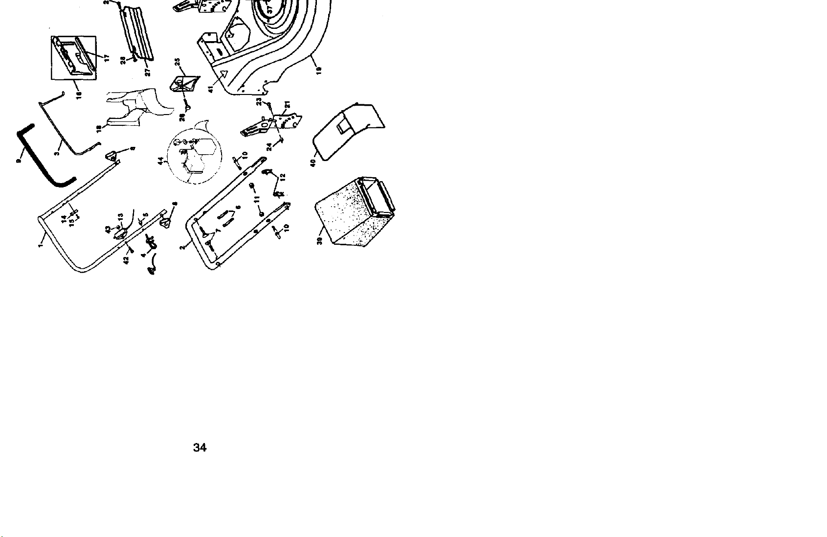
ROTARY LAWN MOWER - - MODEL NO. 917.377631
co
.b.
42,
4
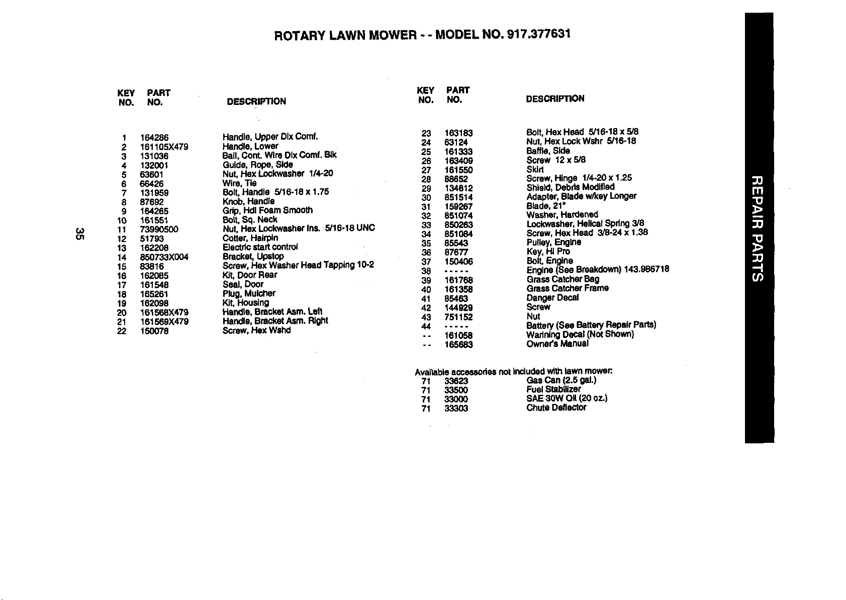
ROTARY LAWN MOWER - - MODEL NO. 917.377631
KEY PART
NO. NO.
DESCRIPTION
KEY PART
NO. NO. DESCRIPTION
(,o
O1
1 164286
2 161105X479
3 131036
4 132001
5 63601
6 66426
7 131959
8 87692
9 164265
10 16"t551
11 73990500
12 51793
13 162208
14 850733X004
15 83816
16 162085
17 161548
18 165261
19 162098
20 161568X479
21 161569X479
22 150078
Handle, Upper DIx Comf.
Handle, Lower
Bail, Cont. Wire OIxComf. BIk
Guide, Rope, Side
Nut, Hex Lookwasher 114-20
Wire, Tie
Bolt,Handle 5/16-18 x 1.75
Knob, Handle
Grip, Hdl Foam Smooth
Bolt,Sq. Neck
Nut, Hox Look'washerIns. 5/16-18 UNC
Cotter, Hairpin
Electricstart cootrol
Bracket, Upstop
Screw, Hex Washer Head Tapping 10-2
Kit, Door Rear
Seal, Door
Plug, Mulcher
Kit, Housing
Handle, Bracket Asm. Left
Handle, Bracket Asrn. Right
Screw, Hex Wahd
23 163183 Bait, He)( Head 5/16-18 x 5/8
24 63124 Nut, Hex LockWshr 5/16-18
25 161333 Baffle, Side
26 163409 Screw 12 x 5/8
27 161550 Skirt
28 88652 Screw, Hinge 1/4-20 x 1.25
29 134612 Shield, Deb#.sMoo]fled
30 851514 Adapter, Blade w/key Longer
31 158267 Blade, 21"
32 851074 Washer, Hardened
33 850263 Lookwasher,HelicalSpdng 3/8
34 851084 Screw, Has Head 3/8-24 x 1.38
35 85543 Pulley, Engine
36 87677 Key,HI Pro
37 150406 Bolt,Engine
38 ..... Engine (See Breakdown) 143.986718
39 181768 GrassCatcher Bag
40 161358 Grass Catcher Frame
41 85463 Danger Decal
42 144929 Screw
43 751152 Nut
44 ..... Battery (Sea Battery Repair Parts)
- - 161058 Warlning Decal (Not Shown)
- - 165683 Owner's Manual
Availableaccessories not includedwith lawn mower:.
71 33623 Gas Can (2.5 gal.)
71 33500 Fuel Stabilizer
71 33000 SAE 30W Og (20 oz.)
71 33303 Chute Deflector
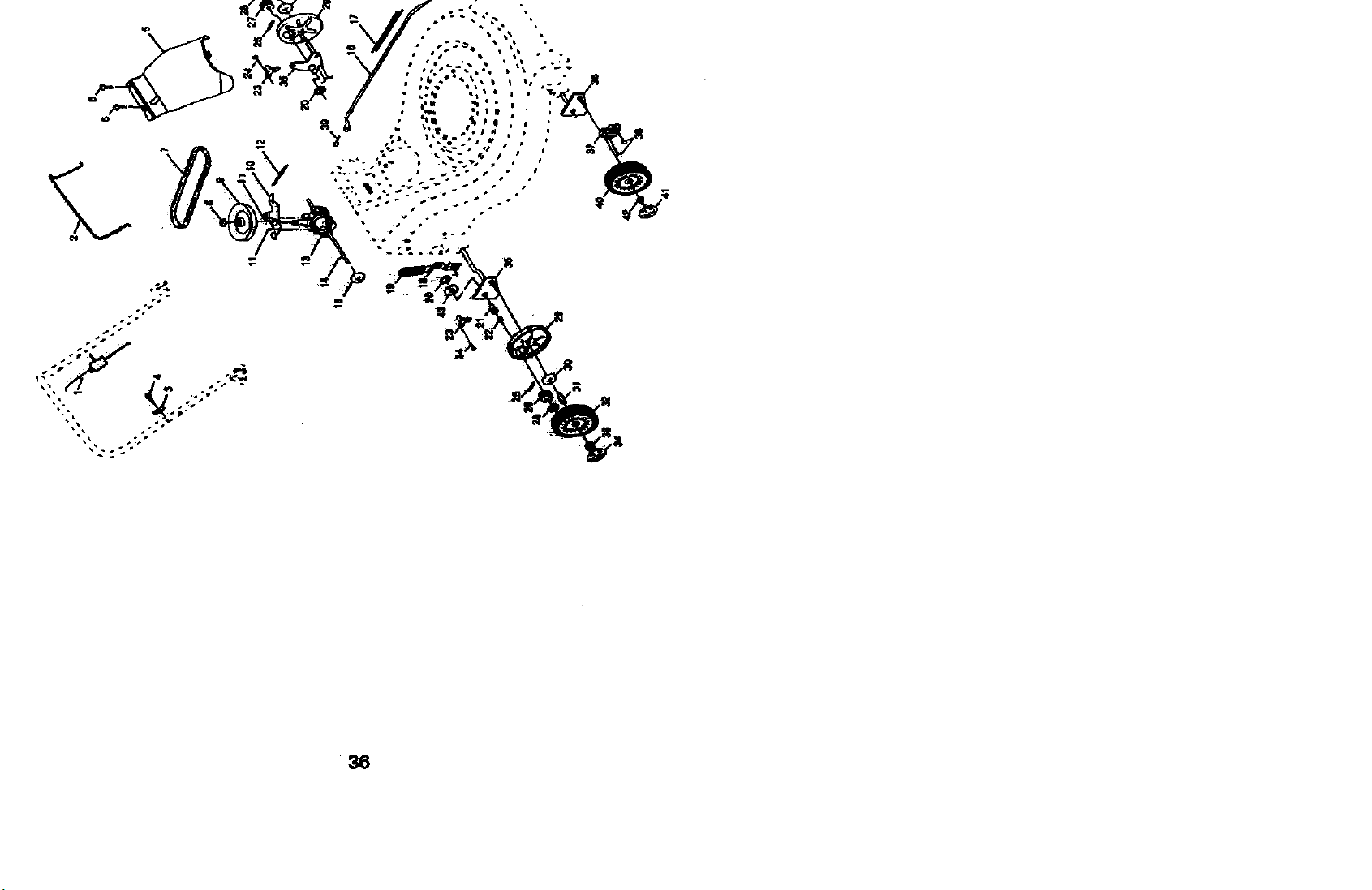
ROTARY LAWN MOWER - - MODEL NO. 917.377631
84
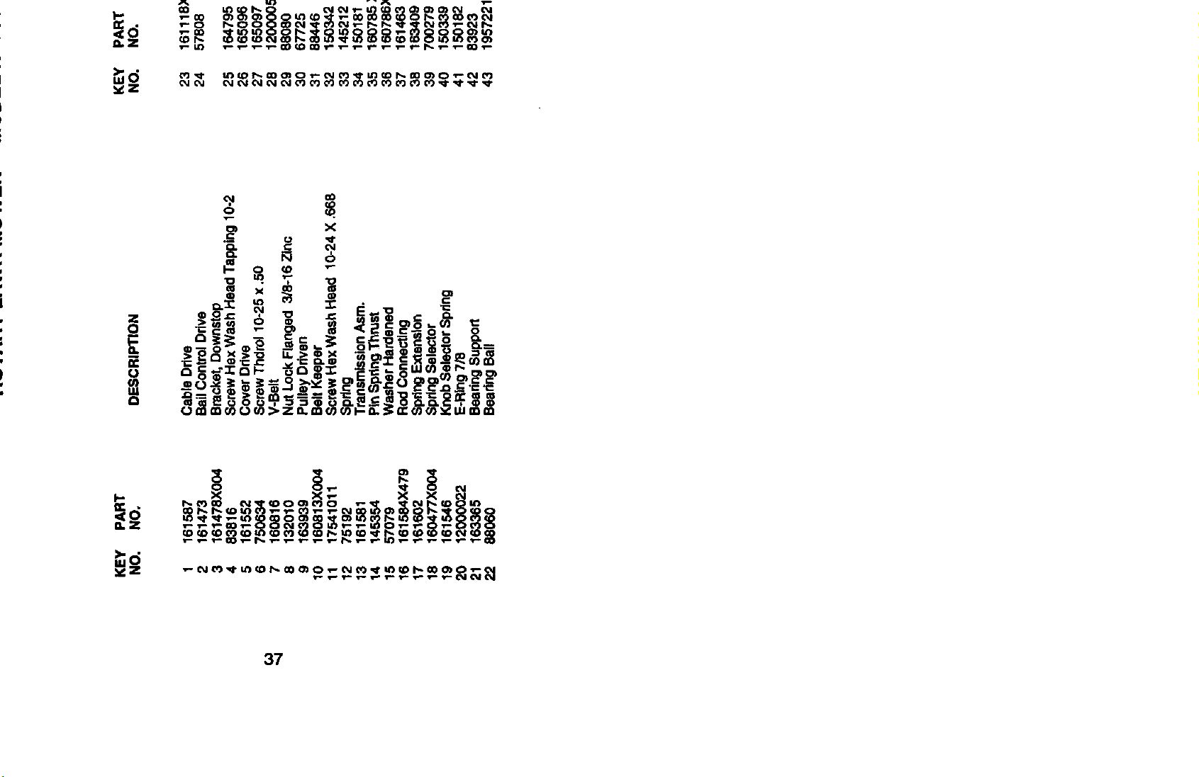
ROTARY LAWN MOWER - - MODEL NO. 917.377631
KEY PART
NO. NO.
KEY PART
DESCRIPTION NO. NO.
DESCRIPTION
(o
",4
1 161587
2 161473
3 161478X004
4 83816
5 161552
6 750634
7 160816
8 132010
9 163939
10 160813X004
11 17541011
12 75192
13 161581
14 145354
15 57079
16 161584X479
17 161602
18 160477X004
19 161546
20 12000022
21 163365
22 88O6O
Cable Drive 23 161118X004
BailControl Drive 24 57808
Bracket, Downstop
Screw Hex Wash Head Tapping 10-2 25 164795
Cover Drive 26 165096
Screw Thdro110-25 x .50 27 165097
V-Belt 28 12000058
Nut Lock Flanged 3/8-16 Zinc 29 88080
Pulley Driven 30 67725
Belt Keeper 31 88446
Screw Hex Wash Heed 10-24 X .668 32 150342
Spdng 33 145212
TransmissionAsm. 34 150181
Pin SpdngThrust 35 160785 X004
Washer Hardened 36 160786X004
Rod Conne_"ting 37 161463
Spring Extension 38 163409
Spring Selector 39 700279
Knob Selector Spring 40 150339
E-Ring 7/8 41 150182
Beadng Support 42 83923
Searing Ball 43 19572216
Retainer Drive Asm. Stmp,
Screw He:<Head Tapping 1/4-20
x .75
Drive Pawl
Pinion,Odve P-H
Pinion,Dde LH
E-Ring 7/16
Cover, Dust Wheel
Washer 1/2 x 1-1/2 x.134
Bushing
Wheel 9 x 2
Nut Hex Flange Lock
Hubcap, Mag Platinum9"
Shaft Asm. Rear
Shaft Asm. Front
Retainer FrontShaft
Screw 12 x 5/8
Clip Retainer
Wheel 8 x 2
Hubcap, Mag Platinum8"
Nut, Hex Flange Lock 3/6-16
Washer
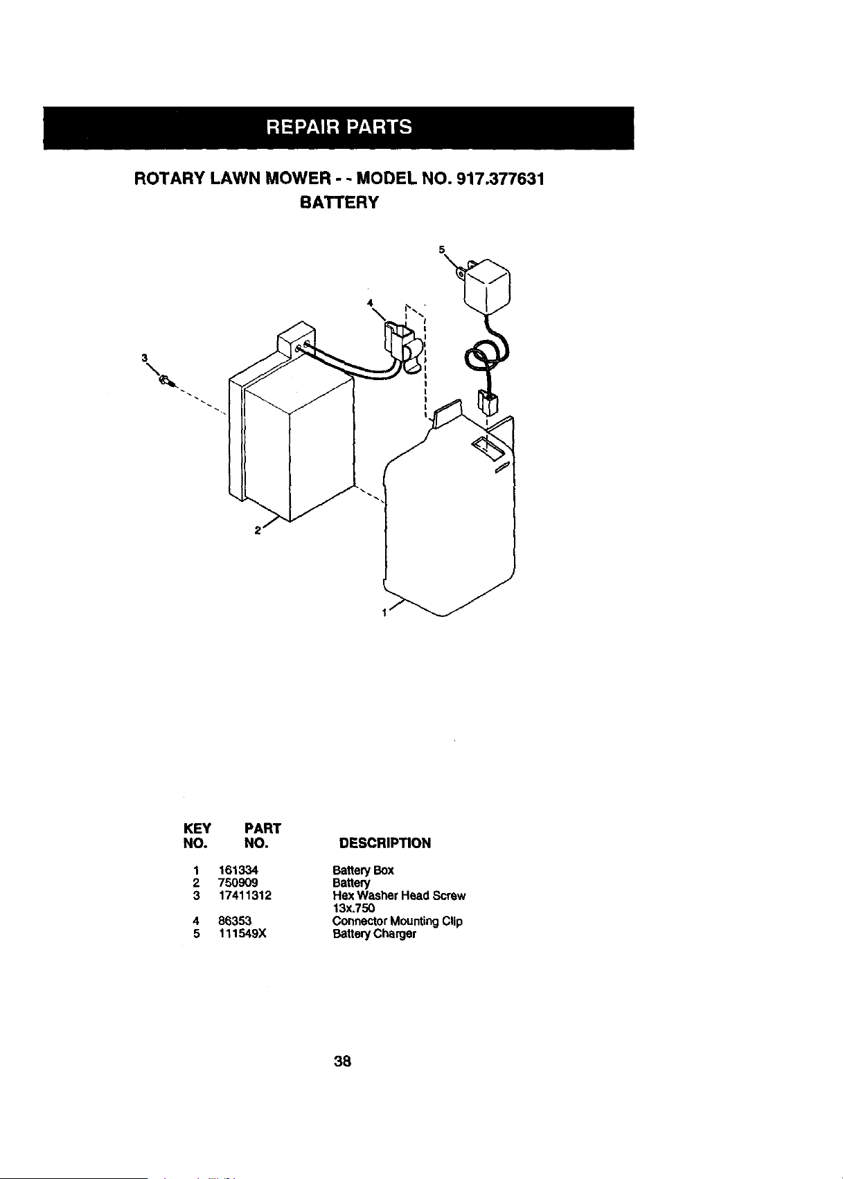
ROTARY LAWN MOWER - - MODEL NO. 917.377631
BATTERY
5
3
\
4
KEY PART
NO. NO. DESCRIPTION
1
2
3
161334 Battery Box
750909 Battery
17411312 Hex Washer Head Screw
13x.750
86353 Connector MountingClip
111549X Battery Charger
38

39
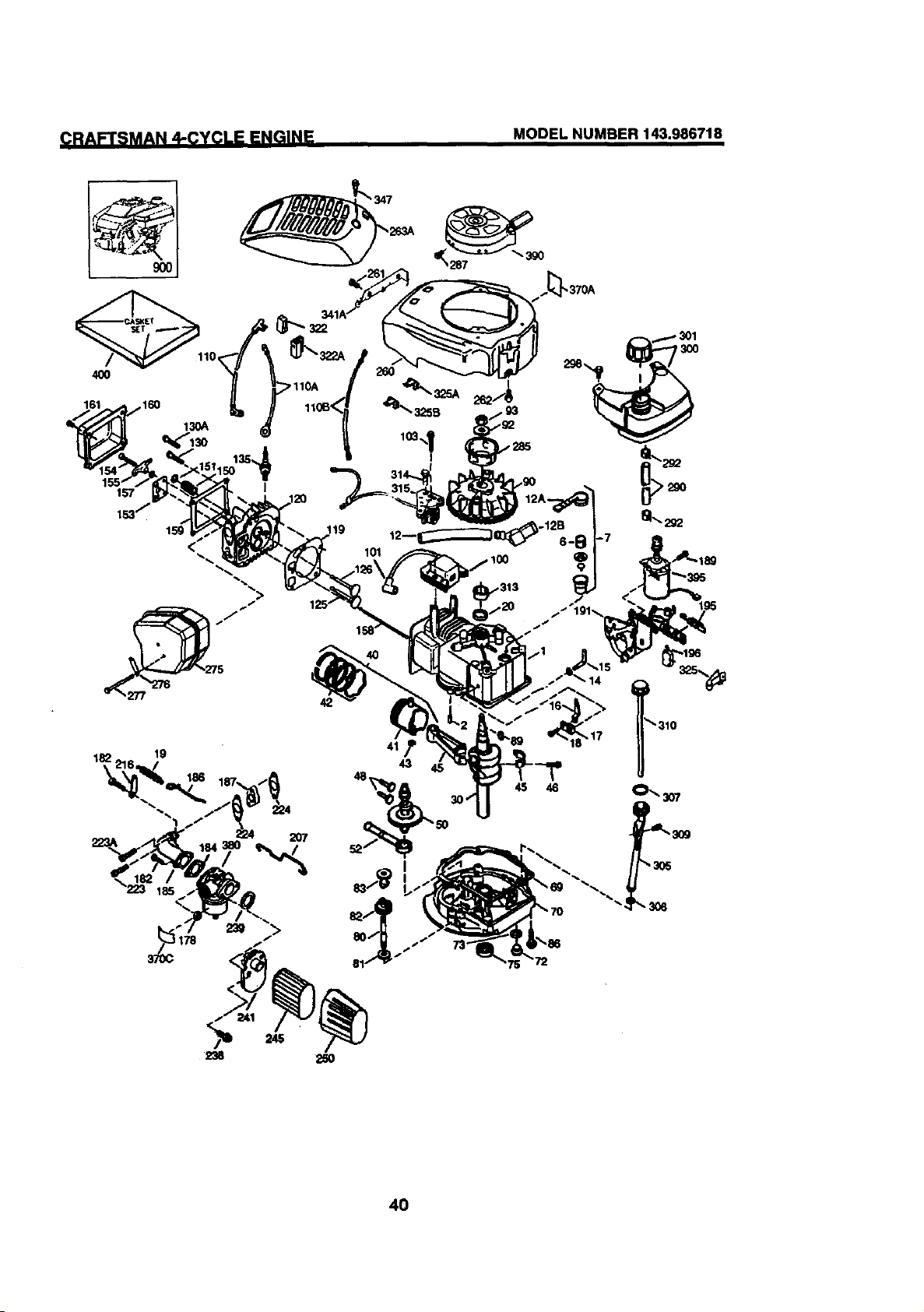
(_Rp,FTSMAN 4-CYCLE ENGINE MODEL NUMBER 143.986718
_370A
4O
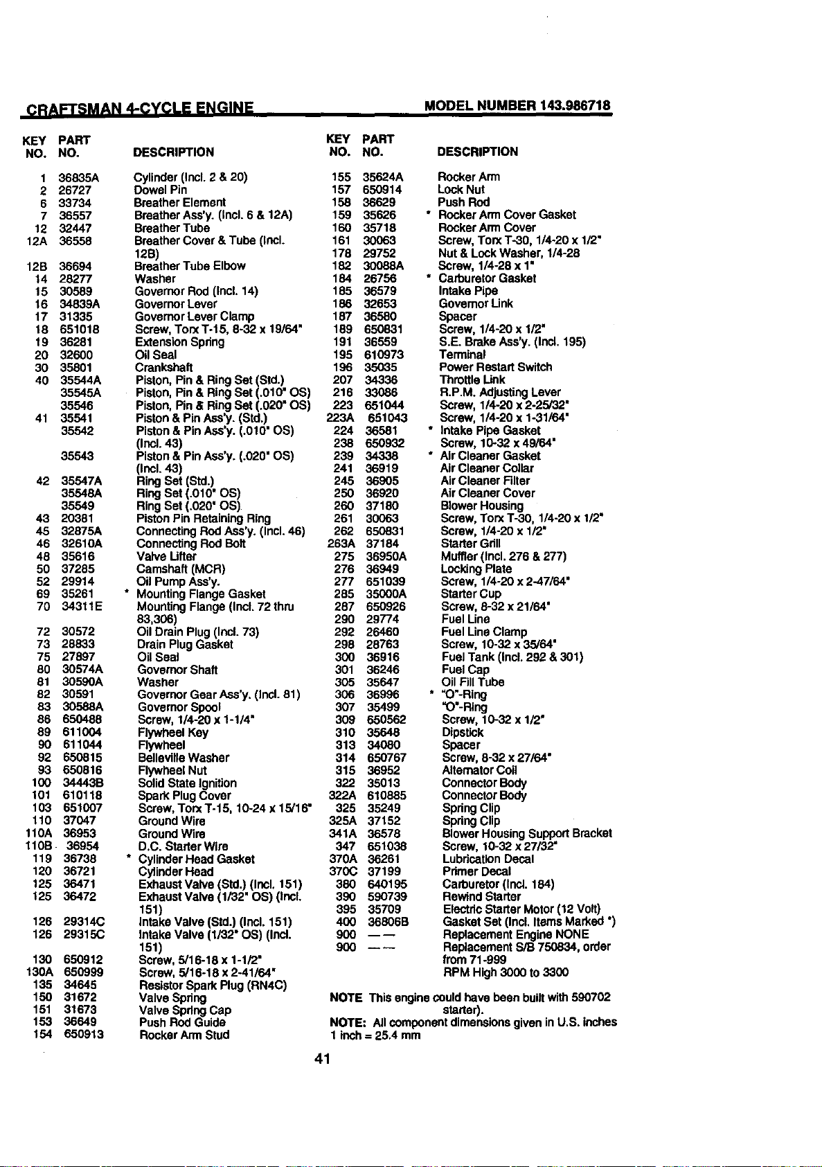
CRAFTSMAN 4-CYCLE ENGINE MODEL NUMBER 143.986718
KEY PART
NO. NO. DESCRIPTION
1 36835A
2 26727
6 33734
7 36557
12 32447
12A 36558
12B 36694
14 28277
15 30589
16 34839A
17 31335
18 651018
19 36281
20 32600
30 35801
40 35544A
35545A
35546
41 35541
35542
35543
42 35547A
35548A
35549
43 20381
45 32875A
46 32610A
48 35616
50 37285
52 29914
69 35261
70 34311E
72 30572
73 28833
75 27897
80 30574A
81 30590A
82 30591
83 30588A
66 650488
89 611004
90 611044
92 650815
93 650816
100 34443B
101 610118
103 651007
110 37047
110A 36953
110B 36954
119 36738
120 36721
125 36471
125 36472
126 29314(3
126 29315C
130 650912
130A 650999
135 34645
150 31672
151 31673
153 36649
154 650913
KEY PART
NO. NO. DESCRIPTION
Cylinder (Incl. 2 & 20) 155 35624A Rocker Arm
Dowel Pin 157 650914 LockNut
Braather Element 158 36629 Push Rod
Braather Ass'y. (Incl. 6 & 12A) 159 35626 • Rocker Arm Cover Gesket
Breather Tube 160 35718 Rocker Arm Cover
Braather Cover & Tube (Incl. 161 30063 Scraw, Torx T-30, 1/4-20 x 1/2"
12B) 178 29752 Nut & Lock Wesher, 1/4-28
Braather Tube Elbow 182 30088A Scraw, 1/4-28 x 1"
Washer 184 26756 * Carburetor Gasket
Governor Rod (IncL 14) 185 36579 Intake Pipe
Governor Lever 186 32653 Govemor Link
Govemor Lever Clamp 187 36580 Spacer
Screw, Torx T-15, 8-32 x 19/64" 189 650831 Screw, 1/4-20 x 1/2"
Extension Spring 191 36559 S.E. Brake Ass'y. (Incl. 195)
Oil Seal 195 610973 Terminal
Crankshaft 196 35035 Power Restart Switch
Piston, Pin & Ring Set (Std.) 207 34336 "l_rottle Link
Piston, Pin & Ring Set (.010" OS) 216 33086 R.PM. AdjustingLever
Piston, Pin & Ring Set (.020" OS) 223 651044 Screw, 1/4-20 x 2-25/32"
Piston & Pin Ass',/. (Std.) 223A 651043 Screw, 1/4-20 x 1-31/64"
Piston & Pin Ass'y. (.010" OS) 224 36581 * Intake Pipe Gasket
(Inol. 43) 238 650932 Scraw, 10-32 x 49/64"
Piston & Pin Ass'),. (.020" OS) 239 34338 * Air Cleaner Gasket
(Incl. 43) 241 36919 Air Cleaner Collar
RingSet (Std.) 245 36905 AirClesner Filter
RingSet (.010" OS) 250 36920 Air Cleaner Cover
RingSet (.020" OS) 260 37180 Blower Housing
PistonPin Retaining Ring 261 30063 Screw, Torx T-30, 1/4-20 x 1/2"
Connecting Rod Ass'y. (Incl. 46) 262 650831 Screw, 1/4-20 x 1/2'
Connecting ROdBolt 263A 37184 Starter Gdll
Valve Lifter 275 36950A Muffler (Incl. 276 & 277)
Camshaft (MCR) 276 36949 LockingPlate
Oil Pump Ass'y. 277 651039 Screw, 1/4-20 x 2-47/64"
• MountingFlange Gasket 285 35000A Starter Cup
Mounting Flange (Incl.72 thru 287 650826 Screw, 8-32 x 21/64"
83,306) 290 29774 Fuel Line
OilDrain Plug (Incl. 73) 292 26460 Fuel Line Clamp
Drain Plug Gasket 298 28763 Scraw, 10-32 x 35/64"
Oil Seal 300 36916 Fuel Tank (IncL292 & 301)
Governor Shaft 301 36246 Fuel Cap
Washer 305 35647 Oil Fill Tube
Governor Gear Ass'y. (Incl. 81) 306 36996 * _O'-Ring
Governor Spool 307 35499 =O'-RIng
Screw, 1/4-20 x 1-1/4" 309 650562 Screw, 10-32 x 1/2"
Flywheel Key 310 35648 Dipstick
Flywheel 313 34080 Spacer
BellevilleWasher 314 650767 Screw, 8-32 x 27/64"
Flywheel Nut 315 36952 Aitemator Coil
Solid State Ignition 322 35013 Connector Body
Spark Plug Cover 322A 610885 Connector Body
Scraw, TorxT-15, 10-24x15/16" 325 35249 SpdngClip
GroundWira 325A 37152 Spdng Clip
GrouodWire 341A 36578 Slower HousingSupport Bracket
D.C. StarterWira 347 651038 Screw, 10-32 x27/32"
• CylinderHaad Gasket 370A 36261 LubricationDecal
CyfinderHead 370C 37199 Primer Decal
ExhaustValvs(Std.)(Incl. 151) 380 640195 Carburetor(Incl. 184)
Exhaust Valve (1/32" OS) (thcL 390 590739 Rewind Starter
151) 395 35709 Electdc Starter Motor (12 Volt)
Intake Valve (Std.) (Incl. 151) 400 36806B Gasket Set (IncL Items Marked ")
Intake Valve (1/32" OS) (Ind. 900 ---- Replacement Engine NONE
151) 900 ---- Replacement S/B 750834, order
Screw, 5/16-18 x 1-1/2" from 71-999
Screw, 5/16-18 x 2-41/64" RPM High 3000 to 3300
Resistor Spark Plug (RN4C)
Valve Spring NOTE This engine could have been builtwith590702
Valve Spdng Cap starter).
Push Rod Guide NOTE: All component dimensionsgiven in U.S. inches
Rocker Arm Stud 1 inch = 25.4 mm
41
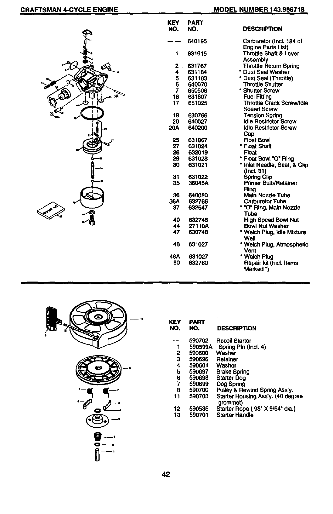
CRAFTSMAN 4-CYCLE ENGINE MODEL NUMBER 143.986718
?--,,
KEY
NO.
2
4
5
6
7
16
17
18
20
20A
25
27
28
29
30
31
35
36
36A
37
40
44
47
48
48A
6O
PART
NO.
640195
631615
631767
631184
631183
640070
650506
631807
651025
630766
640027
64O2OO
631867
631024
632019
631028
631021
631022
36O45A
640O80
632766
632547
632746
27110A
630748
631027
631027
63276O
DESCRIPTION
Carburetor(Incl. 184 of
Engine Parts List)
Throttle Shaft & Lever
Assembly
Throttle Rstum Spdng
* Dust Seal Washer
* Dust Seal (Throttle)
Throttle Shutter
• Shutter Screw
Fuel Fitting
Throttle Crack Screw/Idle
Speed Screw
Tension Spdng
Idle Restdctor Screw
Idle Resistor Screw
Cap
Float Bowl
* Float Shaft
Roat
* Float Bowl "O" Ring
* Inlet Needle, Seat, & Clip
(ind. 31)
Spring Clip
Pdmer Bulb/Retainer
Ring
Main Nozzle Tube
CarburetorTube
""0" Ring, Main Nozzle
Tube
High Speed Bowl Nut
Bowl NutWasher
* Welch Plug, Idle Mixture
Well
• Welch Plug, Atmospheric
Vent
* Welch Plug
Repair kit(Incl. Items
Marked *}
KEY
NO.
1
2
3
4
5
6
7
6
11
12
13
PART
NO.
590702
590599A
59O6OO
59O696
590601
590697
590698
590699
590700
590703
590535
590701
DESCRIPTION
Recoil Starter
Spring Pin (Incl. 4)
Washer
Retainer
Washer
Brake Spring
Starter Dog
Dog Spdng
Pulley & Rewind Spring Ass'y.
Starter HousingAss'y. (40 degree
grommet)
Starter Rope ( 98" X 9/64" dia.)
Starter Handle
42
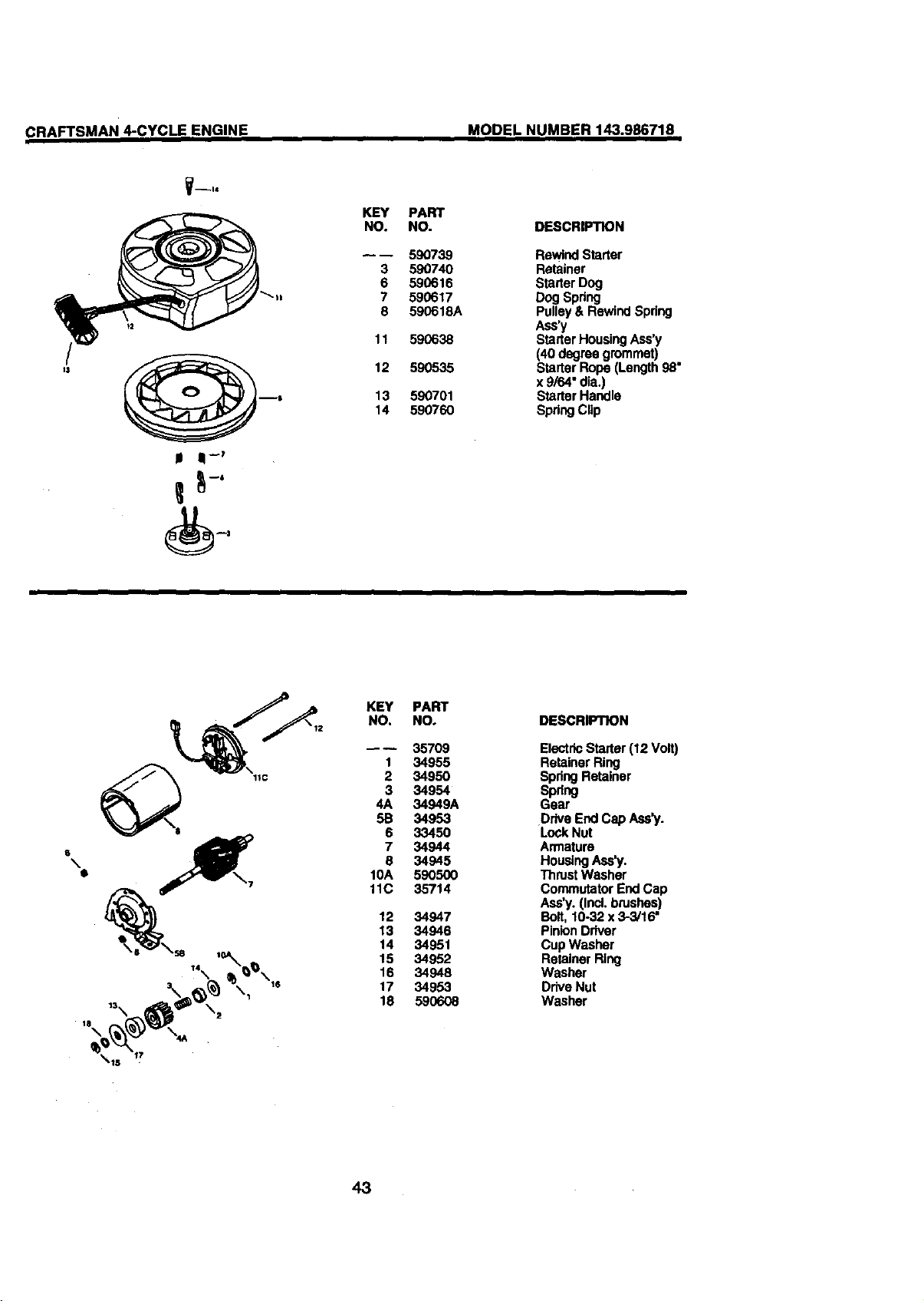
CRAFTSMAN 4-CYCLE ENGINE MODEL NUMBER 143.986718
V--hi
II II -_
KEY
NO.
3
6
7
8
11
12
13
14
PART
NO.
59O739
590740
590616
590617
590618A
590638
590535
590701
590760
DESCRIPTION
Rewind Starter
Retainer
Starter Dog
Dog Spring
Pulley & Rewind Spring
Ass'y
Starter HousingAss'y
(40 degree grommet)
Starter Rope (Length 98"
x 9/64" dia.)
Starter Handle
Spring Clip
2
KEY
NO.
1
2
3
4A
5B
6
7
8
10A
11C
12
13
14
15
16
17
18
PART
NO.
357O9
34955
34950
34954
34949A
34953
33450
34944
34945
59O5OO
35714
34947
34946
34951
34952
34948
34953
59O6O8
DESCRIPTION
Electric Starter (12 Volt)
Retainer Ring
Spdng Retainer
Spring
Gear
Drive End Cap Ass'y.
LockNut
Armature
HousingAss'y.
Thm_ Washer
Commutator End Cap
Ass'y. (Incl. brushes)
Bolt, 10-32 x 3-3/16"
Pinion Driver
Cup Washer
Retainer Ring
Washer
Drive Nut
Washer
43
For the repair or replacement parts you need
delivered directly to your home
Call 7 am - 7 pm, 7 days a week
1-800-366-PART
(1-800-366-7278)
Para ordenar piezas con entrega a
domicilio - 1-800-659-7084
For in-house major brand repair service
Call 24 hours a day, 7 days a week
1-800-4-REPAIR
(1-800-473-7274)
Para pedir servicio de reparacldn a
domicilio - 1-800-676-5811
For the location of a Sears Parts and
Repair Center in your area
Call 24 hours a day, 7 days a week
1-800-488-1222
ERIUml
m|m||
For information on purchasing a Sears
Maintenance Agreement or to inquire
about an existing Agreement
Call 9 am - 5 pm, Monday-Saturday
1-800-827-6655
When request',ng service ol"ordering
parts, always provide the following
information:
• Product Type • Part Number
, Model Nurpber • Part Description
SEARS
Arnenca's Repazr Spec_atzsrs
165683 REV.1 01.28.99 VB Pdnted in U.S.A.