C
ARE & USE
/
INSTALLATIO
N
MAKE THE MOST OF YOUR

2
|
INSTALLATION / USE & CARE
WARNINGS
WARNING
This product complies with ANSI standard Z21.58/CSA 1.6
latest edition and has been tested and approved by Intertek.
To obtain replacement parts or service contact:
Lynx Grills
62201 Hwy 82 West
Greenwood, Mississippi 38930
Service: (888) 289-5969
• Never use dented, rusty or damaged propane cylinders. Never store additional or empty propane
cylinders in the grill cabinet or in the vicinity of this or any other appliance. Do not store propane
cylinders indoors or on their sides.
• Children should never be left alone or unattended in an area where a grill is located. Place your
grill well away from areas where children play. Do not store items that may interest children in or
around the grill, in the cart, or in the masonry enclosure.
• Never move the grill when hot. When in use, portions of the grill are hot enough to cause severe
burns.
• Always maintain the required clearances from combustibles as detailed. The grill is designed for
outdoor use only. Never use in a garage, building, shed, breezeway, or other enclosed area. Do not
use this grill under any unprotected overhead combustible construction.
• Gas grills are not designed or certifi ed for and are not to be installed in or on recreational vehicles,
portable trailers, boats or any other moving installation.
• Always have an ABC Fire Extinguisher accessible — never attempt to extinguish a grease fi re with
water or other liquids.
• Storing your grill: Store your grill in a well-ventilated area. If stored indoors, detach and leave L.P.
cylinder outdoors in a well-ventilated area away from heat and away from where children may
tamper with it.
• Keep any electrical supply cord and the fuel supply hose away from any heated surfaces. Electrical
cords should be placed away from walkways to avoid tripping hazard.
• Do not repair or replace any part of the grill unless specifi cally recommended in this manual. Other
service should be performed by a qualifi ed technician.
• If the grill is installed by a professional installer or technician, be sure that he/she shows you where
your gas supply shut-o is located. All gas lines must have a shut-o that is readily and easily
accessible. If you smell gas, check for gas leaks immediately. Check only with a soap and water
solution. (See INDEX: “Leak Testing” for further details.) Never check for gas leaks with an open
fl ame.
• Inspect the L.P. gas supply hose prior to each use of the grill. If there is evidence of excessive
abrasion or wear, or the hose is cut, it must be replaced before using the grill.
• Never remove the grounding prong from the plug or use this product with an ungrounded, 2-prong
adapter.
• Installation must conform with local codes or, in the absence of local codes, with either the National
Fuel Gas Code, ANSI Z223.1/NFPA 54, Natural Gas and propane Installation Code, CSA B149.1, or
Propane Storage and Handling Code, B149.2, in Canada.
THIS MANUAL MUST REMAIN WITH THE PRODUCT OWNER FOR FUTURE REFERENCE.
INSTALLATION / USE & CARE
|
3
WARNINGS
READ THIS MANUAL CAREFULLY and completely before using your grill to reduce the risk of:
1. Fire
2. Burn hazard, personal injury or property damage
3. Ruined steaks or other unpleasant cooking experiences
4. Unapproved installation or servicing.
THIS PRODUCT IS DESIGNED FOR OUTDOOR USE ONLY. Improper installation, adjustment, alteration,
service or maintenance can cause property damage, injury or death.
Read this manual thoroughly before installation, use, or servicing of this product.
IF YOU SMELL GAS:
1. Shut o all gas supply lines to the grill.
2. Extinguish any open fl ames.
3. Carefully open the lid. Remember, it may be
extremely hot!
4. If odor continues, keep everyone away
from the grill and immediately call your gas
supplier or your fi re department.
1. DO NOT store or use gasoline or other
fl ammable vapors and liquids in the
vicinity of this or any other appliance.
2. An LP cylinder not connected for use shall
not be stored in the vicinity of this or any
other appliance.
WARNING
DANGER
WARNING
1. Coupex l’admision de gaz de l’appariel.
2. Éteindre toute fl amme nue.
3. Ouvir le couvercle!
4. Si l’odeur persiste, éloignez-vous de
l’appareil et appelez immédiatement le
fournisseur de gaz ou le service d’incendie.
DANGER
1. NE PAS entreposer ni utilioser de
i’essence ni d’autres vapeurs ou liquides
infl ammables dans le voisinage de
l’appareil, ni de tout autre appareil.
2. Une bouteille de propane qui n’est ps
raccordée en vue de son utilisation, ne doit
pas être entreposée dans le voisinage de
cet appareil ou de tout autre appareil.
AVERTISSMENT
S
’IL Y A UNE ODEUR DE GAZ:
4
|
INSTALLATION / USE & CARE
WARNINGS
WARNING
STATE OF MASSACHUSETTS
1. Massachusetts requires all gas be installed using a plumber or gas fi tter carrying the appropriate
Massachusetts license.
2. All permanently-installed natural gas or propane installations require a “T” handle type manual gas
valve be installed in the gas supply line to this appliance.
3. This does not apply to portable propane installations using a 20 pound cylinder.
1. The outdoor cooking gas appliance and its individual shuto valve must be disconnected from the gas
supply piping system during any pressure testing of that system at test pressures in excess of 0.5 psi
(3.5 kPa).
2. The outdoor cooking gas appliance must be isolated from the gas supply piping system by closing
its individual manual shuto valve during any pressure testing of the gas supply piping system at test
pressures equal to or less than 1/2 psi (3.5 kPa).
WARNING
1. Always maintain the required clearances from combustible construction as detailed. The grill is
designed for outdoor use only. Never use in a garage, building, shed, breezeway or other enclosed
area. This grill shall not be used under any unprotected overhead combustible construction.
2. Gas grills are not design certifi ed for and are not to be installed in or on recreational vehicles, portable
trailers, boats or any other moving installation.
3. Keep any electrical supply cord and the fuel supply hose away from any heated surfaces. Electrical
cords should be placed away from walkways to avoid creating a tripping hazard.
4. Do not repair or replace any part of the grill unless specifi cally recommended in this manual. Other
service should be performed by a qualifi ed technician.
5. All gas lines must have a shut-o that is readily and easily accessible. Be sure the owner knows
where the shut-o is located. If you smell gas, check for gas leaks immediately. Check only with a
soap and water solution. Never check for gas leaks with an open fl ame. (See INDEX: “Leak Testing”
for further details.)
6. Never locate the grill under a roof or overhang, in a building, garage, shed or other such enclosed
area.
7. Never locate the grill under unprotected combustible construction.

INSTALLATION / USE & CARE
|
5
BEFORE YOU START 6
If Shipment Arrives Damaged 6
Important Notes 6
SPECIFICATIONS & INSTALLATION 8
UNPACKING & ASSEMBLY 16
GAS CONNECTIONS 18
Natural Gas 18
LP Gas 19
Gas Conversion Kits 20
ELECTRICAL CONNECTIONS 22
FINAL CHECKS 23
Leak Testing 23
CHECKLIST BEFORE EACH USE 24
A MESSAGE TO OUR CUSTOMERS 25
IMPORTANT SAFETY PRECAUTIONS 25
GRILLING IN WINDY CONDITIONS 26
USING YOUR GRILL 26
Pre-Grill Checklist 27
Lighting your Grill 27
Basic Grilling 29
Using the ProSear™ Burner 30
Using the Rotisserie Burner 31
Using the Smoker Box 31
CLEANING YOUR GRILL 32
TROUBLESHOOTING YOUR GRILL 34
Potential Problems 34
CONTACTING CUSTOMER SERVICE 37
OUTDOOR WARRANTY 38
WIRING SCHEMATICS 40
30 Rotisserie Grill 40
36 & 42 Rotisserie Grill 41
54 Rotisserie Grill 42
TABLE OF CONTENTS
6
|
INSTALLATION / USE & CARE
VISIBLE LOSS OR DAMAGE
Be certain any visible damage to the carton is noted on
freight bill or express receipt and signed by the person
making delivery.
FILE CLAIM FOR DAMAGES IMMEDIATELY, regardless of
extent of damage.
CONCEALED LOSS OR DAMAGE
If damage is unnoticed until the grill is unpacked, notify the
transportation company or carrier immediately and fi le a
“concealed damage” claim with them. This should be done
within (15) days of the date delivery is made to you. Be sure
to hold on to the container for inspection. We cannot assume
responsibility for damage or loss incurred in transit. (See
Installation into a combustible enclosure requires an insulated jacket accessory. DO NOT REMOVE
BRACKET OR INSTALL UNIT without use of the insulated jacket. Doing so may result in a fi re, injury or
property damage. Bracket must be removed to complete install with insulated jacket.
Insulated jackets may be ordered at [email protected] or phone 888-845-4641 press 1.
Please have grill model and serial available when ordering.
BEFORE YOU START
WARNING
IF SHIPMENT ARRIVES DAMAGED
INDEX: “Obtaining Service” for further details.
)
IMP
O
RTANT N
O
TE
S
WHERE’S THE WIND
?
When selecting a suitable location, consider important
f
actors such as exposure to the wind and
f
oot-tra
c patterns
.
If you have a freestanding grill, position it so the prevailing
wind blows into the front control panel
(
at your back when
grilling
)
, supporting the proper front-to-rear airfl ow
.
B
ui
l
t-in
g
ri
ll
s
l
ocate
d
in areas wit
h
prevai
l
in
g
win
d
s s
h
ou
ld
b
e
protecte
d
by
a win
d
b
arrier.
Winds hittin
g
the
b
ac
k
o
f
the
g
rill directl
y
ma
y
cause
e
ms, as well as
d
blowin
g
alon
g
h
oo
d
ga
p
.
H
O
W L
O
N
G
IS Y
O
UR RUN
?
K
eep a
ll
g
as supp
ly
l
ines as s
h
ort as possi
bl
e
b
ecause
g
as
l
ines
l
ose pressure over
d
istance an
d
wit
h
eac
h
e
lb
ow
an
d
tee t
h
at
i
s a
dd
e
d
.
Thi
s
d
rop
i
n pressure a
ects
g
r
ill
performance. (See INDEX: “Gas Supply Line Runs” for further
details.
)
ARE YOU “ON-THE-LEVEL”?
Proper leveling during installation is critical. A grill that is out
o
f
level will cause erratic burner combustion and ine
cient,
uneven heating. A carpenter
’
s spirit level should be used to
level the grill both
f
ront-to-back and side-to-side.
I
f
the
fl
oor is uneven or has a decided slope, re-leveling may
be required each time you move a
f
reestanding unit
.
proble
win
d
t
he
p
p
pe
rf
o
or
ma
n
nc
e. (See INDEX:
Ga
a
s
S
Su
pply
L
L
ine Ru
n
ns
for
fu
u
rthe
d
h
h
i
d
d
d
T
hi
d
i
i
i
ll
Be sure wind doesn’t blow into the hood gap.
INSTALLATION / USE & CARE
|
7
BUILT-IN INSTALLATIONS
This built-in grill is designed for easy installation into
masonry enclosures.
NOTE: Built-in grills are intended either for installation in a
built-in enclosure constructed of non-combustible materials
or for an installation in a built in enclosure constructed of
combustible material when installed with a insulating jacket).
For non-combustible applications, the grill drops into the
opening shown in the cutout detail drawing (See INDEX:
“Gas Requirements”) and hangs from its counter-top trim. A
deck is not required to support it from the bottom.
When using the insulated jacket in a combustible enclosure,
the jacket must be supported from the bottom by a ledge on
each side or a full deck beneath the jacket.
(See INDEX: “Gas Requirements”) Pay special attention to the
provisions shown for gas line hook-up.
The enclosure should have ventilation holes to prevent gas
build-up in the event of a leak. The deck ledges and counter
should be fl at and level. (refer to ANSI Z21.58 Standard for
Outdoor Cooking Gas Appliances, Section 1.7 Enclosures For
Self Contained LP-Gas Supply Systems)
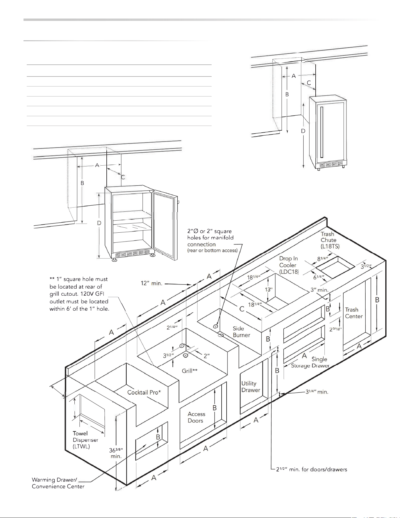
This grill requires that a 120 volt, 60 hertz, 15 amp GFI
certifi ed outlet be installed by a qualifi ed electrician.
CLEARANCE TO COMBUSTIBLE MATERIALS
Minimum clearance from the sides and back of the grill to
adjacent combustible construction below the counter top
surface is 12” from the sides and 6 1/4” from the back of the
hood.
Dégagement minimal entre les parios latérales et l’arrière de l’appariel et la
constructiohn combustible au-dessous de panneau supérieur de l’appariel (30 cm à
partir des parois latérales et 15.9 cm à partir de l’arrière de la hotte).
Minimum clearance from sides and back of grill to adjacent
combustible construction extending above the counter top
surface is 12” from the sides and 6 1/4” from the back.
Dégagement horizontal minimal entre les parios latérales et l’arrière de l’appariel
et la constructiohn verticale combustible au-dessous de panneau supérieur de
l’appariel (30 cm à partir des parois latérales et 15.9 cm à partir de l’arrière de
la hotte).
Do not use this appliance under unprotected overhead
combustible surfaces.
N’utilisez pas cet appareil sous des surfaces infl ammables non protégées
A minimum of 6” of clearance is needed on the left side of
the grill above the counter top for the motor and skewer.
If the grill is to be placed into a combustible enclosure, an
approved insulated jacket is necessary and is available only
from your Lynx dealer. Insulated jackets have been designed
and tested specifi cally for your grill.
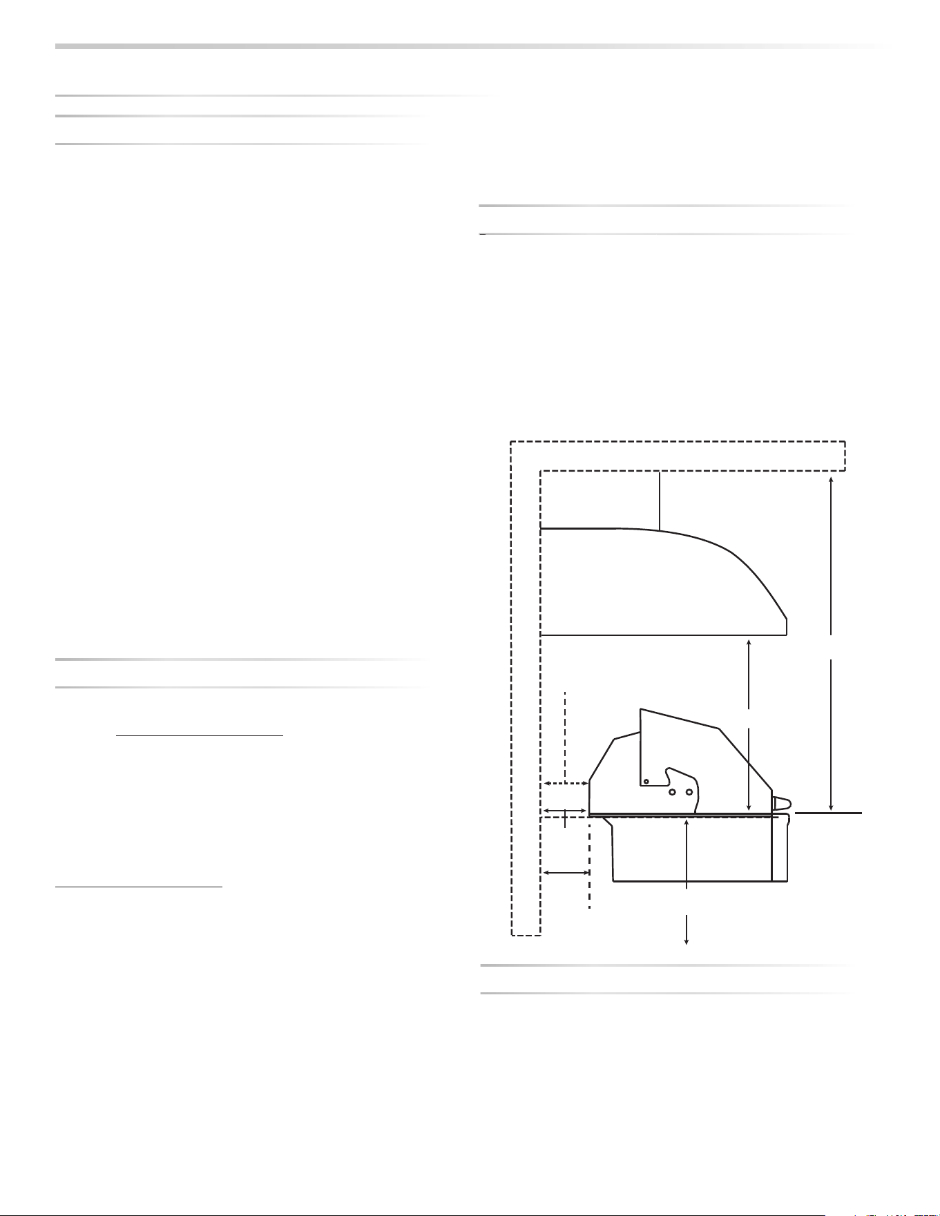
REAR HOOD CLEARANCE
A 3 inch clearance is required behind the grill to allow the
front hood to open.
The grill exhausts combustion products and cooking greases
to the back. Never locate the grill where this exhaust will be
di cult to clean.
OVERHEAD PROTECTION AND EXHAUST REMOVAL
If installed under any combustible construction the cooking
area over the grill must be covered with an exhaust hood.
The hood must provide 3 - 6” of overhange on all exposed
sides. The exhaust hood shall provide no less than 1,200
CFM for proper exhaust ventilation. The hood must be
approved for outdoor installation and provided with a
dedicated GFCI protected branch circuit.
BEF
O
RE Y
OU
S
TART
...
co
n
t
in
u
e
d
R
RE
AR
R
H
O
OO
D
C
CL
EARANCE
Vent Hood
Overhead Construction
R
e
a
r
W
a
l
l
3” overhang on left and right side of grill
36” Minimum
6’ Minimum to
non-combustible
6 1/4” Clearance from the
grill back to above
counter combustibles
3”
Minimum
hood
clearance
12” clearance to combustibles from
surface level right/left/below
Combustible overhead
construction requires a
vent hood
Non-combustible overhead
construction a vent hood is
highly recommended
6 1/4”
Minimum
clearance
to combustibles
8
|
INSTALLATION / USE & CARE
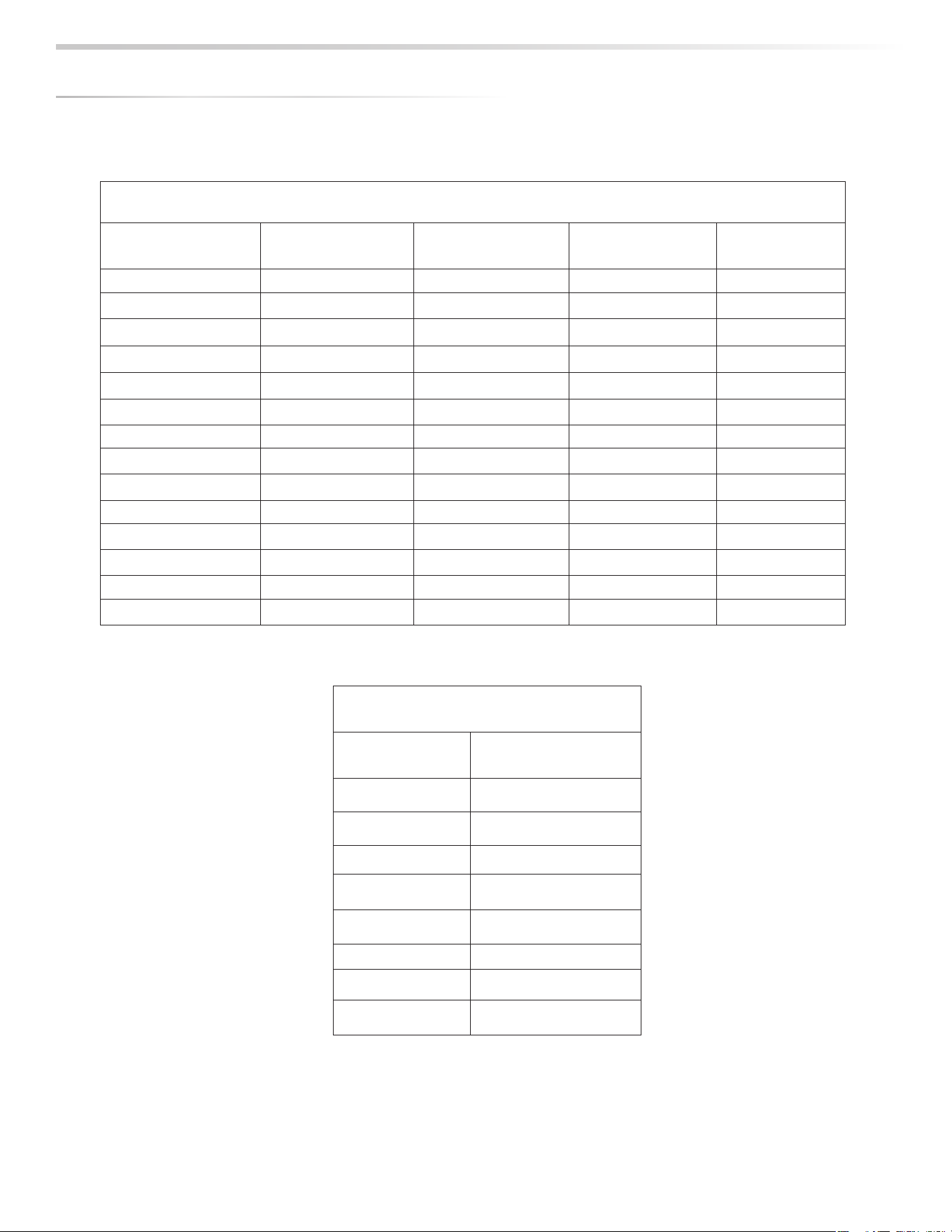
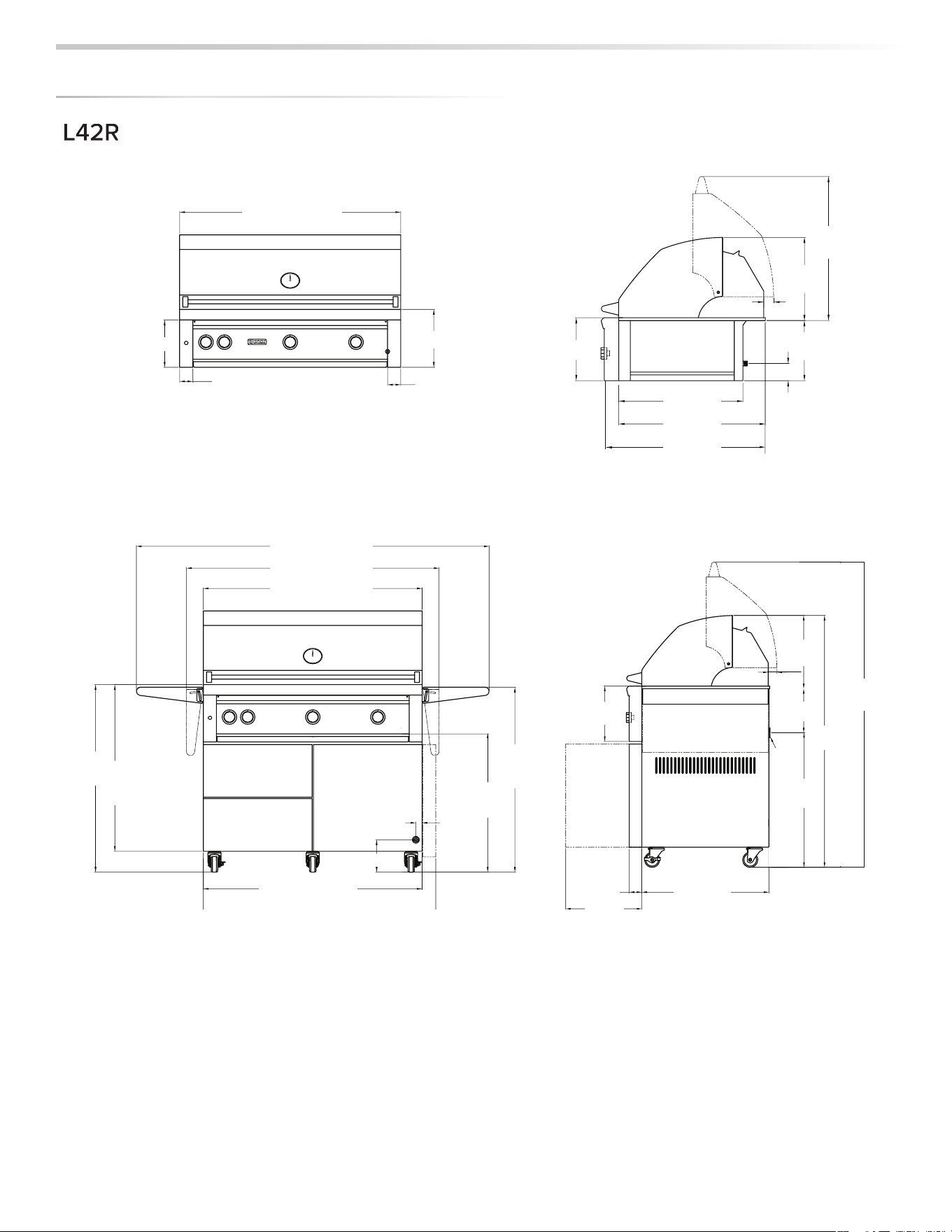
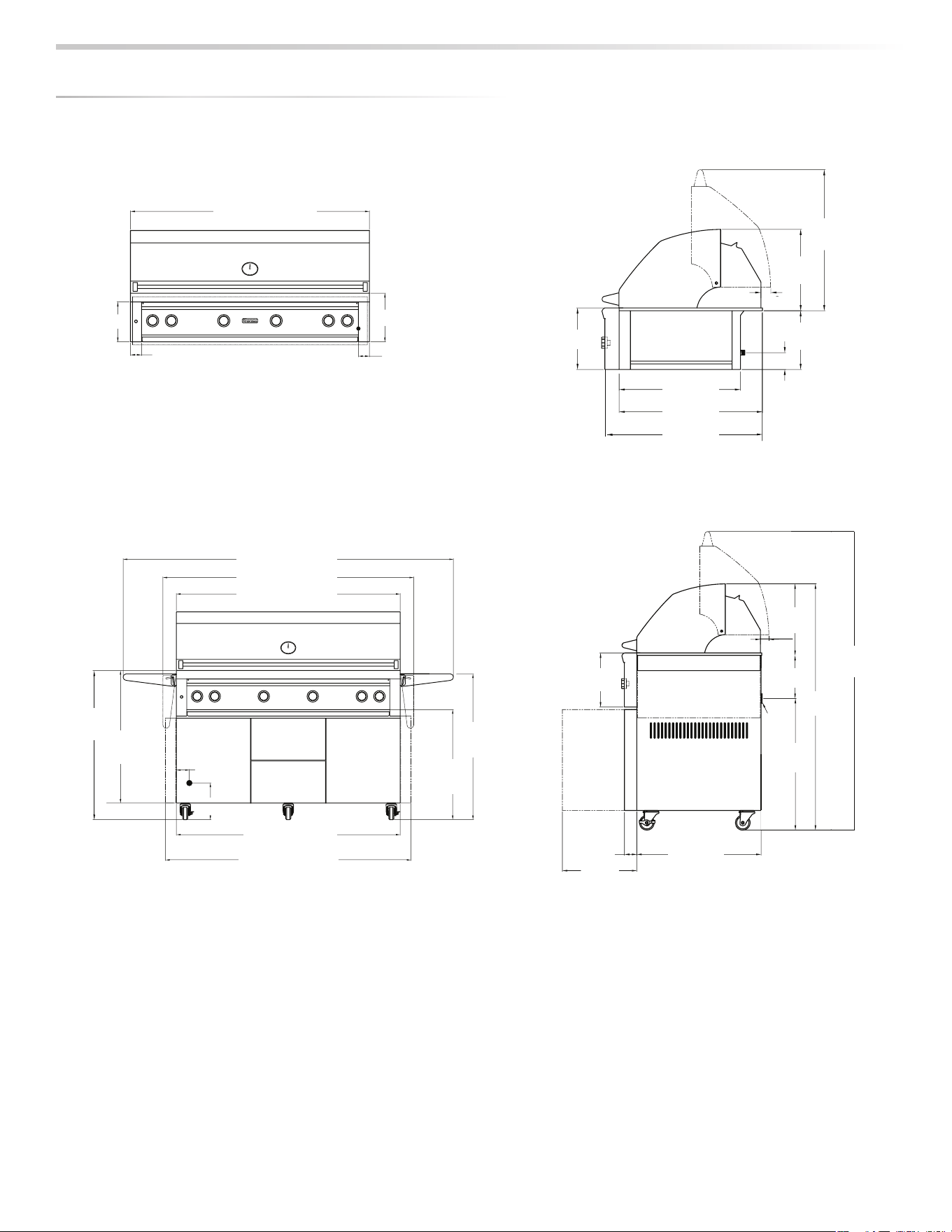
The guides, measurements and dimensions detailed below are designated to assist you with planning your outdoor kitchen.
NOTE: Due to continuing product innovation, specifi cations are subject to change without notice.
IMPORTANT: Please reference the Care & Use / Installation manual for details on gas plumbing requirements, electrical specifi cations and the
proper installation of your outdoor kitchen equipment. This manual can be downloaded from our website at www.vikingrange.com.
GRILLS
MODEL
ABC
L27 26.00 10.88 22.00
L30 29.00 10.88 24.50
L36 35.00 10.13 22.00
L42 41.00 10.88 24.50
L54 53.00 10.88 24.50
COMPLEMENTARY PRODUCTS
ACCESS DOORS
MODEL
A B
LSR18L/R-4 13.38 19.00
LSR24L/R-4 19.25 19.00
LDR30T-4 25.13 19.00
LDR36T-4 31.50 19.00
LDR42T-4 37.50 19.00
SIDE BURNERS
MODEL
A B C
LSB1-3 12.13 10.63 12.50
LSB2-2 12.13 10.63 24.50
LSB2PC-1 24.25 10.63 24.50
LPB 19.00 10.63 22.00
UTILITY DRAWERS
MODEL
A B C
LDW16-4 12.25 19.00 24.50
LDW19-4 15.25 19.00 24.50
LMD-4 21.75 5.63 23.38
LTWL 14.63 7.25 7.00
COCKTAIL PRO/SINK
MODEL
A B C
LCS30 29.00 10.50 22.00
LSK18 17.00 10.50 22.00
LSK24 23.00 10.50 22.00
LSK30 29.00 10.50 22.00
WARMING DRAWERS
MODEL
AB C
L30WD-1 28.50 10.00 20.50
L42CC-1 40.25 19.38 24.50
WITH INSULATED JACKET INSTALLED
MODEL A B C
LIJ27 33.00 11.63 23.75
LIJ30 36.00 11.63 26.50
LIJ36 42.00 11.63 24.00
LIJ42 48.00 11.63 26.50
LIJ54 60.00 11.63 26.50
S
PE
C
IFI
C
ATI
O
N
S
&
IN
S
TALLATI
O
N
Installation into a combustible enclosure requires an
insu
l
ate
d
j
ac
k
et accessor
y
.
N
ot insta
ll
in
g
an insu
l
ate
d
j
ac
k
et
could result in a fi re, in
j
ur
y
or propert
y
dama
g
e. Insulated
j
ac
k
ets ma
y
b
e or
d
ere
d
at
py
or phone
888
-
8
45-4
6
41 press 1. Please have
g
rill model and
seria
l
avai
l
a
bl
e w
h
en or
d
erin
g.
STORAGE DRAWERS
MODEL
A B C
LSA30-4 25.44 19.00 24.50
LSA36-4 31.44 19.00 24.50
LPA36-4 31.50 19.00 25.00
TRASH CENTER
MODEL
A B C
L20TR-4 16.13 24.00 24.50
LTA30-4 25.44 19.00 24.50
PIZZA OVEN
MODEL
A B C
LPZA 29.00 4.00 24.50
SMOKER
MODEL
A B C
LSMK 29.00 4.00 24.50
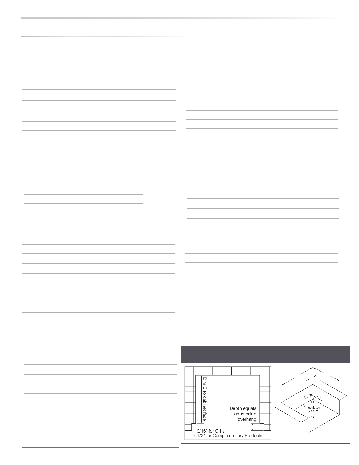
5”
(12.7 cm)
4.5”
(11.4 cm)
3”
(7.6 cm)
AA
B
C
COUNTER TOP NOTCH DETAIL
Only required if island counter top overhangs the face of the island
INSTALLATION / USE & CARE
|
9
B
A
3”
Min
OUTDOOR ICE AND REFRIGERATION
MODEL A B C D
LM15REFL/R 15.00 34.00 - 35.00 26.00 33.75 - 34.75
LM24REFL/R 24.00 34.00 - 35.00 26.00 33.75 - 34.75
LM24REFCL/CR 24.00 34.00 - 35.00 26.00 33.75 - 34.75
LM24BFL/R 24.00 34.00 - 35.00 26.00 33.75 - 34.75
LM24DWR 24.25 34.00 - 35.00 26.00 33.75 - 34.75
LMWINE 15.00 34.00 - 35.00 26.00 33.75 - 34.75
LM15ICE 15.00 34.00 - 35.00 24.00 33.75 - 34.75
S
PE
C
IFI
C
ATI
O
N
S
&
IN
S
TALLATI
O
N
L15ICE/LMWINE/LM15REF
L1
5I
CE
/L
MWIN
E/
LM
15
REF
L24REF/LM24BF/LM24DW
R
10
|
INSTALLATION / USE & CARE
MAXIMUM RUNS FOR ALL
APPLIANCES ON SUPPLY LINE
Run Length 3/4”
Pipe (in feet)
Max BTU for all
Appliances on line
10 360,000
20 245,000
30 198,000
40 169,000
50 150,000
60 135,000
70 123,000
80 115,000
MODEL-SPECIFIC BTU OUTPUTS & MAX. RUNS FOR APPLIANCES
MODEL-SPECIFIC BTU OUTPUTS
MODEL CERAMIC
BURNER (Btu)
ROTISSERIE (Btu) TRIDENT™ (Btu) TOTAL INPUT
L27R 2 @ 25,000 1 @ 14,000 64,000 Btu/Hr
L27TR(F) 1 @ 25,000 1 @ 14,000 1 @ 21,000 60,000 Btu/Hr
L30R(F) 2 @ 25,000 1 @ 14,000 64,000 Btu/Hr
L30TR(F) 1 @ 25,000 1 @ 14,000 1 @ 21,000 60,000 Btu/Hr
L36R 3 @ 25,000 1 @ 14,000 89,000 Btu/Hr
L36TR(F) 2 @ 25,000 1 @ 14,000 1 @ 21,000 85,000 Btu/Hr
L42R 3 @ 25,000 1 @ 16,000 91,000 Btu/Hr
L42TR(F) 2 @ 25,000 1 @ 16,000 1 @ 21,000 87,000 Btu/Hr
L54TR(F) 3 @ 25,000 2 @ 14,000 1 @ 21,000 124,000 Btu/Hr
S
PE
C
IFI
C
ATI
O
N
S
&
IN
S
TALLATI
O
N
INSTALLATION / USE & CARE
|
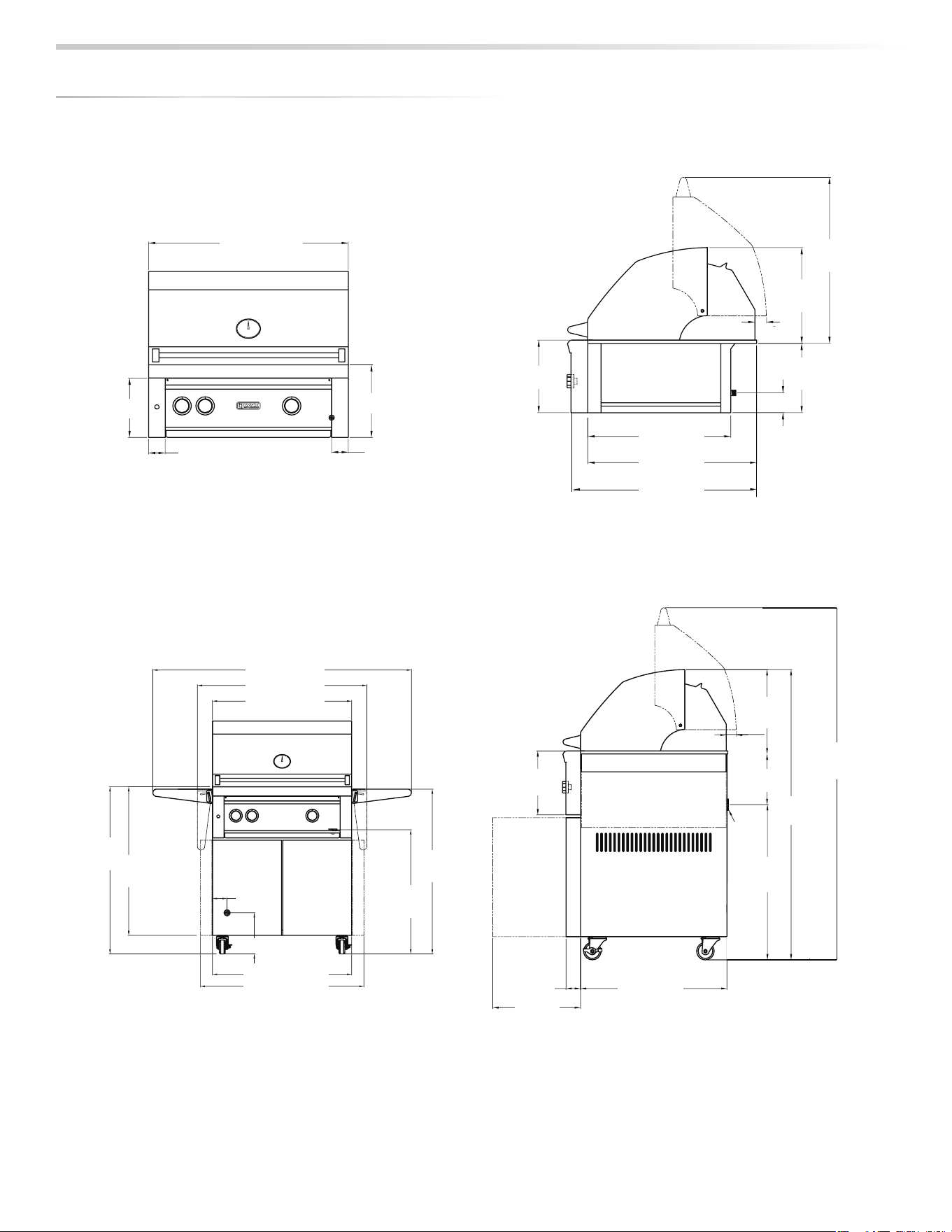
11
DIMEN
S
I
O
N
S
L
2
7
R
L
2
7T
R
L27TR
F
30"
11"
9"
REAR
MANIFOLD
LOCATION
2
1
/2"
2
1
/2"
25
3
/8"
27
7
/8"
1
3
/4"
21
1
/2"
10
1
/2"
14
1
/2"
25
3
/16"
11"
3"
30"
32"
36"
35
1
/2"
36
1
/2"
55
3
/4"
3
1
/8"
8
7
/8"
26
3
/4
30"
35
1
/4"
(DOORS OPEN AT 90°)
REAR CORD
LOCATION
11"
(DOORS OPEN AT 90°)
GAS
EXIT
50"
CORD
14
1
/2"
1
3
/4"
8
3
/4"
26
3
/4"
2
1
/2"
25
1
/4"
15
1
/8"
60
11
/16"
8
7
/8"
30”
(76.2 cm)
9” (22.9 cm)
11” (27.9 cm)
11” (27.9 cm)
1-
1/8” (2.9 cm)
2½” (6.4 cm)
233/16”
(64.0 cm)
14½”
(36.8 cm)
10½”
(26.7 cm)
3” (7.6 cm)
1¾”
(4.4 cm)
Rear Manifold
Location
19”
(48.3 cm)
227/8”
(58.1 cm)
253/8”
(64.5 cm)
27” (68.6 cm)
33½” (85.1 cm)
52¾” (134.0 cm)
32”
(81.3 cm)
35¼”
(89.5 cm)
34¾ ”
(95.6 cm)
26
1/16”
(61.2 cm)
27” (38.6 cm)
32¼” (81.9 cm)
31/8”
(7.9 cm)
87/8” (9.8 cm)
2½”
(6.4 cm)
135/8”
(34.6 cm)
22¾”
(57.8 cm)
26
1/16”
(66.2 cm)
49¼”
(125.1 cm)
5715/16”
(147.2 cm)
14½”
(36.8 cm)
8¾”
(22.2 cm)
1¾”
(4.4 cm)
11”
(27.9 cm)
12
|
INSTALLATION / USE & CARE
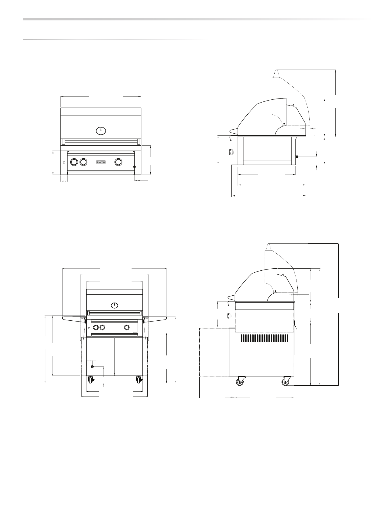
DIMENSI
O
NS
30"
11"
9"
REAR
MANIFOLD
LOCATION
2
1
/2"
2
1
/2"
25
3
/8"
27
7
/8"
1
3
/4"
21
1
/2"
10
1
/2"
14
1
/2"
25
3
/16"
11"
3"
30"
32"
36"
35
1
/2"
36
1
/2"
55
3
/4"
3
1
/8"
8
7
/8"
26
3
/4
30"
35
1
/4
"
REAR CORD
LOCATION
11"
GAS
EXIT
50"
CORD
14
1
/2"
1
3
/4"
8
3
/4"
26
3
/4"
2
1
/2
"
25
1
/4
"
60
11
/16"
8
7
/8"
30”
(76.2 cm)
9” (22.9 cm)
11” (27.9 cm)
11” (27.9 cm)
2½” (6.4 cm)
2½” (6.4 cm)
253/16”
(64.0 cm)
14½”
(36.8 cm)
10½”
(26.7 cm)
3” (7.6 cm)
1¾”
(4.4 cm)
Rear Manifold
Location
21½”
(54.6 cm)
253/8”
(26.7 cm)
277/8”
(70.8 cm)
30” (76.2 cm)
36½” (92.7 cm)
55¾” (141.6 cm)
32”
(81.3 cm)
36”
(91.4 cm)
35½”
(90.2 cm)
26¾”
(67.9 cm)
30” (76.2 cm)
35¼
”
(89.5 cm)
31/8”
(7.9 cm)
87/8” (9.8 cm)
2½”
(6 4 cm)
25¼”
(64 1 )
26¾”
(67.9 cm)
50”
(127.0 cm)
6011/16”
(154.1 cm)
14½”
(36.8 cm)
8¾”
(22.2 cm)
1¾”
(4.4 cm)
11”
(27.9 cm)
L
30R
L
30
T
R
L
30
TRF
INSTALLATION / USE & CARE
|
13
DIMEN
S
I
O
N
S
REAR CORD
LOCATION
GAS
EXIT
8
7
/16"
9” (22.9 cm)
11” (27.9 cm)
11/8” (2.9 cm)
2½” (6.4 cm)
Rear Manifold
Location
36” (91.4 cm)
11” (27.9 cm)
19”
(48.3 cm)
227/8”
(58.1 cm)
253/8”
(64.5 cm)
147/8”
(37.8 cm)
23½”
(59.7 cm)
97/8”
(25.1 cm)
3” (7.6 cm)
1¾”
(4.4 cm)
32”
(81.3 cm)
36”
(91.4 cm)
36” (91.4 cm)
42½” (91.4 cm)
61¾” (108.0 cm)
35½”
(90.2 cm)
26¾”
(67.9 cm)
26¾”
(67.9 cm)
50”
(127.0 cm)
5811/16”
(149.1 cm)
11” (27.9 cm)
1¾”
(4.4 cm)
31/8”
(7.9 cm)
87/8” (9.8 cm)
147/8”
(37.8 cm)
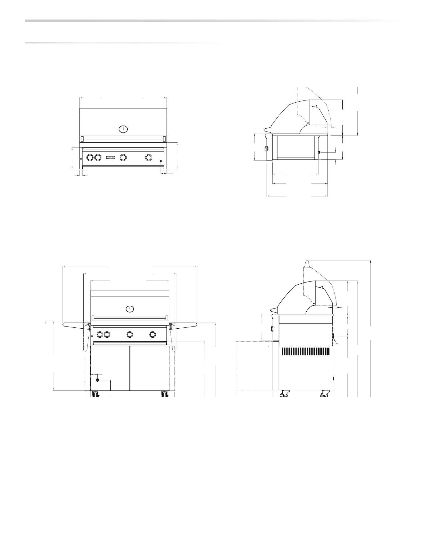
L
36R
L
36
TR
F
L
36
TRF
14
|
INSTALLATION / USE & CARE
DIMEN
S
I
O
N
S
REAR CORD
LOCATION
3
/8"
7
1
3
/4"
10
1
/2"
14
1
/2"
25
3
/16"
11"
3"
11” (27.9 cm)
253/16”
(64.0 cm)
14½”
(36.8 cm)
10½”
(26.7 cm)
3” (7.6 cm)
1¾”
(4.4 cm)
21½”
(54.6 cm)
253/8”
(64.5 cm)
277/8”
(70.8 cm)
11"
GAS
EXIT
50"
CORD
14
1
/2"
1
3
/4"
8
3
/4"
26
3
/4"
2
1
/2"
25
1
/4"
15
1
/8
"
60
11
/16"
8
7
/8"
2½”
(6.4 cm)
21
1
/8
”
25¼”
(64.1 cm)
26¾”
(67.9 cm)
50”
(127.0 cm)
6011/16”
(154.1 cm)
14½”
(36.8 cm)
8¾”
(22.2 cm)
1¾”
(4.4 cm)
11”
(27.9 cm)
32"
36"
32”
(81.3 cm)
36”
(91.4 cm)
30"
36
1
/2"
55
3
/4"
42” (106.7 cm)
48½” (123.2 cm)
67¾” (172.1 cm)
35½”
(90.2 cm)
26¾”
(67.9 cm)
13/16”
(3.0 cm)
63/16”
(15.7 cm)
42” (106.7 cm)
445/ ” (113 3cm)
9” (22.9 cm)
11” (27.9 cm)
2½” (6.4 cm)
2½” (6.4 cm)
Rear Manifold
Location
42” (106.7 cm)
L42T
R
L42TR
F
INSTALLATION / USE & CARE
|
15
DIMEN
S
I
O
N
S
(
DOORS OPEN AT 90°
)
GAS EXIT
REAR
3
/8"
7
1
3
/4"
10
1
/2"
14
1
/2"
25
3
/16"
11"
3"
11” (27.9 cm)
25½”
(64.8 cm)
103/16”
(25.9 cm)
3” (7.6 cm)
1¾”
(4.4 cm)
21½”
(54.6 cm)
253/8”
(26.7 cm)
277/8”
(70.8 cm)
11"
(
DOORS OPEN AT 90°
)
GAS
EXIT
50"
CORD
14
1
/2"
1
3
/4"
8
3
/4"
26
3
/4"
2
1
/2"
25
1
/4"
15
1
/8"
60
11
/16"
8
7
/8"
2½”
(6.4 cm)
181/8”
(46.0 cm)
25¼”
(64.1 cm)
50”
(127.0 cm)
6011/16”
(154.1 cm)
1413/16”
(37.6 cm)
85/8”
(21.9 cm)
1¾”
(4.4 cm)
11”
(27.9 cm)
9” (22.9 cm)
2½” (6.4 cm) 2½” (6.4 cm)
Rear Manifold
Location
54” (137.2 cm)
11” (27.9 cm)
54” (137.2 cm)
60½” (153.7 cm)
79¾” (202.6 cm)
REAR CORD
LOCATION
32”
(81.3 cm)
36”
(91.4 cm)
54” (137.2 cm)
59¼” (150.5 cm)
LOCATION
31/8”
(7.9 cm)
87/8” (9.8 cm)
353/16”
(89.4 cm)
269/16”
(67.5 cm)
269/16”
(67.5 cm)
1413/16”
(37.6 cm)
L54TR
L54TR
F
16
|
INSTALLATION / USE & CARE
The grill arrives nearly ready to use and requires only minor
assembly.
By carefully following the uncrating and unpacking steps,
you will improve your fi rst experience with the grill.
Shipping weight on smaller units is app. 300 pounds and
larger units may weigh over 500 pounds.
CRATE & CARTON
• IMPORTANT! Do not remove staples around the top of the
carton. These staples hold a wooden pallet in place inside
the carton that protects the unit from damage. Removing
these staples may cause the pallet to fall on the top of grill.
How to Remove the Carton
• Cut the main strap holding the grill to the pallet.
• Remove the staples at the bottom of the carton.
• Lift o the carton.
• With assistance, remove the grill from the pallet and place
into desired location.
The wheels sit down in the gaps of the shipping crate so
that the grill can sit safely and solidly on the crate during
shipping. The grill cannot be slid directly o of the pallet.
One way to safely move
the grill o of the pallet is
by lifting one end of the
grill high enough to place
a ramp under the wheel
and then lift the other end
while rolling the grill o of
the pallet.
When pushing, lifting, or pulling a freestanding grill across
gravel, grass, pavers, brick, stone imprefections in the
surface, or wood slatted decks be cautious and move slowly
or use a carpet dolly.
Failure to do so may damage the structure of the cart
wyhich will not be covered under warranty.
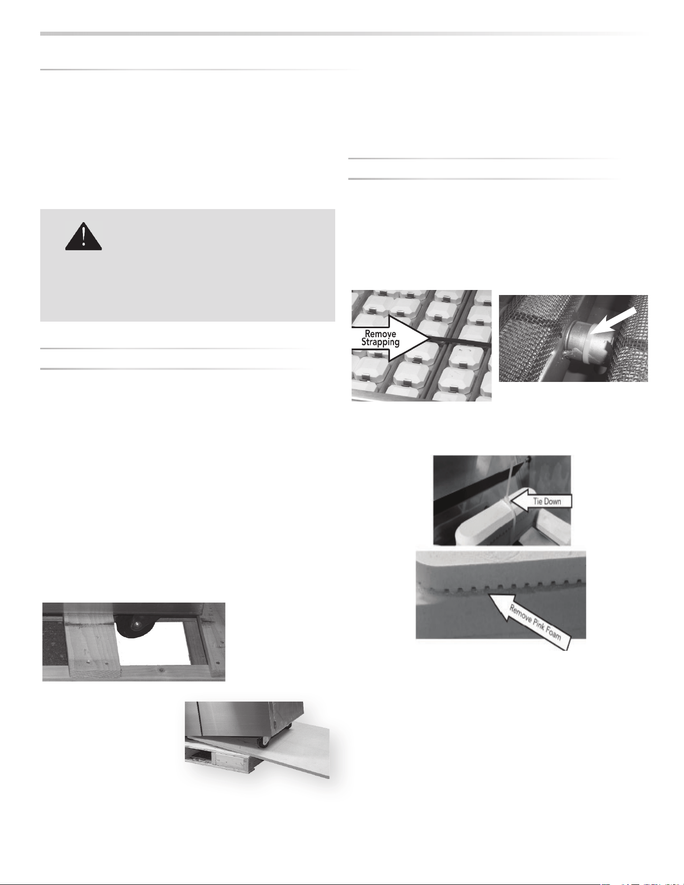
INTERIOR PACKING
Lynx uses sturdy tie-down cables and straps to ensure your
grill arrives at your home in the same condition that it left our
factory. BE SURE YOU HAVE REMOVED ALL TIE DOWNS
BEFORE USING YOUR GRILL.
• Remove the white accessory box and wood packing, the
grill racks, and remove any loose items from the fi rebox.
• Carefully cut the cable ties securing the warming rack and
rotisserie spit (if equipped).
• Cut the strapping that secures the briquette trays and
carefully lift them out, front fi rst.
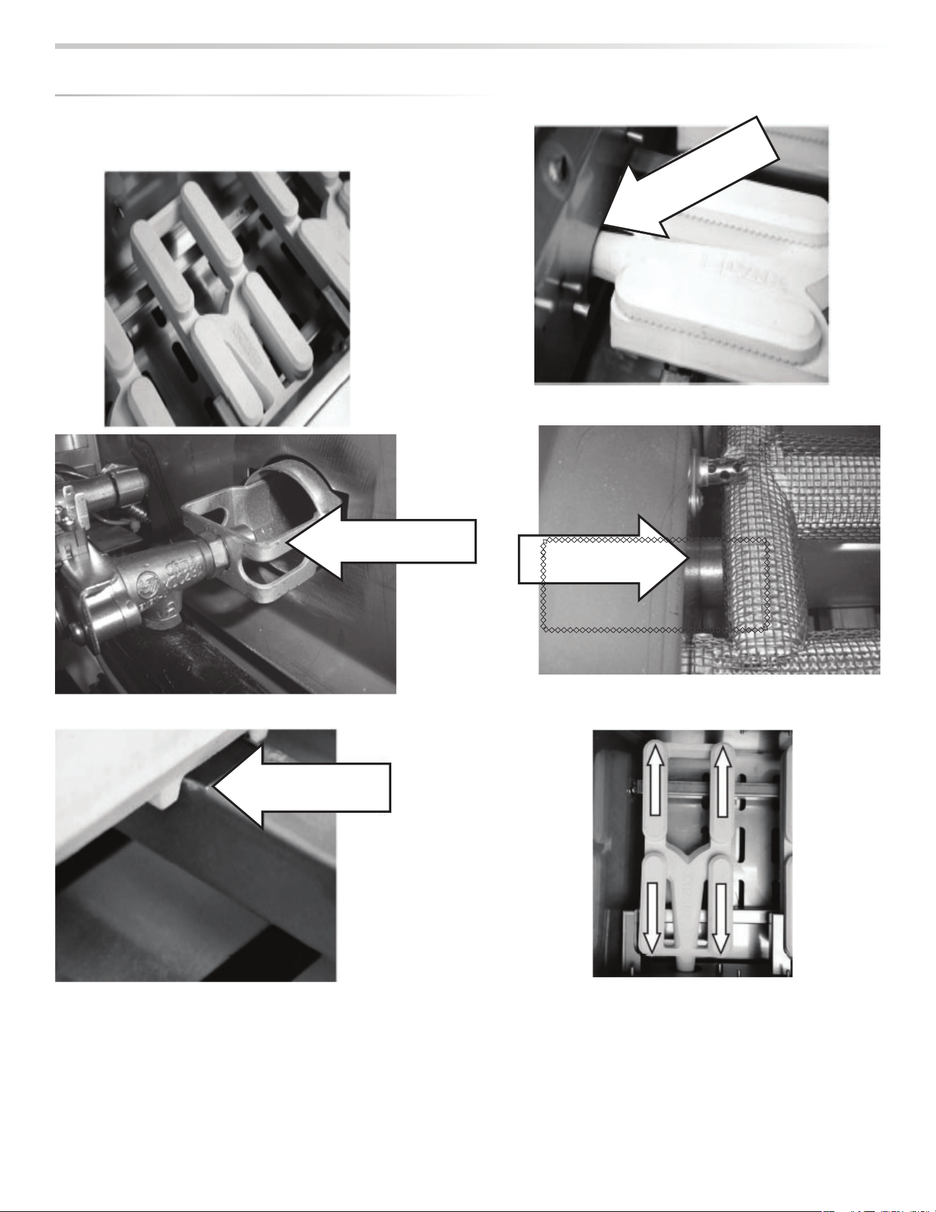
Make sure you remember to remove the tie-downs on the
burners.
• On Trident™ models, cut and remove ties from the burner
partition on the left side of the Trident™ burner.
• Ensure that all burners are properly seated on the burner
valve orifi ce and sitting level with the legs in the frame
slots and no side-to-side movement.
UNPACKIN
G
& ASSEMBLY
Use two or more people to move or install this unit.
Failure to follow this instruction can result in back
or other personal injuries.
WARNING:
EXCESSIVE WEIGHT HAZARD!
M
bu
•
•
INSTALLATION / USE & CARE
|
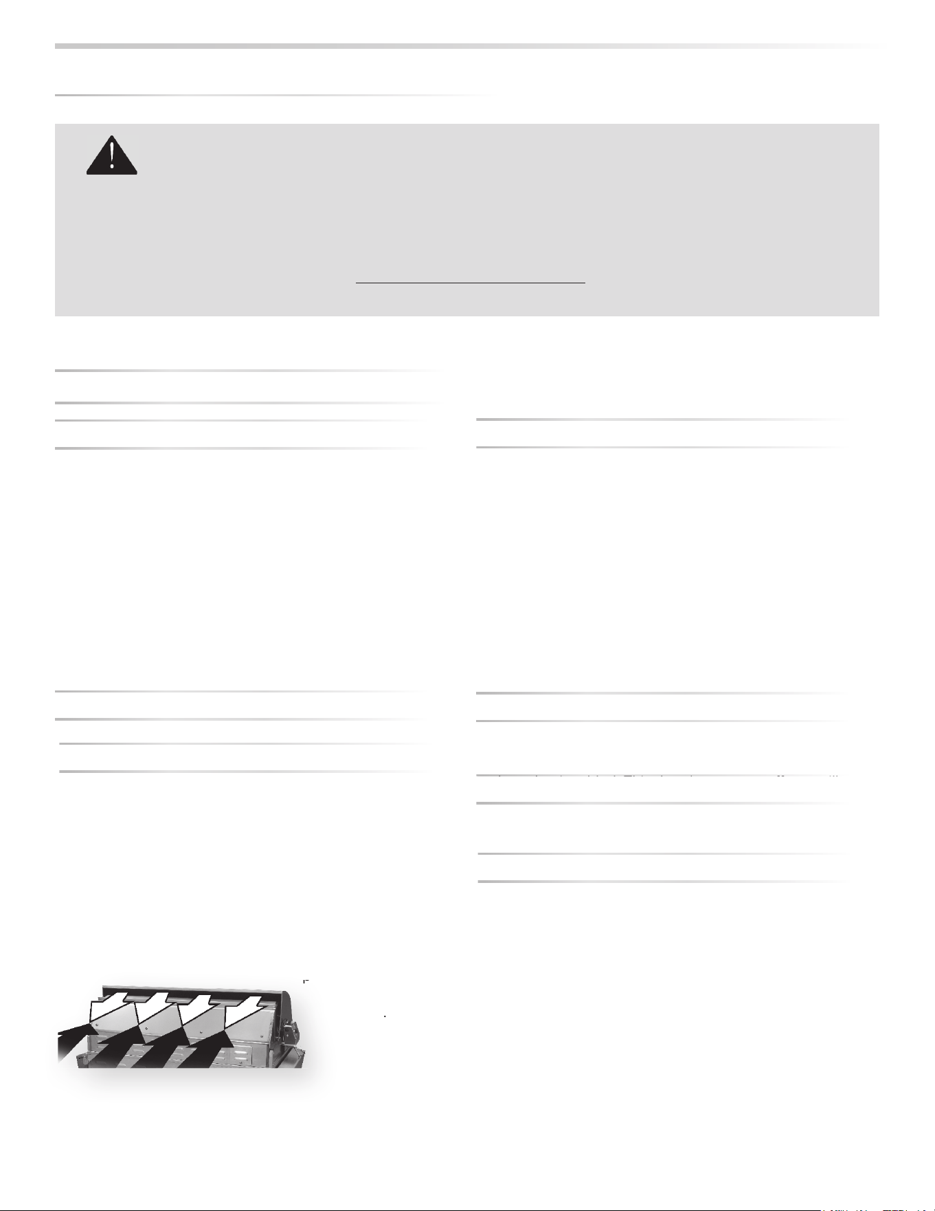
17
Inside View, Orifi ce
all the way into
venturi
UNPA
C
KIN
G
& ASSEMBLY
...
c
o
n
t
in
u
e
d
Burner Sitting Flat
Orifi ce all the way
into the venturi
Move the rear caps towards
the back and pull the front caps
forward
Heat Shield Removed,
Orifi ce/Venturi Position
s
s
s
t
t
t
en
e
n
en
18
|
INSTALLATION / USE & CARE
WARNING
NEVER CONNECT A GAS LINE DIRECTLY TO THE GRILL. A PRESSURE REGULATOR MUST BE INSTALLED ON ALL
GAS EQUIPMENT. ALL LOCAL CODES REQUIRE THAT THE PRESSURE REGULATOR SUPPLIED WITH YOUR GRILL
IS USED. REMOVIN
G
OR FAILIN
G
TO INSTALL THE PRESSURE RE
G
ULATOR CAN RESULT IN FIRE AND SERIOUS
PERSONAL INJURY AND WILL VOID THE WARRANTY.
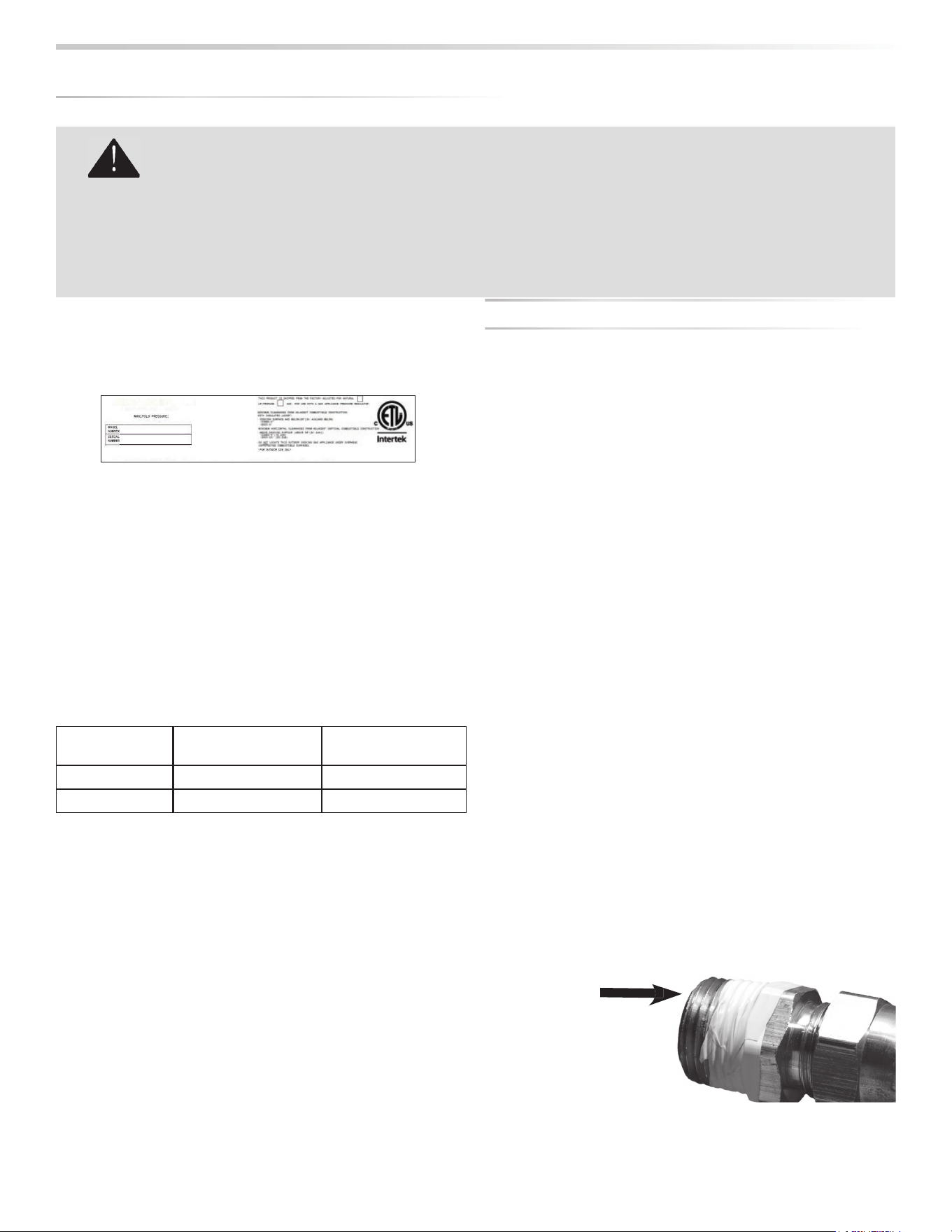
The grill is factory set to use either propane (LP) or natural
gas (NAT). It is critical that the gas you use matches that
which the grill was set up for. You can verify that by checking
the rating plate.
The Rating plate lists serial numbers, model numbers and gas type.
This one is underneath the drip tray.
The rating plate is located in one or more of the following
places:
• Attached to the underside of the drip tray
• On the heat shield behind the front panel
Ensure that the gas supplied meets with the minimum
pressure requirements. Do not operate the grill on any gas
other than that for which the grill has been set.
Fuel WC Max Inlet WC Min Under
Full Load
Nat Gas 7 in 4 in
LP 14 in 11 in
Water Column Requirements
Both the regulator and the manifold orifi ces have been tuned
for the type of gas specifi ed on the rating plate.
Converting to a di erent type of gas requires a conversion
kit, available from your dealer and must be installed by a
qualifi ed technician.
Installation must conform with local codes or, in the absence
of local codes, with either the National Fuel Gas Code,
ANSI Z223.1/NFPA 54, Natural Gas and propane Installation
Code, CSA B149.1, or Propane Storage and Handling Code,
B149.2, in Canada.Canadian installations must conform
to CGA-B149.1/.2 natural gas/propane installation code.
(Canada)
NATURAL GAS
Lynx, LLC recommends that only qualifi ed professionals
perform the required plumbing on this product.
To ensure satisfactory performance, the gas supply line must
be sized to accommodate the total BTU requirements of all
the gas-fi red equipment that will be connected to that line.
In no case should pipe less than 3/4” inside diameter or 1”
outside diameter ever be used to connect this product.
• Calculate the total BTU output of all equipment and
refer to “INDEX: Gas Supply Line Runs” for allowable run
distances for ¾ inch pipe. Failure to meet these minimum
requirements may reduce performance of the grill and any
other appliances running on that supply line.
• Always keep supply line runs as short as possible. (See
INDEX: “BTU Output” for specifi c model outputs)
• A gas shut-o valve must be installed in an easily
accessible location by a qualifi ed plumber.
• Keep threading compound o of the fi rst two pipe threads
to avoid having any small pieces of compound break loose
and clog a burner valve or orifi ce. Do not use threading
compound on any fl are fi ttings.
For built-in installations, it is recommended that any fl exible
pipe used be kept as short as possible. (See INDEX: “Gas
Connections” for typical permanent hook up.)
G
AS CONNECTION
S
K
eep
l
ast two
th
rea
d
s c
l
ea
n
LYNX GRILLS, LLC
Greenwood, Mississippi 38930
THIS DESIGN CERTIFIED UNDER ANSI Z21.58; CSA 1.6 OUTDOOR COOKING GAS APPLIANCE
NAT. 4” (996 Pa) LP/PROP 10” WCP (2492 Pa)
INSTALLATION / USE & CARE
|
19
For
freestanding
units using natural gas, using a metal fl ex hose
g
is recommended.
T
his is available at your local hardware store or from your
dealer.
LP GA
S
Grills set up for LP gas come equipped with an LP hose
/
regulator assembly for connection to a standard 20 lb. LP
cylinder. (Type 1). All fi ttings necessary to attach the assembly
t
o the grill are included.
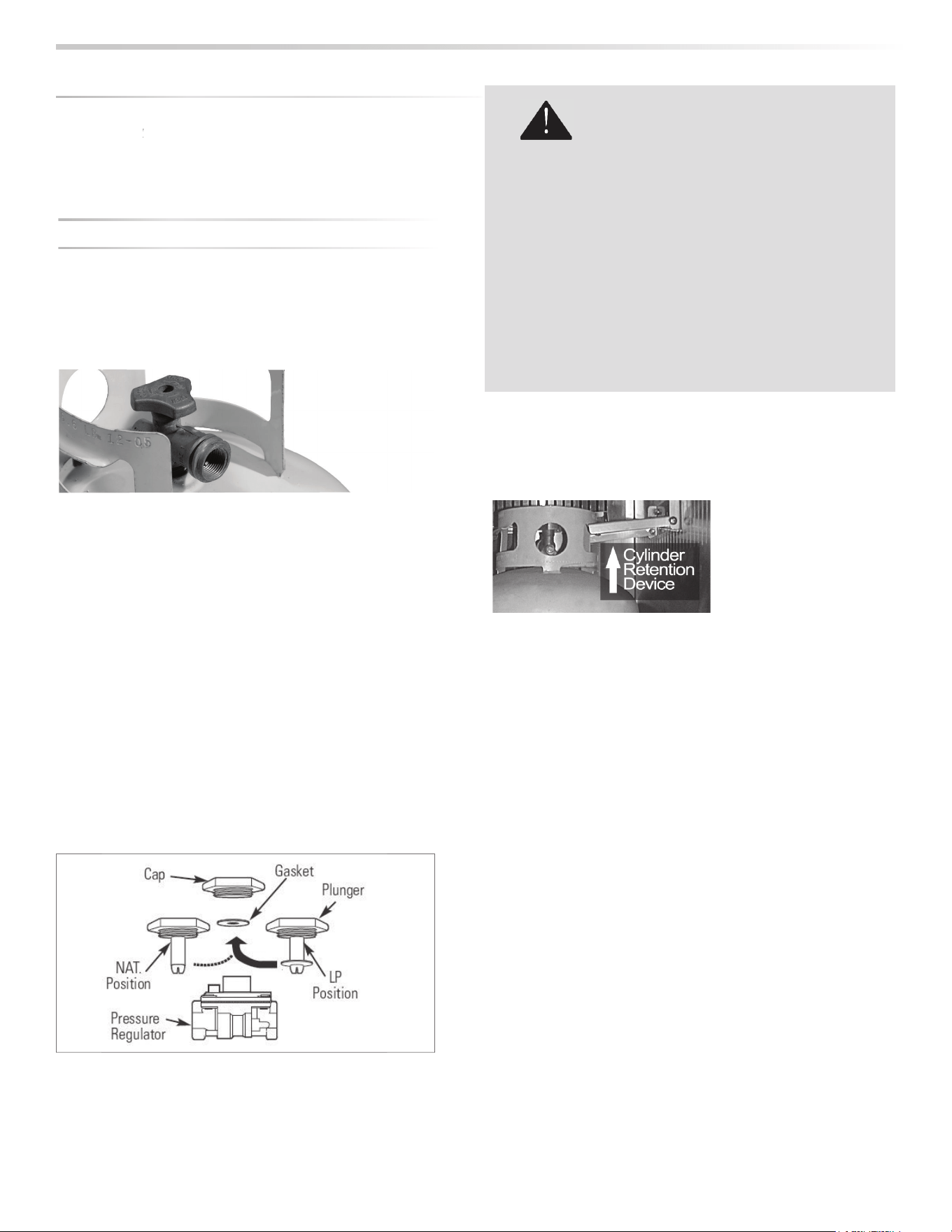
Permanentl
y
plumbed LP connections, such as those in line
with a bulk c
y
linder, require a 4/11 re
g
ulator.
When using the 4/11 regulator you must ensure that it is
s
et
f
or the proper
f
uel type. This is done by removing
th
e regu
l
ator cap an
d
gas
k
et an
d
l
oo
k
ing at t
h
e
b
ottom
of the plunger to see what fuel type is visible. This is the
regulator
f
uel setting. NAT is
f
or natural gas and LP is
f
or
propane gas. The LP setting can be
f
urther identi
fi
ed by the
large diameter disk on the bottom of the plunger. To change
f
rom one gas to the other simply push the plunger to the
s
ide to snap it out o
f
the cap, turn the plunger so it reads the
desired gas type on the bottom, and push the plunger until
it snaps
b
ac
k
into p
l
ace in t
h
e cap t
h
en rep
l
ace t
h
e cap into
th
e regu
l
ator.
Never connect an unregulated gas line to the grill.
L
P C
y
linder Requirements
Th
e
LP
cy
l
in
d
er must
b
e
c
onstructe
d
an
d
mar
k
e
d
i
n accor
d
ance wit
h
t
h
e
speci
fi
cations
f
or LP gas
c
ylinders o
f
the U.
S
. De-
partment of Transporta-
tion
(
DOT
)
and designed
f
or use with a Type 1 system only.
Cy
linders of free standin
g
g
rills must be secured usin
g
the
provi
d
e
d
c
yl
in
d
er retention s
y
stem to avoi
d
acci
d
enta
l
move
-
ment
.
W
hen exchanging your cylinder for a refi ll, exchange only for
a Type 1
20
lb cylinder with an over-
fi
ll protection device.
Never use a cylinder with a damaged valve.
A dented or rusty LP cylinder may be hazardous and should
be avoided. I
f
in doubt, have it checked by your LP supplier.
Always check for leaks after every LP cylinder change. (See
INDEX: “Leak Test” for further details.
)
Alwa
y
s shut o the LP-
g
as suppl
y
at the c
y
linder when the
g
rill is not in use.
C
ylinders must be stored outdoors in a well-ventilated area
o
ut o
f
the reach o
f
children. I
f
your grill is stored indoors, the
LP
cy
l
in
d
er must
b
e store
d
outsi
d
e
.
L
P
C
onnection
s
Make sure the LP cylinder valve is
f
ully closed. It is possible
f
or the valve to be open without releasing gas but, as soon
as you start connecting the regulator, gas will leak
f
rom the
c
onnect
i
on
.
LP cylinder with type 1 valve connection
G
AS
CO
NNE
C
TI
O
NS
...
co
n
t
in
u
e
d
Do not change the regulator/hose assembly or use
any other assembly than the one supplied with
your grill.
Do not attempt to use a 5LP-A equipped regulator/
hose assembly with a standard 510 POL cylinder/
valve assembly.
Do not store a spare LP-gas cylinder under or near
this appliance.
Never fi ll the cylinder beyond 80 percent full.
If the information above is not followed exactly, a
fi re causing death or serious injury may occur.
WARNING
20
|
INSTALLATION / USE & CARE
G
AS CONNECTIONS
...
co
n
t
in
u
e
d
Insert the regulator inlet into the cylinder valve and turn the
black coupler clockwise until the coupler is hand tight. Do
not over-tighten this connection.
To disconnect the coupler, fi rst make sure the main cylinder
valve is turned o . Grasp the coupler and turn counter
clockwise. The inlet will then disengage.
Always leak-test the connection after refi lling or exchanging
LP cylinders. (See INDEX: “Leak Test” for further details.)
GAS LINE PURGING
You should purge the gas line of air before attempting to
light the grill.
• Make sure all grill controls are in the “OFF” position.
• Slowly turn on the main gas supply.
• Push in the rotisserie knob and confi rm that the igniter
is glowing. It is furthest from the fuel source and will
completely purge the lines. It will take several seconds for
the burner to light.
• Hold the knob ON for about 20 seconds to allow the air in
the system to purge and the burner to light
• Wait at least 5 minutes after shutting o the control before
attempting to light the burners.
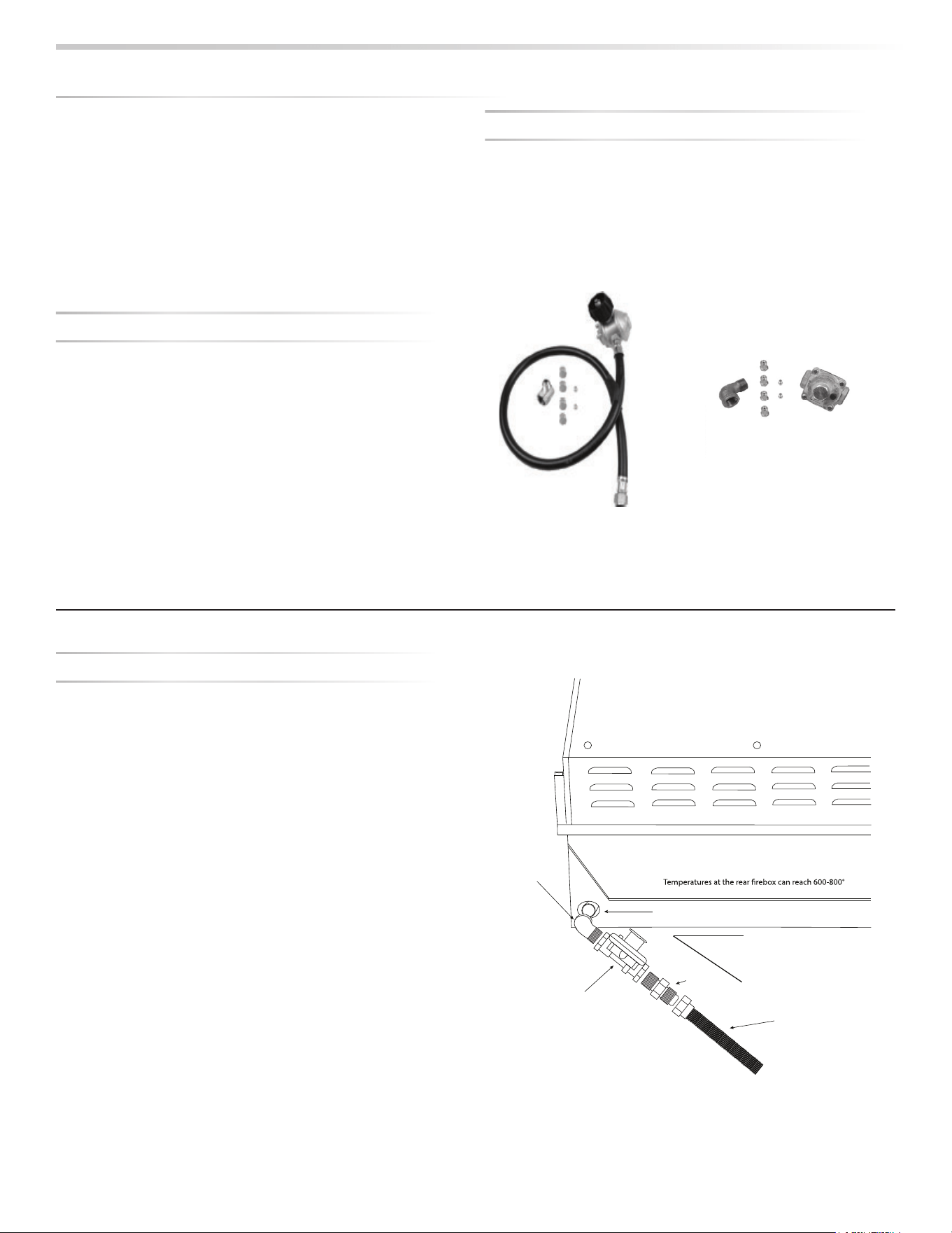
GAS CONVERSION KITS
Gas conversion kits are available from Lynx Grills to allow
the grill to operate on either Natural gas or LPG. These kits
should be installed by a qualifi ed technician.
The kits come with complete installation instructions. These
instructions should be read completely and fully understood
before installing the conversion kit.
LP CONVERSION KI
T
NG CONVERSION KI
T
N
G
AND BULK LP BUILT-IN INSTALLATION
•
S
hut o
the gas supply at the main valve
.
•
I
f
connecting to a bulk propane tank, disconnect the
b
rass elbow, hose and regulator
f
rom the grill.
•
Remove all
fi
ttings
f
rom the grill mani
f
old.
•
C
onnect the
g
as suppl
y
to the
g
rill as shown in the
d
ia
g
ram on t
h
is pa
g
e
.
•
Turn the gas supply on and leak test all connections.
(
See
INDEX:
“
Leak Test
”
f
or
f
urther details
.
Never run
fl
ex hose behind the
fi
rebox. Run the hose at an
a
ngle, straight down or out o
f
the bac
k
Inline Regulator
1/2” MxF
Street
Elbow
Angle At Least
20˚ From Horizon
Grill Manifold
1/2” MIP
Fitting
Flexible Gas Line to Inlet
INSTALLATION / USE & CARE
|
21
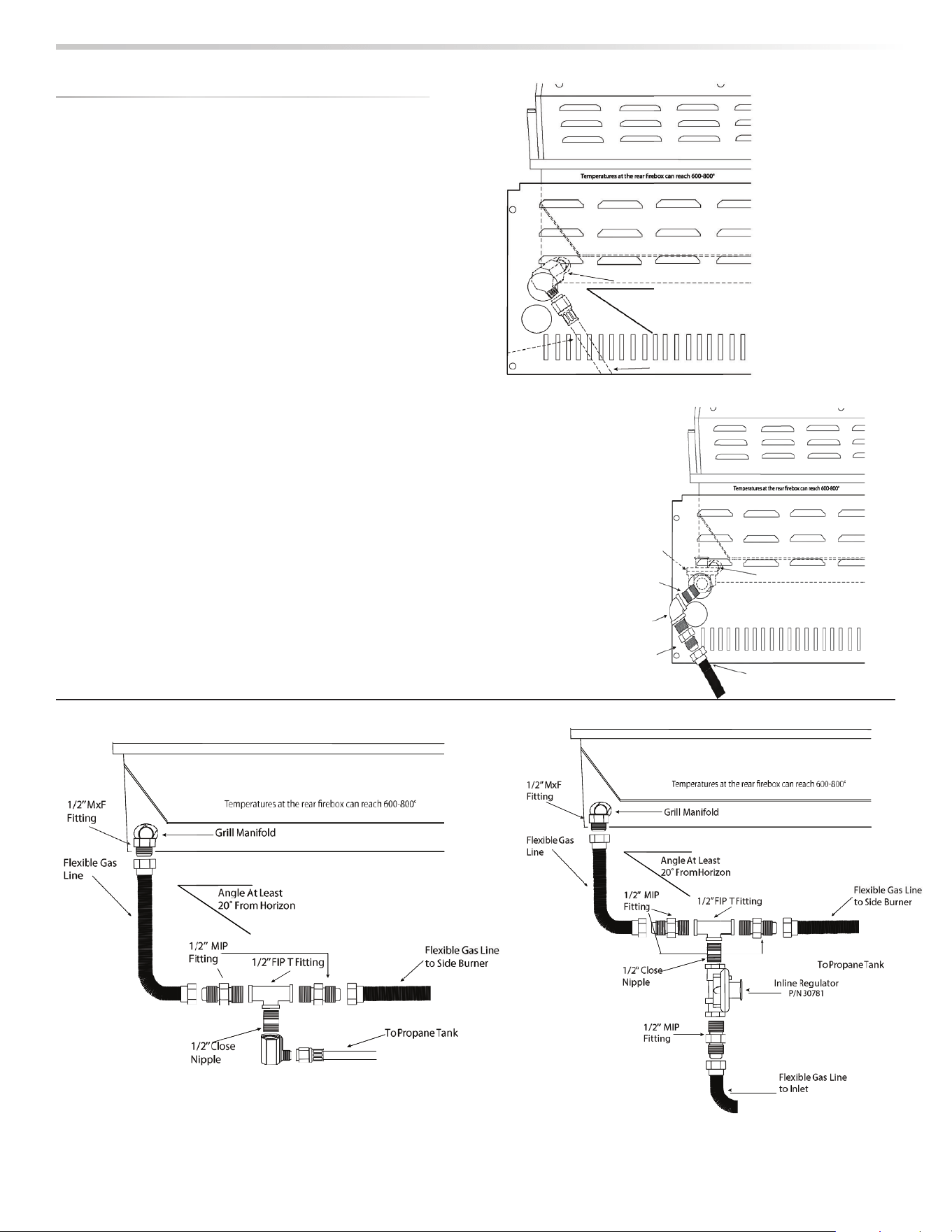
NG AND BULK PROPANE CART INSTALLATION
• Shut o the gas supply at the main valve.
• Disconnect all plumbing (if already attached) from the grill
and the gas supply valve.
• Remove all the fi ttings from the grill manifold.
• Install the side burner into the counter top cutout.
• Connect the gas supply to the grill as shown in the
diagrams on this page for your gas type.
• Turn the gas supply on and leak test all connections. (See
INDEX: “Leak Test” for further details.)
G
AS
CO
NNE
C
TI
O
NS
...
co
n
t
in
u
e
d
LP BOTTLE CART INSTALLATION
• Shut o the gas supply at the main valve.
• Connect the gas supply to the grill as shown in the diagram
on this page for your gas type.
• Turn the gas supply on and leak test all connections. (See
INDEX: “Leak Test” for further details.)
the
g
g
rill
e
n
s.
(S
S
ee
Grill Manifold with Brass Elbow
Angle At Least
20˚ From Horizon
Regulator
P/N 13053
To Propane Tank
Grill Manifold
Flexible Gas Line to Inlet
Inline
Regulator
1/2’’ Close
Nipple
1/2’’ FIP
Street
Elbow
1/2’’ MIP
Fitting
SIDE BURNER INSTALLATION

22
|
INSTALLATION / USE & CARE
Installation requires an outdoor 120VAC 15A GFI (Ground
Fault Interrupter) electrical outlet adjacent to the grill.
The GFI outlet features an internal breaker that reduces
shock hazard. This type of outlet should be installed by a
qualifi ed electrician either inside the island enclosure for
built-in units, or near the location where a free-standing unit
will be used.
For built-in grills, the supplied 12VDC should be installed
below the grill within the cabinet enclosure. Select a location
where the transformer is protected against water, heat and
physical damage.
When installing the transformer to the grill be careful to
prevent the wiring and transformer from contacting any
hot surfaces behind or below the grill. It is recommended
that the transformer be located below the grill in a readily
accessible location. Be sure to provide adequate access to
facilitate service if the transformer or connections should
need future maintenance.
If the electrical system fails to operate, a connection may
have come loose in shipping or the GFI may have tripped,
requiring a reset. See the Troubleshooting section for more
details.
CONNECTION TO AC
ELE
C
TRI
C
AL
CO
NNE
C
TI
O
N
S
• Product installation must meet local electric codes or, in the absence of local codes, the latest edition of the
National Electrical Code ANSI/NFPA No. 70 or the Canadian Electrical Code CGA 1.6b2005.
• Use only a Ground Fault Interrupter (GFI) protected circuit with this outdoor cooking gas appliance.
• IMPORTANT: When connecting your rotisserie motor, fi rst connect the motor to the grill and then plug the grill into
the outlet.
• This grill is equipped with a three prong (grounding) electric plug for your protection against shock hazard and
must be plugged directly into a properly grounded three prong outlet. Never cut or remove the grounding prong
from this plug.
• Use only extension cords with a 3 prong grounding plug, rated for the power of the equipment, and approved for
outdoor use with a “W-A” marking.
• To protect against electric shock, do not immerse any part of the power cord, an extension cord or any plugs in
water or other liquid.
• Unplug the product from the outlet when not in use and before cleaning. Allow it to cool before putting on or
taking o parts.
• Do not let the cord hang over the edge of a table or touch hot surfaces.
• Do not use an outdoor cooking gas appliance for purposes other than intended.
• Do not operate any outdoor cooking gas appliance with a damaged cord, plug, or after the appliance malfunctions
or has been damaged in any manner. Contact the manufacturer for repair.
WARNING: ELECTRICAL GROUNDING
INSTALLATION / USE & CARE
|
23
FINAL
C
HE
C
K
S
LEAK TESTING
Leak Test Procedure:
• Create a soapy solution of 1 part soap and 3 parts water.
• Confi rm that all control knobs are in the o position.
• Turn on the fuel supply. For natural gas, turn the valve
handle 1/4 turn to align with the gas fl ow.
• For L.P., turn the cylinder valve knob counter clockwise one
full rotation.
• Apply the soap solution generously by paint brush or squirt
bottle on all connections and fi ttings.
• If bubbles appear to “grow” on any of the connections, you
have a gas leak. IMMEDIATELY turn o the gas supply.
Fixing a Gas Leak:
• Shut o the gas supply
• Turn all grill controls to the “ON” position to purge the grill
of any gas build-up, then turn the controls back “OFF”.
• Wash o the soapy solution with cold water and dry.
• Tighten the loose joint, or replace the faulty part with
manufacturer-recommended replacement parts.
• DO NOT attempt to repair the L.P. cylinder valve if it is
damaged. The only way to safely resolve a damaged
cylinder is to REPLACE IT.
• Repeat the leak test to ensure that no leaks are present.
LOW HEAT BURNER ADJUSTMENT
FOR MAIN CERAMIC BURNERS AND TRIDENT™ BURNERS
ONLY!
DO NOT ADJUST THE ROTISSERIE BURNER.
The main ceramic burners and Trident™ burners on your grill
feature an adjustable low setting.
Fluctuations in gas pressure, gas conversion and even in the
quality of the gas itself may a ect burner performance at the
“LOW” setting. It could be either too high or too low.
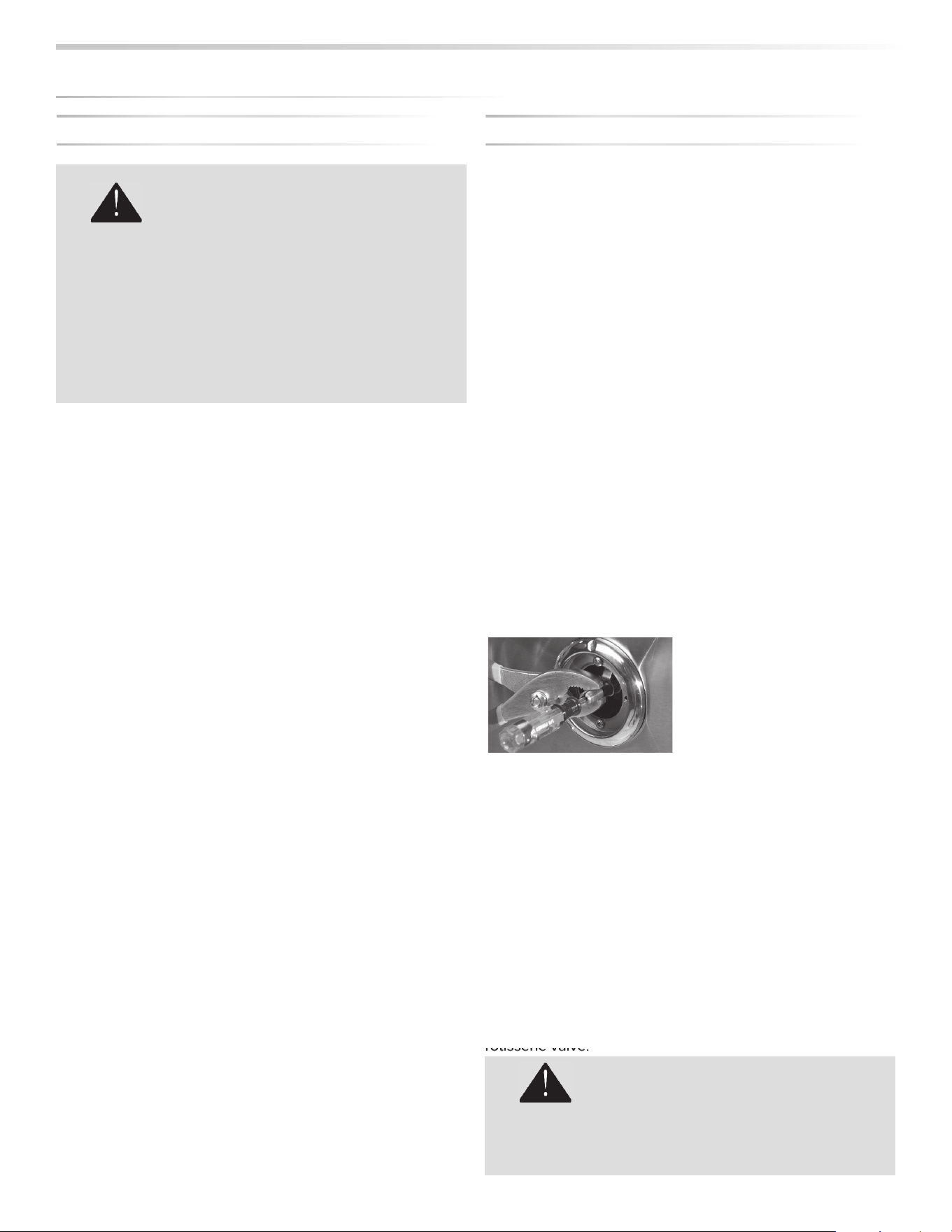
To Adjust the Burner to a Low Setting:
• Make sure the grill is cool.
• Remove the racks so you can see the fl ames while
adjusting the burners.
• Light the burner and allow it to preheat on high for 3
minutes.
• Turn the burner to “LOW”.
• Pull o the control knob.
• While holding the valve shaft with pliers as shown insert a
small fl at screwdriver into the center shaft and adjust the
fl ame’s low setting.
• Clockwise will lower the fl ame setting, counterclockwise will
raise it.
The proper setting is where the fl ame is stable at its lowest
setting. A slight fl utter will be present in the crossover portion
of the front of the burner before the burner itself becomes
weak.
The factory setting for propane gas is ½ to ¾ turn from the
very bottom of the adjustment. The setting for natural gas is
1-½ to 1-¾ from the bottom. After the low settings are proper,
turn all burners to high for visual inspection.
Please note the low fl ame adjustment is not available for the
rotisserie valve.
To prevent fi re or explosion hazard, DO NOT
smoke or allow any potential source of ignition
(sparks, electrical arcing, etc) in the area while
performing a leak test. Leak tests should be
conducted outdoors only. Never conduct a leak
test using fi re or fl ame.
DANGER!
ro
ro
ro
ro
o
ti
ti
ti
ti
t
ss
ss
ss
ss
ss
er
er
er
er
e
ie
ie
ie
ie
e
v
v
v
v
al
al
al
al
a
ve
ve
ve
ve
e
.
.
.
.
.
BE EXTREMELY CAREFUL AROUND HOT
BURNERS AND OTHER GRILL PARTS.
DANGER!
24
|
INSTALLATION / USE & CARE
FINAL
C
HE
C
K
S
...
c
o
n
t
in
u
e
d
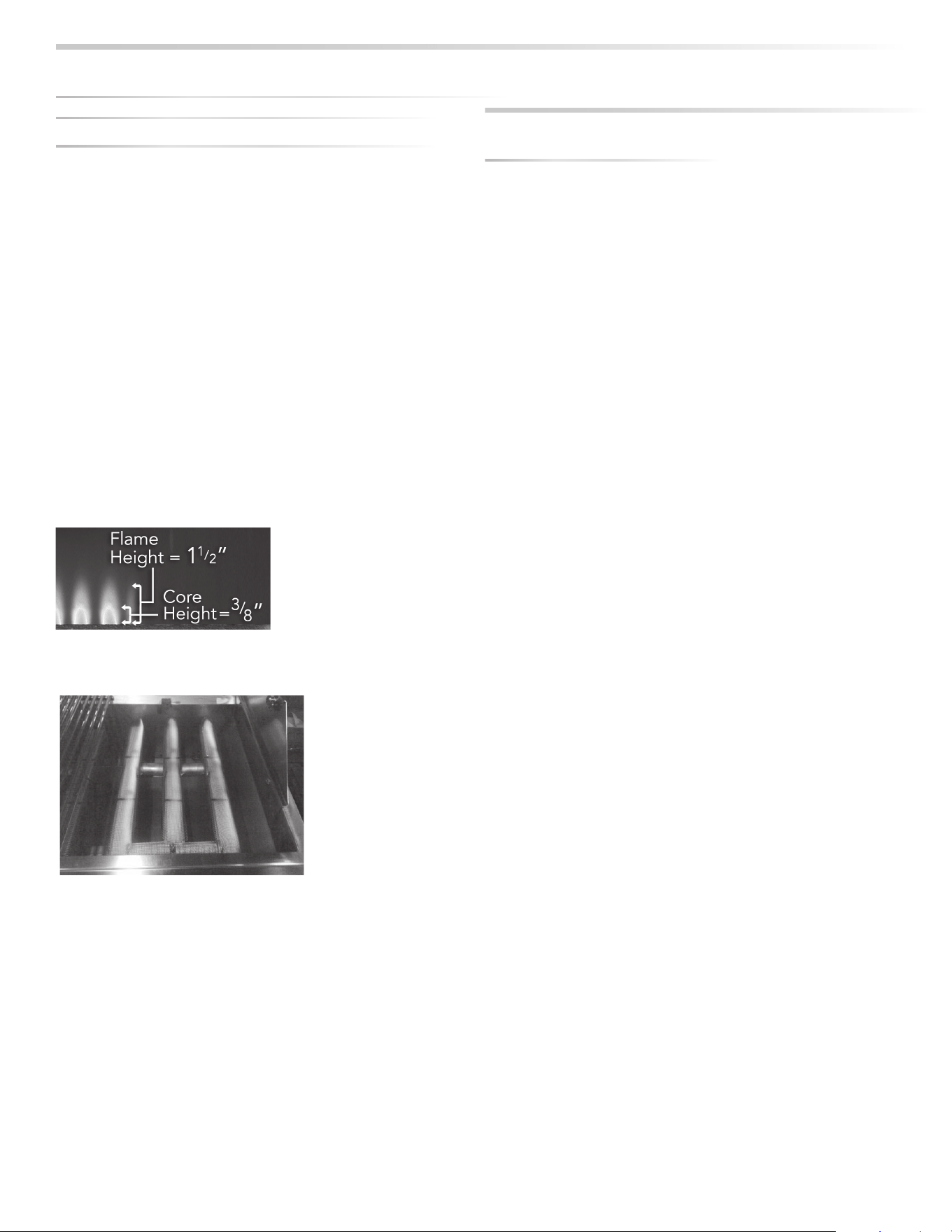
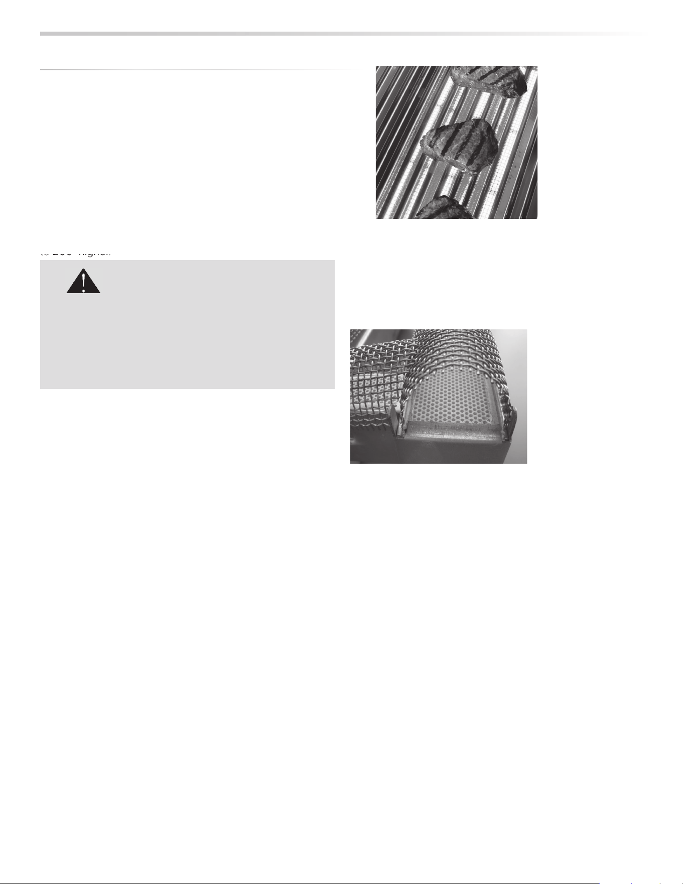
BURNER FLAME ADJUSTMENT
Each grill burner is tested and adjusted at the factory prior
to shipment. However, fl uctuations in gas pressure, gas
conversion and even in the quality of the gas itself may make
it necessary to adjust the burner.
Flames should be blue and stable with slight yellow tips. The
bright-blue core should be about 3/8 inch high with a total
fl ame height of about 1 1/2 inches.
The fl ames should burn quietly (no “torch” sounds) and they
should not “lift” up from the burner.
If your fl ames do not match those indicated in the photo,
ensure that burner ports are free and clear of dirt, debris, or
spider webs.
The appearance of the Trident™ burner should be visually
checked. The ceramic tiles should be uniformly red to
orange in appearance. There should be no lifting, fl uttering
or lazy blue fl ames. Some food particles will show as yellow
fl ames but should burn o .
ONE LAST THING
Finally, before leaving, check all the burners for proper
operation. Make sure the control knobs turn freely and
completely through their full range.
IMPORTANT:
Make sure the owner knows where the main gas supply shut
o valve is located.
Finally, for safety and for proper use & care, you must leave
this manual with the owner. Make sure you advise them to
keep it for future reference.
For technical assistance call:
Lynx Customer Care
888-289-5969
• Do you smell gas? If yes, shut o everything and call the
gas company or a qualifi ed plumber to check for leaks, if
not please continue.
• Are you prepared to stay with the grill during the entire
cooking process? If not, gather what you need before
starting the lighting process. If yes, please continue.
• Is your cooking area free and clear of any combustibles,
besides your food, that might ignite? If not, clear the area
before starting the lighting process, If yes, please continue.
• Do all control knobs turn freely? If not, call for service, if
yes, please continue.
• If you are using a portable propane cylinder, is it connected
and leak tested? If not, check the connection before
continuing. If yes, please continue.
• Do you know where your grill’s main gas supply shut o
valve is located? If not, locate it before continuing. If yes,
please continue.
• Are all burners properly seated in the grill with mounting
legs in slots? If not, seat the burners properly before
continuing. If yes, please continue.
• Is the wind blowing just lightly and not blowing on the back
of the grill? If not, wait until the wind subsides or turn your
free standing grill so the wind goes into the front of the grill.
If yes, please continue with the lighting process.
CHECKLIST BEFORE EACH USE
(FOR YOUR SAFETY)
INSTALLATION / USE & CARE
|
25
You’ve just joined a discriminating collection of amateur and professional chefs that
take outdoor cooking to a new level.
Your grill has been designed and built with meticulous attention to detail and it o ers
some unique and powerful features. You can achieve maximum performance and
enjoyment of these features only by carefully reading this manual ... before your fi rst
cook-out.
This manual includes important safety tips and great hints for better grilling. You’ll
want to keep it handy for easy reference.
Also, we enjoy hearing from our customers. We like to hear about your successes
but also about any di culties you are having. Please feel free to contact us with
any questions or problems, or just to share a new recipe. Please include the model
number of your grill in your correspondence.
With the proper use and care this product
will provide years of trouble-free service.
Should your grill change ownership, please
make sure that the new owner receives this
manual.
Thanks again for your purchase. Enjoy!
A MESSAGE TO OUR CUSTOMERS
1. NEVER LEAVE THE GRILL UNATTENDED WHILE
COOKING.
2. Ensure all tie-down wires have been removed from the
burners.
3. Always use caution when operating the grill in a windy
area. (See INDEX: “Grilling in Windy Conditions” for
further details.)
4. Avoid wearing loose-fi tting garments or long sleeves
while grilling. They could ignite.
5. Never touch the grill racks, hood or immediate
surrounding metal surfaces with your bare hands while
grilling.
6. Use an insulated glove or mitt when opening and
operating the grill. Always open the grill lid slowly to
allow heat and smoke to escape before fully opening.
7. The grill hood must be fully opened while lighting the
grill. Releasing fuel into a closed grill before lighting will
not make it light sooner or more e ciently. It will only
risk explosion and personal injury or death. Never lean
over a hot grill surface or look directly into the grill when
attempting to light.
8. Do not heat unopened food containers as pressure
build-up will cause the container to explode.
9. Do not use aluminum foil to line grill racks or drip pans.
This will alter the airfl ow or trap excessive heat in the
control area and can melt control knobs and ignition
modules. Such damage is specifi cally excluded from
your warranty.
10. Never use charcoal or any other solid fuel in the grill.
11. Cooking excessively fatty meats and oils will cause fl are
ups. Internal fi res or damage caused by them or by the
grill being left unattended while cooking are not covered
under the terms and conditions of our warranty.
12. Never grill without the drip pan in place. Always ensure
the drip pan is pushed all the way to the back of the grill.
Hot grease can leak downward and produce a fi re or
explosion.
13. Grease is extremely fl ammable. Let hot grease cool
down before attempting to handle or dispose of it. The
drip tray should be cleaned of grease on a regular basis.
14. Do not use the grill unless a leak check has been
performed on all gas connections. (See INDEX: “Leak
Test Procedure” for further details.)
15. Never operate the grill while under the infl uence of
alcohol or drugs.
16. Do not lean on side shelves and never place a load
weighing more than 25 pounds on a side shelf.
17. If any burner does not light or goes out during
operation, turn o all gas control knobs, open the hood
and wait fi ve (5) minutes before attempting to re-light.
18. Portable L.P. cylinders: Always shut o the main valve on
the L.P. cylinder after each use.
19. Spiders and insects like to nest in the burners, venturis,
valves and orifi ces of a grill, disrupting the gas fl ow. This
very dangerous condition can cause a fi re behind the
control panel, damaging the grill and risking personal
injury. If your grill has been unused for a long time,
inspect and clean the burners, venturis, valves and
orifi ces. (See INDEX: “Cleaning the Brass Burner” for
further details.)
PLEASE REVIEW THESE IMPORTANT SAFETY PRECAUTIONS BEFORE YOU USE YOUR GRILL
.
26
|
INSTALLATION / USE & CARE
Outdoor grills create more heat than interior kitchen ranges.
That’s how they sear and grill steaks and other foods.
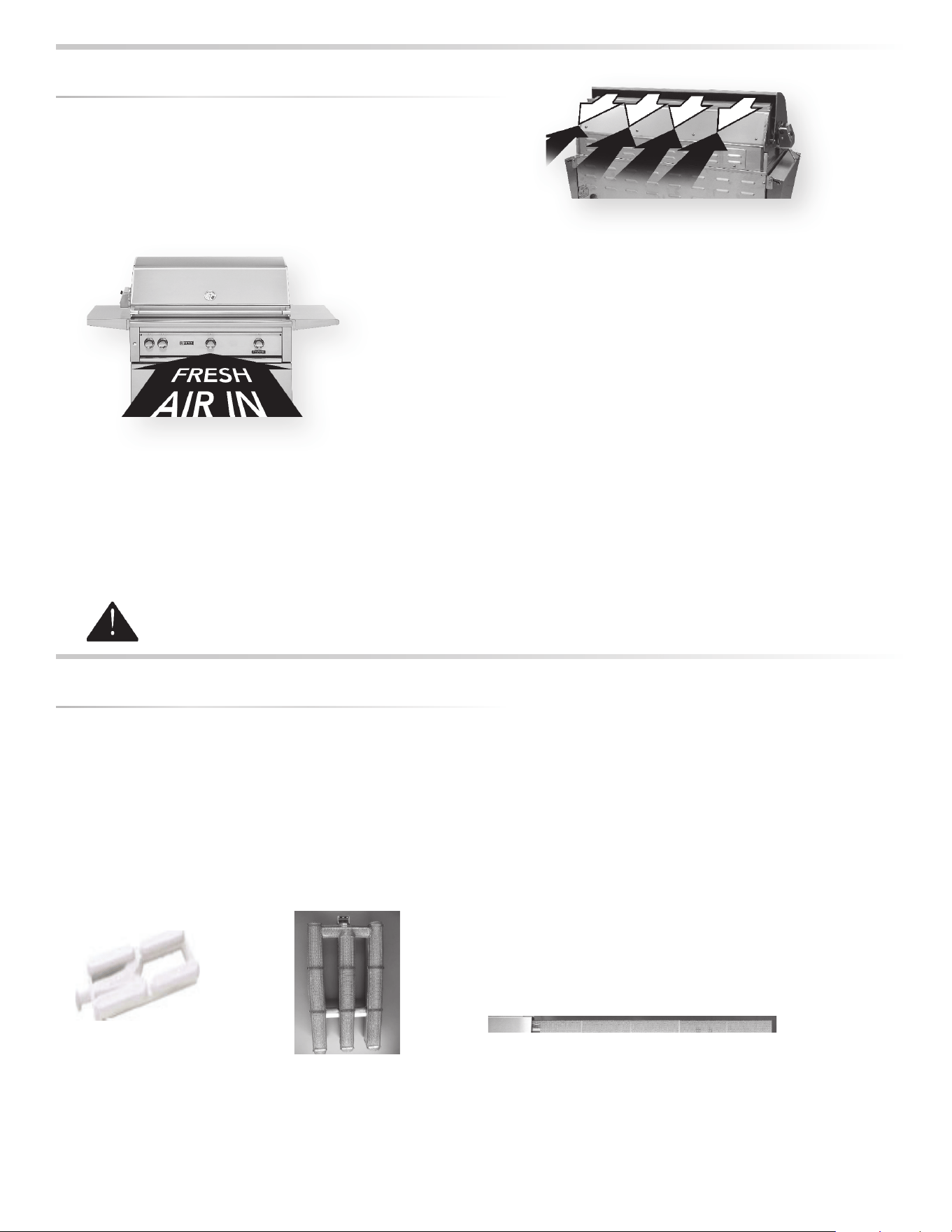
These high-performance burners require a constant, steady
supply of fresh air to mix with the fuel. Your grill pulls air in
through the front and vents hot gases out through the rear.
Using your grill in windy conditions may disrupt the front-
to-back air fl ow. If, while grilling with all burners on high and
the hood closed, you notice that the temperature gauge fails
to rise ... be careful. If wind has kept hot gases from exiting
the rear of the grill the control panel and knobs may have
become extremely hot.
Your grill features a heat stabilizer that will defl ect wind and,
in most cases, prevent this situation.
But there are a few things you can do to further prevent the
possibility of improper heat buildup:
• On breezy days, be careful not to leave the front
hood down for more than 15 minutes when the burners
are on high. (Never leave the grill unattended when in
operation)If you suspect the grill is overheating, using
an oven mitt, open the front hood. Then adjust the burner
control knob to a lower setting.
• Install your grill with a wind break behind it.
• Orient the grill so prevailing winds are not blowing into the
rear of the grill.
GRILLING IN WINDY CONDITIONS
Wind hitting the back of the grill can disrupt proper exhaust.
Air enters through the front of the grill.
Pl
ease
N
ot
e
: An
y
dama
g
e caused
f
rom use in wind
y
conditions, such as melted knobs or i
g
niter
wires, or control panel discoloration
f
rom heat buildup, is excluded
f
rom warrant
y
covera
g
e
.
USIN
G
Y
O
UR
G
RILL
Grilling requires high heat for searing and low, controlled
heat for slow cooking.
Thinner cuts of food are often cooked at a “HI” heat setting
with the lid open.
On the other hand, large, thick pieces of meat or poultry
are often fi rst seared at the high setting and then grilled at
a lower setting ... sometimes with the lid closed … achieving
the best results in the middle of the food without burning the
outside.
Some foods are cooked using direct heat and some using
indirect heat.
Your grill features a variety of professional-level burners and
tools for meeting the wide variety of cooking challenges. We
will reveal how these features work for you. So please read
and enjoy!
Depending on the model you chose, your grill may
be equipped with up to three di erent burner types.
The operation of each type varies, so it is important to
understand all three.
Main Ceramic Burner
This ceramic burner is
the standard main burner
found under the briquette
trays.
Trident™ Burner
This advanced infrared burner
provides high-intensity infrared
heat for searing foods and
sealing in fl avor.
Rotisserie Burner
This infrared burner spans the back of the
cooking surface and provides consistent heat
for slow rotisserie cooking.

INSTALLATION / USE & CARE
|
27
BEFORE YOUR FIRST USE
There are a few must-check safety precautions to
consider before you use your grill. Please be sure that:
• All packing materials and tie-downs have been
removed from the burners. (See INDEX: “Unpacking &
Assembly” for further details.)
• You have fuel connected. (See INDEX: “Gas Requirements”
for further details.)
• You have electric connected. (See INDEX: “Electric
Requirements” for further details.)
• A qualifi ed plumber has performed a leak test on all the
fi ttings that supply fuel to your grill.
• IF YOUR GRILL DOES NOT LIGHT IN 4 TO 5 SECONDS you
may need to purge the line. (See INDEX: “Purging the Gas
Line”
AT EACH NEW SEASON
At the start of each new grilling season you should remove
the grilling racks and check the burners, venturis, orifi ces
and valves for obstructions.
Spiders and insects often nest in these areas of the grill and
can disrupt air fl ow, causing damage to the grill and personal
injury.
Also, check all hoses and fi ttings for damage, abrasion, wear
and tear.
PRE-
G
RILL
C
HE
C
KLIST
Before any use, always make sure that:
• ... you do not smell gas before you light the grill. If you do
smell gas, shut everything o and have a qualifi ed plumber
check for leaks.
• … the cooking area is free and clear of any combustibles,
besides your food, that might ignite.
• … the control knobs turn freely.
• … if you are using a portable propane cylinder, it is
securely connected and leak tested. (See INDEX: “Cylinder
Retention Instructions” for details.)
• … you know where the main gas supply shut-o is located.
• … the burners are seated properly in the grill. The main
burners must sit level and fi rmly on the burner mounting
support frame. (See INDEX: “Unpacking & Assembly” for
further details.)
• … wind is not blowing too strongly or blowing on the back
of grill.
LI
G
HTIN
G
YOUR
G
RILL
1. Never attempt to light a burner if you smell gas.
2. Always keep the lid open (side-burner lids must be completely removed) when lighting your grill.
3. Releasing fuel into a closed grill before lighting will increase the risk of explosion, property damage, personal
injury or death.
4. Keep your face and body as far from the grill as possible when lighting. Any time a burner doesn’t light within 5
seconds, turn o the control, wait 5 minutes for gas to dissipate, and repeat the lighting procedure.
5. YOU NEVER LEAVE THE GRILL UNATTENDED WHILE COOKING.
WARNING
BEFORE EACH USE
28
|
INSTALLATION / USE & CARE
ELECTRIC IGNITION
Before proceeding, make sure you have completed the
“Before Each Use” checklist.
Follow these steps to light any of the burners on your grill:
First, make sure all burner control knobs are set to OFF.
For the Main Ceramic
Burner or Trident™ Burner:
Push and hold the control
knob in for 5-7 seconds,
allowing the igniter to heat
up. Then rotate the knob to
“LITE”. After ignition, set the
knob to the desired heat
setting.
For the Rotisserie Burner:
The rotisserie burner features a thermocouple sensor with a
safety valve that automatically shuts o the fl ow of gas if the
burner goes out. (See INDEX: “Windy Conditions” for tips on
how to prevent burner blow out)
To light the rotisserie burner, push and hold the control
knob in for 2 seconds and then turn the knob to the “LITE”
position.
After ignition CONTINUE HOLDING THE CONTROL KNOB IN
for 30 to 60 seconds. During this time the thermocouple will
heat up and the safety valve will remain open.
If you release the control knob before the thermocouple has
heated up, the safety valve will shut o the fl ow of gas to the
rotisserie burner and you will have to re-light the burner.
Extremely cold temperatures may cause your Trident™ burners to light inside the
burners instead of outside. Once lit, if you hear a ‘whooshing’ sound, immediately
turn the burner knobs o to extinguish the fl ame and then immediately re-light
the burners.
COLD WEATHER WARNING:
PROPANE
LI
G
HTIN
G
Y
O
UR
G
RILL
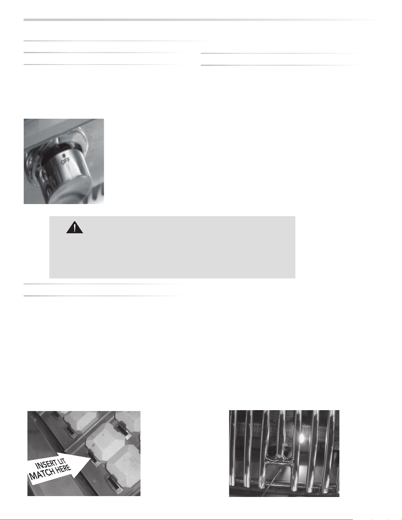
MANUAL LIGHTING
If a burner doesn’t light after several attempts, it can be
match lit using the lighting rod stored in the drip tray.
First, make sure you’ve returned all of the control knobs
to the OFF position and have allowed 5 minutes for any
accumulated gas to dissipate before attempting to match
light a burner.
To match-light this burner, use the lighting rod to insert a lit
match through the cooking grate into the front slot of the
briquette tray for that burner.
Push and turn the corresponding burner control knob to
“LITE”. If the burner doesn’t light within 5 seconds turn the
knob o and wait 5 minutes before attempting to light it
again.
Trident™ Burner
The Trident™ burner does not feature a manual lighting tube.
To match-light this burner, use the lighting rod to insert a lit
match through the cooking grate and through the protective
screen.
Push and turn the corresponding burner control knob to
“LITE”. If the burner doesn’t light within 5 seconds turn the
knob o and wait 5 minutes before attempting to light it
again.
INSTALLATION / USE & CARE
|
29
PRE-HEATING
Pre-heating your grill every time you use it is extremely
important. Pre-heating allows the briquettes to properly heat
up, providing more even and more consistent cooking results.
Pre-heat your grill by igniting all main burners, including the
ProSear™ burner, and setting them to “HI”.
Then close the hood and allow the grill to heat for 10 to
15 minutes. Once you’ve reached your desired pre-heat
temperature, turn o the burners that you won’t be using to
cook your food. Remember, surface temperature can be up
to 200° higher.
TYPES OF COOKING
The main ceramic burners and the Trident™ burner in your grill
are capable of creating a range of heat intensities. By varying
the heat output, the number of burners used and the position
of the hood, you can create either direct or indirect heat or a
combination of both and develop a wide variety of succulent
recipes. There are two basic types of grilling in an outdoor
grill... Direct Heat and Indirect Heat
Direct Heat
Direct heat cooking occurs when foods are placed directly
over the heat source. This form of heat is known as “radiant”
heat because the heat radiates directly from the source to the
food.
Direct heat is a must when you want to sear the outside of
your food to seal in fl avor. ProSear™ Burners provide the heat
necessary to sear foods and seal in fl avor.
Indirect Heat
Indirect heat cooking occurs when the food is not close to the
heat source. Heat reaches the food via air movement within
the cooking area. This form of heat is known as “convection”
heat.
Indirect, or “convection” cooking is achieved by placing
the food on one side of the grill and igniting burners on the
other side. You leave the burner below the food “OFF”. You
should keep the hood closed as much as possible during this
type of cooking to maintain even heat around the food. You
regulate the heat by adjusting the burner and using the hood
thermometer to monitor the temperature.
Professional restaurant chefs rely on a di erent type of heat
... infrared heat ... to create a higher searing temperature than
what standard burners can achieve. Lynx Grills provides the
Trident™ infrared burner.
Infrared burners work by focusing the gas fl ame through a
ceramic element fi lled with tiny holes.
These holes focus the fl ame on the surface of the element,
creating an intense heat much higher than that of a standard
brass burner. It allows you to sear your food more quickly
while leaving the inside rare, if desired.
The Trident™ burner, with its advanced components, requires
particular attention to lighting, usage and cleaning guidelines.
Pre-Heating the Trident™ Burner
Always preheat the entire grill before cooking to achieve
consistent, successful results. (See INDEX: “Preheating” for
further details.)
If the grill is already hot from cooking you should still pre-heat
the Trident™ burner for 2-3 minutes, or until it glows red.
Never place food over a Trident™ burner before it is fully pre-
heated because food particles and grease dripping onto a
cold Trident™ burner can clog the tiny ports and damage the
burner.
For the same reason you should minimize water spills on the
Trident™ burner and should not use water to control fl are-ups.
Take special care to minimize dropping any liquids on the
Trident™ burner while cleaning the cooking grids.
BASI
C
G
RILLIN
G
to
to
to
to
2
2
2
2
00
00
00
00
hi
hi
hi
hi
gh
gh
gh
gh
g
g
g
g
g
g
er
er
er
er
.
.
.
DO NOT LEAVE THE GRILL UNATTENDED DURING
THE PRE-HEAT CYCLE OR AT ANY TIME WHILE THE
GRILL IS IN USE.
PRE-HEATING FOR MORE THAN 15 MINUTES
MAY OVERHEAT THE GRILL, CAUSING DAMAGE TO
THE GRILL.
WARNING!
U
SIN
G
THE TRIDENT™ BURNER
30
|
INSTALLATION / USE & CARE
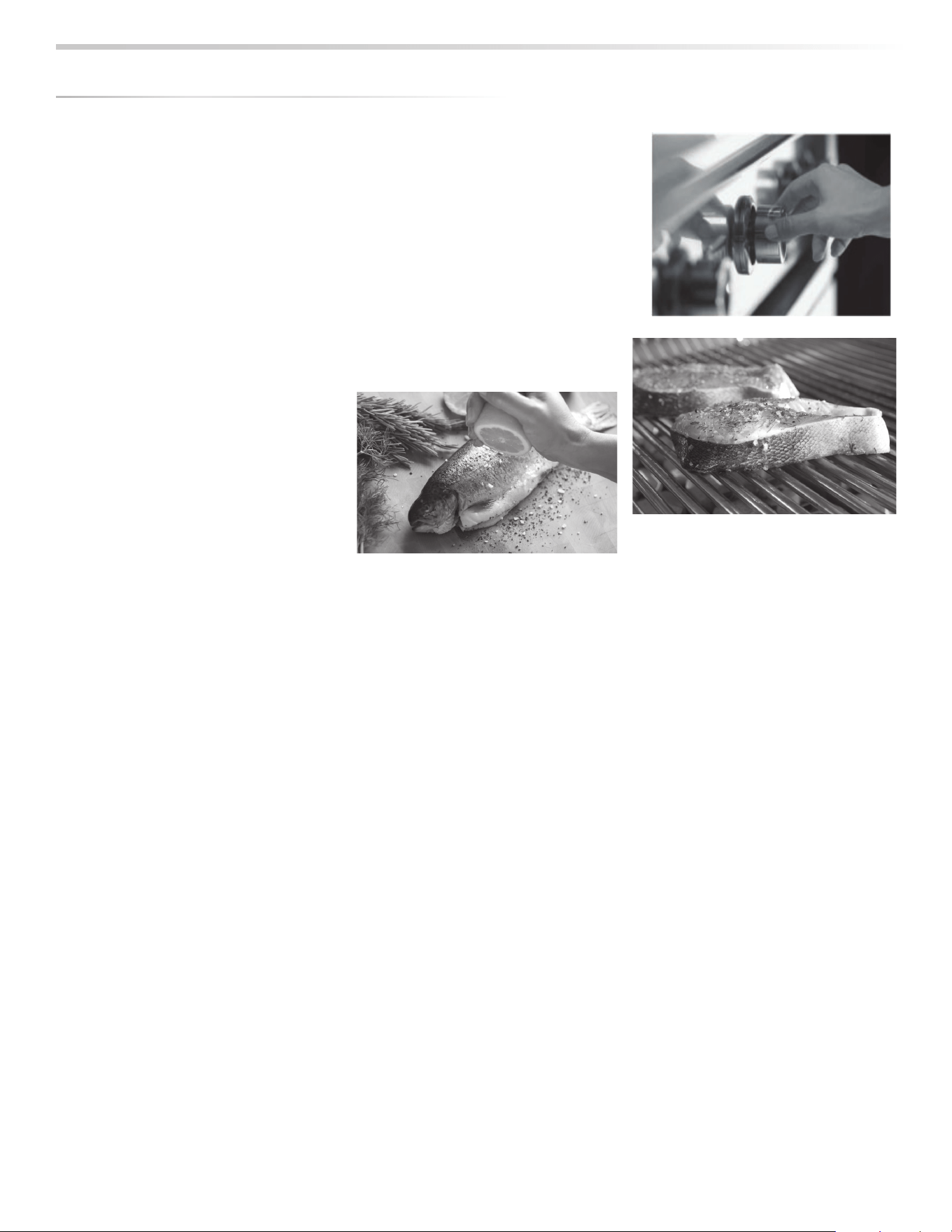
HOW TO SEAR
Searing locks in fl avor and juices while allowing the food’s
outer surface to absorb smoke and food-born aromas
produced when drippings are vaporized by the burner.
The result is a restaurant-style fi nish … crisp, fl avorful outside
with a tender, juicy inside.
While the ceramic burners in your grill are capable of
producing searing heat, the Trident™ infrared burner is
specifi cally designed for this purpose.
Rotisserie cooking
provides an even
delivery of heat to
your foods. It has no
equal. The constant
rotation not only cooks foods evenly, it also self bastes. As
juices rise to the surface of the food, they naturally fl ow
around it as it rotates. And, by moving the burner out from
beneath the food, you avoid scorching fl are-ups.
Your foods will be more evenly
cooked, more tender and juicier
when slow-roasted on a rotisserie.
The rotisserie system consists of
four main parts, the motor, the skewer, the forks and the
infrared burner.
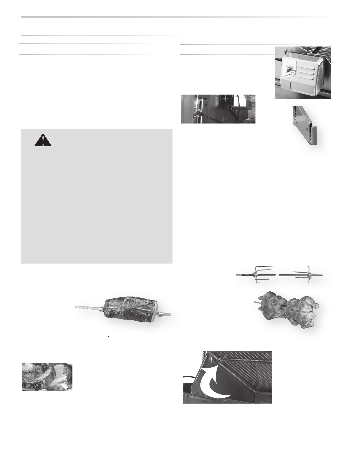
The Motor
Install the motor by sliding it into one
of the slots shown here. Use the top
slot for small foods or fast cooking
and the lower slot for large foods and
slower cooking.
Plug the motor power cord into the
motor and into the built-in power outlet
on the rear left panel. Your grill must
be plugged into an AC power supply
for the rotisserie to work.
Place a basting pan in the grill to prevent food accumulations
on the briquettes and burners. But BE SURE YOU REMOVE
IT before using any of the other burners.
The location of the rotisserie burner makes it more
susceptible to strong wind conditions (more so than the main
grill burners).
For this reason it features a safety valve that automatically
closes any time the rotisserie burner is not properly lit … like
if it were to extinguish in windy conditions. During windy
conditions, it’s best to keep the lid closed and to periodically
check the burner.
When the rotisserie
is not in use the
rotisserie motor
should be stored in a cool
dry location.
The Skewer & Forks
The rotisserie can handle
large food items up to 50
lbs. You should prepare any
item and fi rst mount it on the skewer.
y
y
g
g
Grill cooking grids are heavy duty. Dropping them
on the Trident™ Burner will damage the burner. Such
damage is not covered by the product warranty and
will cause a fi re, burns or other personal injury.
TRIDENT™ CLEANING
It’s easy to keep your Trident™ Burner operating at
peak performance. Just run it on “HI” with the hood
open for 15 minutes after each use to burn away
any food particles or drippings.
Any ash accumulation on the burner screen can be
removed with a light brush (like a paint brush) or
vacuum … BUT WAIT UNTIL THE BURNER IS COOL!
SAFETY PRECAUTIONS
USIN
G
THE TRIDENT™ BURNER
USIN
G
THE R
O
TISSERIE BURNER
o
oks foods evenly, it also self bastes. As
sh
dr
Th
Th
la
r
lbs
cool
k
Rotisserie
Motor Mount
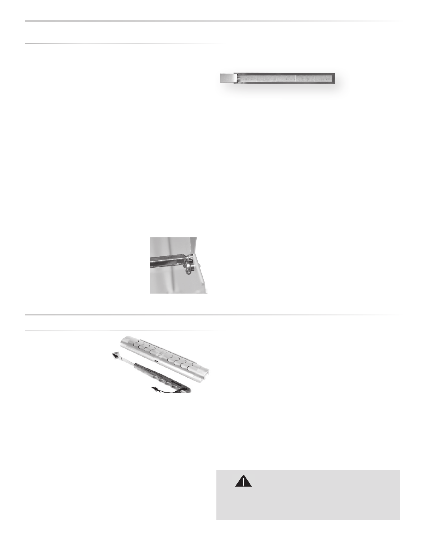
INSTALLATION / USE & CARE
|
31
Swing the warming rack up and out of the way. It will rest in
place.
Then mount the skewer on the grill before lighting the
rotisserie infrared burner. Lighting the burner fi rst could
result in burning your hands while trying to mount the skewer
on the grill.
It’s okay to remove the grill racks and even the briquette
trays to make room for large foods on the skewer.
To load the skewer, slide one of the forks onto the skewer.
Push the skewer through the center of the food, then slide
the second fork onto the skewer. Center the food to be
cooked on the skewer then push the forks fi rmly together.
Tighten the thumb screws (use pliers if necessary). You
should wrap any loose, dangling pieces of food (like wings)
with butcher’s string (never use nylon or plastic string).
With the food secured to the skewer slowly roll the skewer in
the palms of your hands to check for balance. It should rotate
smoothly. If you fi nd it has a heavy side, adjust where the
skewer pierces the meat. An unbalanced skewer will cause
uneven rotation and uneven cooking.
It’s normal for the skewer to fl ex with
large foods.Slide the pointed end of
the skewer into the motor and rest the
other end on the rollers on the other
side of the grill.
The notched portion of the skewer must rest on the rollers
for proper operation.
The Rotisserie Burner
To light the rotisserie infrared burner, fi rst mount the
skewered food item on the grill then follow the rotisserie
lighting procedure. (See INDEX: “Rotisserie Burner, Lighting”
for further details.)
Once lit, the rotisserie burner should reach cooking
temperatures in about 1 minute. It will glow evenly across its
surface in about 5 minutes.
NOTE: The grill thermometer should not be used for
rotisserie cooking. It is not designed to read direct infrared
heat.
If the burner will not stay lit when you release the control
knob, re-light it and hold the control knob in for at least 60
seconds to allow the thermocouple to heat up.
If, after holding the control knob in for at least 60 seconds,
the burner still will not stay lit when releasing the control
knob, call for service.
(See INDEX: “Obtaining service” for further details.)
Shut o all other burners while using the rotisserie burner.
USIN
G
THE R
O
TISSERIE BURNER
...
c
o
n
t
in
u
e
d
Must rest
on rollers
The Rotisserie Burner
Professional chefs far and
wide set their restaurant
cuisine apart by cooking
over wood fi res. Imparting a
delicate hint of wood smoke
enhances food, raising your
culinary skills to the next
level. Now you can impart that same culinary touch using
the smoker/steamer accessory.
Your new grill comes with the Lynx Smoker Set with handle.
This oval shaped Lynx Smoker box can be placed anywhere
on the grates directly over any burner. The unique handle
and interlock mechanism is designed to allow quick removal
or refi lling of the Lynx smoker box.
The smoker box is designed with special draft and fl ow
through for maximum smoke. It is constructed of 304 Heavy
Gauge Stainless Steel for years of use.
The Lynx Smoker box can be used with smoker pellets
or wood chips. Whether using wood chips or pellets, we
recommend using approximately 3 oz. of either material.
There is no need for presoaking, just fi ll the smoker box.
Now use the handle to place the smoker box directly on the
hot grates. Don’t forget to remove the smoker handle before
closing the grill lid.
Smoke occurs at approximately 575 degrees F. at the grilling
surface. Set the burner knob to medium/medium low to
achieve this temperature. Control the smoking by adjusting
the heat and being careful not to adjust it too high.
For best results keep the lid closed. The best absorption
of smoke fl avor occurs early in the cooking process. When
fi nished with smoking, allow the smoker box to cool and
dispose of remnants.
USING THE SMOKER BOX
OKER
BOX
Handle the smoker box with care. The cover
becomes extremely hot when in use. Use sturdy,
properly insulated gloves or dry pot holders.
CAUTION
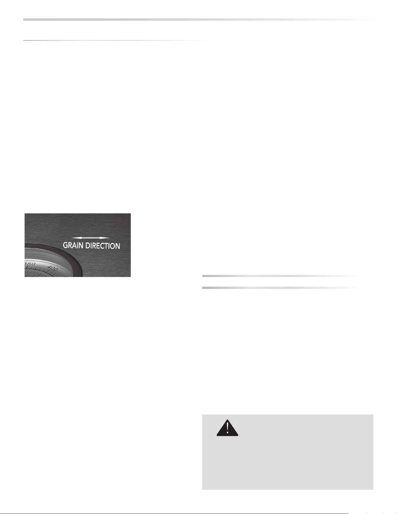
32
|
INSTALLATION / USE & CARE
STAINLESS STEEL
Our products are known for their attractive appearance. We
achieve this by selecting only the fi nest grades of stainless
steel and applying exacting workmanship.
In order to maintain this attractive appearance over the life of
the grill it is important to take the following steps:
• After each use wipe down the exterior of the grill to
remove grease and splatters.
• Be sure to follow the cleaning instructions for keeping the
grates and burners clean and ready for use.
• Use a commercially available Stainless Steel cleaner to
clean and polish the exterior surfaces.
Doing these things on a regular basis minimizes the amount
of e ort required.
Part of the appeal of your Grill is the fi ne grain fi nish. When
removing stubborn stains:
• Do not use metallic abrasives and always rub in the
direction of the grain.
• Some household cleaning products are not suitable for
stainless steel; be sure to read the label before using on
your Grill.
• Always use the mildest cleaning solution fi rst, scrubbing in
the direction of the grain. Specks of grease may gather in
the grain of the stainless steel and bake on to the surface,
giving the appearance of rust.
To remove these baked-on foods use a fi ne to medium
grit non-metallic abrasive pad (Scotch Brite is good) in
conjunction with a stainless steel cleaner.
• Solutions used for cleaning concrete and masonry can be
very corrosive and will ‘attack’ stainless steel. Ensure your
products are well protected before you allow the use of
such chemicals near your grill.
SPECIAL NOTE FOR LOCATIONS NEAR POOLS AND
COASTAL AREAS:
The 304 stainless steel material used in the construction
of the grill is highly rust resistant, however, chlorine in the
air from swimming pools or the salt from sea air may cause
surface rust to appear and even create some pitting if left on
the product.
Here are a few tips to avoid this:
• Regularly wipe down the exterior surfaces with a damp
cloth. (Micro fi ber cloths perform very well).
• Allow the surfaces to dry before installing the cover. Do not
cover a damp grill.
• In extreme environments apply a rust inhibitor which
leaves a microscopic protective layer on the grill. Products
that provide a layer of vapor corrosion inhibitors (VpCI™)
protect the surface very well.
• For seasonal storage use the product referred to above,
ensure the grill is dry and then cover and secure the cover
to minimize the amount of damp air getting to the surfaces.
THE LIMITED LIFE TIME WARRANTY PROVIDES
PROTECTION AGAINST RUST THROUGH OF PARTS THAT
RENDER THE PRODUCT INOPERATIVE. IT DOES NOT
COVER OCCASIONAL SURFACE RUST OR STAINING DUE
TO ENVIRONMENTAL CONDITIONS.
After your fi rst use certain areas of the grill may discolor from
the intense heat given o by the burners - this is normal and
cannot be cleaned o .
For light and heavy food stains there are many di erent
stainless steel cleaners available.
DRIP TRAY
The drip tray should be cleaned after each use. After the grill
is completely cool, remove the drip tray by pulling it out until
it stops, then lifting the front edge until the drip tray comes
free.
Clean it with hot soapy water or an oven-style cleaning
product and re-install. When using an oven-style cleaning
product be sure to carefully follow the manufacturer’s
instructions. Many of these cleaners are toxic and can
damage the stainless steel fi nish if not used properly.
Also, check the tray after rain. If you’ve left the grill
uncovered, you may need to remove the drip tray drain
plug to drain the water from the tray. The drain plug can be
removed with a fl at-head screwdriver.
C
LEANIN
G
Y
O
UR
G
RILL
DO NOT ALLOW EXCESS GREASE OR LIQUIDS TO
ACCUMULATE IN THE DRIP TRAY AS THIS MAY
CREATE A FIRE HAZARD.
NEVER USE GRILL WITHOUT DRIP TRAY PROPERLY
INSTALLED.
WARNING
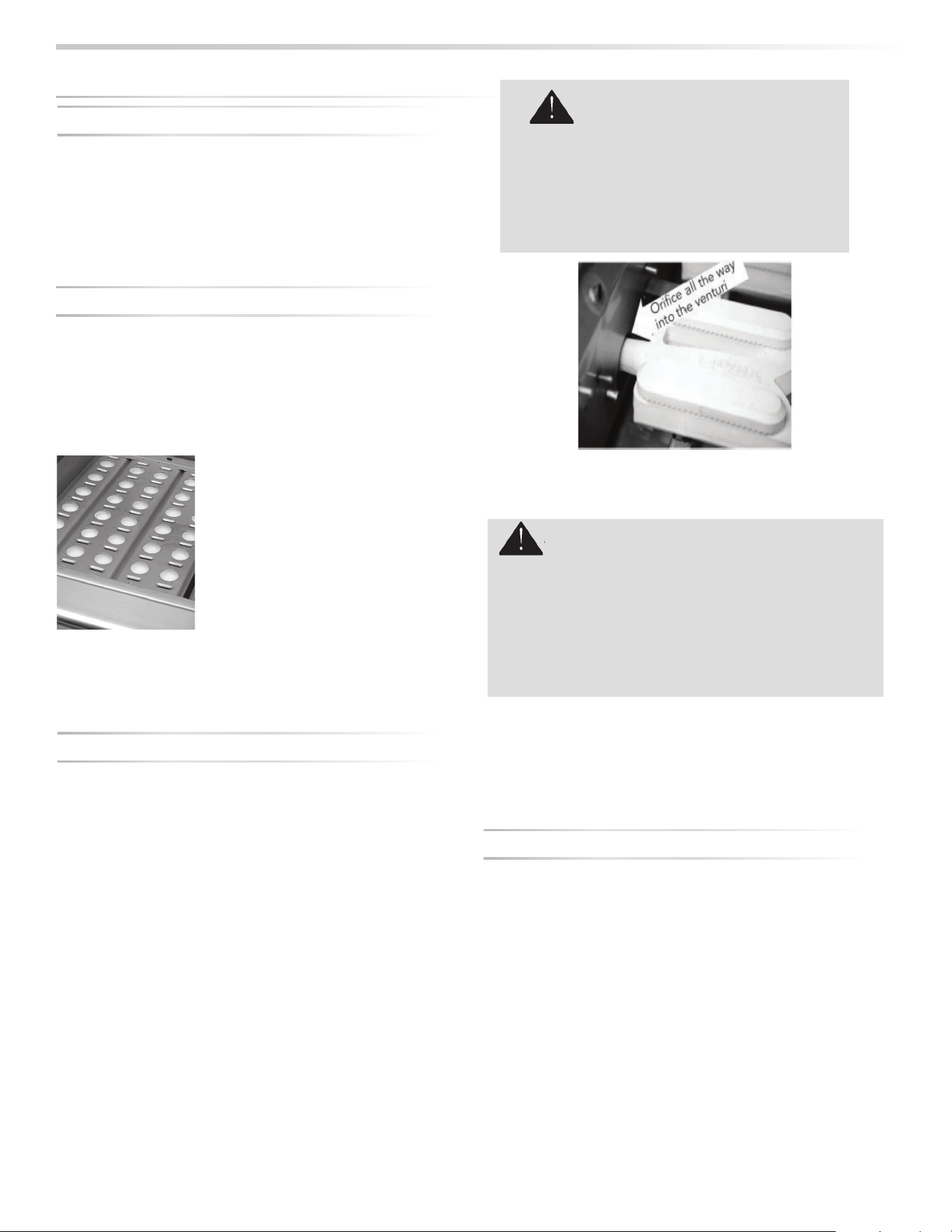
INSTALLATION / USE & CARE
|
33
PROPER PLACEMENT OF EACH BURNER IS
CRITICAL. AFTER CLEANING THEY MUST BE
CENTERED ON THE BRASS ORIFICE,
RESTING LEVEL WITHOUT ANY ROCKING.
FAILURE TO MEET THESE CONDITIONS MAY
CAUSE A VERY DANGEROUS CONDITION THAT
CAN CAUSE PERSONAL INJURY AND PROPERTY
DAMAGE.
WARNING
GRILLING RACKS
The easiest way to clean the grill racks is to do so
immediately after turning o the burners, while they are
still hot. Wearing a long BBQ mitt to protect your hand from
steam, dip a brass bristle brush in hot water and scrub the
grill rack. Dip the brush frequently because the steam helps
remove baked-on foods.
CERAMIC BRIQUETTES
The ceramic briquettes normally burn o any accumulated
food drippings. But you may occasionally experience larger
spills that don’t burn o under normal use.
When this happens, let the grill cool completely. Remove the
racks and then the briquette trays by lifting the front edge
and pulling them toward you.
Flip the trays over and put them
back in place over the burner.
Light the burners and set them to
“HI” for 5 - 10 minutes to burn the
briquettes clean. Any remaining
food items can be brushed o using
a soft brush.
Be sure the trays have completely
cooled before reinstalling them.
Replacement briquette trays can be ordered from your
dealer.
MAIN CERAMIC BURNERS
Make sure the grill is completely cool before proceeding.
Ensure that the gas supply is o and all control knobs are in
the “OFF” position.
To Remove Ceramic Burners:
Remove the grill racks and briquette trays.
Remove the burner caps to prevent accidental breakage.
Lift the burner up until the legs exit the frame.
Then pull to the rear of the grill so the burner head comes o
the brass orifi ce at the front.
Angle the burner sideways and lift it out.
To Clean the Ceramic Burner:
To maximize grill performance, clean the exterior of the
burner with a nylon brush when cooled. Clear any clogged
ports by lifting the ceramic burner caps and cleaning any
debris at the port holes.
Shake out any debris through the venturi or burner cap
opening.
Use a fl ashlight to inspect the burner inlet to ensure it is not
blocked. If obstructions can be seen, clean it with a paper
clip or a pipe cleaner.
C
LEANIN
G
Y
O
UR
G
RILL
...
co
n
t
in
u
e
d
1. to perform required maintenance will void your warranty
2. Clean out port holes on all ceramic burners if necessary with
a plastic scouring pad.
3. Scrape the bottom of the fi rebox with a plastic utty knife or
similar toll and discard the residue.
4. Clean out the burner orifi ces and ensure they are free of
debris.
5. Clean the drip tray.
WARNING - REQUIRED MAINTENANCE
W
TRIDENT™ BURNER
It’s easy to keep your Trident™ burner operating at peak
performance. Just run it on “HI” with the hood open for 5
minutes after each use to burn away any food particles or
drippings.
Any ash accumulation on the burner screen can be
removed with a light brush or vacuum … BUT WAIT UNTIL
THE BURNER IS COOL!
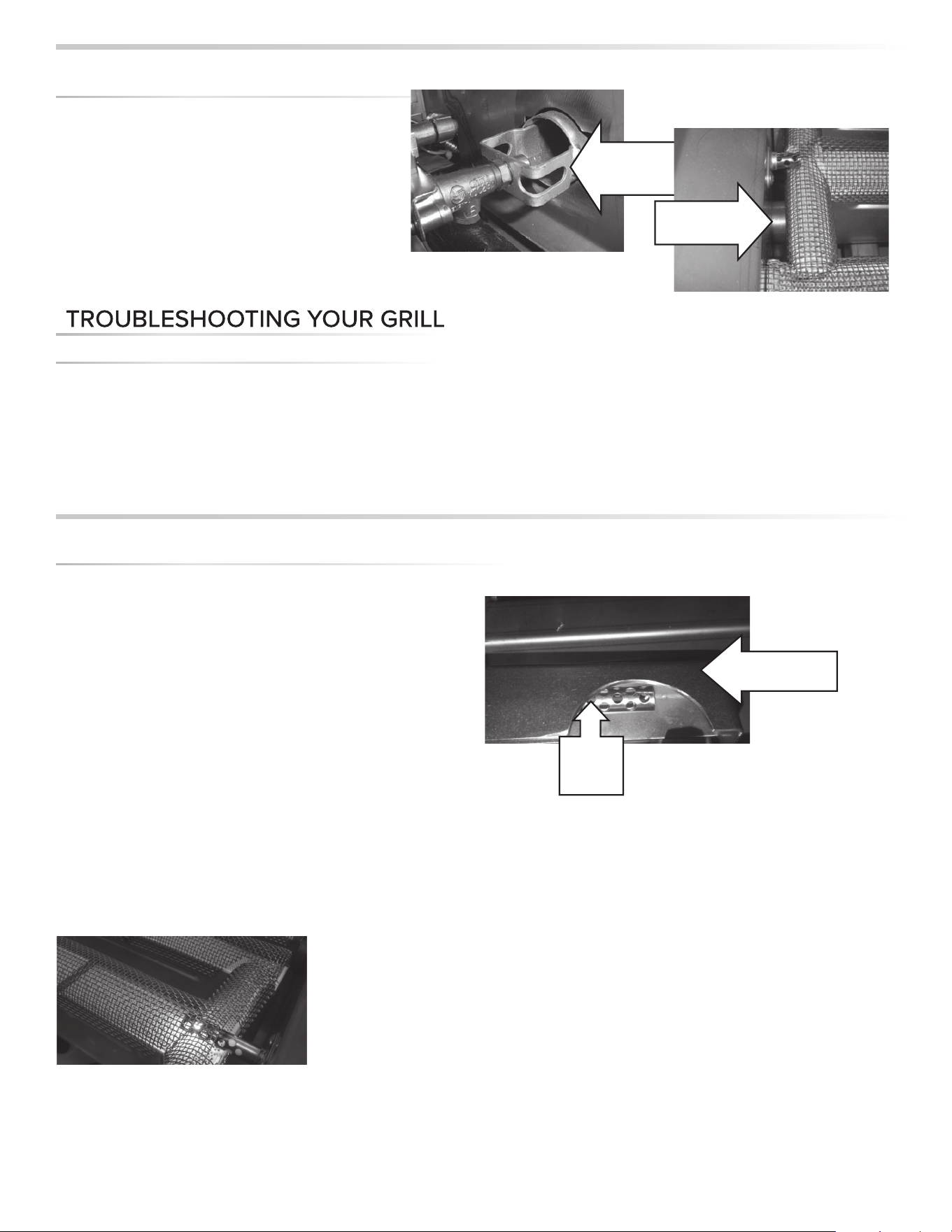
34
|
INSTALLATION / USE & CARE
BEFORE YOU CALL FOR SERVICE
Please check a few things before calling for service:
• Is there fuel supplied to the grill?
• Is the main shut-o valve open?
• Are you using the correct type of fuel? (LP or Natural Gas)
(See INDEX: “Gas Requirements” for further details.)
• Is your propane cylinder empty? Have you recently refi lled
the propane cylinder? If so, is the connection tight?
• Have you opened the valve on the propane cylinder?
• Is the grill plugged in to a live electric circuit?
If you’ve checked the above items, review the trouble-
shooting list below before calling for service.
GRILL WON’T LIGHT
First, confi rm that the grill is getting electricity by turning on
the lights, then:
Check The Igniters
Your grill uses an electric ignition system that does not spark.
Instead, the igniters should glow constantly when a control
knob is pushed in.
• Ensure that all burner controls are set to OFF.
• Remove the cooking grates and briquette trays.
• Watch an igniter as you push in and hold the
corresponding control knob. You will need either a small
mirror or shiny metal object to see the igniter under its
cover.
(Be sure you push in the correct control knob and keep the
knob in the “OFF” position).
• Check the remaining igniters. If igniters don’t glow,
proceed with troubleshooting or match-light the burner.
Check The Burners
If the igniters are working check to see if gas is reaching the
burners by attempting to match light a burner.
BE CAREFUL! IF THE BURNER FAILS TO IGNITE, WAIT
5 MINUTES BEFORE ATTEMPTING TO IGNITE OTHER
BURNERS! (See INDEX: “Match Lighting” for further
details.)
If match lighting doesn’t work, re-check fuel connections for
leaks and ensure the supply is of the correct type and is of
adequate pressure. (See INDEX: “Leak Test Procedure” for
further details.)
If the burner will light with a match, then the igniter may not
be functioning correctly. Call for service.
If the burner will not match light, and you know you are
getting gas, wait for any gas to dissipate and remove the
burner and check it for blockages.
P
O
TENTIAL PR
O
BLEM
S
Gas Collector
Hood
Hot
Surface
Igniter
CLEANIN
G
YOUR
G
RILL
...
c
o
n
t
in
u
e
d
Heat Shield
Removed,
Orifi ce/Venturi
Position
Inside View, Orifi ce
all the way into
venturi
Every 3 to 6 months, remove the burner and
inspect the venturi (inlet) and orifi ce to ensure
that they’re free of obstructions.
Food debris on the inside of the burner can be
gently shaken out. Do not touch the ceramic
surface.
When re-installing the Trident™ burner, be sure to
correctly

INSTALLATION / USE & CARE
|
35
SMELL OF GAS WHILE COOKING
IF YOU SMELL GAS WHILE THE GRILL IS OPERATING,
IMMEDIATELY TURN OFF ALL BURNERS AND SHUT OFF
THE MAIN FUEL SUPPLY.
• Perform a leak test (See INDEX: “Leak Test Procedure” for
further details.)
• Check for blockages (See INDEX: “Clean the Brass
Burner” for further details.)
YELLOW FLAMES
A yellow fl ame on the main burners indicates a lack of air.
But, if the air around the grill is dusty or if heavy grease is
present, some orange tips on the burner fl ame are normal.
• Adjust The Air Shutter
To adjust for insu cient air, adjust the air shutter. (See
INDEX: “Air Shutter Adjustment” for further details.)
LOW OR INSUFFICIENT HEAT
No part of the grill should ever be lined with aluminum foil.
Doing so will interfere with airfl ow and can cause a low heat
condition.
Ensure that you’ve preheated the main burners for at least
10 to 15 minutes with the hood closed and the ProSear™
burner for 3 minutes.
Proper leveling during installation is critical. A grill that
is out of level will cause erratic burner combustion and
ine cient, uneven heating. A carpenter’s spirit level
should be used to level the grill both front-to-back and
side-to-side.
If the low heat problem persists:
• Check the gas supply line sizing requirements.
• Check the gas supply line for kinks or damage.
REPLACE any damaged supply lines.
• Check the Regulator
Make sure that the regulator & hose assembly is the one
designed for and supplied with your grill and that it is
correctly set up for the type of fuel you are using. (See
INDEX: “Regulator Conversion” for further details.)
The hose and regulator provided must be used if your grill
is set-up for an LP Gas Cylinder. Ensure the LP hose is not
behind the grill.
Check that there is no physical pressure being applied to
the regulator attached to the back of the grill. The regulator
contains a fl exible diaphragm and should not be allowed to
touch the grill body or its surroundings.
• Check for Obstructions
Ensure that the burners and drip tray are clean and free from
obstructions.
LP (Propane) units:
• Is the cylinder almost empty?
Almost-empty cylinders may not have su cient pressure to
run the burners at high heat.
• Have the line pressure checked by a qualifi ed technician
(See INDEX: “Gas Requirements” for further details.)
• Flow Limiting Device
Improper lighting procedures may have activated the LP
cylinder’s fl ow control device, reducing the heat output.
To reset the fl ow control:
• Shut o all burner controls and close the LP cylinder valve.
• Wait 30 seconds and, very slowly, reopen the cylinder
valve.
• Wait a few seconds and relite a burner.
Bulk LP cylinder users:
Bulk LP cylinder lines must be properly regulated.
Ensure that you are using a 4/11 appliance regulator supplied
by Lynx and converted to LP gas. Also ensure that you do
not have more than one regulator in line.
Natural Gas units:
• Supply Line
Ensure that the supply line is at least 3/4” inside diameter or
1” outside diameter.
• Check line pressure
Natural gas inlet pressure should be at least 5” W.C. and
manifold pressure not less than 4” W.C. under full load (with
all burners on.)
• Check burners for blockages.
• Check fl ame characteristics. (See INDEX: “Flame, Correct
Size” )
P
O
TENTIAL PR
O
BLEM
S
...
c
o
n
t
in
u
e
d
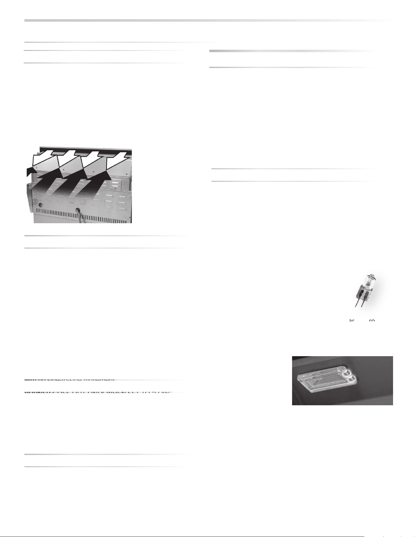
36
|
INSTALLATION / USE & CARE
WIND HITTING GRILL
Wind hitting the grill while in use, especially winds blowing
into or across the hood gap from behind, can cause poor
performance and in some cases can cause the control panel
to get dangerously hot.
Steady or gusty winds can prevent the normal exhaust of
hot gases. Locate your grill away from prevailing winds and
avoid grilling in windy conditions.
BURNER GOES OUT
• Location
First determine if the problem is being caused by location. If
the grill is subject to high winds, reposition it to provide some
protection.
• Check the Flame
Check the gas supply and fl ame characteristics. (See INDEX:
“Flame, Correct Size”)
• Burners Seated
Check to ensure that the burners are correctly positioned in
the grill. (See INDEX: “Burner Placement” for further details.)
Correctly-installed burners should be seated fi rmly and level
with no side-to-side movement.
BURNER GOES OUT ONLY WHEN SET TO “LOW”
The valves on the grill feature an adjustable low setting.
Fluctuations in gas pressure, gas conversion and even in the
quality of the gas itself may a ect burner performance at the
“LOW” setting. It could be either too high or too low. (See
INDEX: “Burner Adjustment” for further details.)
ROTISSERIE WON’T LIGHT
Follow the same procedure as described for the grill burners
to diagnose problems with the rotisserie burner.
BE CAREFUL! The rotisserie burner fl ame may be hard to
see in bright sunny conditions.
ROTISSERIE LIGHTS BUT GOES OUT AS SOON AS
CONTROL IS RELEASED
• Check Thermocouple
The control knob must be held in for 30 to 60 seconds after
ignition for the rotisserie burner to stay lit. (See INDEX:
“Lighting Rotisserie Burner” for further details.)
If the burner will not stay lit when you release the control
knob, re-light it and hold the control knob in for at least 60
seconds to allow the thermocouple to heat up.
If, after holding the control knob in for at least 60 seconds,
the burner still will not stay lit when releasing the control
knob, call for service. (See INDEX: “Obtaining service from
Lynx” for further details.)
LIGHTS WON’T LIGHT
• Check Power
Ensure that the grill is connected to a live AC power source
and check for rotisserie motor operation.
• Reset Transformer
Disconnect power from the grill and wait 5 minutes for the
transformer to cool down and reset. Then reconnect power.
If, after resetting the transformer and replacing bulbs, you still
do not have power, call for service.
• Replace the Bulb
Replacement bulbs are halogen, 12 volt, 10W
max, T3 type with a G4 bi-pin, and are readily
available at most stores. The glass cover is
held in place by two spring tension tabs. The
bulbs are easily removable without the use of tools. Simply
grasp the glass lens at the outer corners, near the front
tension clips and push the lens back. Then, swing the lens
down and pull it loose. You may have to loosen the screw to
remove the lens.
Avoid touching the glass
of a new bulb. Halogen
bulbs are very sensitive
to the oils found in human
skin. Touching the bulbs
may shorten their life.
Pull the bulb straight out from the socket without twisting.
Hold the bulb using a paper towel or other cloth and gently
press it straight into the socket. The glass cover should be
gently snapped back into place.
P
O
TENTIAL PR
O
BLEM
S
...
c
o
n
t
in
u
e
d
o
ols. Simply
ar
t
he
f
ro
nt
Pull on
spring
tabs to
release
light
cover
B
BU
RN
N
ER
G
OE
E
S OUT ONLY
W
W
HE
E
N SET
TO
“LO
W
W”
w
wi
th
n
n
o si
de
-t
o
o-
side movem
en
n
t

INSTALLATION / USE & CARE
|
37
CONTACTING CUSTOMER SERVICE
If service is required, call your authorized service agency.
Have the following information readily available.
• Model number
• Serial number
• Sotware Version
• Date purchased
• Name of dealer from whom purchased
Clearly describe the problem that you are having. If you are unable to obtain the name of an authorized service agency, or if
you continue to have service problems, contact Lynx at 1-888-289-5969, or write to:
Lynx Grills
62201 Hwy 82 West
Greenwood, Mississippi 38930 USA
Record the following information indicated below. You will
need it if service is ever required. The serial number and
model number can be located on the rating plate which is
located on the underside of the drip tray and on the heat shield
behind the front panel.
Record the information indicated below. You will need it if service is ever required.
Model number ________________________________________________________________________
Serial number _________________________________________________________________________
Software version ______________________________________________________________________
Date of purchase ______________________________________________________________________
Date installed _________________________________________________________________________
Dealer’s name ________________________________________________________________________
Dealer's Address ______________________________________________________________________
If service requires installation of parts, use only authorized parts to ensure protection under the warranty.
KEEP THIS MANUAL FOR FUTURE REFERENCE.
LYNX GRILLS, LLC
Greenwood, Mississippi 38930
THIS DESIGN CERTIFIED UNDER ANSI Z21.58; CSA 1.6 OUTDOOR COOKING GAS APPLIANCE
NAT. 4” (996 Pa) LP/PROP 10” WCP (2492 Pa)

38
|
INSTALLATION / USE & CARE
LYNX LIMITED WARRANTY
I. Limited Lifetime Warranty
The stainless steel grill body, ceramic grill burners, cooking
grates,Trident TM burner and rotisserie infrared burner
are warranted to be free from defects in material and
workmanship when subjected to normal domestic use
and maintenance for the lifetime of the original purchaser.
This warranty excludes surface corrosion, scratches, and
discoloration which may occur during normal use. This
warranty is limited to the replacement of the defective parts,
with the owner paying a processing fee and all other costs
including labor. Failure to perform required maintenance will
void this warranty
II. Limited Five-Year Warranty
The following grill parts are warranted to be free from
defects in material and workmanship, when subjected to
normal domestic use and maintenance, for a period of fi ve
(5) years from the original date of purchase; warming racks,
spit rods, briquette trays, manifolds and gas valves. This
warranty is limited to the replacement of the defective parts,
with the owner paying a processing fee and all other costs
including labor.
Ill. Limited two-Year Warranty
All other grill com onents are warranted to be free from
defects in materia fand workmanship, when subjected to
normal domestic use and maintenance, for a period of two
(2) years from the original date of purchase. This warranty
is limited to the replacement of the defective parts, with the
consumer paying all labor costs.
IV. Limited One-Year Warranty
For a period of one (1) year from the original date of
purchase, Lynx will replace or repair parts found to be
defective at no cost to the original purchaser. This includes
the cost of shipping replacement parts and, where
necessary, service labor at prevailing local rates by a Lynx
authorized service person. Service will be provided during
normal business hours and must be authorized in advance
by Lynx.
V. Limitations & Exclusions
1) This Warranty shall apply to products purchased and
located in the United States and Canada. Products must
be purchased in the country where service is requested.
2) Warranty applies only to the original purchaser and may
not be transferred.
3) Warranty is in lieu of all other warranties expressed or
implied and all other obligations or liabilities related to the
sale or use of Lynx products.
4) Warranty shall not apply and Lynx is not responsible for
damage resulting from misuse, abuse, failure to provide
reasonable and necessary required maintenance, natural
disaster, animals, alteration of or tampering with the
appliance, accident, hostile environment, fl are-up fi res,
improper installation or operation, or an installation not in
accordance with the instructions contained in this manual,
or the local codes.
5) Lynx shall not be liable for incidental, consequential,
special or contingent damages resulting from its breach of
this written warranty or any implied warranty.
6) Some states do not allow limitations on how long an
implied warranty lasts, or the exclusions of or limitations
on consequential damages. This warranty gives you
specifi c legal rights and you may have other rights which
vary from state to state.
7) No one has the authority to add to or vary Lynx’s warranty,
or to create for Lynx any other obligation or liability in
connection with the sale or use of its products.
8) Limited to the replacement of defective parts with the
owner paying all other costs including labor.
VI. What is not covered: Lynx shall not be responsible for
and shall not pay for the following:
1) Installation or start-up, damages or problems caused by
improper installation or use;
2)Service by an unauthorized service provider;
3) Damage or repair due to service by an unauthorized
service provider or use of unauthorized parts;
4) Warranty does not apply to products installed in any
commercial or non-residential application. Examples
of excluded applications include, but are not limited to
day care centers, schools, bed and breakfast centers,
churches, private clubs, fi re stations, club houses,
common areas in multi-family dwellings, restaurants,
hotels, nursing homes, food service locations and
institutional food service locations. *Contact Lynx for
Common Area Warranty.
5) To correct normal adjustments or settings, due to
improper installation, commissioning or local gas supply
properties.
6) Shipping and handling costs, export duties, installation,
removal, or re-installation cost (RMA excluded).
7) Display models are sold “as is”. If you have purchased
a display model, please be advised that it is sold “as is”
and that it is subject to the following warranty exclusions:
any exterior or cosmetic damage is nonwarrantable;
any missing components will be replaced at consumers
expense; major handling damage to manifold, valve and
ignition system will be serviced at consumer’s expense; all
other warranties will remain in e ect.
8)The cost of a service call to diagnose complaint.
9) Modifi cation to Lynx product will void related warranties.
Please refer to Accessory Care & Use for respective
warranties.

INSTALLATION / USE & CARE
|
39
LYNX COMMON AREA LIMITED WARRANTY
The Lynx Limited Warranty covers residential
installations only and is non-transferable to any other party.
This warranty applies when the product is installed in
common areas where more than a single party has rightful
access to its use or in locations considered beyond normal
residential use such as B&B's, and private clubs.
THIS PROVISION EXCLUDES ALL COMMERCIAL
APPLICATIONS, INCLUDING, BUT NOT LIMITED TO
RESTAURANTS AND INSTITUTIONAL FOOD SERVICE
LOCATIONS.
I. Limited Five-Year Warranty
The stainless steel body, the solid ceramic grill burners
are warranted to be free from defects in material and
workmanship when subjected to normal use and
maintenance for a fi ve year period from the original
purchase date. This warranty excludes surface corrosion,
scratches, and discoloration which may occur during
regular use. This warranty is limited to the replacement of
the defective parts, with the consumer paying labor.
II. Limited One-Year Warranty
The structural integrity of the interior grill parts, exterior, and
drip pans are warranted to be free from defects in material
and workmanship, when subjected to normal domestic
use and service, for a period of one year from the date of
purchase. This warranty is limited to the replacement of
the defective parts, with the owner paying all other costs
including labor.
Ill. Limited Parts & Labor Warranty
All other grill com onents are warranted to be free from
defects in materia fand workmanship for a period of 90
days from the original date of purchase. Lynx will replace or
repair parts found to be defective at no cost to the original
purchaser. After the 90 day period Lynx will sell parts to
the holder of this warranty at Lynx contractor prices for an
additional 9 months.
IV. Limitations & Exclusions
1) This Warranty shall apply to products purchased and
located in the United States and Canada. Products must
be purchased in the country where service is requested.
2) Warranty applies only to the original location of
installation and may not be transferred.
3) Warranty is in lieu of all other warranties expressed or
implied and all other obligations or liabilities related to the
sale or use of Lynx products.
4) Warranty shall not apply and Lynx is not responsible
for damage resulting from misuse, abuse, failure to
provide reasonable and necessary required maintenance,
natural disaster, animals, alteration of or tampering with
the appliance, accident, hostile environment, fl are-up
fi res, improper installation or operation, or an installation
not in accordance with the instructions contained in this
manual, or the local codes.
5) Lynx shall not be liable for incidental, consequential,
special or contingent damages resulting from its breach
of this written warranty or any implied warranty.
6) Some states do not allow limitations on how long an
implied warranty lasts, or the exclusions of or limitations
on consequential damages. This warranty gives you
specifi c legal rights and you may have other rights which
vary from state to state.
7) No one has the authority to add to or vary Lynx’s warranty,
or to create for Lynx any other obligation or liability in
connection with the sale or use of its products.
8) Limited to the replacement of defective parts with the
owner paying all other costs including labor.
V. What is not covered: Lynx shall not be responsible for
and shall not pay for the following:
1) Installation or start-up, damages or problems caused by
improper installation or use;
2) Service by an unauthorized service provider;
3) Damage or repair due to service by an unauthorized
service provider or use of unauthorized parts;
4) To correct normal adjustments or settings, due to
improper installation, commissioning or local gas supply
properties;
5) Shipping and handling costs, export duties, installation,
removal, or re-installation cost (RMA exluded).
6) Display models are generally sold “as is.” If you have
purchased a display model, please be advised that it is
sold “as is” and that it is subject to the following warranty
exclusions: any exterior or cosmetic damage is non-
warrantable; any missing components will be replaced at
consumer’s expense; major handling damage to manifold,
valve and ignition system will be serviced at consumer’s
expense; all other warranties will remain in e ect.
7) T he cost of a service call to diagnose complaint.
8)Modifi cation to Lynx product will void related warranties.
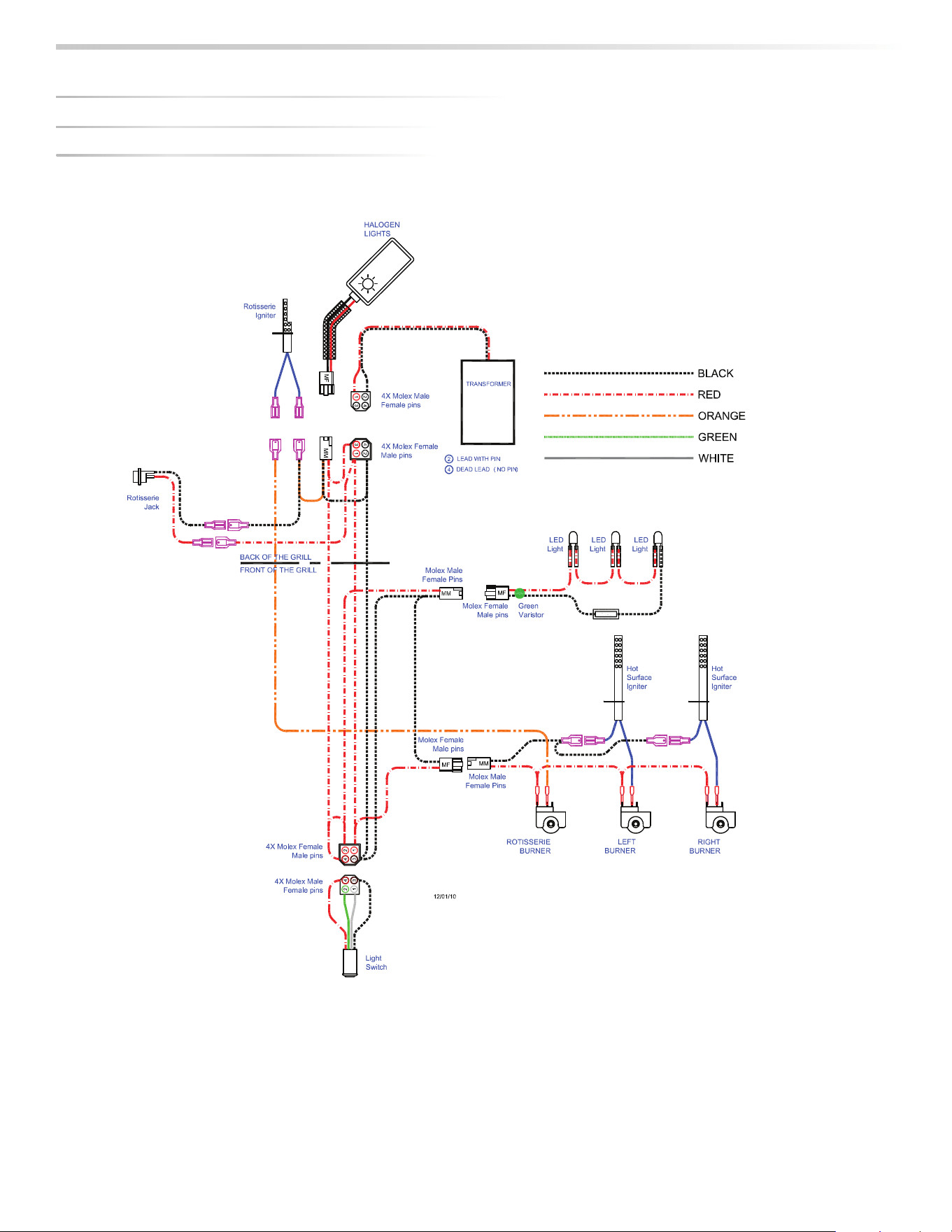
40
|
INSTALLATION / USE & CARE
27” / 30” ROTISSERIE GRILL
WIRIN
G
S
C
HEMATI
CS
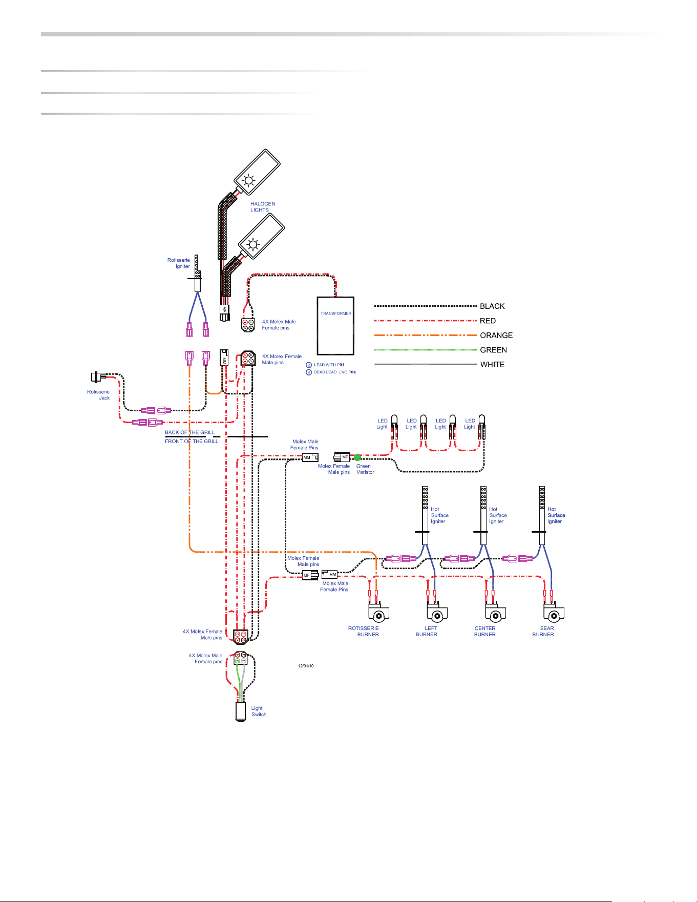
INSTALLATION / USE & CARE
|
41
36” & 42” ROTISSERIE GRILL
WIRIN
G
S
C
HEMATI
CS
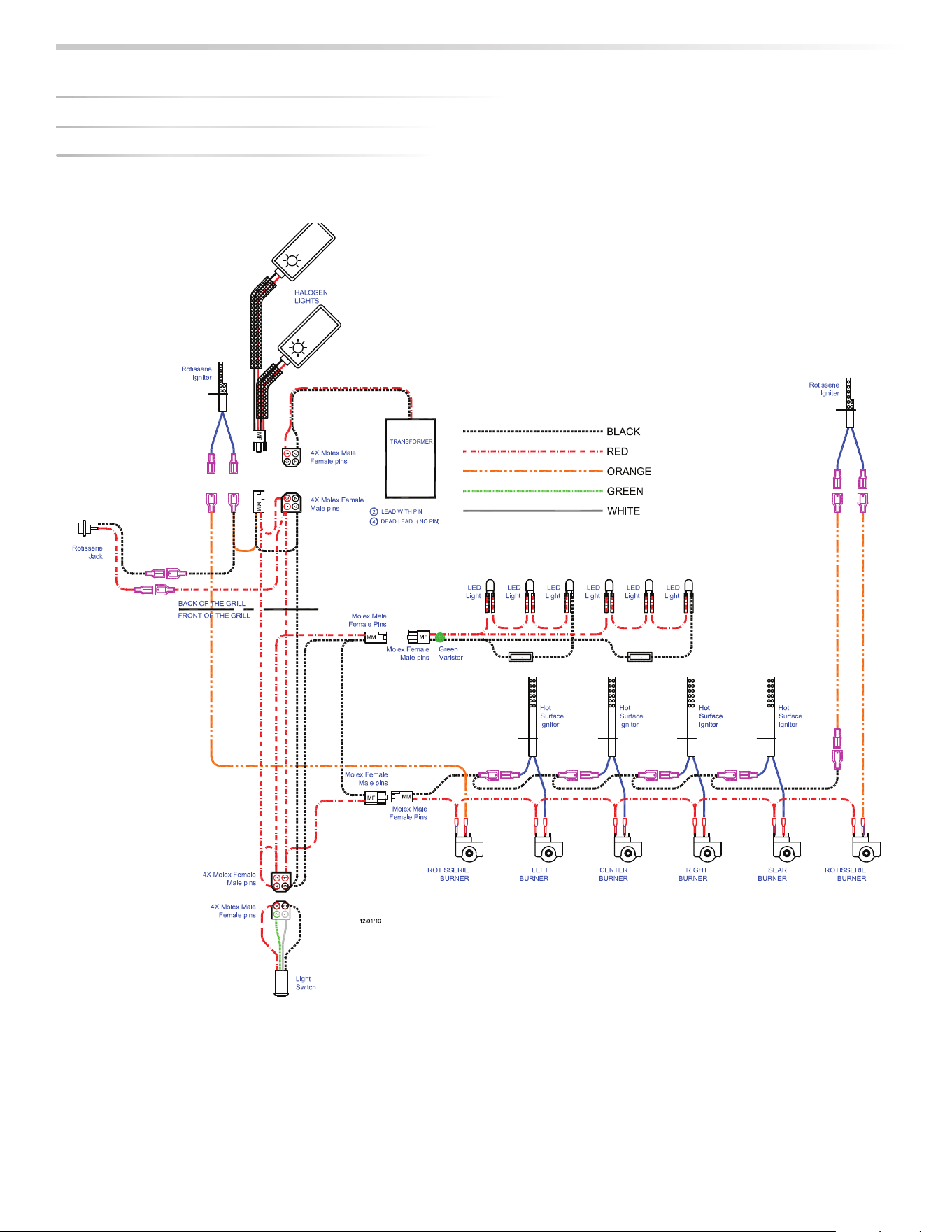
42
|
INSTALLATION / USE & CARE
54” ROTISSERIE GRILL
WIRIN
G
S
C
HEMATI
CS

INSTALLATION / USE & CARE
|
43

Lynx Grills
62201 Hwy 82 West
Greenwood, Mississippi 38930 USA
888-289-5969
www.lynxgrills.com
35283 Rev D (043021)