Loading ...
Loading ...
Loading ...
Installation
25
EN
Burner and nozzle specifications tables
5.6 Electrical connection
General information
Check the grid characteristics against the
data indicated on the plate.
The identification plate bearing the
technical data, serial number and brand
name is visibly positioned on the appliance.
Do not remove this plate for any reason.
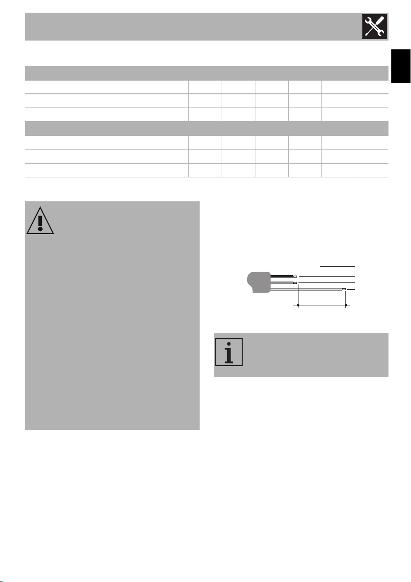
Perform the ground connection using a wire
that is 20 mm longer than the other wires.
The appliance can work in the following
modes:
• 220-240 V 1N~
3 x 1 mm² three-core cable.
Fixed connection
Fit the power line with an omnipolar circuit
breaker in compliance with installation
regulations. The circuit breaker should be
located near the appliance and in an easily
reachable position. For stationary
appliances permanently connected to the
fixed wiring, compliance with this
requirement is considered to be met if the
instruction concerning disconnection
incorporated in the fixed wiring is in
accordance with AS/NZS3000.
NG 1.0 kPA AUX SR RR R UR UR*
Nominal gas consumption (MJ/h)
4.3 6.1 9.3 10.4 15.1 21.6
Injector (1/100 mm)
0.95 1.10 1.35 1.50 1.80 2.20
Primary air (mm)
432544
ULPG 2.75 kPa AUX SR RR R UR UR*
Nominal gas consumption (MJ/h)
4.0 6.1 9.3 11.0 15.1 21.6
Injector (1/100 mm)
0.54 0.67 0.82 0.92 1.05 1.25
Primary air (mm)
10 10 10 10 10 10
Power voltage
Danger of electrocution
• Have the electrical connection
performed by authorised technical
personnel.
• Use personal protective equipment.
• The appliance must be connected to
earth in compliance with electrical
system safety standards.
• Disconnect the mains power supply.
• Do not pull the cable to remove the
plug.
• Use cables withstanding a temperature
of at least 90°C.
• The tightening torque of the screws of
the terminal supply wires must be 1.5 -
2 Nm.
The values indicated above refer
to the cross-section of the internal
conductor.
220-240V~
1 mm
2
20 mm
Loading ...