Loading ...
Loading ...
Loading ...
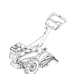
Retainer Bracket
Shoulder Bolt & Lock Nut
Figure 3
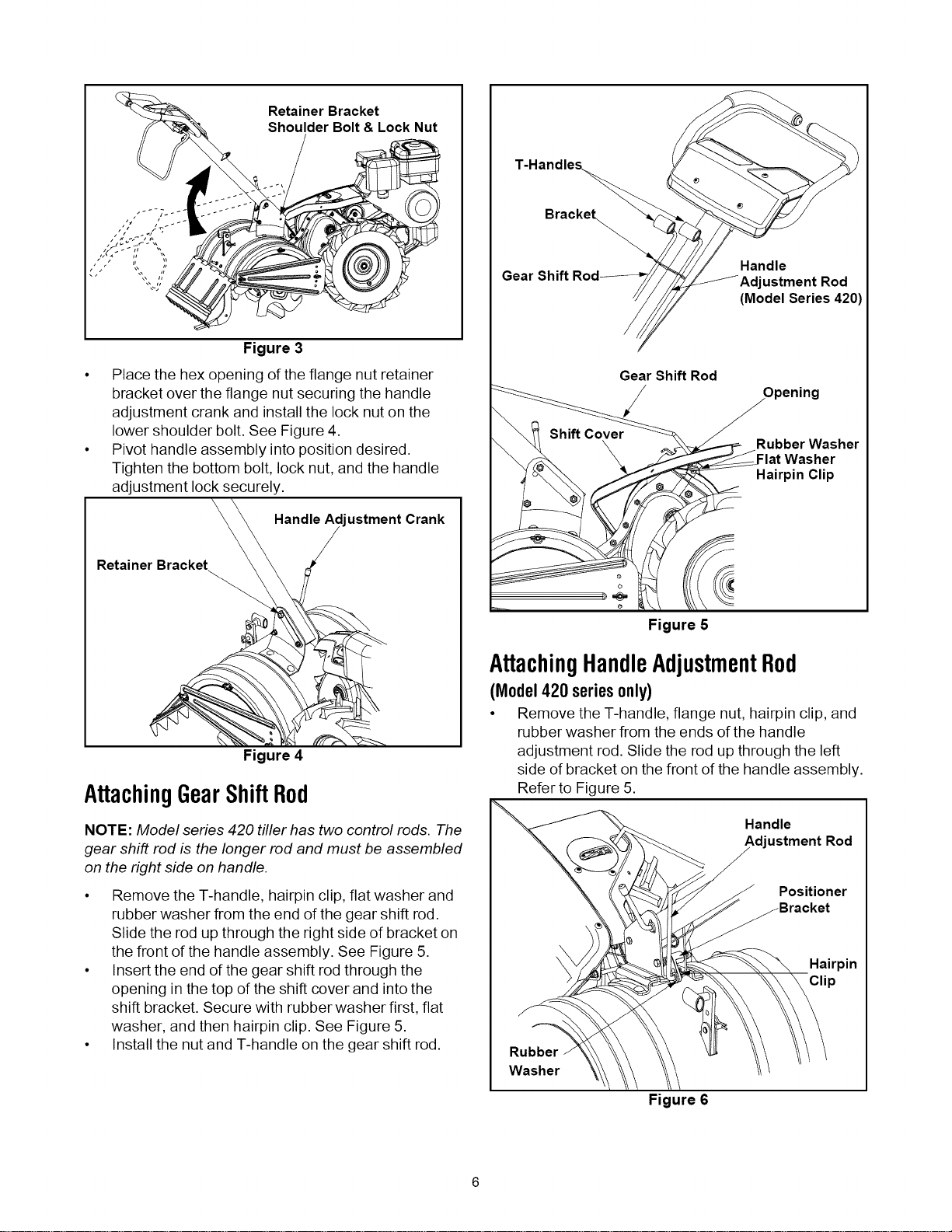
• Place the hex opening of the flange nut retainer
bracket over the flange nut securing the handle
adjustment crank and install the lock nut on the
lower shoulder bolt. See Figure 4.
• Pivot handle assembly into position desired.
Tighten the bottom bolt, lock nut, and the handle
adjustment lock securely.
Handle Ad ustment Crank
Retainer Bracket
Gear
Gear Shift Rod
/
Handle
ustment Rod
(Model Series 420)
Rubber Washer
-lat Washer
Hairpin Clip
Figure 4
AttachingGearShiftRod
NOTE: Model series 420 tiller has two control rods. The
gear shift rod is the longer rod and must be assembled
on the right side on handle.
• Remove the T-handle, hairpin clip, flat washer and
rubber washer from the end of the gear shift rod.
Slide the rod up through the right side of bracket on
the front of the handle assembly. See Figure 5.
• Insert the end of the gear shift rod through the
opening in the top of the shift cover and into the
shift bracket. Secure with rubber washer first, flat
washer, and then hairpin clip. See Figure 5.
• Install the nut and T-handle on the gear shift rod.
Figure 5
AttachingHandleAdjustmentRod
(Model420 seriesonly)
• Remove the T-handle, flange nut, hairpin clip, and
rubber washer from the ends of the handle
adjustment rod. Slide the rod up through the left
side of bracket on the front of the handle assembly.
Refer to Figure 5.
Handle
Adjustment Rod
Positioner
Rubber
Washer
Figure 6
Loading ...
Loading ...
Loading ...