
1
Owner’s Manual
NetDirector
®
1U
Rack-Mount 4K/60 Hz
HDMI KVM Switch
with Audio
8-Port Model: B024-H4U08
16-Port Model: B024-H4U16
1111 W. 35th Street, Chicago, IL 60609 USA • tripplite.com/support
Copyright © 2023 Tripp Lite. All rights reserved.
Este manual está disponible en español en la página de Tripp Lite: tripplite.com
Ce manuel est disponible en français sur le site Web de Tripp Lite : tripplite.com
WARRANTY REGISTRATION
Register your product today and be
automatically entered to win an ISOBAR
®
surge protector in our monthly drawing!
tripplite.com/warranty

2
Table of Contents
1. FCC Information 4
2. User Notice 4
3. Package Contents 4
4. Features 5
5. System Requirements 6
5.1 Console 6
5.2 Computers 6
5.3 Cables 6
5.4 Operating Systems 6
5.5 Components 7
6. Important Safety Instructions 10
6.1 General Safety Instructions 10
6.2 Rack-Mounting Safety 11
Instructions
7. Installation 12
7.1 Stacking 12
7.2 Rack Mounting 12
7.2.1 Front Rack-Mounting 12
7.2.2 Rear Rack-Mounting 14
7.3 KVM Switch Installation 16
7.3.1 Single-Stage Installation 16
7.3.2 Two-Stage Cascade Installation 17
7.3.3 Three-Stage Cascade Installation 18
7.3.4 Multi-Display Installation 20
7.3.5 Grouping Ports into Vertical 21
Channels
8. Basic Operation 22
8.1 Hot Plugging 22
8.1.1 Hot Plugging KVM Ports 22
8.1.2 Hot Plugging Console Ports 22
8.2 Port Selection 22
8.3 Port ID Numbering 22
8.4 PoweringOandRestarting 23
the KVM
9. OSD Operation 24
9.1 OSD Login 24
9.2 OSD Hotkey 24
9.3 OSD Main Screen 25
9.4 OSD Main Screen Headings 25
9.5 OSD Navigation 26
9.6 OSD Functions 26
9.6.1 F1: Go To 26
9.6.2 F2: List 27
9.6.3 F3: Set 28
9.6.4 F4: Admin 30
9.6.5 F5: SKP 33
9.6.6 F6: BRC 34
9.6.7 F7: Scan 35
9.6.8 F8: Logout 36
10. Hotkey Operation 37
10.1 Hotkey Port Control 37
10.2 Hotkey Setting Mode (HSM) 37
10.3 Select the Active Port 38
10.4 Auto Scan Mode 38
10.5 Skip Mode 39
10.6 Keyboard / Mouse Reset 39
10.7 Hotkey Beeper Control 39
10.8 HSM Hotkey Control 40
10.9 OSD Hotkey Control 40
10.10 Port OS Control 40
10.11 Restore Default Values 04
10.12 EDID Mode 41
10.13 Mouse Emulation Control 41
10.14 HSM Summary Table 41
11. Keyboard Emulation 43
11.1 Mac Keyboard 43
11.2 Sun Keyboard 44

3
Table of Contents
12. RS-232 Operation 45
12.1 Setup 45
12.2 RS-232 Pin Assignments 45
12.3 Console Login: HyperTerminal 46
12.4 RS-232 Commands 47
12.4.1 Verication 47
12.4.2 Login 47
12.4.3 Logout 48
12.4.4 Open/Close RS-232 Link 48
12.4.5 Set Baud Rate 49
12.4.6 Switch Port 49
12.4.7 Hotkey Setting 50
12.4.8 OSD Hotkey 51
12.4.9 USB Reset 51
12.4.10 Restore Default Settings 52
12.4.11 Firmware Upgrade 52
12.4.12 KVM Status 53
12.4.13 EDID Mode 54
12.4.14 Broadcast Mode 54
13. Firmware Management Utility 55
13.1 Downloading the Firmware 55
13.2 Preparation 55
13.3 Starting the Upgrade 56
13.4 Upgrade Successful 58
13.5 Upgrade Failed 58
13.6 Firmware Upgrade Recovery 58
13.7 OSDConguration 59
Backup/Restore
13.7.1 Backup 59
13.7.2 Restore 60
14. Appendix 60
14.1 B024-H4U08 and B024-H4U16 60
Connection Tables
14.1.1 B024-H4U08 (First Level) + 60
B024-H4U08 (Second Level)
14.1.2 B024-H4U16 (First Level) + 60
B024-H4U16 (Second Level)
14.1.3 B024-H4U08 (First Level) + 61
B024-H4U08 (Second Level) +
B024-H4U08 (Third Level)
14.2 Specications 62
14.3 Administrator Login Failure 63
14.4 Factory Default Hotkeys and 63
Settings
15. Warranty and Product 64
Registration

4
1. FCC Information
2. User Notice
3. Package Contents
This device complies with part 15 of the FCC Rules. Operation is subject to the following two conditions: (1) This
device may not cause harmful interference, and (2) this device must accept any interference received, including
interference that may cause undesired operation.
Note: This equipment has been tested and found to comply with the limits for a Class A digital device, pursuant to
part 15 of the FCC Rules. These limits are designed to provide reasonable protection against harmful interference
when the equipment is operated in a commercial environment. This equipment generates, uses, and can radiate
radio frequency energy and, if not installed and used in accordance with the instruction manual, may cause harmful
interference to radio communications. Operation of this equipment in a residential area is likely to cause harmful
interference in which case the user will be required to correct the interference at his own expense. The user must
useshieldedcablesandconnectorswiththisequipment.Anychangesormodicationstothisequipmentnot
expressly approved by Tripp Lite could void the user’s authority to operate this equipment.
Allinformation,documentation,andspecicationscontainedinthismanualaresubjecttochangewithoutprior
noticationbythemanufacturer.Themanufacturermakesnorepresentationsorwarranties,eitherexpressedor
implied,withrespecttothecontentshereofandspecicallydisclaimsanywarrantiesastomerchantabilityortness
for any particular purpose. Any of the manufacturer’s software described in this manual is sold or licensed “as is.”
Should the programs prove defective following their purchase, the buyer (and not the manufacturer, its distributor, or
its dealer), assumes the entire cost of all necessary servicing, repair and any incidental or consequential damages
resulting from any defect in the software.
The manufacturer of this system is not responsible for any radio and/or TV interference caused by unauthorized
modicationstothisdevice.Itistheresponsibilityoftheusertocorrectsuchinterference.
The manufacturer is not responsible for any damage incurred in the operation of this system if the correct operational
voltage setting was not selected prior to operation. VERIFY THAT THE VOLTAGE SETTING IS CORRECT
BEFORE USE.
• NetDirector B024-H4U08 / B024-H4U16 Rack-Mount KVM Switch with Audio
• (x2) DisplayPort 1.4 Cables
• (x2) USB 3.0 Cables
• (x2) Audio Cables
• Firmware Upgrade Cable
• Foot Pad Set (4 pc.)
• Power Adapter
• North America Power Cord
• EU Power Cord
• UK Power Cord
• Owner’s Manual
Check to ensure all components are present and in good order. If anything is missing, or was damaged in shipping,
contact your dealer.
Read this manual thoroughly and follow the installation and operation procedures carefully to prevent any damage to the
switch or to any other devices on the installation.

5
4. Features
• One USB console controls up to eight (B024-H4U08) or sixteen (B024-H4U16) DisplayPort interface computers and
two additional USB 3.0 peripheral devices.
• Cascadable to three levels – controls up to 512 computers (B024-H4U08) or to two levels--up to 256 computers
(B024-H4U16).
• Multi-Display feature – stack up to eight units and display video to up to 8 monitors (dual-display/triple-display/quad-
display/multi-display).
• Supports DisplayPort video output and allows you to choose an appropriate video output and deploy console with
exibility.
• Superior video quality – up to 4K DCI (4096 x 2160 @ 60 Hz) resolution.
• Built-in 2-port USB 3.1 Gen 1 hub with SuperSpeed 5 Gbps data transfer rates.
• Audio enabled – full bass response provides a rich experience for 2.1 channel stereo sound.
• Supports HD audio.
• Computer selection via pushbuttons, hotkeys, OSD, and RS-232 commands.
• Independent switching of KVM and USB peripheral focus.
• Two-level (administrator/user) password authorization for enhanced security protection.
• Broadcast mode – operations can be simultaneously performed on all selected computers, such as software
installation and upgrading, systemwide shutdown, etc.
• Auto Scan Mode for monitoring all computers.
• Console mouse port emulation/bypass feature supports most mouse drivers and multifunction mice.
• Multilingual keyboard mapping – supports English (US), English (UK), German (DEUTCH), German (SWISS), French,
Hungarian,Italian,Japanese,Korean,Russian,Spanish,Swedish,TraditionalChinese,andSimpliedChinese.
• Mac/Sun keyboard support and emulation.
• Supports hot-plugging.
• HDMI compliant and HDCP 2.2 compliant.
• Multi-platform support for Windows, Linux, Mac, and Sun operating systems.
• Firmware upgradable.
• Supports multimedia, wireless keyboards and mouse.

6
5. System Requirements
5.1 Console
• HDMI monitor capable of the highest possible resolution in the installation
Note: For multi-display installations, multiple monitors are required. See 7.3.4 Multi-Display Installation for details.
• USB mouse
• USB keyboard
• Speakers (optional)
5.2 Computers
• An HDMI card or built-in HDMI port
Notes:
• The quality of the display is aected by the quality of the HDMI card. For best results, we recommend you purchase a
high-quality product.
• For multi-display installations, multiple monitors are required. See 7.3.4 Multi-Display Installation for details.
• USB-A port
• Audio ports (optional)
5.3 Cables
Note: The quality of the display is aected by the quality and length of the cables.
• For multi-display installations, standard USB-A to USB-B cables and standard HDMI cables are also required
Note: The B024-H4U08 and B024-H4U16 supports speaker ports only. Do not connect the microphone connector from the
KVM cable sets.
5.4 Operating Systems
OS Supported Versions
Windows Windows Server 2008, 2012, 2016, 2019 / Windows 7 SP1 / Windows 8 /
Windows 8.1 / Windows 10
Linux CentOS 7 and higher
OpenSUSE Leap 15.1
Snapshot8
10.26 and higher
Ubuntu 16.0.4 and higher
NeoKylin v7.0
Sun Sun Soloaris 11.3 and higher
Mac 10.6 and higher
Notes:
• Supports Linux Kernel 2.6 and higher.
• The B024-H4U08 and B024-H4U16 have a built-in USB 3.1 hub. They do not support PCs or operating systems that do not support
USB 3.1.
7
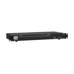
5.5 Components
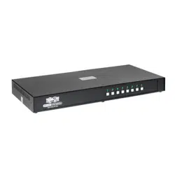
Front View
B024-H4U08
B024-H4U16
No. Component Description
1
Port Selection
Pushbuttons
For manual port selection:
• Press a port selection pushbutton for less than two seconds to bring the KVM, USB hub
and audio focus to the computer attached to its corresponding port.
• Press a pushbutton for longer than two seconds to bring the KVM and audio focus to the
computer attached to its corresponding port.
• Press pushbuttons 1 and 2 simultaneously for 2 seconds to perform a keyboard and
mouse reset. See section 10.6 Keyboard / Mouse Reset for details.
• Press pushbuttons 7 and 8 simultaneously for 2 seconds to start Auto Scan Mode.
2
Port LEDs The Port LEDs are built into the Port Selection Switches. The left ones are the KVM Port
LEDs; the right ones are the USB LEDs:
KVM
• Lights DIM ORANGE to indicate the computer attached to the corresponding port is up
and running (on line).
•FlashestoindicatethatFirmwareUpgrademodeisineect.
• Changes to BRIGHT ORANGE to indicate that the computer attached to its corresponding
port is the one that has the KVM focus (selected).
• Flashes to indicate that the computer attached to its corresponding port is being accessed
under Auto Scan mode.
USB
• Lights GREEN to indicate that the computer attached to its corresponding port is the one
that has access to the USB peripherals.
5. System Requirements
1
1
2
2
3
3
5
5
7
7
4
4
6
6
8
8

8
5. System Requirements
No. Component Description
3
Firmware
Upgrade
Recovery Switch
Duringnormaloperationandwhileperformingarmwareupgrade,thisswitchshouldbe
intheNORMALposition.Ifarmwareupgradeoperationdoesnotcompletesuccessfully,
thisswitchisusedtoperformarmwareupgraderecovery.Seesection13.6 Firmware
Upgrade Recovery for details.
4
Audio Jack The cables from your main speakers plug in here.
Note: The speakers plugged into the front-panel audio jack have priority over those in the rear panel.
5
Firmware
Upgrade Port
Thermwareupgradecablethattransfersthermwareupgradedatafromthe
administrator’s computer to the KVM switch connects to this RJ11 connector.
6
USB 3.1 Gen 1
Peripheral Hub
Section
USB 3.1 peripherals (printers, scanners, etc.) plug into this port (this may require an extra
power adapter).
Note: The USB 3.1 hub cannot be accessed through the switch by computers on the second level of a
cascaded installation.
7
Reset Button Pressing this switch performs a system reset. When the system resets, the switch beeps
andtheportLEDsashinsuccessionuntiltheresetiscomplete.Aftertheresetiscomplete,
you can login again.
Note: This switch is recessed and must be pushed with a small object, such as the end of a paper clip
or a ballpoint pen.
8
Power LED Lights to indicate that the switch is powered up and ready to operate.
9
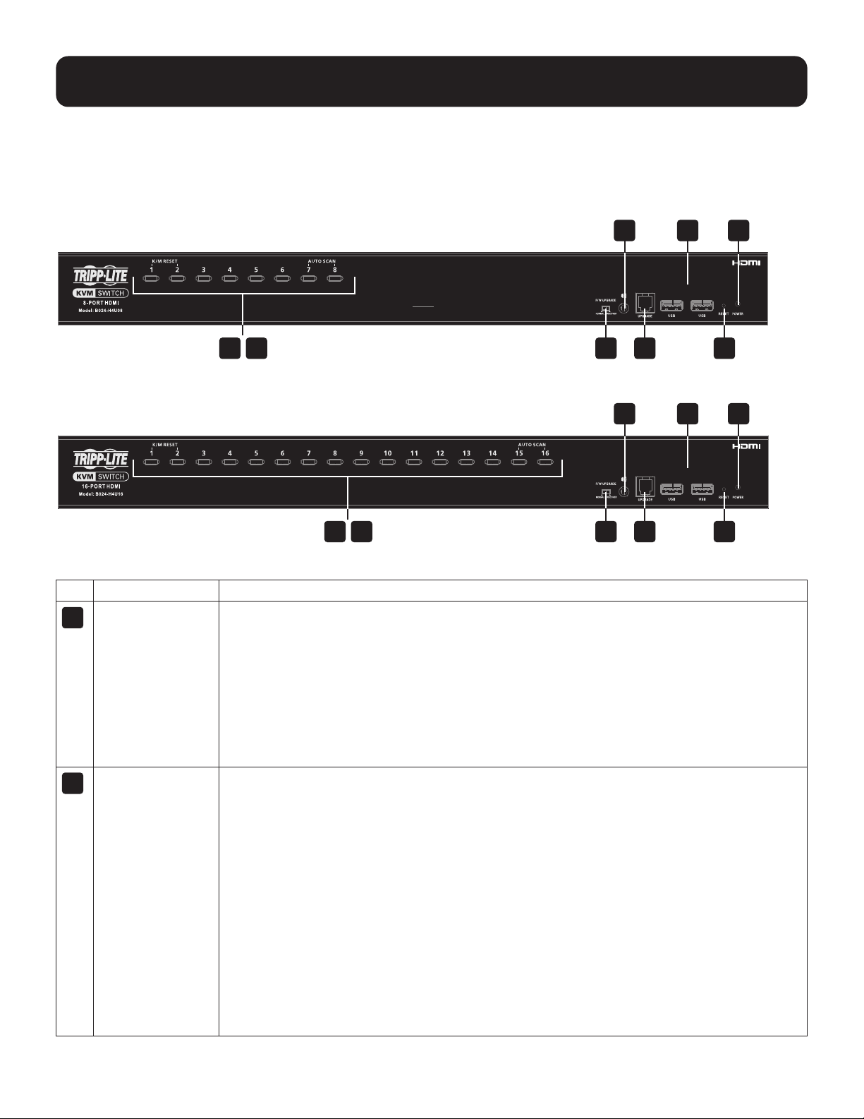
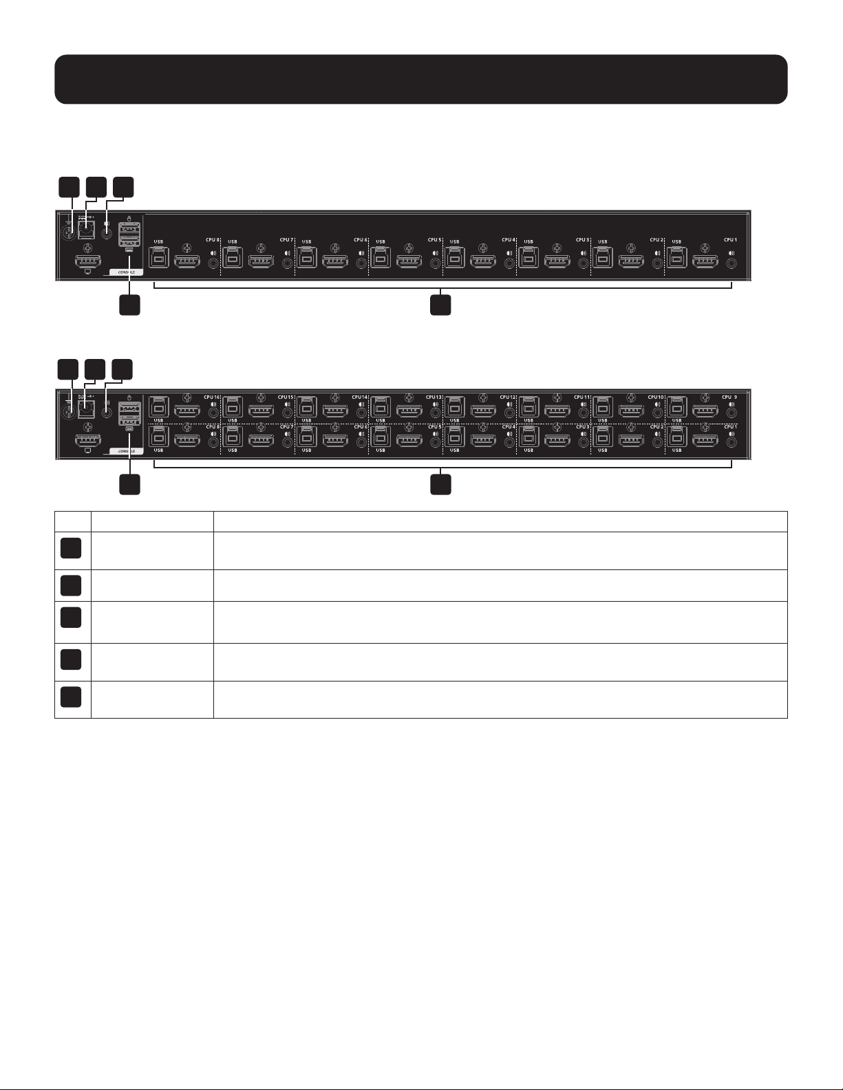
Rear View
B024-H4U08
B024-H4U16
No. Component Description
1
Grounding
Terminal
The grounding wire used to ground the switch attaches here.
2
Power Jack The power adapter cable plugs in here.
3
Audio Jack The cables from your main speakers plug in here.
Note: The speakers plugged into the front panel audio jack have priority over those plugged in here.
4
Console Port
Section
The cables from your console HDMI monitor, USB keyboard, USB mouse and speakers plug
in here. Each connector is marked with an appropriate icon to indicate itself.
5
KVM Port
Sections
The cables that link the switch to your computers plug in here. Each KVM port section is
comprised of a speaker jack, a USB-B port, and HDMI connector.
5. System Requirements
1 2 3
4 5
1 2 3
4 5

10
6. Important Safety Instructions
6.1 General Safety Instructions
• Read all of these instructions and save them for future reference.
• Follow all warnings and instructions marked on the device.
• Do not place the device on any unstable surface. If the device falls, serious damage will result.
• Do not use the device near water.
• Do not place the device near or over radiators or heat registers.
• The device cabinet is provided with slots and openings to allow for adequate ventilation. To ensure reliable operation
and protect against overheating, these openings should never be blocked or covered.
• The device should never be placed on a soft surface such as a bed, sofa or rug. Doing so will block the device’s
ventilation openings. Moreover, the device should not be placed in a built-in enclosure unless adequate ventilation has
been provided.
• Never spill liquid of any type on the device.
• Unplug the device from the wall outlet before cleaning. Use a damp cloth for cleaning. Do not use liquid or aerosol
cleaners.
• The device should be operated from the power source indicated on the marking label. If uncertain of the power
available, consult your dealer or local power company.
• The device is designed for IT power distribution systems up to 230V phase-to-phase voltage.
• As an added safety feature, the device is equipped with a 3-wire grounding type plug. If unable to insert the plug into
the outlet, contact an electrician to replace the obsolete outlet. Do not attempt to plug into a two-prong ungrounded
outlet. Always follow local/national wiring codes.
• Do not allow anything to rest on the power cord or cables. Route the power cord and cables to avoid them being
stepped on or tripped over.
• If an extension cord is used with this device, ensure the total ampere ratings of all products used on the extension
cord do not exceed its rated ampere rating. Also ensure all products plugged into the wall outlet do not exceed a total
of 15 amperes.
•Considerationshouldbegiventotheconnectionofequipmentandthesupplycircuit,aswellaswhateect
overloading the supply circuit might have on overcurrent protection and supply wiring.
• To help protect the system from unexpected transient increases and decreases in electrical power, use a Tripp Lite
Surge Protector, Line Conditioner, or Uninterruptible Power Supply (UPS).
• Position system cables and power cables carefully so nothing rests on any cables.
• When connecting or disconnecting power to hot pluggable power supplies, observe the following guidelines:
– Install the power supply before connecting the power cable to the power supply.
– Unplug the power cable before removing the power supply.
– If the system has multiple sources of power, disconnect power from the system by unplugging all power cables from
the power supplies.
• Never push objects of any kind into or through cabinet slots. They may touch dangerous voltage points or short out
partsresultinginariskofreorelectricalshock.
•Donotattempttoservicethedevice;referallservicingtoqualiedservicepersonnel.

11
6. Important Safety Instructions
•Ifthefollowingconditionsoccur,unplugthedevicefromthewalloutletandbringittoqualiedservicepersonnel
for repair:
– The power cord or plug has become damaged or frayed.
– Liquid has been spilled into the device.
– The device has been exposed to rain or water.
– The device has been dropped or the cabinet has been damaged.
– The device exhibits a distinct change in performance, indicating a need for service.
– The device does not operate normally when the operating instructions are followed.
• Only adjust controls covered in the operating instructions. Improper adjustment of other controls may result in
damagethatwillrequireextensiveworkbyaqualiedtechniciantorepair.
• Do not connect the RJ11 connector marked “UPGRADE” to a public telecommunication network.
• Use of this equipment in life support applications where failure of this equipment can reasonably be expected
tocausethefailureofthelifesupportequipmentortosignicantlyaectitssafetyoreectivenessisnot
recommended.
6.2 Rack-Mounting Safety Instructions
• The ambient operating temperature in the rack may be an issue and is dependent upon the rack load and
ventilation. When installing in a closed or multi-device rack assembly, ensure the temperature will not exceed the
maximum rated ambient temperature.
•Beforeinstallingtherack,ensurethestabilizersaresecuredtotherack,extendedtotheoorandthefullweight
oftherackrestsontheoor.Installfrontandsidestabilizersonasinglerackorfrontstabilizersforjoinedmultiple
racks before working on the rack.
•Alwaysloadtherackfromthebottomupwiththeheaviestitemloadedintotherackrst.
• When loading the rack, avoid creating a hazardous condition due to uneven loading.
• Ensure the rack is level and stable before extending a device from the rack.
• Use caution when pressing the rail release latches or sliding a device into or out of a rack; slide rails can pinch
yourngers.
• After a device is inserted into the rack, carefully extend the rail into a locking position, then slide the device into the
rack.
• Do not overload the AC supply branch circuit that provides power to the rack. The total rack load should not
exceed 80 percent of the branch circuit rating.
•Ensurethatproperairowisprovidedtodevicesintherack.
• Do not step on or stand on any device when servicing other devices in a rack.
• Caution! Slide/Rail (LCD KVM) mounted equipment is not to be used as a shelf or work space.
12
7. Installation
The B024-H4U08 and B024-H4U16 can be stacked on a desktop or rack mounted at the front or rear of a rack.
Notes:
• Allow at least 2 inches (5.1 cm) on each side for adequate ventilation and 5 inches (12.7 cm) at the rear for power cord and
cable clearance.
• The standard rack mounting kit does not include screws or cage nuts. If you need additional screws or cage nuts, contact your
rack dealer.
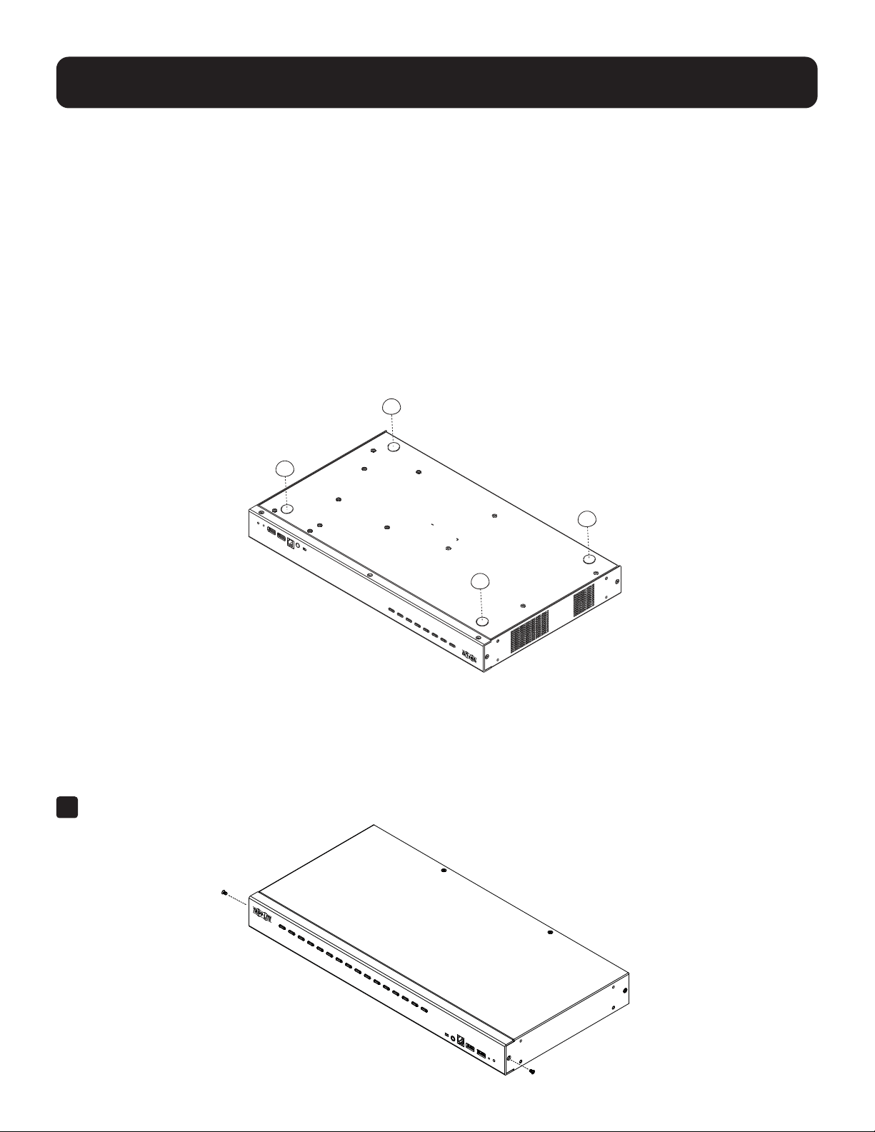
7.1 Stacking
The B024-H4U08 and B024-H4U16 can be placed on any level surface that can safely support the weight of the device
and the weight of the attached cables. Make sure the surface is clean and free of any materials that can block the
exhaust vents or otherwise interfere with normal operation of the switch.
To place the B024-H4U08 and B024-H4U16 (or to stack units if you are cascading them), remove the backing material
from the bottom of the rubber feet and stick them onto the bottom panel at the corners, as shown below:
7.2 Rack Mounting
7.2.1 Front Rack-Mounting
1
Remove each of the screws from the left and right sides near the front of the unit.
13
7. Installation
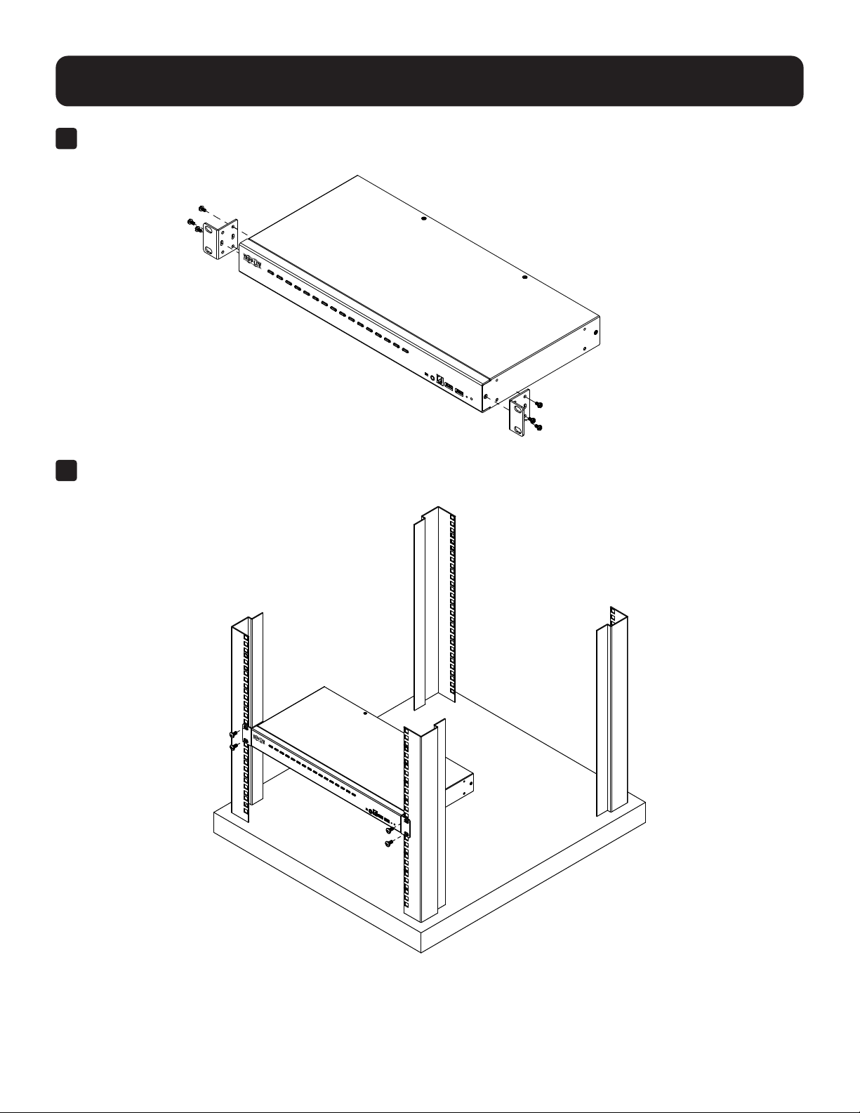
2
Use the M3 x 6 Phillips hex head screws supplied with the rack mounting kit to attach the rack mounting brackets
onto the sides near the front of the unit.
3
Place the KVM switch in the rack. Position it so that the holes in the mounting brackets line up with the holes in the
rack. Secure the mounting brackets to the front of the rack.
14
7. Installation
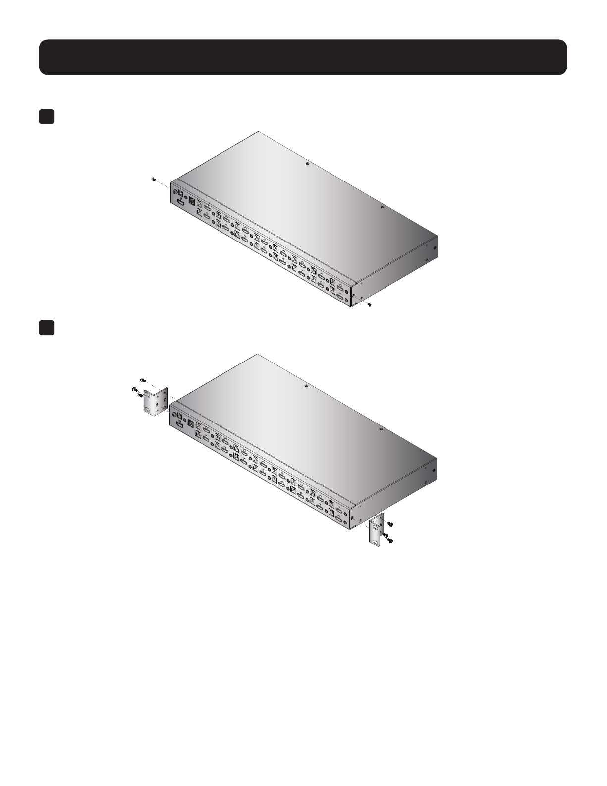
7.2.2 Rear Rack-Mounting
1
Remove each of the screws from the left and right sides near the rear of the unit.
2
Use the M3 x 6 Phillips hex head screws supplied with the rack mounting kit to attach the rack mounting
brackets onto the sides near the rear of the unit.
3
15
7. Installation
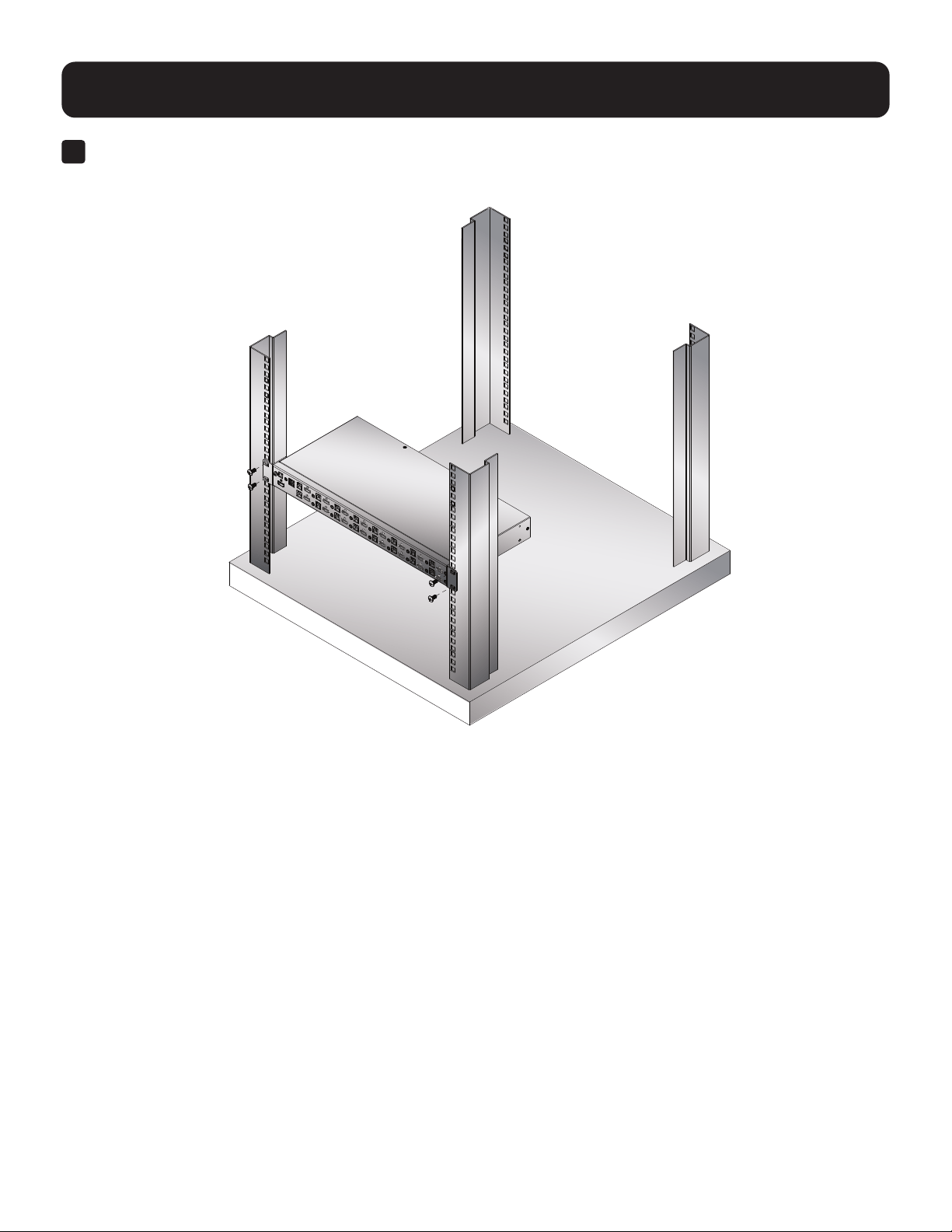
3
Place the KVM switch in the rack. Position it so that the holes in the mounting brackets line up with the holes in the
rack. Secure the mounting brackets to the rear of the rack.
16
7.3 KVM Switch Installation
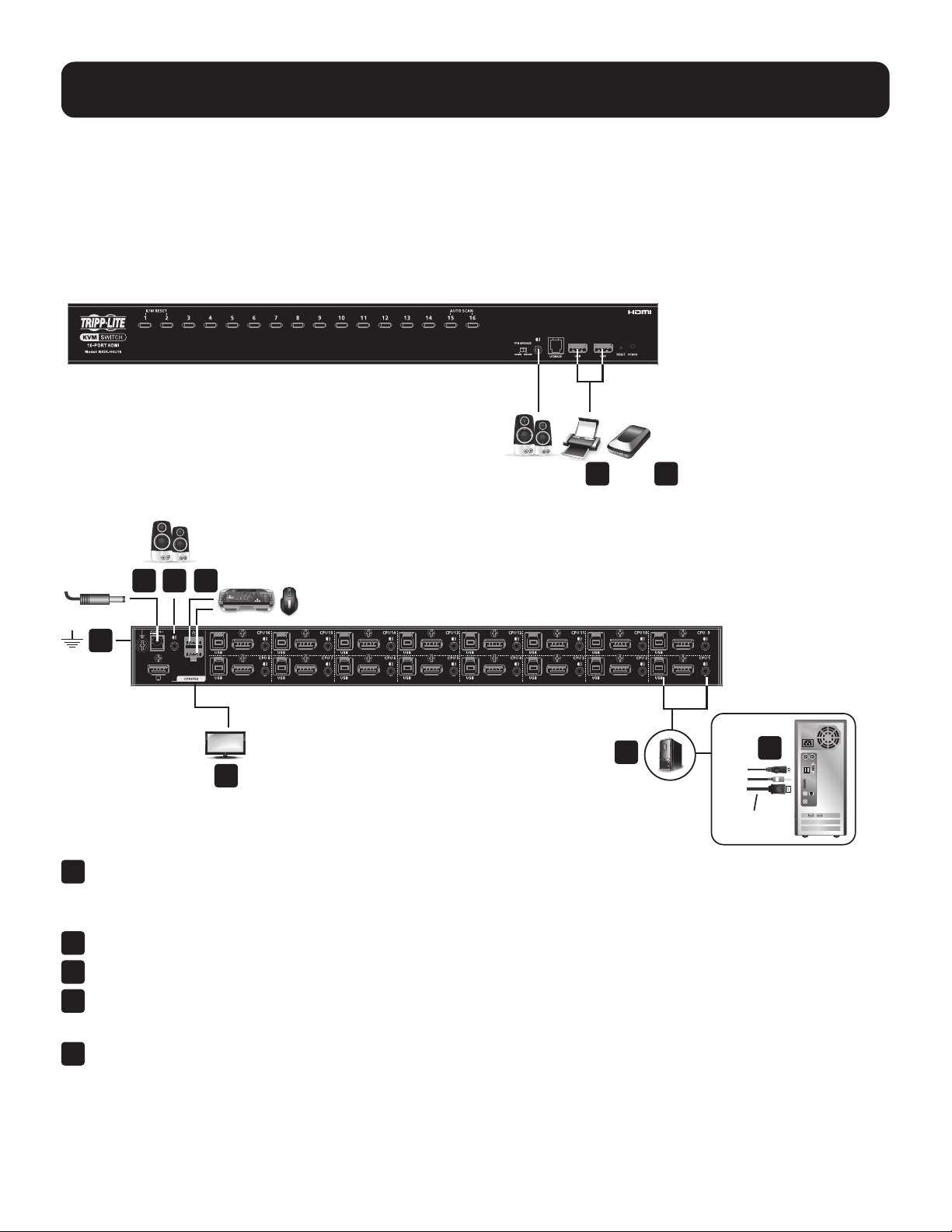
7.3.1 Single-Stage Installation
To set up the console KVM switch, refer to the following steps and installation diagram.
Note: B024-H4U16 model shown. The port locations are the same for the B024-H4U08, except for the number of KVM ports.
Front
Rear
1
Ground the KVM by connecting one end of a grounding wire to the KVM’s grounding terminal and the other end
to a suitable grounded object.
Note: Do not omit this step. Proper grounding helps to prevent damage to the unit from power surges and static electricity.
2
Plug your USB keyboard and USB mouse into the unit’s USB console ports.
3
Plug your HDMI monitor(s) into the HDMI console port, then power on the monitor(s).
4
Plug your speakers into the audio jacks located on the unit’s front and rear panel.
Note: The speakers plugged into the front panel have priority over those plugged into the rear panel.
5
Use the provided cable sets (HDMI cable, USB 3.0 cable and audio cable) with this package.
Plug the HDMI connector into any available HDMI port in the KVM Ports Section of the switch
(CPU 1, CPU 2, etc.), then plug the USB 3.0 cable and audio cable into their corresponding ports.
Notes:
• Verify that all the connectors are in the same KVM Ports Section (all in CPU 1, all in CPU 2.).
• The KVMs only support audio speakers. Do not connect a KVM cable’s microphone connector to the speaker ports.
7. Installation
4 7
48
1
2
3
5
6
HDMI Cable
17
7. Installation
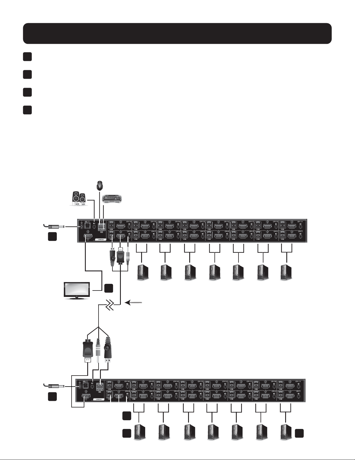
6
At the other end of the cables from step 5, plug the DisplayPort cable, USB 3.0 cable, and audio cables into their
respective ports on the computer. Repeat steps 5 and 6 for other PC systems you are installing.
7
(Optional) Plug your USB peripherals into the USB Type-A ports in the USB 3.1 Gen1 Peripheral Hub located on
the unit’s front panel.
8
Plug the power adapter that came with your switch into an AC power source, then plug the power adapter cable
into the KVM’s power jack.
9
Power on the computers.
Note: Make sure all computers and devices connected to the KVM are also properly grounded.
7.3.2 Two-Stage Cascade Installation
To control even more computers, additional KVM switches can be cascaded from the KVM ports of the First Stage unit.
The cascaded KVMs that connect back to the First Stage unit are considered Second Stage units. As many as 128
(B024-H4U08) or 256 (B024-H4U16) computers can be controlled in a complete two-stage installation. Tables showing
the relation between the number of computers and the number of units needed to control them is provided in section
14.1 B024-H4U08 and B024-H4U16 Connection Tables.
7
6
3
4 5
2
USB HDMI
KVM Cable Set

18
7. Installation
1
Make sure that power to all the devices you will be connecting—including all preexisting devices on the
installation—hasbeenturnedo.
2
Use the provided cable sets (HDMI cable, USB 3.0 cable, and audio cable) to connect the First Stage unit to the
console ports of the Second Stage unit.
Note: Plug the USB Type-A connector into the lower USB (keyboard) port in the Console section (they are both marked with a
similar icon to remind you of the correct USB port).
3
Using another provided cable set (HDMI cable, USB 3.0 cable and audio cable), plug the HDMI connector into any
available HDMI in the KVM Ports Section of the second stage switch, then plug the accompanying USB Type-B
cable and audio cable into their corresponding USB and audio jacks.
Notes:
• Verify all connectors are in the same KVM Ports Section (all in CPU 1, all in CPU 2, etc.) and that each port is marked with an
appropriate icon to indicate itself.
• The KVMs only support audio speakers. Do not connect a KVM cable’s microphone connector to the speaker ports.
4
At the other end of the cables from step 3, plug the HDMI cable, USB 3.0 cable and audio cables into their
respective ports on the computer.
5
Repeat steps 3 and 4 for any other PC systems you are installing.
6
For each Second Stage unit, plug the power adapter cable into its Power Jack, then plug the power adapter into an
AC source.
7
Plug the First Stage unit’s power adapter cable into its Power Jack, then plug the power adapter into an AC source.
8
Power on the computers.
Notes:
• The power-on sequence requires that Second Stage units be powered on rst. After they are all powered on, the First Stage units
must be powered on next. Only after all KVM switches have been powered on in this sequence can the computers be powered on.
• The USB 3.1 hub cannot be accessed through the switch by computers on the second level of a cascaded installation.
• Make sure the computers and devices connected to the KVMs are also properly grounded.
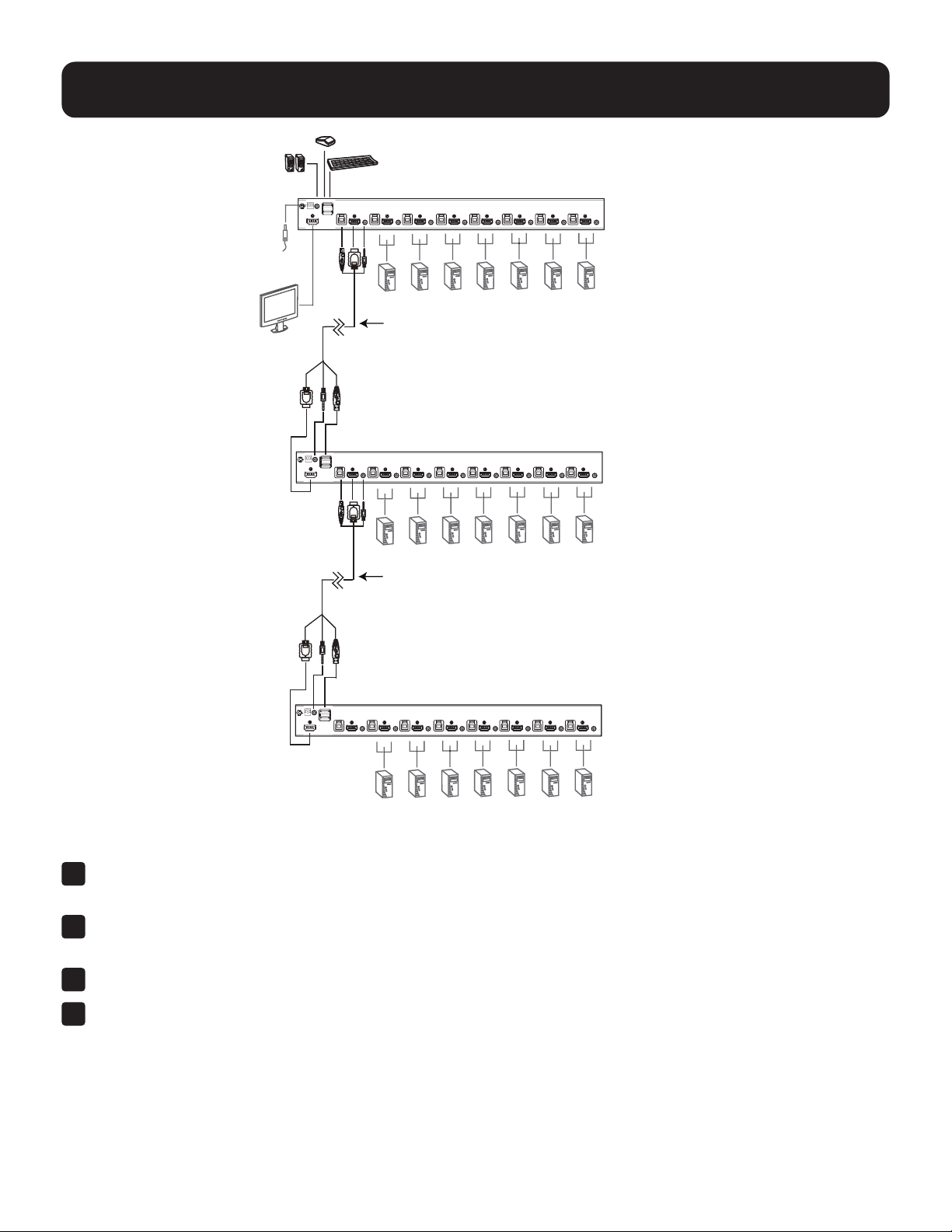
7.3.3 Three-Stage Cascade Installation
The procedures for setting up a three-stage installation are essentially the same as for a two-stage installation. Using
the B024-H4U08 in a three-stage setup, as many as 512 computers can be controlled in a complete installation. A table
showing the relation between the number of computers and the number of switches needed to control them can be
found in section 14.1 B024-H4U08 and B024-H4U16 Connection Tables.
Notes:
• The B024-H4U08 cannot be cascaded beyond the third level and the B024-H4U16 cannot cascaded beyond the second level.
• The B024-H4U08 can only be cascaded with other B024-H4U08 units. The B024-H4U16 can only be cascaded with other
B024-H4U16 units.
19
7. Installation
USB HDMI
KVM Cable Set
USB HDMI
KVM Cable Set
Onceyouhavenishedcablingup(seesection7.3.2 Two-Stage Cascade Installation), power up according to the
following sequence:
1
For each Third-Stage unit, plug the power adapter cable into the switch’s Power Jack, then plug the power adapter
into an AC source.
2
For each Second-Stage unit, plug the power adapter cable into the switch’s Power Jack, then plug the power
adapter into an AC source.
3
Plug the First-Stage unit’s power adapter cable into its Power Jack, then plug the power adapter into an AC source.
4
Power on the computers.
Notes:
• The Power On sequence requires that all Third-Stage units be powered on rst. After they are all on, the Second-Stage units must
be powered on next. After the Second-Stage units are on, the First-Stage units must be powered on last. Only after all the switches
have been powered on in this sequence, can the computers be powered on.
• The USB 3.0 hub cannot be accessed through the switch by computers on the second or third level of a cascaded installation.
• Make sure the computers and devices that the B024-H4U08 / B024-H4U16 connects to are also properly grounded.
20
7. Installation
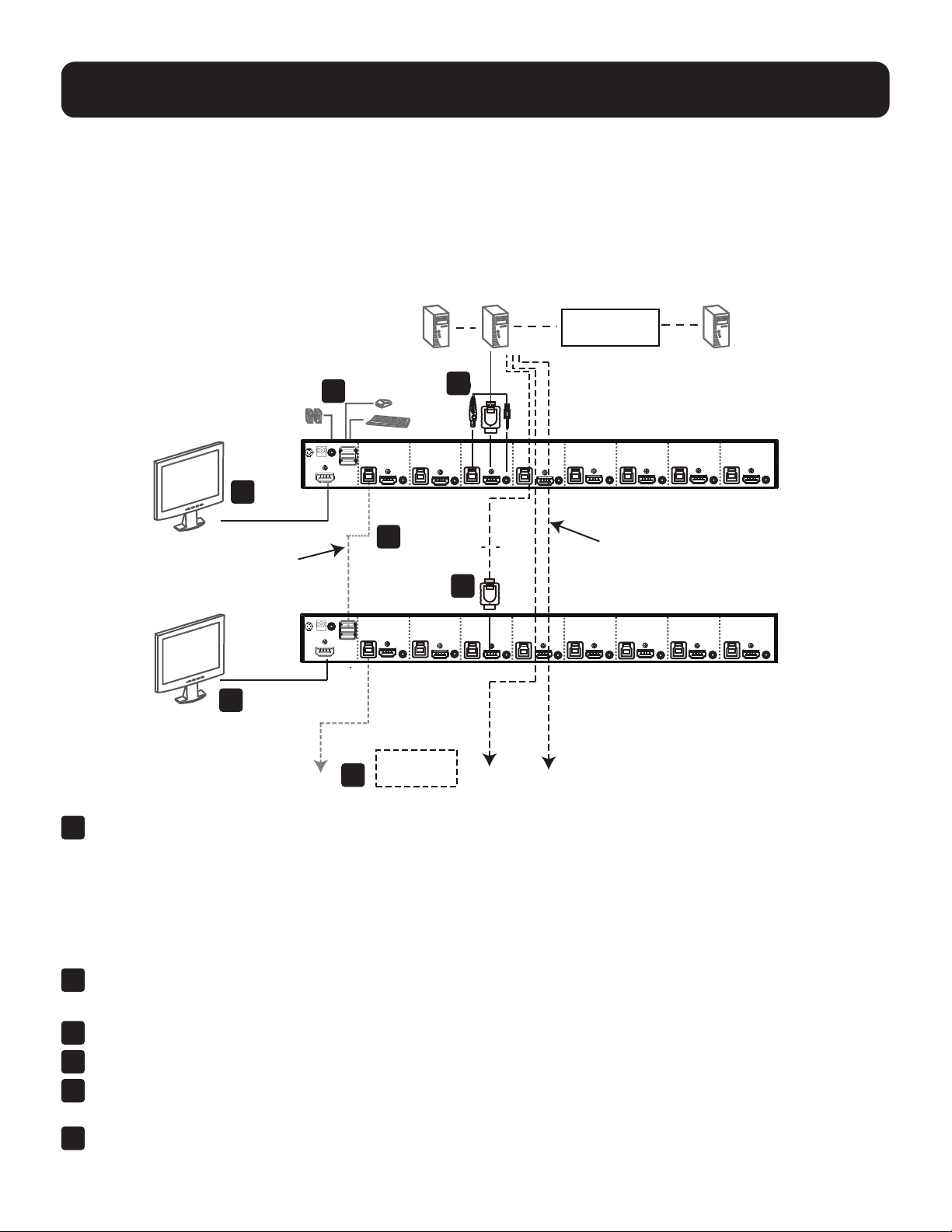
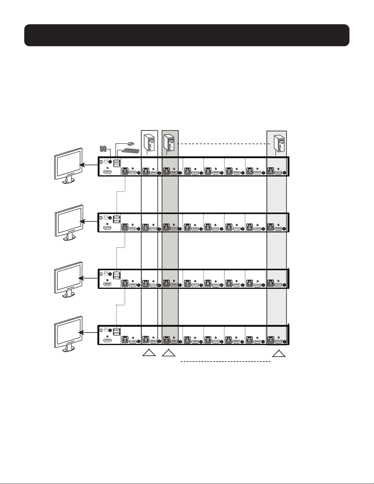
7.3.4 Multi-Display Installation
The B024-H4U08 and B024-H4U16 multi-display feature allows you to stack up to 8 units in a dual/triple/quad-display/
multi-displayinstallationtocontroluptoseven(B024-H4U08)orfteen(B024-H4U16)computersatonce.This
installationrequiresslightlydierentcablingthanthestandardcascadeandoersanextralevelofswitchingexibilityfor
multiple-monitor installations where each computer is equipped with multiple video cards.
Note: In a multi-display installation, the B024-H4U08 can only be connected to B024-H4U08 units, and the B024-H4U16 can only be
connected to B024-H4U16 units.
5
Computers with
2/3/4 video inputs
First Switch
5
HDMI cables
5
1
USB Type B to
Type A cable
Second Switch
3
Third / Fourth
Stage Units
4
2
1
Use a standard USB Type-A to USB Type-B cable to connect the Port 8 USB Type-B port on the First-Stage unit to
the USB Type-A port in the Console Ports Section of the second switch.
Notes:
• Port 8 is reserved to connect the units in a multi-display installation. Up to seven (B024-H4U08) or fteen (B024-H4U16)
computers can be attached, using KVM ports 1–7 (B024-H4U08) or ports 1–7/9–16 (B024-H4U08).
• Plug the USB Type-A connector into the lower USB (keyboard) Port in the Console Port Section. Both USB Ports are marked
with a similar icon to remind you of the correct USB port.
2
Use HDMI cables to connect the KVM’s DisplayPort on the second unit to the second video-in port on the computers.
Note: Only DisplayPort video cables are necessary–all other ports in the KVM section are not required in this installation.
3
Connect a display to the console section of the second switch.
4
Repeat steps 1-3 for any additional units for a total of up to a total of 8 switches.
5
Connectthecablesfortherstswitch(seesection7.3.1 Single-Stage Installation for details). All video, audio and
peripheraldevicesmustbeconnectedtotherstswitch.
6
PoweruptheKVMunits,startingwiththerstswitch,thenpoweronthecomputers.
Note: Make sure the computers and devices connected to the KVMs are also properly grounded.
5
5
1
5
2
3
4
21
7. Installation
7.3.5 Grouping Ports into Vertical Channels
Once the cables have been connected and multi-display mode has been selected in the OSD, the KVM will auto-detect
the channels and display modes. Users can then assign them a channel number as the port name so all the Port 1s
become Channel 1, all the Port 2s become Channel 2, ... , and all the Port 7s become Channel 7. The ports will all be
switched at the same time, channel by channel.
Dependingonthenumberofstagesinyourstack,theKVMinstallationoersdualdisplay(twostages),tripledisplay
(three stages), quad display (four stages) or multi-display (up to 8 stages) scenarios. For reference purposes, the
example below shows a four-stage installation with quad display functionality.
Ch1
Ch7 Ch6
First
Switch
Second
Switch
Third
Switch
Fourth
Switch

22
8. Basic Operation
8.1 Hot Plugging
The B024-H4U08 and B024-H4U16 KVMs support hot-plugging where components can be removed and added back
into the installation by unplugging their cables from the ports without needing to shut the unit down. In order for hot
plugging to work properly, the procedures described below must be followed:
8.1.1 Hot Plugging KVM Ports
InorderfortheOSDmenustocorrespondtoKVMportchanges,youmustmanuallyreconguretheOSDtoreectthe
new port information (see 9.6.3 F3: Set and 9.6.4 F4: Admin for details).
Note: If the computer’s operating system does not support hot plugging, this function may not work properly.
8.1.2 Hot Plugging Console Ports
The keyboard, monitor and mouse can all be hot plugged. When hot plugging the mouse:
• You may unplug and re-plug the mouse (e.g. to reset the mouse), as long the same mouse is used.
•Ifplugginginadierentmouse,allcomputersontheinstallationmustbeshutdownfor10seconds,thenrestarted
following the power up sequence described under Steps 6, 7, and 8 in section 7.3.2 Two-Stage Cascade Installation.
Note: If after hot-plugging there is no response to keyboard and/or mouse input, perform a Keyboard and Mouse Reset by
simultaneously pressing the 1 and 2 front panel pushbuttons.
8.2 Port Selection
The KVMs provide four port-selection methods to access the computers in the installation: Manual, an OSD
(on-screen display) menu system, Hotkeys, and RS-232 commands.
• For OSD (on-screen display), see section 9. OSD Operation for more information.
• For Hotkeys operation, see section 10. Hotkey Operation for more information.
• For RS-232 commands, see section 12. RS-232 Operation for more information.
Manual Port Switching
Use the front panel pushbutton switches to manually switch to a port.
8.3 Port ID Numbering
Each port on the KVM installation is assigned a unique Port ID. You can directly access any computer on any level of
the installation by specifying the Port ID that the computer is connected to–either with the OSD (see 9. OSD Operation),
or with the Hotkey port selection method (see 10. Hotkey Operation).
• A computer attached to a primary unit has a two-digit Port ID (from 01–08 for the B024-H4U08, or 01–16 for the
B024-H4U16) that corresponds to the KVM port number it is connected to.
• A computer attached to a secondary unit has a four-digit Port ID.
ThersttwodigitsrepresenttheKVMportnumberontheprimaryunitandthesecondtwodigitsrepresenttheKVM
port number on the secondary unit the computer is connected to. For example, a Port ID of 02 to 08 would refer to a
computer connected to KVM port 8 of a secondary unit that links back to KVM port 2 of the primary unit.

23
8. Basic Operation
8.4 Powering Off and Restarting the KVM
IfitbecomesnecessarytopoweroaKVMswitch,dothefollowingbeforerestartingit:
1
Unplug the KVM from its power source.
2
Shut down all computers that are attached to it.
Note: Unplug the power cords of any computers that have the Keyboard Power On function. Otherwise, the KVM will continue to
receive power from the computers.
3
Wait 10 seconds, then plug the KVM back into its power source.
4
Power on the computers.
Note: If there are stations cascaded down from the primary KVM, all the cascaded stations and the computers attached to them must
be shut down as well.

24
9. OSD Operation
The on-screen display (OSD) is a mouse- and keyboard-enabled, menu-driven method to handle computer control
and switching operations. All procedures start from the OSD main screen.
9.1 OSD Login
The OSD incorporates a two-level (administrator/user) password system. Before the OSD main screen displays, a
login screen appears requiring a password. Use the default username and password: administrator / password to
login.Onceyouhaveloggedinforthersttime,youwillbeaskedtochangethepasswordforsecuritypurposes.
Please follow the on-screen instructions to set your new password. The OSD main screen displays in administrator
mode. In this mode, you have administrator privileges with access to all administrator and user functions, and can
set up operations (including password authorization) as desired. If the password function has been set, you must
provide an appropriate administrator/user password in order to access the OSD.
9.2 OSD Hotkey
You can display the OSD on the console monitor while also viewing the display of any port on the KVM by pressing
the [Scroll Lock] key twice.
Note: You can optionally change the OSD hotkey to the Ctrl key, in which case you would press [Ctrl] twice (see 9.2 OSD
Hotkey). With this method, you must press the same [Ctrl] key.
25
9. OSD Operation
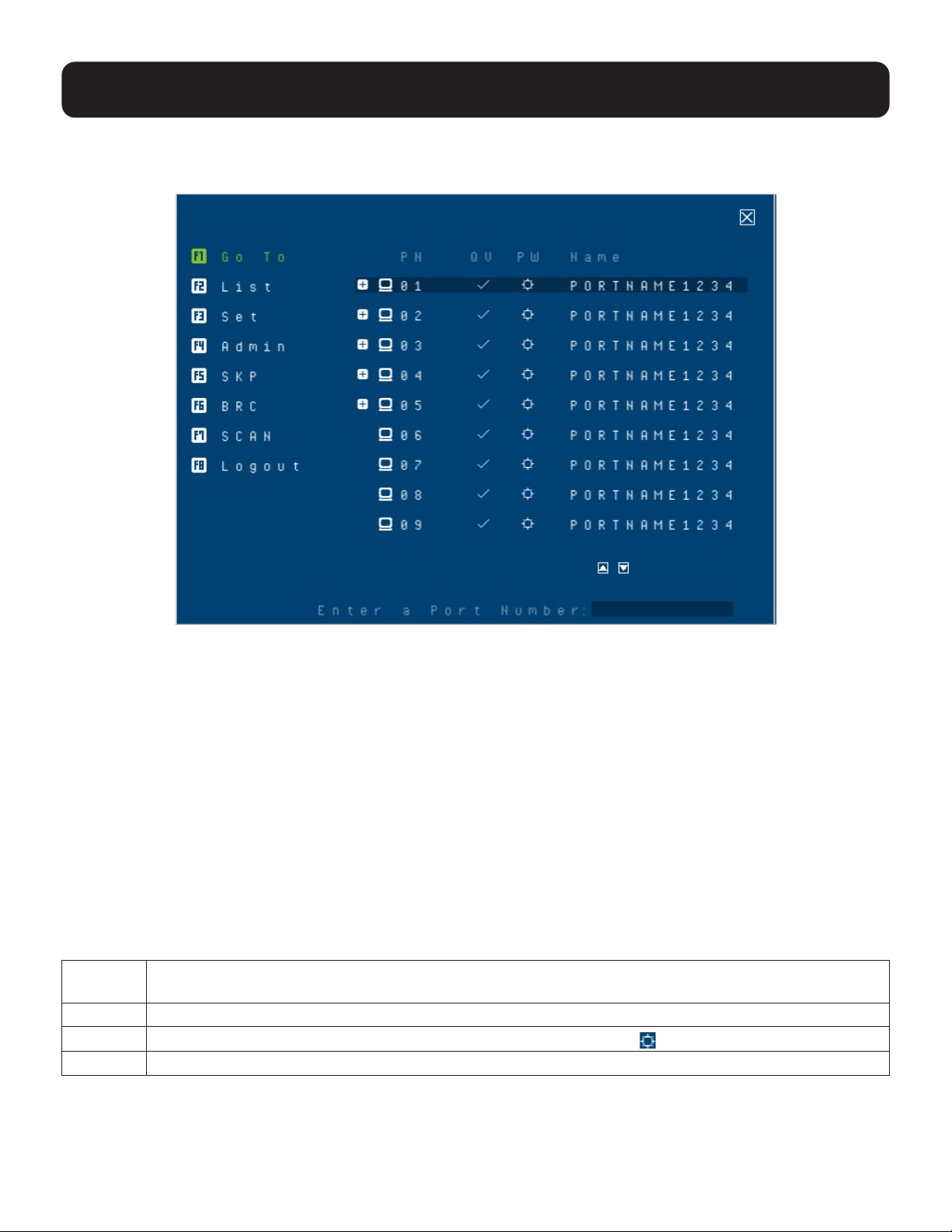
9.3 OSD Main Screen
When you invoke the OSD, a screen similar to the one below appears:
Notes:
• The diagram depicts the administrator’s main screen. The user main screen does not show the F4 and F6 functions, since these
are reserved for the administrator and cannot be accessed by users.
• The OSD always starts in list view, with the highlight bar at the same position it was in the last time it was closed.
• Only the ports that have been set accessible by the administrator for the current logged in user are visible.
• Enable Mouse Emulation to operate the OSD using the mouse. When the Mouse Emulation is disabled, you can only operate the
OSD using the keyboard.
• To enable the Mouse Emulation via OSD, refer to “Mouse Emulation” in the table in section 9.6.4 F4: Admin for details.
• To enable the Mouse Emulation via hotkeys, see section 10.14 Mouse Emulation Control.
• If the port list is collapsed, click on a switch number or move the highlight bar to it, then press the [Enter] key to expand the list.
Similarly, to collapse a switch’s port list, click on the switch number or move the highlight bar to it, then press the [Enter] key to
collapse the list.
9.4 OSD Main Screen Headings
PN This column lists the port ID numbers for all the KVM ports on the installation. The simplest method to
access a particular computer is to move the highlight bar to it, then press [Enter].
QV Ifaporthasselectedforquickviewscanning,acheckmark(√)displaysinthiscolumn.
PW
The computers that are powered on and are online have a sun symbol
in this column.
NAME If a port has been given a name, its name appears in this column.
26
9. OSD Operation
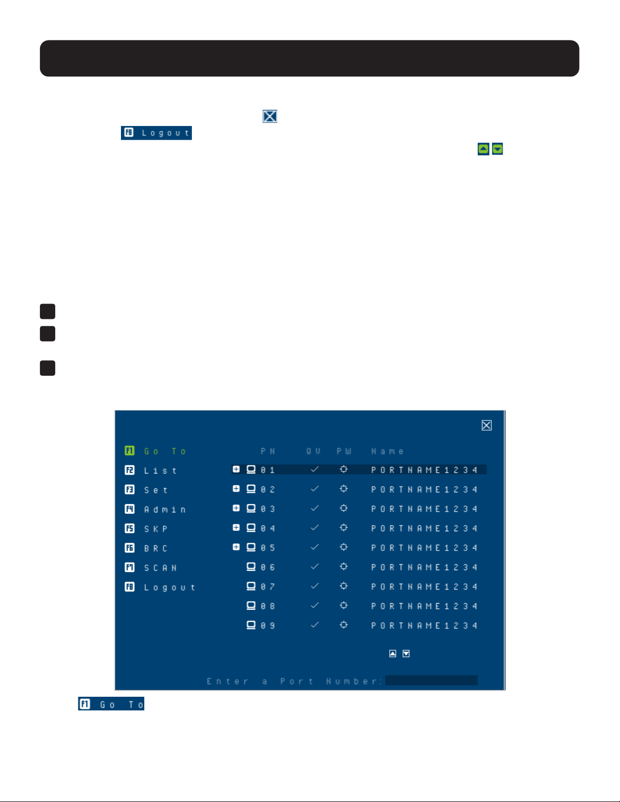
9.5 OSD Navigation
• To dismiss the menu and deactivate OSD, click at the upper right corner of the OSD window or press [Esc].
• To log out, click
at the left of the main screen, or press [F8].
• To move up or down through the list one screen at a time, click the up and down arrow symbols or use the
[Pg Up] and [Pg Dn] keys. If there are more list entries than what can appear on the main screen, the screen will scroll.
• To activate a port, click it or move the highlight bar to it, then press [Enter].
• After executing any action, you automatically return to the menu one level above.
9.6 OSD Functions
OSDfunctionsareusedtocongureandcontroltheOSD.Forexample,youcanrapidlyswitchtoanyport,scan
selected ports, limit the list you wish to view, designate a port as a quick view port, create or edit a port name, or make
OSD setting adjustments.
To access an OSD function:
1
Eitherclickonthefunctionkeyeldontheleftofthemainscreenorpressafunctionkeyonthekeyboard.
2
In the submenus that appear, make your choice either by clicking it or moving the highlight bar to it and pressing
[Enter].
3
Press [Esc] to return to the previous menu level.
9.6.1 F1: Go To
Clicking or pressing [F1] activates the Go To function. Go To allows you to switch directly to a port by
keying in the port’s ID. Enable mouse emulation for this function to work.
• To use the search method, key in the Port ID then press [Enter] to switch KVM, audio and USB focus, or [Spacebar]
to switch KVM and audio only.
27
9. OSD Operation
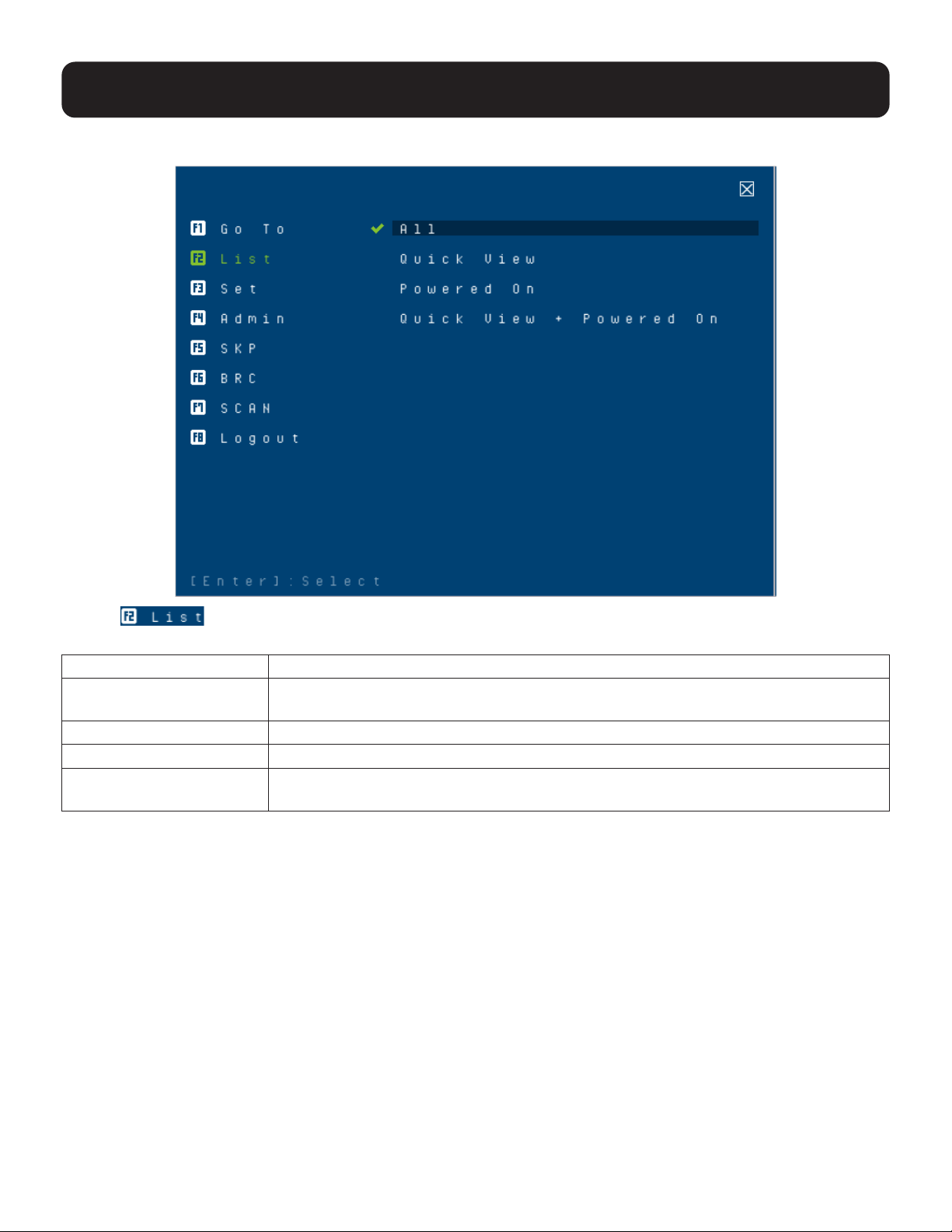
9.6.2 F2: List
Clicking or pressing [F2] activates the List function. This function lets you broaden or narrow the scope of
which ports the OSD displays on the main screen. The submenu choices and their meanings are provided in the table below.
Choice Meaning
ALL Lists all ports in the installation that have been set accessible by the administrator for
the current logged in user.
Quick View Lists only the ports that have been selected as quick view ports.
Powered On Lists only the ports that have their attached computers powered on.
Quick View + Powered On Lists only the ports that have been selected as quick view ports and that have their
attached computers powered on.
Movethehighlightbartothechoiceyouwant,thenpress[Enter].Acheckmark(√)appearsbeforethechoiceto
indicate that it is the currently selected one.
28
9. OSD Operation
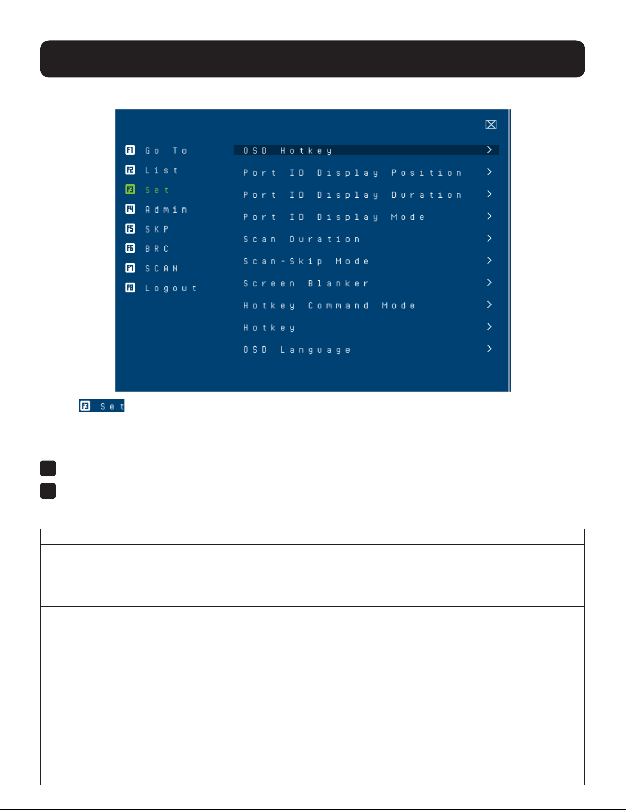
9.6.3 F3: Set
Clicking or pressing [F3] activates the Set function. This function allows the administrator and each user to
setuptheirownworkingenvironment.AseparateproleforeachisstoredbytheOSDandisactivatedaccordingtothe
username that was provided during login.
To change a setting:
1
Click it or move the highlight bar to it, then press [Enter].
2
After you select an item, a submenu with further choices appears. To make a selection, either click it or move the
highlightbartoit,thenpress[Enter].Acheckmark(√)appearsbeforetheselectedchoicetoindicatewhichoneitis.
The settings are explained in the following table:
Setting Function
OSD Hotkey Selects which hotkey activates the OSD function:
[Scroll Lock] [Scroll Lock] or [Ctrl] [Ctrl].
Sincethe[Ctrl]keycombinationmayconictwithprogramsrunningonthecomputers,
the default is the [Scroll Lock] combination.
Port ID Display Position Allows each user to customize the position where the port ID appears on the screen.
The default is the upper left corner, but users can choose to have it appear anywhere on
the screen.
Use the mouse or the arrow keys plus Pg Up, Pg Dn, Home, and End (on the numeric
keypadwithNumLocko).Arrowkeysmovethepositiononespaceatatime.PgUp
and Pg Dn brings the position to the top or bottom. Home and End brings the position to
the rightmost and leftmost of the screen. To position the port ID display, single-click or
press [Enter] to lock the position and return to the Set submenu.
Port ID Display Duration Determines how long a port ID displays on the monitor after a port change has taken
place.Thechoicesare:3Seconds(default)andAlwaysO.
Port ID Display Mode Selects how the port ID is displayed:
The port number plus the port name (Port Number + Port Name) (default), the port
number alone (Port Number) or the port name alone (Port Name).

29
9. OSD Operation
Setting Function
Scan Duration Determines how long the focus dwells on each port as it cycles through the selected
ports in Auto Scan mode (see 9.6.7 F7: Scan). Key in a value from 1 to 255 seconds,
then press [Enter].
Default is 5 seconds; a setting of 0 disables the SCAN function.
Note: We recommend to set the scan duration to 10 seconds.
Scan/Skip Mode Selects which computers will be accessed under skip mode (see 9.6.5 F5: SKP), and
Auto Scan mode (see 9.6.7 F7: Scan). Choices are:
ALL - All the ports which have been set accessible.
QUICK VIEW - Only those ports which have been set accessible and have been
selected as quick view ports.
POWERED ON - Only those ports which have been set accessible and are powered on.
QUICK VIEW + POWERED ON - Only those ports which have been set accessible and
have been selected as quick view ports and are powered on. The default is ALL.
Note: The quick view choices only appear on the administrator’s screen, since only the
adminstrator has Quick View setting rights.
Screen Blanker If there is no input from the console for the amount of time set with this function, the
screen is blanked. Key in a value from 1 to 30 minutes, then press [Enter]. The default
setting of 0 disables this function. The screen will be blanked in the amount of time set
(counting from the moment when OSD is closed).
Hotkey Command Mode Enables/disablesthehotkeycommandfunctionincaseaconictwithprograms
running on the computers occurs.
Hotkey Sets the keyboard shortcut for invoking Hotkey Mode (see 10.2 Hotkey Setting Mode).
Choices are: [NUM LOCK] + [-] (minus) (default), and [CTRL] + [F12].
OSD Language Sets the language used in the OSD. Choices are: English (Default), German, Japanese,
SimpliedChinese,TraditionalChinese,Spanish,FrenchandRussian.
30
9. OSD Operation
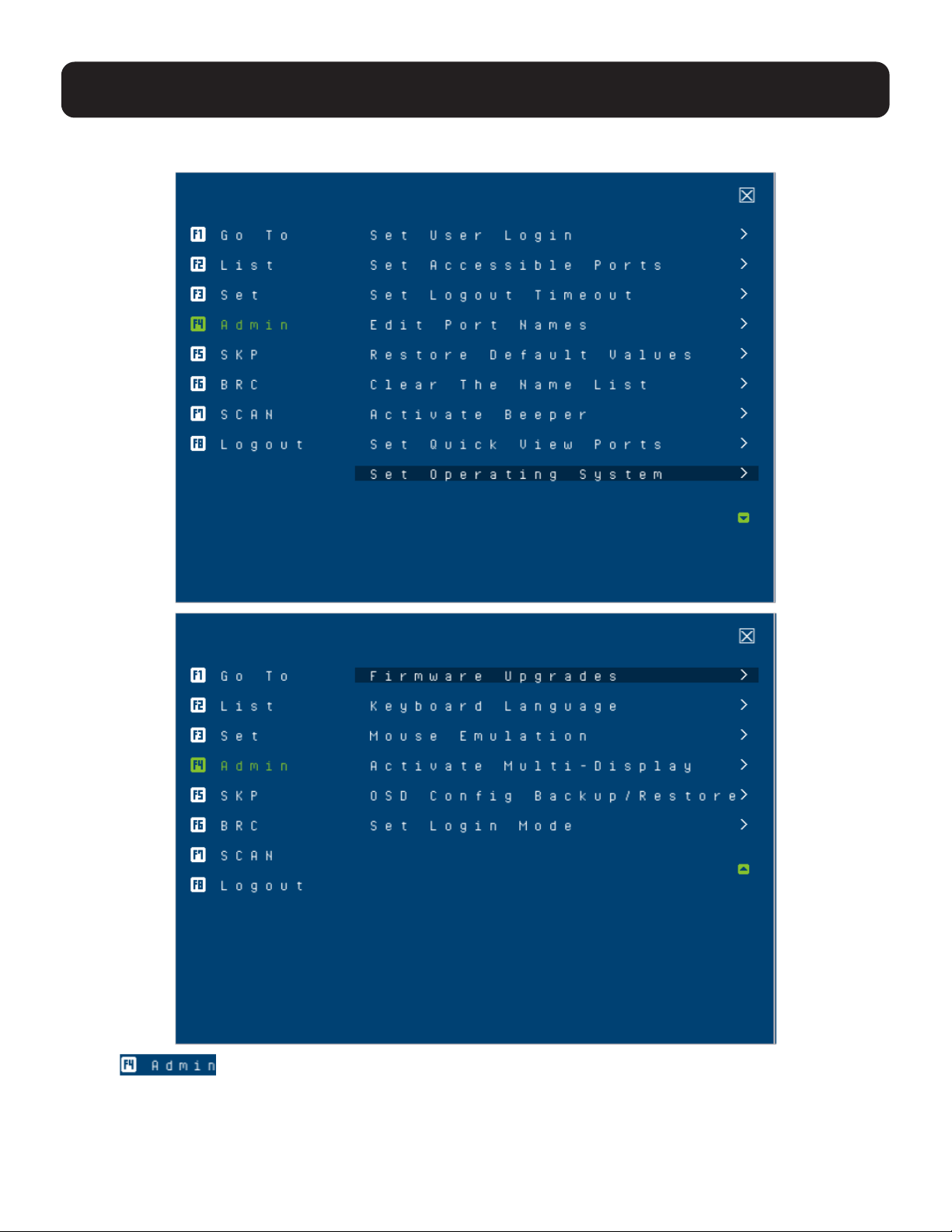
9.6.4 F4: Admin
Clicking or pressing [F4] activates Admin function. F4 is an administrator-only function. It allows the
administratortocongureandcontroltheoveralloperationoftheOSD.Tochangeasetting,clickonthesettingsitem
youwanttocongure,orusetheupanddownarrowkeystomovethehighlightbartoitandpress[Enter].
After you select an item, a submenu with further choices appears. Click an item, or move the highlight bar to it then
press[Enter].Acheckmark(√)appearsbeforetheselecteditemsothatyouknowwhichoneitis.Thesettingsare
explained in the following table:

31
9. OSD Operation
Setting Function
Set User Login This function is used to set usernames and passwords for the administrator and users:
1. Usernames and passwords for one administrator and four users can be set.
2. Afteryouselecttheadministratoreldoroneoftheuserelds,aeldthatallowsyou
to key in the username and password appears. Usernames and passwords can be
from 1 to 16 characters long and can consist of any combination of letters and numbers
(A–Z, 0–9) and some additional keys (* ( ) + : - , ?. / space).
3. Foreachindividual,keyintheusernameandpassword,conrmthepassword,choose
SAVE, then press [Enter].
4. To modify or delete a previous username and/or password, use the backspace key to
erase individual letters or numbers. Press [Enter] when done.
Note: Usernames and passwords are not case sensitive. Usernames are displayed in capital letters
in the OSD.
Set Accessible Ports Thisfunctionallowstheadministratortodeneuseraccesstothecomputersonthe
installation on a port-by-port basis.
For each user, select the target port, then press the [Spacebar] to cycle through the
choices: F (full access), V (view only) or blank. Repeat until all access rights have been
set, then press [Enter]. The default is F for all users on all ports.
Notes:
• A blank setting means that no access rights are granted. The port will not show up on the user’s
LIST on the main screen.
• The administrator always has full access to all ports.
Set Logout Timeout If there is no input from the console for the amount of time set with this function, the user
is automatically logged out. A login is necessary before the console can be used again.
This enables other users to gain access to the computers when the original user is no
longer accessing them, but has forgotten to log out. To set the timeout value, key in a
number from 1 to 180 minutes, then press [Enter]. The default setting of 0 disables this
function.
Note: This feature does not function if Set Login Mode is disabled.
Edit Port Names To help remember which computer is attached to a particular port, every port can be given
a name. This function allows the administrator to create, modify, or delete port names.
To edit a port name:
1. Click the port or use the navigation keys to move the highlight bar to it.
2. Key in the new port name or modify/delete the old one. The maximum number of
characters allowed for the port name is 12.
Legal characters include:
• All alpha characters: A–Z
• All numeric characters: 0–9
• * ( ) + : - , ? . /
Case does not matter. The OSD displays the port name in all capitals, no matter how
they are keyed in.
3. Whenyouhavenishedediting,press[Enter]tohavethechangetakeeect.Toabort
the change, press [Esc].
Restore Default Values This function is used to undo all changes and return the setup to the original factory default
settings (see 14.4 Factory Default Hotkeys and Settings), except for the port name list,
username and password information, which are saved.
Clear The Name List This function clears the port name list.
Activate Beeper ChoicesareY(on),orN(o).Whenactivated,thebeepersoundswheneveraportis
changed, when activating the Auto Scan function (see 9.6.7 F7: Scan) or an invalid entry
is made on an OSD menu. The default is Y.

32
9. OSD Operation
Setting Function
Set Quick View Ports This function lets the administrator select which ports to include as quick view ports.
• To select/deselect a port as a quick view port, use the navigation keys to move the
highlight bar to it and press [Spacebar].
•Whenaporthasbeenselectedasaquickviewport,acheckmark(√)displaysinthe
QV column of the LIST on the main screen. When a port is deselected, the check mark
(√)disappears.
• If one of the quick view options is chosen for the LIST view (see 9.6.2 F2: List), only a
port that has been selected here will display on the list.
• If one of the quick view options is chosen for auto-scanning, only a port that has been
selected here will be auto-scanned.
The default has no ports selected for quick view.
Set Operating System Thisfunctionallowstheadministratortodenetheoperatingsystemforthecomputer
connected to each KVM port. The default setting is Win (PC compatible).
To set the port operating system:
1. From the list, select the port for which you wish to set the computer’s operating system.
2. Set the operating system by pressing [Spacebar] to cycle through Win, MAC, SUN,
or Other.
3. Press [Esc] to exit. The operating system you selected is assigned to the KVM port.
Firmware Upgrade InordertoupgradeKVM’s,youmustrstenableFirmwareUpgrademodewiththissetting.
Whenyoubringupthismenu,thecurrentrmwareversionlevelsaredisplayed.SelectY
to enable Firmware Upgrade mode, or select [Esc] to leave this menu without enabling it.
Keyboard Language Sets the language for the computer keyboard attached to the KVM port. To select a
keyboard language, single-click it or use the navigation keys to move the highlight bar to
it and press [Enter].
Choices are: Auto (default), (US) English, (UK) English, German (Deutch), German
(Swiss), French, Hungarian, Italian, Japanese, Korean, Russian, Spanish, Swedish,
TraditionalChinese,andSimpliedChinese.
Mouse Emulation Enables / disables the mouse emulation function.
Note: This function is supported in the rst level of an installation only. Enable mouse emulation to
perform any independent switching of a port and for Auto Scan Mode or Skip Mode to work.
Activate Multi-Display Enables multi-display mode for dual, triple, quad, or multi-display mode in multiple-monitor
installations,whereeachcomputeristtedwithmultiplevideocards(see7.3.4 Multi-
Display Installation for details).
Note: Multi-display mode must be enabled on the OSD before the cables are connected.
OSDCongBack/
Restore
EntersOSDCongurationBackup/Restoremode.TheFirmwareManagementUtility
letsyoubackupthecurrentOSDcongurationoftheKVMswitchandrestoreitwhen
necessary.StoringtheOSDcongurationsettingsisusefulwhendeployingmorethan
one installation that uses the same settings (see 13.7OSDCongurationBackup/
Restore for details).
Set Login Mode This function allows the administrator to request users to log in or not. When the login
dialog box is disabled, the system disables the login/logout function. If the system is
re-started, the login/logout function remains disabled.
33
9. OSD Operation
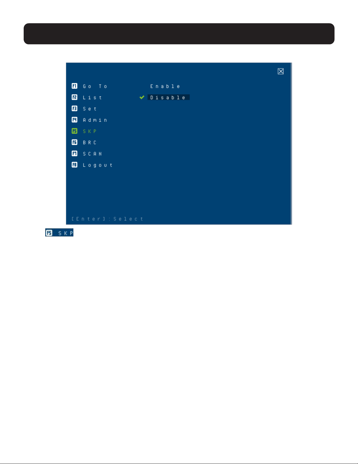
9.6.5 F5: SKP
Clicking or pressing [F5] invokes Skip (SKP) mode. This function lets you easily skip backward or forward
and switch the console focus from the currently active computer port to the previous or next accessible one.
Note: Mouse emulation must be enabled for Skip mode to work.
• The selection of computers available for skip mode switching is made with the Scan–Skip mode setting under the F3:
SET function (see 9.6.3 F3: Set for details).
• When you are in skip mode:
Press[←]toskiptothepreviousaccessibleportonthelist.
Press[→]toskiptothenextaccessibleportonthelist.
Press[↑]toskiptothepreviousaccessibleport.Ifthepreviousaccessibleporthascascadedaswitch,thenitskips
to the last accessible port of that switch.
Press[↓]toskiptothenextaccessibleport.Ifthenextaccessibleporthascascadedaswitch,thenitskipstotherst
accessible port of that switch
Note: When skipping, you will only skip to the previous or next accessible computer that is in the Scan/Skip mode selection (refer
to Scan/Skip mode in the table in section 9.6.3 F3: Set for details).
•IfaporthasbeenselectedforScan/Skipmode,whenthefocusswitchestothatport,asetof[↑],[↓],[←],[→]
symbols appear before its port ID displays.
•Whileskipmodeisineect,theconsolewillnotfunctionnormally.Youmustexitskipmodeinordertoregaincontrol
of the console.
• To exit skip mode, press [Spacebar] or [Esc].
34
9. OSD Operation
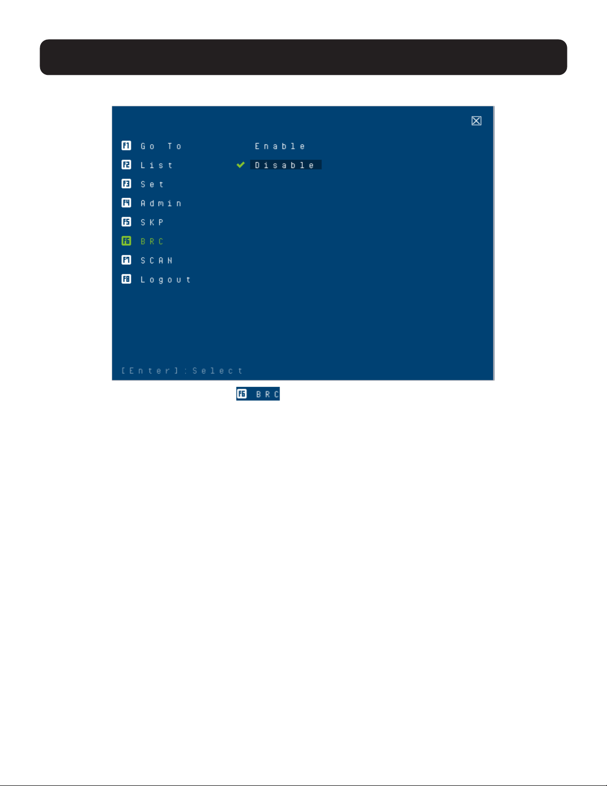
9.6.6 F6: BRC
F6 is an administrator-only function. Clicking or pressing [F6] invokes Broadcast (BRC) mode. When this
functionisineect,commandssentfromtheconsolearebroadcasttoallavailablecomputersontheinstallation.
This function is particularly useful for operations that need to be performed on multiple computers, such as performing
a systemwide shutdown, installing or upgrading software, etc
.
WhileBRCmodeisineect:
• A speaker symbol appears before the port ID display of the port that currently has the console focus.
• The mouse will not function normally. You must exit BRC mode in order to regain control of the mouse.
To exit BRC mode:
•InvoketheOSD(withtheOSDhotkey),thenclicktheF6eldorpress[F6]toturnBRCmodeo.
•WhenBRCmodeisineect,theScrollLockLEDashes.Itstopsashingandrevertstonormalstatuswhenyou
exit BRC.

35
9.6.7 F7: Scan
Clicking or pressing [F7] invokes Auto Scan mode. This function allows you to automatically switch among the available
computers at regular intervals so that their activity can be monitored without the inconvenience of switching yourself.
Note: Mouse emulation must be enabled for Auto Scan to work.
• The selection of computers to be included for auto-scanning is made with the Scan/Skip mode setting under the F3:
SET function (refer to Scan/Skip mode in the table in section 9.6.3 F3: Set for details).
• The amount of time that each port displays is set with the Scan Duration setting under the F3: SET function (refer to
Scan Duration in the table in section 9.6.3 F3: Set for details). To stop at a particular location, press the [Spacebar] to
stop scanning.
•Ifthescanningstopsonanemptyportoronewherethecomputerisattachedbutispoweredo,themonitorscreen
willbeblankandthemouseandkeyboardwillhavenoeect.AftertheScanDurationtimeisup,thescanfunctionwill
move on to the next port.
• As each computer is accessed, an S appears in front of the port ID display to indicate it is being accessed under Auto
Scan mode. When the port ID with the symbol displays, the background screen is blank.
•WhileAutoScanmodeisineect,theconsolewillnotfunctionnormally.YoumustexitAutoScanmodeinorderto
regain control of the console.
• While you are in Auto Scan mode, you can pause the scanning in order to keep the focus on a particular computer,
either by pressing P or with a left click of the mouse.
• To exit Auto Scan mode, press the [Spacebar] or [Esc].
9. OSD Operation
36
9. OSD Operation
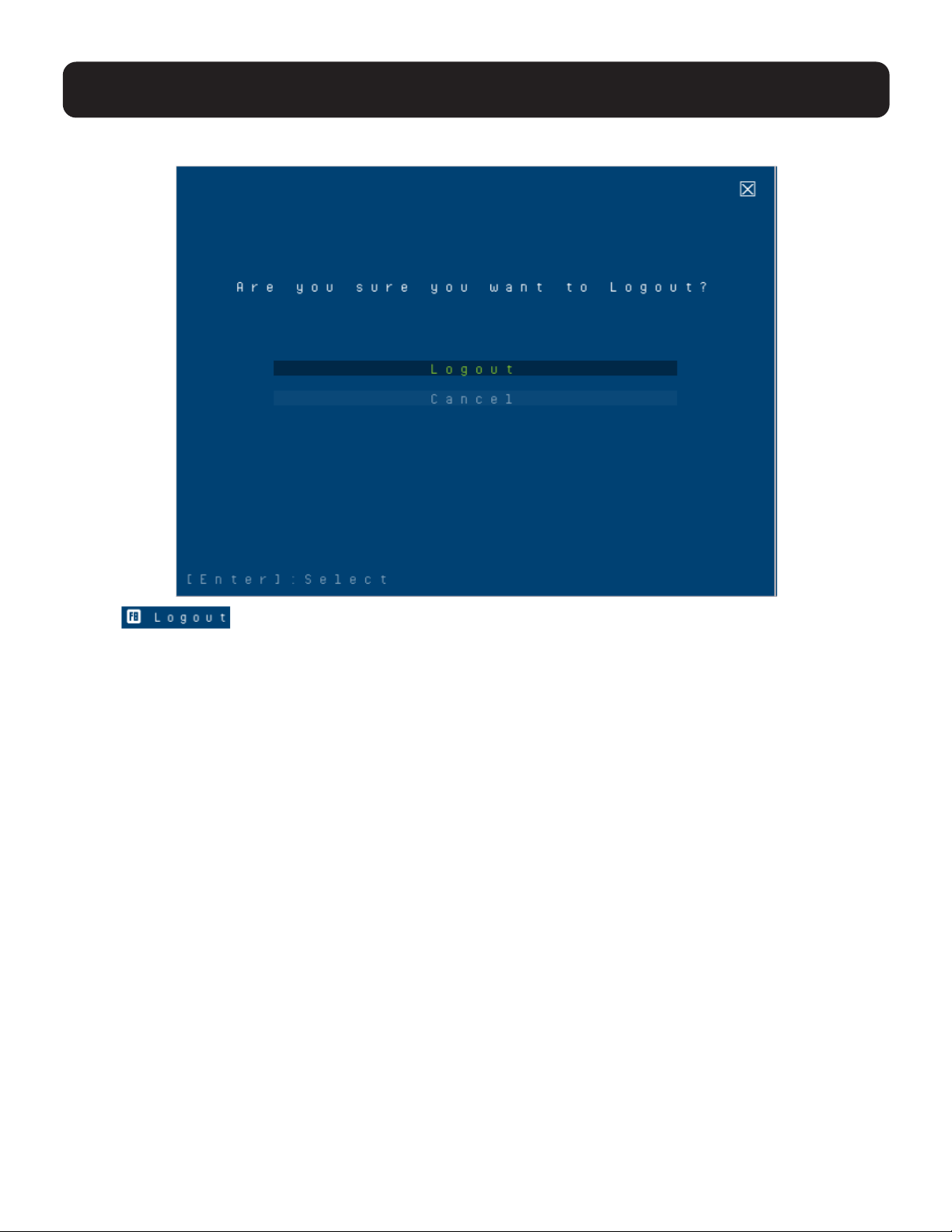
9.6.8 F8: Logout
Clicking or pressing [F8] logs you out of OSD control of the computers and blanks the console screen.
Thisisdierentfromsimplypressing[Esc]whenyouareatthemainscreentodeactivatetheOSD.Withthisfunction
you must log in all over again to regain access to the OSD, whereas with [Esc], all you have to do to reenter the OSD
is tap the OSD hotkey.
Notes:
• When you reenter the OSD after logging out, the screen stays blank except for the OSD main screen. You must input your
username and password before you can continue.
• If you reenter the OSD after logging out and immediately use [Esc] to deactivate the OSD without having selected a port from the
OSD menu, a NULL PORT message displays on the screen. The OSD hotkey will bring up the main OSD screen.

37
10. Hotkey Operation
10.1 Hotkey Port Control
Hotkey port control allows you to provide KVM focus to a particular computer directly from the keyboard.
The B024-H4U08 and B024-H4U16 provides the following hotkey port control features:
• Selecting the Active Port
• Auto Scan Mode Switching
• Skip Mode Switching
• Computer Keyboard / Mouse Reset
• Enable / Disable Mouse Emulation
The following settings can also be controlled in Hotkey Setting Mode (HSM):
• Setting the Beeper
• Setting the HSM Hotkey
• Setting the OSD Hotkey
• Setting the Port Operating System
• Restoring the OSD Default Values
• Setting the EDID Mode
• Setting the Video DynaSync Mode
Notes:
• Mouse emulation must be enabled to perform independent switching of a port and for Auto Scan Mode or Skip Mode to work.
• To enable the Mouse Emulation via OSD, refer to “Mouse Emulation” in the table in section 9.6.4 F4: Admin for details.
• To enable the Mouse Emulation via hotkeys, see section 10.14 Mouse Emulation Control.
10.2 Hotkey Setting Mode (HSM)
HotkeySettingModeisusedtosetupyourKVMswitchconguration.AlloperationsbeginwithinvokingHotkey
Setting Mode (HSM).
Invoking HSM
To invoke HSM:
1
Press and hold down [Num Lock].
2
Press and release [-].
3
Release [Num Lock].
or
1
Hold down the [Ctrl] key.
2
Press and release the [F12] key.
3
Release the [Ctrl] key.
When HSM is active:
• A command line appears on the monitor screen. The command line prompt is the word HOTKEY in white text on a
blue background and displays the subsequent hotkey information that you key in.
• Ordinary keyboard and mouse functions are suspended – only hotkey-compliant keystrokes (described in the
sections that follow), can be input.
• Pressing [Esc] exits HSM.

38
10. Hotkey Operation
10.3 Select the Active Port
Each KVM port is assigned a port ID (see section 8.3 Port ID Numbering). You can directly access any computer on
theinstallationwithahotkeycombinationthatspeciestheportIDoftheKVMportthatacomputerisconnectedto.To
access a computer using hotkeys:
1
Invoke HSM with the [Num Lock] + [-] or [Ctrl] + [F12] combination.
2
Key in the port ID. The port ID numbers display on the command line as you key them in. If you make a mistake,
use [Backspace] to erase the wrong number.
3
Press [Enter]. After you press [Enter], the KVM focus switches to the designated computer and you automatically
exit HSM.
Note: In HSM, KVM focus will not switch to a port if an invalid switch or port number is entered. The hotkey command line will
continue to display on the screen until you enter a valid switch and port number combination, or exit HSM.
Hotkey Action
[PN] [Enter] Brings the KVM, USB hub and audio focus to the computer attached to the port
correspondingtothespeciedPortID.
[PN] [K] [Enter] BringsonlytheKVMandaudiofocustothecomputerattachedtothespeciedport.TheUSB
hub and audio focus remain where they are.
[PN] [U] [Enter] BringsonlytheUSBhubfocustothecomputerattachedtothespeciedport.TheKVMand
audio focus remain where they are.
Note: The [PN] stands for the computer’s Port ID number (1, 2, 3, or 4) (see section 8.3 Port ID Numbering for details). Replace the
[PN] with the appropriate Port ID when entering Hotkey combinations.
10.4 Auto Scan Mode
Auto Scan automatically switches at regular intervals among all the KVM ports that have been set as accessible under
Scan–Skip Mode so their activity can be monitored automatically (refer to Scan/Skip mode in the table in section 9.6.3
F3: Set for details).
Invoking Auto Scan
To start Auto Scan, key in the following Hotkey combination:
1
Enable mouse emulation. To enable the Mouse Emulation via OSD, refer to “Mouse Emulation” in the table
in section 9.6.4 F4: Admin for details. To enable the Mouse Emulation via hotkeys, see section 10.14 Mouse
Emulation Control.
2
Invoke HSM with the [Num Lock] + [-] or [Ctrl] + [F12] combination.
3
Press [A]. After you press A, then press [Enter]. You will automatically exit HSM and enter Auto Scan mode.
• While in Auto Scan mode, you can pause the scanning in order to keep the focus on a particular computer either
by pressing P or with a left click of the mouse. During the time that auto-scanning is paused, the command line will
display: AUTO SCAN: PAUSED.
Pausing when you want to keep the focus on a particular computer is more convenient than exiting Auto Scan
modebecausewhenyouresumescanning,youstartfromwhereyoulefto.Ifontheotherhand,youexitedand
restarted,scanningwouldstartoverfromtheveryrstcomputerontheinstallation.
ToresumeAutoScanning,pressanykeyorleftclick.Scanningcontinuesfromwhereitlefto.
•WhileAutoScanmodeisineect,ordinarykeyboardandmousefunctionsaresuspended–onlyAutoScanmode
compliant keystrokes and mouse clicks can be input. You must exit Auto Scan mode in order to regain normal
control of the console.
4
To exit Auto Scan mode, press [Esc] or [Spacebar]. Auto-scanning stops when you exit Auto Scan mode.
Note: Enable mouse emulation to perform any independent switching of a port and for Auto Scan Mode or Skip Mode to work (see
section 10.14 Mouse Emulation Control).

39
10. Hotkey Operation
10.5 Skip Mode
This feature allows you to switch between computers in order to monitor them manually. You can dwell on a particular
portforaslongasyoulike–asopposedtoauto-scanning,whichautomaticallyswitchesafteraxedinterval.
To invoke Skip mode, key in the following hotkey combination:
1
Enable mouse emulation (see 10.13 Mouse Emulation Control).
2
Invoke HSM with the [Num Lock] + [-] or [Ctrl] + [F12] combination.
3
Keyin[↑],[↓],[←],or[→].
• After you press an arrow key, you automatically exit HSM and enter Skip mode where you can switch ports as
follows:
← Skips to the previous accessible port (see Scan/Skip mode in the table in section 9.6.3 F3: Set for details
for information regarding accessible ports.)
→ Skips to the next accessible port.
↑ Skips to the previous accessible port. If the previous accessible port has cascaded a switch, then it skips to
the last accessible port of that switch.
↓ Skipstothenextaccessibleport.Ifthenextaccessibleporthascascadedaswitch,thenitskipstotherst
accessible port of that switch.
• Once you are in Skip mode, you can continue skipping by pressing the arrow keys. You do not need to use the
[Num Lock] + [-] combination again.
•WhileSkipmodeisineect,ordinarykeyboardandmousefunctionsaresuspended–onlySkipmodecompliant
keystrokes can be input. You must exit Skip mode in order to regain normal control of the console.
4
To exit Skip mode, press [Esc] or [Spacebar].
Note: Enable mouse emulation to perform any independent switching of a port and for Auto Scan Mode or Skip Mode to work (see
10.14 Mouse Emulation Control).
10.6 Keyboard / Mouse Reset
If the keyboard or mouse cease to function on the computer connected to the currently selected port, you can perform
a keyboard / mouse reset on the computer. This function is essentially the same as unplugging and replugging the
keyboard and mouse on the target computer. To perform a computer keyboard / mouse reset, key in the following hotkey
combination:
1
Invoke HSM with the [Num Lock] + [-] or [Ctrl] + [F12] combination.
2
Press [F5].
After you press [F5] you automatically exit HSM and regain keyboard and mouse control on the computer connected
to the KVM port. If you fail to regain keyboard / mouse control on the computer after pressing [F5], perform a console
keyboard and mouse reset.
10.7 Hotkey Beeper Control
The beeper (see “Activate Beeper” in the table in section 9.6.4 F4: Admin)canbehotkeytoggledonando.Thedefault
setting is enabled. To toggle the beeper, key in the following hotkey combination:
1
Invoke HSM with the [Num Lock] + [-] or [Ctrl] + [F12] combination.
2
Press [B].
Afteryoupress[B],thebeepertogglesonoro.ThecommandlinedisplaysBEEPERONorBEEPEROFFforone
second, then disappears and you will automatically exit HSM.

40
10. Hotkey Operation
10.8 HSM Hotkey Control
The HSM Hotkey (see “Hotkey” in the table in section 9.6.3 F3: Set) can be toggled between [Num Lock] + [-], and [Ctrl]
+ [F12]. To toggle the HSM Hotkey:
1
Invoke HSM with the [Num Lock] + [-] or [Ctrl] + [F12] combination.
2
Press [H].
After you press [H], the command line displays HOTKEY HAS BEEN CHANGED for one second, then disappears and
you will automatically exit HSM.
10.9 OSD Hotkey Control
The OSD Hotkey (see “OSD Hotkey” in the table in section 9.6.3 F3: Set) can be toggled between [Scroll Lock], [Scroll
Lock] and [Ctrl], [Ctrl]. To toggle the OSD Hotkey, key in the following hotkey combination:
1
Invoke HSM with the [Num Lock] + [-] or [Ctrl] + [F12] combination.
2
Press [T].
After you press [T], the command line displays HOTKEY HAS BEEN CHANGED for one second, then disappears and
you will automatically exit HSM.
10.10 Port OS Control
A port’s operating system can be changed to match that of the computer attached to the port. To change a port’s
operating system, key in the following hotkey combination:
1
Invoke HSM with the [Num Lock] + [-] or [Ctrl] + [F12] combination.
2
Key in [F1], [F2], or [F3], the Function of [F1], [F2], and [F3] keys is listed in the following table:
Key Description
F1 Sets the Port OS to Windows
F2 Sets the Port OS to Mac
F3 Sets the Port OS to Sun
After pressing a function key, you will automatically exit HSM.
10.11 Restore Default Values
This administrator-only hotkey restores the KVM’s default values (see 14.4 Factory Default Hotkeys and Settings). To
restore the default values, key in the following hotkey combination:
1
Invoke HSM with the [Num Lock] + [-] or [Ctrl] + [F12] combination.
2
Press [R].
3
Press [Enter].
After you press [Enter], the command line displays RESET TO DEFAULT SETTING for one second, then disappears
and you will automatically exit HSM.
41
10. Hotkey Operation
10.12 EDID Mode
TocongureanEDIDmodefortheKVM:
1
Invoke HSM with the [Num Lock] + [-] or [Ctrl] + [F12] combination.
2
Press [V].
3
Key in [1], [2], [3], or [4]. The Function of [1], [2], [3], and [4] keys is listed in the following table:
Key Description
1 Sets the switch to read DisplayPort monitor’s EDID (Default)
2 Default monitor’s EDID 1920 x 1080 @ 60 Hz
4
Press [Enter]. After pressing [Enter], you will automatically exit HSM.
10.13 Mouse Emulation Control
The default setting is enabled. To disable:
1
Invoke HSM with the [Num Lock] + [-] or [Ctrl] + [F12] combination.
2
Press [M].
This procedure is a toggle. Repeat to enable.
Note: Enable mouse emulation to perform any independent switching of a port and for Auto Scan Mode or Skip Mode to work.
10.14 HSM Summary Table
After invoking HSM (see 10.2 Hotkey Setting Mode), key in one of the following keys to perform the corresponding function:
Key Function
[PN] [Enter] Switches KVM, audio and USB focus directly to the computer that corresponds to that port ID
(PN = port number).
[PN] [K] [Enter] Switches KVM and audio focus directly to the computer that corresponds to that port ID
(PN = port number).
[PN] [U] [Enter]
Switches USB focus only directly to the computer that corresponds to that port ID (PN = port number).
Note: This hotkey functions on the rst level of an installation only.
[A] [Enter] Starts Auto Scan. The KVM focus cycles from port to port at the default 5-second intervals.
[A] [n] [Enter] Starts Auto Scan at n-second intervals (n = 0–255 seconds).
Note: When n=0, the Auto Scan will not be activated.
[H] Toggles between the default ([Num Lock] [-]) and alternate ([Ctrl] [F12]) HSM invocation keys.
[T] Toggles between the default ([Scroll Lock] [Scroll Lock]) and alternate ([Ctrl] [Ctrl]) OSD Hotkey.
[F1] Sets the port OS to Windows.
[F2] Sets the port OS to Mac.
[F3] Sets the port OS to Sun.
[F5] Performs a keyboard / mouse reset on the target computer.
[B] Enables/disables the beeper.
[R] [Enter]
Resets the hotkey settings to their default status (see 14.4 Factory Default Hotkeys and Settings).
[D] Invokes Video DynaSync, an exclusive technology that eliminates boot-up display problems and
optimizes resolution when switching between ports.

42
10. Hotkey Operation
Key Function
[V] [n] [Enter] Sets EDID Mode.
• n = 1, read DisplayPort monitor’s EDID.
• n = 2, default EDID mode (full HD 1920 x 1080 @ 60 Hz.
[P] [n] [Enter] Sets the KVM switching mode.
n = 1, sets the KVM to Normal Switching Mode.
n = 2, sets the KVM to Fast Switching Mode.
Note: This hotkey is only supported by B024-H4U08 / B024-H4U16 using rmware version v1.1.102
or later.
[M] Enables/disables mouse emulation.
[←] Skips to the previous computer on the list while in Skip mode.
[→] Skips to the next computer on the list while in Skip mode.
[↑] Skips to the previous accessible port. If the previous accessible port has cascaded a switch, it skips
to the last accessible port of that switch.
[↓] Skips to the next accessible port. If the next accessible port has cascaded a switch, it skips to the
rstaccessibleportofthatswitch.
[ESC] or
[Spacebar]
Exits hotkey setting mode (HSM).
Note: Enable mouse emulation to perform any independent switching of a port and for Auto Scan Mode or Skip Mode to work (see
10.14 Mouse Emulation Control).
43
11. Keyboard Emulation
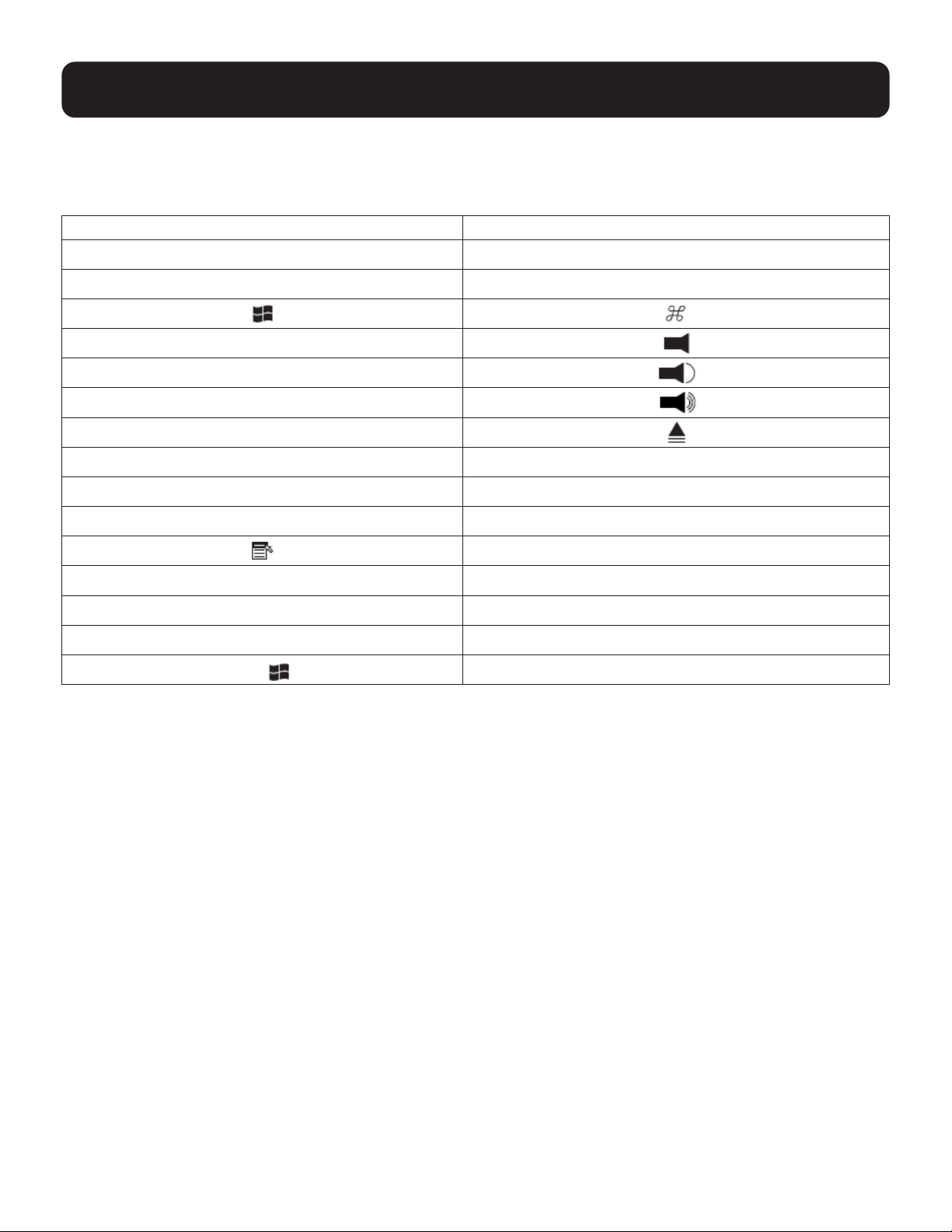
11.1 Mac Keyboard
The PC-compatible (101/104 key) keyboard can emulate the functions of the Mac keyboard. The emulation mappings
are listed in the table below.
PC Keyboard Mac Keyboard
[Shift] Shift
[Ctrl] Ctrl
[Ctrl] [1]
[Ctrl] [2]
[Ctrl] [3]
[Ctrl] [4]
[Alt] Alt
[Print Screen] F13
[Scroll Lock] F14
=
[Enter] Return
[Backspace] Delete
[Insert] Help
[Ctrl]
F15
Note: When using key combinations, press and release the rst key [Ctrl], then press and release the activation key.
44
11. Keyboard Emulation
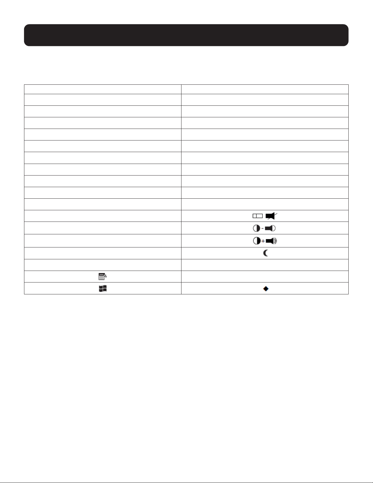
11.2 Sun Keyboard
The PC-compatible (101/104 key) keyboard can emulate the functions of the Sun keyboard when the Control key [Ctrl]
is used in conjunction with other keys. The corresponding functions are shown in the table below.
PC Keyboard Sun Keyboard
[Ctrl] [T] Stop
[Ctrl] [F2] Again
[Ctrl] [F3] Props
[Ctrl] [F4] Undo
[Ctrl] [F5] Front
[Ctrl] [F6] Copy
[Ctrl] [F7] Open
[Ctrl] [F8] Paste
[Ctrl] [F9] Find
[Ctrl] [F10] Cut
[Ctrl] [1]
[Ctrl] [2]
[Ctrl] [3]
[Ctrl] [4]
[Ctrl] [H] Help
Compose
Note: When using key combinations, press and release the rst key [Ctrl], then press and release the activation key.
45
12. RS-232 Operation
The KVM’s built-in bi-directional RS-232 serial interface allows system control through a high-end controller or PC.
RS-232 serial operations in the KVM installation are managed via HyperTerminal sessions on systems that are
runningWindows.InordertousethisfeaturetosendcommandstotheKVM,youmustrstdownloadandinstalla
HyperTerminal application.
12.1 Setup
Install a HyperTerminal application on a computer that is not part of the installation, which will be used to control the
switch via the RS-232 connection. HyperTerminal applications can be download from the Internet and many operating
systems are embedded with HyperTerminal applications.
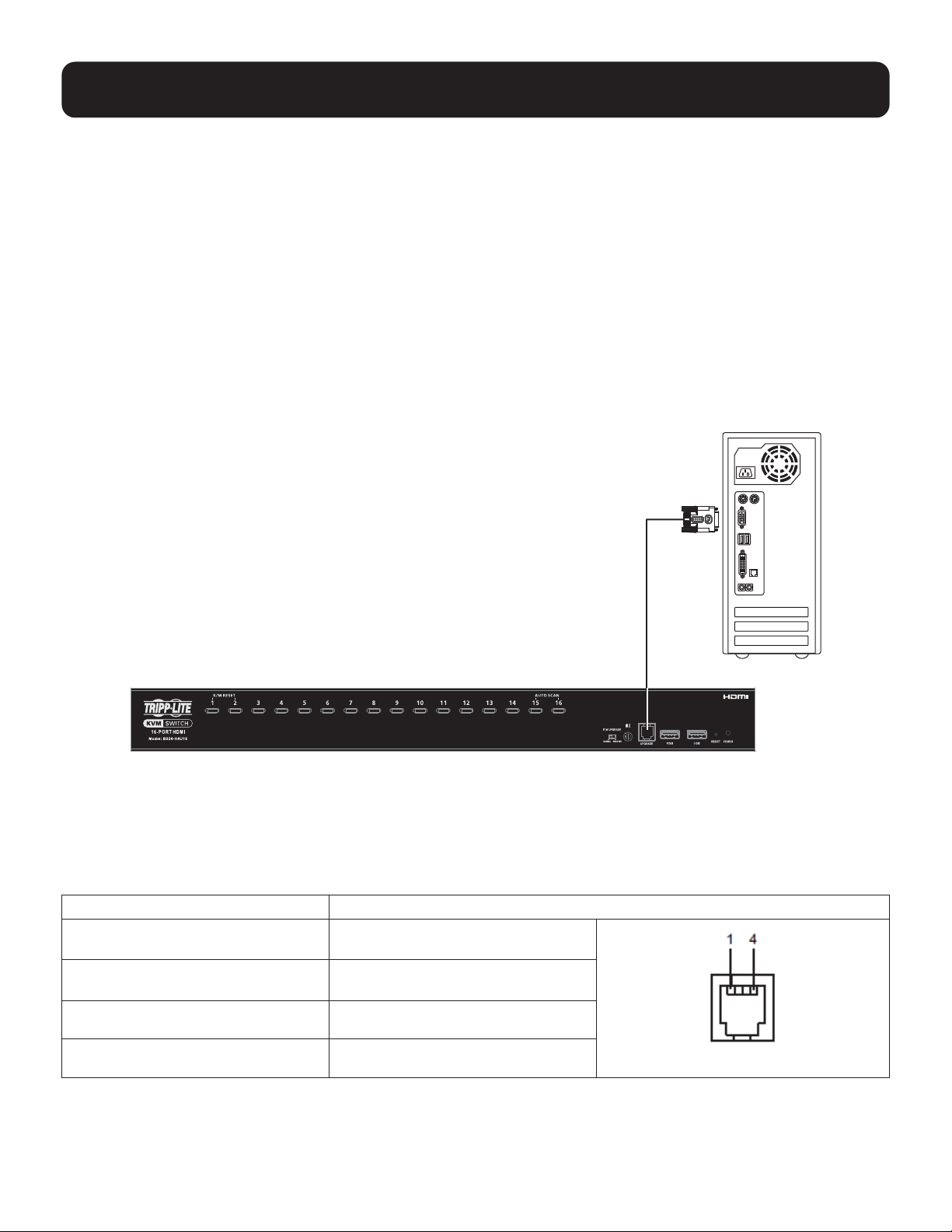
Hardware Connection
Use a the Firmware Upgrade Cable provided with this unit to connect a computer’s serial port to the Firmware Upgrade
Port on the KVM’s front panel, as shown in the diagram below:
Note: B024-H4U16 model shown. The port locations are the same for the B024-H4U08, except for the number of KVM ports.
12.2 RS-232 Pin Assignments
Pin assignments for the B024-H4U08 and B024-H4U16 KVM Firmware Upgrade Port are used for connecting to a serial
terminal.
Pin Assignment
1 TXD: Transmit Data
RJ11 Female
2 RXD: Receive Data
3 N/A
4 GND: Signal Ground
Firmware Upgrade Cable
46
12. RS-232 Operation
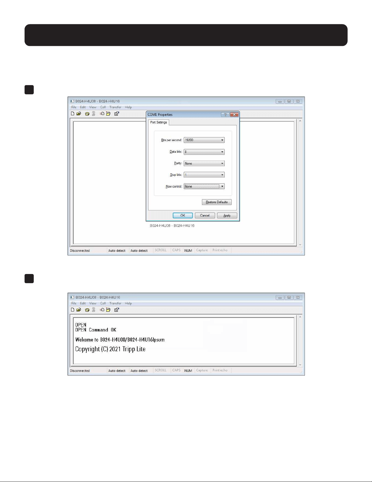
12.3 Console Login: HyperTerminal
Once a physical connection from the computer to the KVM switch has been made, you can establish a
HyperTerminal session.
1
Open the HyperTerminalapplication,conguretheportsettingsforCOM1port,thenclickOK.
Bits per Second: 19200, Data Bits: 8, Parity: None, Stop bits: 1, Flow Control: None.
2
Afterconguringtheportsettingsyoumustenableserialcontrolontheswitchbytypingthecommand:
Open + [Enter].

47
12. RS-232 Operation
12.4 RS-232 Commands
After you login via HyperTerminal (see 12.3 Console Login: HyperTerminal), use the instructions below to send
RS-232 commands to control the switch from the computer.
When RS-232 control is enabled via the Open + [Enter] command, the KVM’s front panel pushbuttons, OSD, hotkeys
and remote control commands will be disabled until the RS-232 control is disabled.
12.4.1 Verication
Afterenteringacommand,avericationmessageappearsattheendofthecommandline:
Response Message Description
Command OK Command or parameter is correct.
Command incorrect Command or parameter is incorrect.
With all commands in the sections that follow:
• Each command string can be separated with a space.
• The [Enter] command can be replaced with the ASCII code: 0x0D0A
12.4.2 Login
The Login command allows you to log in to the KVM and send RS-232 commands. When you log in, the RS-232 link is
“opened” and the KVM will not respond to front panel pushbuttons, hotkeys, OSD or remote control commands until the
RS-232 link is closed (see 12.4.6 Switch Port).
Use the Formula→tosetParameters→tocreateaCommand.
Formula
Command + Control + Name + Number + [Enter]
Parameters
Command Description
login Login command
Control Description
U Input user name + password
Name Description
xxxxxxxxxxxxx The login user name
Password Description
xxxxxxxxxxxxx The login user password
Enter Description
Enter Enter and send out command
Login Command
The formula for the Login command is as follows:
Command + Control + Name + Number + [Enter]
For example, to login via username and password, type the following:
login u administrator p12345 [Enter]
48
12. RS-232 Operation
12.4.3 Logout
The Logout commands allows you to log out of the KVM and close the RS-232 link.
Use the Formula→tosetParameters→tocreateaCommand.
Formula
Command + [Enter]
Parameters
Command Description
Logout Logout command
Enter Description
Enter Enter and send out command
Logout Command
The formula for the Logout command is as follows:
Command + [Enter]
For example, to logout of the KVM, type the following:
logout [Enter]
12.4.4 Open/Close RS-232 Link
The Open/Close RS-232 Link commands allow you to open and close the link between the computer sending RS-232
commands and the KVM. When the link is open, the KVM only accepts RS-232 commands and will not respond to front
panel pushbuttons, OSD, hotkeys and remote control commands until the link is closed. The link opens when you login
and closes after 2 minutes if no command is sent.
Use the Formula →tosetParameters→tocreateaCommand.
Formula
Command + [Enter]
Parameters
Command Description
Open Open RS-232 Link command
Close Close RS-232 Link command
Enter Description
Enter Enter and send out command
Open/Close RS-232 Link Commands
The available formulas for the Open/Close RS-232 Link commands are as follows:
1
Command + [Enter]
For example, to open the RS-232 link between the computer and KVM, type the following: open [Enter]
2
Command + [Enter]
For example, to close the RS-232 link between the computer and KVM, type the following: close [Enter]

49
12. RS-232 Operation
12.4.5 Set Baud Rate
TheSetBaudRatecommandallowsyoutocongurethebaudratesettingfortheserialportconnection.Thedefault
baud rate is 19200.
Use the Formula→tosetParameters→tocreateaCommand.
Formula
Command + Control + [Enter]
Parameters
Command Description
baud Baud rate command
Control Description
19200 Set baud rate to 19200 (Default)
38400 Set baud rate to 38400
9600 Set baud rate to 9600
Enter Description
Enter Enter and send out command
Set Baud Rate Commands
The available formulas for the Set Baud Rate commands are as follows:
1
Command + Control + [Enter]
For example, to set the baud rate to 19200, type the following:
baud 19200 [Enter]
2
Command + Control + [Enter]
For example, to set the baud rate to 38400, type the following:
baud 38400 [Enter]
12.4.6 Switch Port
The Switch Port command allows you to switch ports. The default port is 01.
Use the Formula→tosetParameters→tocreateaCommand.
Formula
Command + Control + [Enter]
Parameters
Command Description
sw Switch Port command
Control Description
ixx Input port number
xx= 01~08 (B024-H4U08); 01~16 (B024-H4U16)
Enter Description
Enter Enter and send out command

50
12. RS-232 Operation
Switch Port Command
The available formula for the Switch Port command is as follows:
Command + Control + [Enter]
For example, to switch to port 2, type the following:
sw i02 [Enter]
Note: The Control command can be skipped and the default value will be used.
12.4.7 Hotkey Setting
The Hotkey Setting command allows you to change the hotkey used to invoke the HSM (Hotkey Setting Mode).
The default hotkey is [Num Lock] + [-].
Use the Formula→tosetParameters→tocreateaCommand.
Formula
Command + Control + [Enter]
Parameters
Command Description
hotkey Hotkey Setting command
Control Description
num Change the HSM invoke key to:
[Num Lock] + [-] (Default)
f12 Change the HSM invoke key to:
[Ctrl] + [F12]
Enter Description
Enter Enter and send out command
Hotkey Setting Commands
The available formulas for Hotkey Setting commands are as follows:
1
Command + Control + [Enter]
For example, to change the HSM invoke key to [Num Lock] + [-], type the following:
hotkey num [Enter]
2
Command + Control + [Enter]
For example, to change the HSM invoke key to [Ctrl] + [F12], type the following:
hotkey f12 [Enter]

51
12.4.8 OSD Hotkey
The OSD Hotkey command allows you to change the hotkey used to invoke the OSD. The default hotkey is [Scroll][Scroll].
Use the Formula→tosetParameters→tocreateaCommand.
Formula
Command + Control + [Enter]
Parameters
Command Description
osdkey OSD Hotkey command
Control Description
scroll Change OSD hotkey invoke key to: [Scroll] [Scroll] (Default)
ctrl Change OSD hotkey invoke key to: [Ctrl] [Ctrl]
Enter Description
Enter Enter and send out command
Hotkey Switching Commands
The available formulas for OSD Hotkey commands are as follows:
1
Command + Control + [Enter]
For example, to change the OSD hotkey invoke key to [Scroll] [Scroll], type the following:
osdkey scroll [Enter]
2
Command + Control + [Enter]
For example, to change the OSD hotkey invoke key to [Ctrl] [Ctrl], type the following:
osdkey ctrl [Enter]
12.4.9 USB Reset
TheUSBResetcommandallowsyoutoresettheUSBconnection.ThedefaultUSBresetsettingiso.
Use the Formula→tosetParameters→tocreateaCommand.
Formula
Command + Control + [Enter]
Parameters
Command Description
usbreset USB Reset command
Control Description
on Enable USB reset connection
Enter Description
Enter Enter and send out command
12. RS-232 Operation

52
12. RS-232 Operation
USB Reset Command
The available formula for the USB Reset command is as follows:
Command + Control + [Enter]
For example, to reset the USB connection, type the following:
usbreset on [Enter]
12.4.10 Restore Default Settings
The Restore Default Settings command allows you to reset all of the KVM’s settings back to the default.
The default setting is OFF.
Use the Formula→tosetParameters→tocreateaCommand.
Formula
Command + Control + [Enter]
Parameters
Command Description
reset Restore Default Settings command
Control Description
on Enable restore default values
Enter Description
Enter Enter and send out command
Restore Default Value Command
The available formula for the Restore Default Settings command is as follows:
Command + Control + [Enter]
For example, to restore all KVM settings back to the default, type the following:
reset on [Enter]
12.4.11 Firmware Upgrade
TheFirmwareUpgradecommandallowsyoutoenablethermwareupgrademode.Thedefaultsettingiso.
Use the Formula→tosetParameters→tocreateaCommand.
Formula
Command + Control + [Enter]
Parameters
Command Description
upgrade Firmware Upgrade command
Control Description
on Enablermwareupgrademode
Enter Description
Enter Enter and send out command

53
12. RS-232 Operation
Firmware Upgrade Command
The available formula for the Firmware Upgrade command is as follows:
Command + Control + [Enter]
Forexample,toenablermwareupgrademode,typethefollowing:
upgrade on [Enter]
12.4.12 KVM Status
TheKVMStatuscommandallowsyoutodisplayread-onlyinformationabouttheKVM’scurrentcongurationstatus.
Thedefaultsettingiso.
Use the Formula→tosetParameters→tocreateaCommand.
Formula
Command + Control + [Enter]
Parameters
Command Description
status KVM Status command
Control Description
on Enable KVM status
Enter Description
Enter Enter and send out command
KVM Status Command
The available formula for the KVM Status command is as follows:
Command + Control + [Enter]
Forexample,todisplaythecongurationstatusfortheB024-H4U08/B024-H4U16,typethefollowing:
status on [Enter]
A message similar to the one below will then appear:
hotkey: [numlock]+[-] / [scrolllock],[scrolllock]
os setting: pc
keyboard emulation: enabled/disabled
keyboard layout: English
mouse emulation: enabled/disabled
monitor re-detection: enabled/disabled
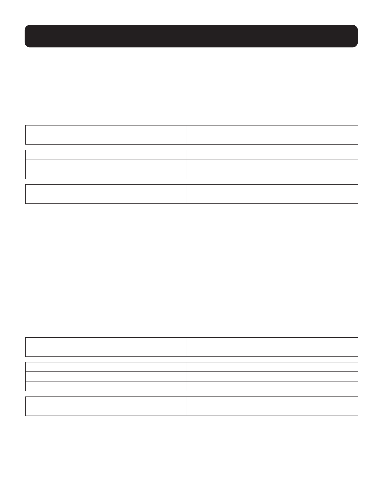
54
12. RS-232 Operation
12.4.13 EDID Mode
The EDID Mode command allows you to set EDID mode for the KVM.
Use the Formula→tosetParameters→tocreateaCommand.
Formula
Command + Control + [Enter]
Parameters
Command Description
edid Set EDID Mode command
Control Description
port1 Set to display A (DisplayPort monitor) EDID
default Set to default EDID
Enter Description
Enter Enter and send out command
EDID Mode Command
The available formula for the KVM Status command is as follows:
Command + Control + [Enter]
For example, to set the KVM’s EDID mode to default EDID, type the following:
edid default [Enter]
12.4.14 Broadcast Mode
TheBroadcastModecommandallowsyoutosetenable/disablebroadcastmodefortheKVM.Thedefaultsettingiso.
Use the Formula→tosetParameters→tocreateaCommand.
Formula
Command + Control + [Enter]
Parameters
Command Description
broadcast Set Broadcast Mode command
Control Description
on Enable broadcast mode for the KVM
o Disable broadcast mode for the KVM
Enter Description
Enter Enter and send out command
Broadcast Mode Command
The available formula for the KVM Status command is as follows:
Command + Control + [Enter]
For example, to enable the KVM’s broadcast mode, type the following:
broadcast on [Enter]
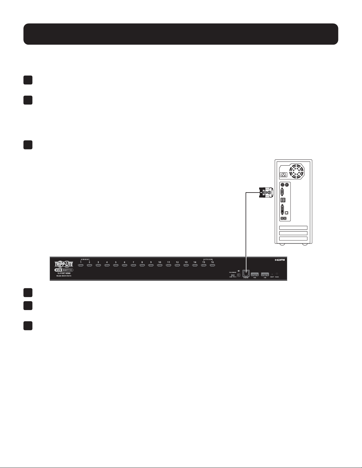
55
13. Firmware Management Utility
13.1 Downloading the Firmware
Todownloadthermware:
1
From a computer that is not part of your KVM installation, go to tripplite.com and choose the model name that
relatestoyourdevice.Alistofavailablermwareappears.
2
Choosethermwarethatyouwishtoinstall(usuallythemostrecent)anddownloadittoyourcomputer.
13.2 Preparation
Toprepareforthermwareupgrade,dothefollowing:
1
Use the Firmware Upgrade Cable provided with this unit to connect a COM port on your computer to the Firmware
Upgrade Port of your switch.
2
Shut down all computers on the KVM installation.
3
From your KVM switch console, login to the OSD as the administrator (see 9.1 OSD Login) and select the F4
Admin function.
4
Scroll down to Firmware Upgrades. Press [Enter], then press [Y] to invoke Firmware Upgrade mode (refer to
“Firmware Upgrade” in the table in section 9.6.4 F4: Admin for details).
Or
Invoke the Firmware Upgrade mode using RS-232 command (see 12.4.11 Firmware Upgrade).
Firmware Upgrade Cable
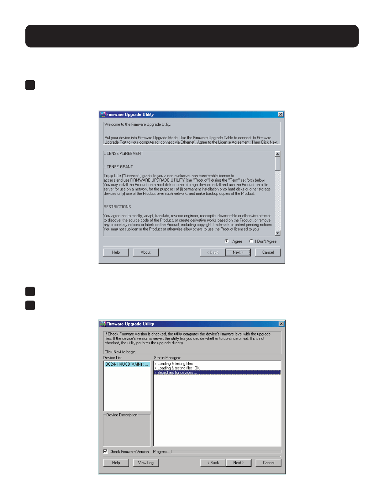
56
13. Firmware Management Utility
13.3 Starting the Upgrade
Toupgradethermware:
1
Runthedownloadedrmwareupgradepackagele,eitherbydoubleclickingtheleiconorbyopeninga
command line and entering the full path to it.
The Firmware Upgrade Utility welcome screen will appear:
Note: The screens shown in this section are for reference only. The wording and layout of the actual Firmware Upgrade Utility may
vary slightly from these examples.
2
Read the License Agreement and enable the “I Agree” radio button.
3
Click Next to continue. The Firmware Upgrade Utility main screen will appear. The devices capable of upgrades are
listed in the Device List panel:
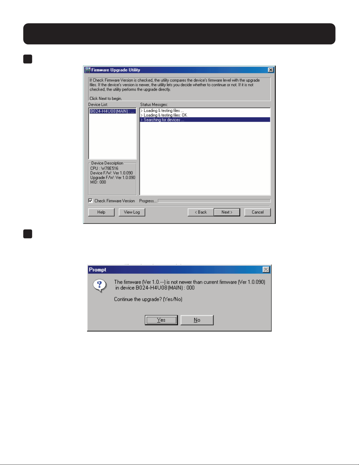
57
13. Firmware Management Utility
4
When selecting a device in the list, its description appears in the Device List panel.
5
Click Next to perform the upgrade.
IfyouenabledCheckFirmwareVersion,theUtilitycomparesthedevice’srmwarelevelwiththatoftheupgradeles.
Ifitndsthatthedevice’sversionishigherthantheupgradeversion,adialogboxwillappearinformingyouofthe
situationandoeringyoutheoptiontocontinueorcancel.
Ifyoudidn’tenableCheckFirmwareVersion,theUtilityinstallstheupgradeleswithoutcheckingwhethertheyarea
higher level or not.
As the upgrade proceeds, status messages appear in the Status Messages panel and the progress toward completion is
shown on the Progress bar.
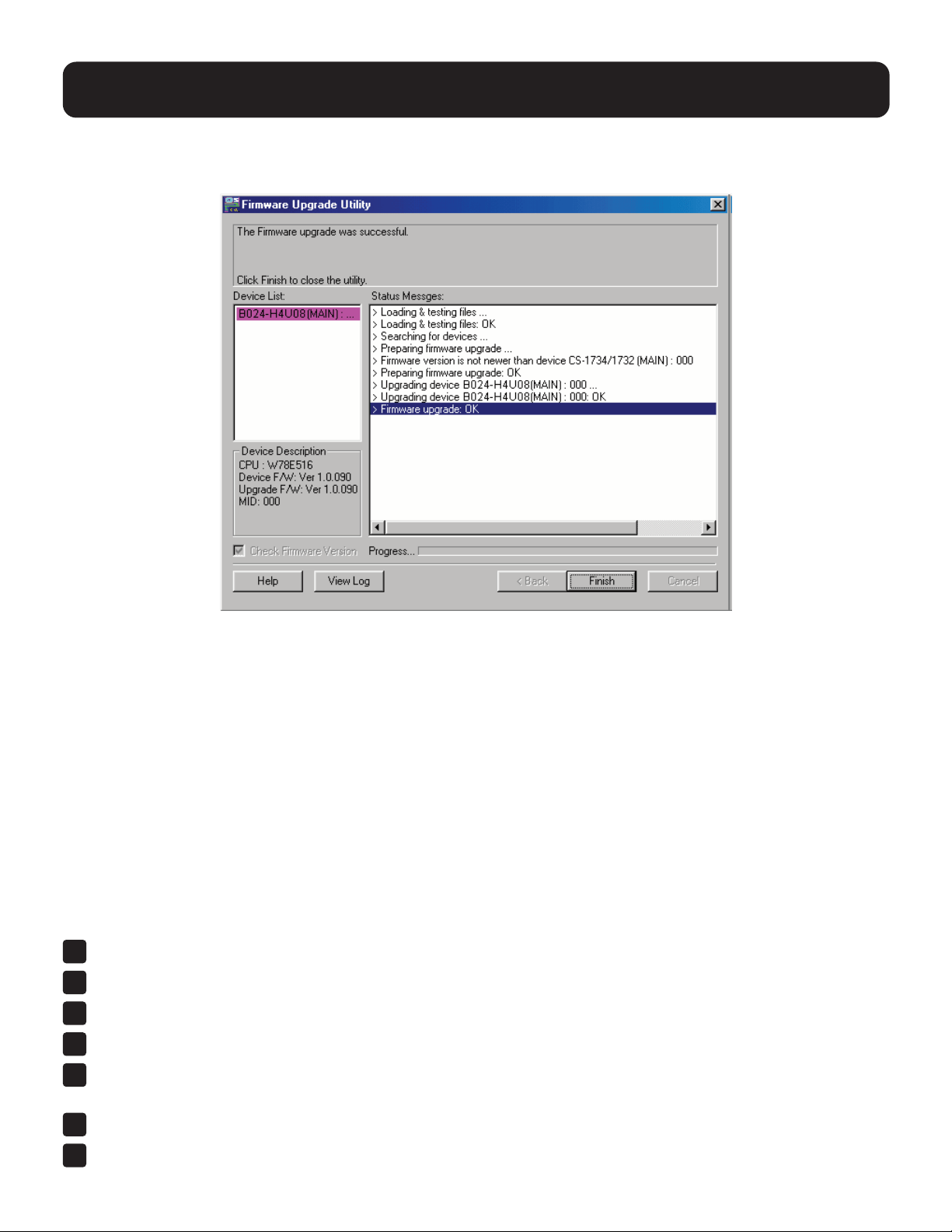
58
13. Firmware Management Utility
13.4 Upgrade Successful
After the upgrade has completed, a screen will appear to inform you that the procedure was successful.
Click Finish to close the Firmware Upgrade Utility.
After a successful completion, the switches will exit Firmware Upgrade Mode and reset.
13.5 Upgrade Failed
If the Upgrade Succeeded screen does not appear, the upgrade failed to complete successfully. Refer to 13.6 Firmware
Upgrade Recovery for how to proceed.
13.6 Firmware Upgrade Recovery
Therearethreeconditionsthatcallforrmwareupgraderecovery:
•Whenarmwareupgradeismanuallyaborted.
•Whenthemainboardrmwareupgradefails.
•WhentheI/Ormwareupgradefails.
Toperformarmwareupgraderecovery,dothefollowing:
1
Powerotheswitch.
2
Connect the Firmware Upgrade Cable to its Firmware Upgrade Port.
3
Slide the Firmware Upgrade Recovery Switch to the Recover position.
4
Power the switch back on and repeat the upgrade procedure.
5
Aftertheswitchhasbeensuccessfullyupgraded,poweritoandslidetheFirmwareUpgradeRecoverySwitch
back to the Normal position.
6
If the switch is one of the cascaded switches, plug it back into the installation.
7
Power the switch back on.
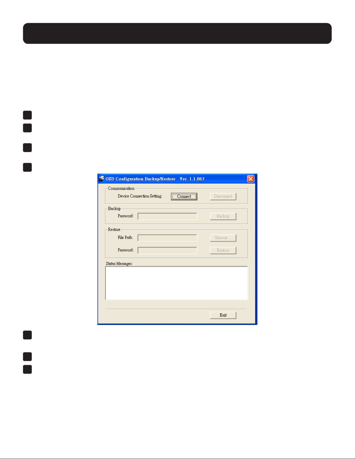
59
13. Firmware Management Utility
13.7 OSD Conguration Backup/Restore
TheFirmwareManagementUtilityletsyoubackupthecurrentOSDcongurationoftheKVMandrestoreitwhennecessary.
StoringtheOSDcongurationsettingsisusefulwhendeployingmorethanoneinstallationthatusesthesamesettings.
13.7.1 Backup
Tostoreabackupletoalocalcomputer:
1
Make sure your computer is connected to the KVM (see 13.2 Preparation and follow steps 1–3).
2
WhenyouhaveselectedtheF4Adminfunction,scrolldowntoOSDCongBackup/Restore.Press[Enter],
then select Enable toinvokeOSDCongBackup/Restoremode.
3
RuntheFirmwareManagementUtility.Inthedialogbox,choose“OSDCongurationBackup/Restore,”
then click Next.
4
In the window that appears, click Connect Device.
5
InthePasswordeld,keyinapasswordforthele.
Note: Setting a password is optional. If you do not set one, the le can be restored without specifying a password.
6
Click Backup.
7
Whenthebrowseraskswhatyouwanttodowiththele,select“Savetodisk,”thensaveitinaconvenientlocation.

60
14. Appendix
14.1 B024-H4U08 and B024-H4U16 Connection Tables
The following tables indicate the relationship between the number of Primary View (PV) units and the number of
computers that they control:
14.1.1 B024-H4U08 (First Level) +
B024-H4U08 (Second Level)
PVs Computers
1 1 – 8
2 8 – 15
3 15 – 22
4 22 – 29
5 29 – 36
6 36 – 43
7 43 – 50
8 50 – 57
9 57 – 64
13. Firmware Management Utility
13.7.2 Restore
Followthesestepstorestoreabackuplefromalocalcomputer:
1
Perform steps 1 to 3 in 13.7.1 Backup.
2
Click RestoretorecoveranOSDcongurationstoredinthelocalcomputer.Ifyouhavepreviouslysetapassword
forthisfeature,enterthepasswordintheprovidedeldbeforeclickingRestore.Aconrmationwindowwillappear.
Click Yes to proceed.
3
BrowsefortheOSDcongurationleyouwanttouseandclickRestore.Makesurethebackupleisinthelocal
computer.
4
Aconrmationwindowappearswhentherestoreprocessisdoneandsuccessful.ClickOK to close it.
14.1.2 B024-DPU16 (First Level) +
B024-DPU16 (Second Level)
PVs Computers
1 1 – 16
2 16 – 31
3 23 – 30
4 31 – 46
5 61 – 76
6 76 – 91
7 91 – 106
8 106 – 121
9 121 – 136
10 136 – 151
11 151 – 166
12 166 – 181
13 181 – 196
14 196 – 211
15 211 – 226
16 226 – 241
17 241 – 256

61
14.1.3 B024-H4U08 (First Level) + B024-H4U08 (Second Level)
PVs Computers
1 1 – 8
2 8 – 15
3 15 – 22
4 22 – 29
5 29 – 36
6 36 – 43
7 43 – 50
8 50 – 57
9 57 – 64
10 64 – 71
11 71 – 78
12 78 – 85
13 85 – 92
14 92 – 99
15 99 – 106
16 106 – 113
17 113 – 120
18 120 – 127
19 127 – 134
20 134 – 141
21 141 – 148
22 148 – 155
23 155 – 162
24 162 – 169
25 169 – 176
26 176 – 183
27 183 – 190
28 190 – 197
29 197 – 204
30 204 – 211
31 211 – 218
32 218 – 225
33 225 – 232
34 232 – 239
35 239 – 246
36 246 – 253
37 253 – 260
14. Appendix
PVs Computers
38 260 – 267
39 267 – 274
40 274 – 281
41 281 – 288
42 288 – 295
43 295 – 302
44 302 – 309
45 309 – 316
46 316 – 323
47 323 – 330
48 330 – 337
49 337 – 344
50 344 – 351
51 351 – 358
52 358 – 365
53 365 – 372
54 372 – 379
55 379 – 386
56 386 – 393
57 393 – 400
58 400 – 407
59 407 – 414
60 414 – 421
61 421 – 428
62 428 – 435
63 435 – 442
64 442 – 449
65 449 – 456
66 456 – 463
67 463 – 470
68 470 – 477
69 477 – 484
70 484 – 491
71 491 – 498
72 498 – 505
73 505 – 512

62
14.2 Specications
B024-H4U08 B024-H4U16
Computer
Connections
Direct 8 16
Max 512 (via Cascade) 256 (via Cascade)
Port Selection OSD, Hotkey, Pushbutton, RS-232 Commands
Connectors
Console
Ports
KB 1 x USB Type-A, Female
Video 1 x HDMI, Female
Mouse 1 x USB Type-A, Female
Speakers 2 x 3.5 mm Audio Jack, Female (Green; 1 x front, 1 x rear)
KVM Ports
KB / Mouse
8 x USB 3.1 Gen1 Type-B,
Female (Blue)
16 x USB 3.1 Gen1 Type-B,
Female (Blue)
Video 8 x HDMI Female 16 x HDMI Female
Speakers
8 x 3.5 mm Audio Jack,
Female (Green)
16 x 3.5 mm Audio Jack, Female
(Green)
F/W Upgrade 1 x RJ11, Female (Black)
Power 1 x DC Jack
USB 3.1 Hub 2 x USB 3.1 Gen1 Type-A, Female (Blue; 2 x front)
Switches
Port Selection 8 x Pushbutton 16 x Pushbutton
Reset 1 x Semi-Recessed Pushbutton
F/W Upgrade 1 x Slide Switch
LEDs
USB Link 8 (Green) 16 (Green)
On-Line / Selected 8 (Orange) 16 (Orange)
Power 1 (Green)
Emulation Keyboard / Mouse USB
Video HDMI: 4096 x 2160 @ 60 Hz
Scan Interval 1–255 Seconds (Default: 5 secs)
Power Consumption DC12V: 9.77W: 88 BTU DC12V: 13.12W: 104 BTU
Environment
Operating Temp 32–104ºF (0–40ºC)
Storage Temp -4–140ºF (-20–60ºC)
Humidity 0–80% RH, Non-condensing
Physical Properties
Housing Metal
Weight 6.85 lb. (3.11 kg) 7.8 lb (3.54 kg)
Dimensions [L x W x H] 17.02 x 8.44 x 1.73 in. (43.24 x 21.43 x 4.40 cm)
14. Appendix
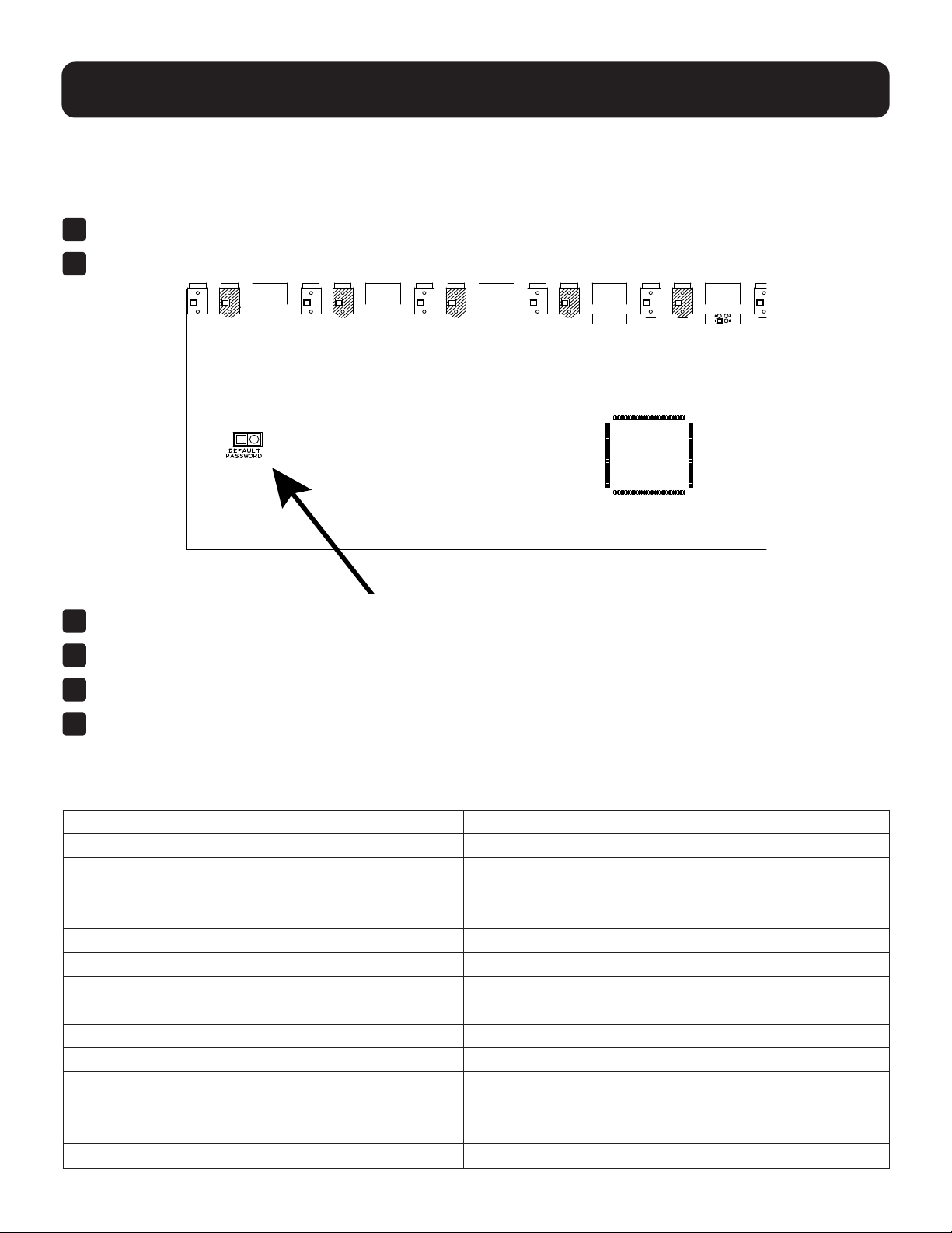
63
14. Appendix
14.3 Administrator Login Failure
If you are unable to perform an Administrator login (e.g. because the username/password information has become
corrupted or you have forgotten it), you can clear the login information with the following procedure:
1
PowerotheKVMandremoveitshousing.
2
Short the jumper labeled DEFAULT PASSWORD.
3
Power on the switch.
4
WhenthefrontpanelLEDsash,powerotheswitch.
5
Remove the jumper cap.
6
Close the housing and restart the KVM. After restarting, you can use the default login procedure to login
(see 9.1 OSD Login).
14.4 Factory Default Hotkeys and Settings
Setting Default
OSD Hotkey [Scroll Lock] [Scroll Lock]
Invoking HSM Hotkey [Number Lock] [-]
Port ID Display Position Upper Left Corner
Port ID Display Duration 3 Seconds
Port ID Display Mode The Port Number plus the Port Name
Auto Scan Interval 5 Seconds
Scan/Skip Mode All Ports
Mouse Emulation Enabled
Screen Blanker Disabled
Logout Timeout Disabled
EDID Mode HDMI Monitor’s EDID
Beeper Enabled
Accessible Ports Full for All Users on All Ports
Video DynaSync Enabled

64
1111 W. 35th Street, Chicago, IL 60609 USA • tripplite.com/support
23-01-236 93406D_RevC
15. Warranty and Product Registration
3-Year Limited Warranty
TRIPP LITE warrants its products to be free from defects in materials and workmanship for a period of three (3) years from the date
of initial purchase.
TRIPP LITE’s obligation under this warranty is limited to repairing or replacing (at its sole option) any such defective products.
To obtain service under this warranty, you must obtain a Returned Material Authorization (RMA) number from TRIPP LITE or an
authorized TRIPP LITE service center. Products must be returned to TRIPP LITE or an authorized TRIPP LITE service center with
transportation charges prepaid and must be accompanied by a brief description of the problem encountered and proof of date and
place of purchase. This warranty does not apply to equipment which has been damaged by accident, negligence or misapplication
orhasbeenalteredormodiedinanyway.
EXCEPT AS PROVIDED HEREIN, TRIPP LITE MAKES NO WARRANTIES, EXPRESS OR IMPLIED, INCLUDING WARRANTIES
OF MERCHANTABILITY AND FITNESS FOR A PARTICULAR PURPOSE. Some states do not permit limitation or exclusion of
implied warranties; therefore, the aforesaid limitation(s) or exclusion(s) may not apply to the purchaser.
EXCEPT AS PROVIDED ABOVE, IN NO EVENT WILL TRIPP LITE BE LIABLE FOR DIRECT, INDIRECT, SPECIAL, INCIDENTAL
OR CONSEQUENTIAL DAMAGES ARISING OUT OF THE USE OF THIS PRODUCT, EVEN IF ADVISED OF THE POSSIBILITY
OFSUCHDAMAGE.Specically,TRIPPLITEisnotliableforanycosts,suchaslostprotsorrevenue,lossofequipment,lossof
use of equipment, loss of software, loss of data, costs of substitutes, claims by third parties, or otherwise.
PRODUCT REGISTRATION
Visit tripplite.com/warranty today to register your new Tripp Lite product. You’ll be automatically entered into a drawing for a chance
to win a FREE Tripp Lite product!*
* No purchase necessary. Void where prohibited. Some restrictions apply. See website for details.
RegulatoryComplianceIdenticationNumbers
Forthepurposeofregulatorycompliancecerticationsandidentication,yourTrippLiteproducthasbeenassignedauniqueseries
number. The series number can be found on the product nameplate label, along with all required approval markings and information.
When requesting compliance information for this product, always refer to the series number. The series number should not be
confused with the marketing name or model number of the product.
WEEE Compliance Information for Tripp Lite Customers and Recyclers (European Union)
Under the Waste Electrical and Electronic Equipment (WEEE) Directive and implementing regulations, when customers buy
new electrical and electronic equipment from Tripp Lite they are entitled to:
• Send old equipment for recycling on a one-for-one, like-for-like basis (this varies depending on the country)
• Send the new equipment back for recycling when this ultimately becomes waste
TrippLitehasapolicyofcontinuousimprovement.Specicationsaresubjecttochangewithoutnotice.Photosandillustrationsmay
dierslightlyfromactualproducts.