Page 1
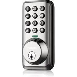
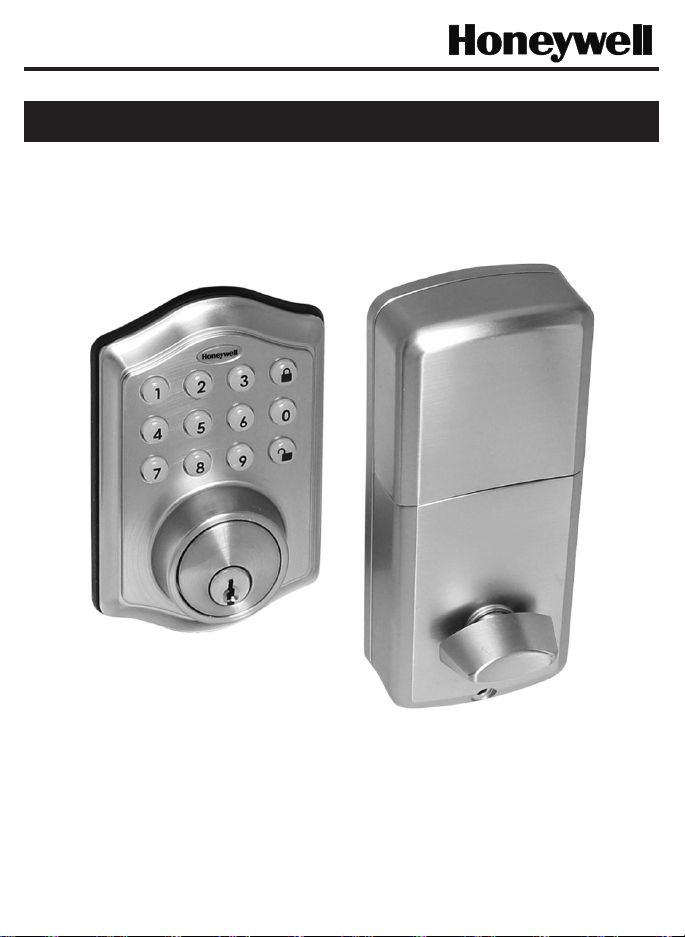
Model DDBKP
Read this manual carefully before installing and operating!
ENGLISH
Installation & Operation Guide
Digital Deadbolt

Page 2
Index
INSTALLATION INSTRUCTIONS
Package Contents / Tools Required..........................................................
Prepare Door and Jamb.............................................................................
Adjusting Deadbolt Latch Set..................................................................
Installing Deadbolt Latch Set.....................................................................
Installing Exterior Assembly........................................................................
Installing Interior Assembly........................................................................
OPERATION INSTRUCTIONS
Digital Keypad Overview.............................................................................
Locking and Unlocking / Changing Programming Code /
Adding User Codes......................................................................................
Deleting User Codes / Automatic Lock Function /
Sound On and Off........................................................................................
Secure Lock-out Period / Restore Factory Settings /
Low Battery Warning / Consumer Friendly Message Guide....................
Installation Trouble Shooting...............................................................
Customer Service........................................................................................
Template.......................................................................................................
Programming Record..................................................................................
Limited Warranty.................................................................................
Page 1
Page 2
Page 3
Page 4
Page 5
Page 6-8
Page 9
Page 10
Page 11
Page 12
Page 13
Page 14
Page 15-16
Page 17
Back
Cover
Page 1
INSTALLATION INSTRUCTIONS
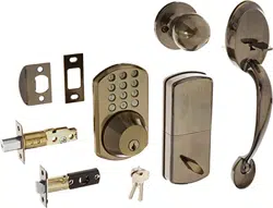
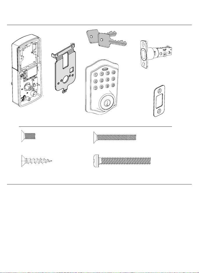
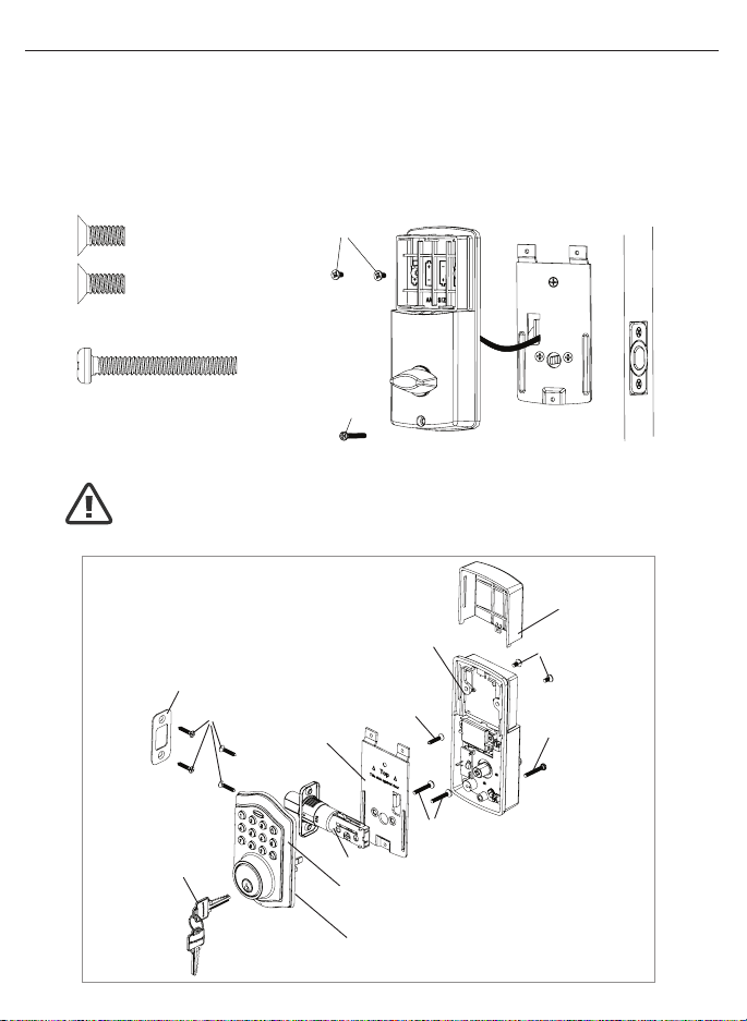
Package Contents
Tools Required
Tools Required for Installation
on Pre-drilled Doors:
•PhillipsScrewdriver
Tools Required for Installation
on Doors That Require Drilling:
•Drill
•TapeMeasure
•Pencil
•2-1/8”(54mm)DrillHoleSaw
•1”(25mm)Drill
•1/16”(2mm)Drill
•Chisel
•Hammer
•PhillipsScrewdriver
DO NOT RETURN TO STORE! If any parts are missing or damaged,
pleasecallCustomerServicetollfreeat1-877-354-5457(M-F7am–5pmPST)
Deadbolt Strike Plate
DeadboltLatchSet(Adjustable)
2-3/8”(60mm)to2-3/4”(70mm)
5/16”(8mm)Screws-2ea. 1”(25mm)Screws-2ea.
3/4”(19mm)Screws-5ea. 1-3/8”(35mm)Screws-1ea.
InteriorAssembly
Mounting Plate
ExteriorAssembly
Entrykeys(2ea.)
Page 2
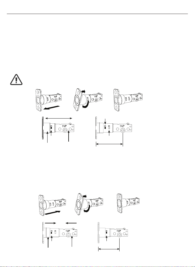
ADJUSTABLEDEADBOLTLATCHSET
NOTE: Deadbolt Latch Set is shipped with the backset set at 2-3/8” (60mm)
Measurethebackset(backsetisdistancebetweenedgeofthedoorandthe
centerofLock).
1. TO CONVERT FROM 2-3/8” (60mm) BACKSET TO 2-3/4” (70mm) BACKSET
a.Holdlatchwithnumbersfacingforwardandthumbpressingonthebolt(Figure1a).
b.Rotatethecylindercoverclockwise(Figure1b).
c.Pullandtwisttheextensionplateallthewayout(Figure1c).
d.Rotatethecylindercovercounterclockwisesothatthemarkingalignswith
the2-3/4”(70mm)positionindicator(Figure1d).
2. TO CONVERT FROM 2-3/4” (70mm) BACKSET TO 2-3/8” (60mm) BACKSET
a.Holdlatchwithnumbersfacingforwardandthumbpressingonthebolt(Figure2a).
b.Rotatethecylindercoverclockwise(Figure2b).
c.Pushandtwisttheextensionplateallthewayin(Figure2c).
d.Rotatethecylindercovercounterclockwisesothatthemarkingalignswith
the2-3/8”(60mm)positionindicator(Figure2d).
Figure1a
Figure2a
Figure1b
Figure2b
Figure1c
Figure2c
Figure1d
Figure2d
Extension plate
Extension plate
Cylindricalcover
Cylindricalcover
Yourlatchisnowset
2-3/8”(60mm)backset
Yourlatchisnowset
2-3/4”(70mm)backset
2-3/8”
(60mm)
2-3/8”
(60mm)
2-3/4”
(70mm)
2-3/4”
(70mm)
2-3/8”
(60mm)
NOTE: Do not extend Cylindrical Cover past 2-3/4” (70mm)
Page3
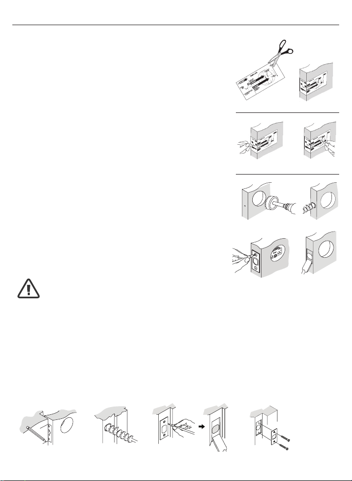
NOTE: For installation on doors with pre-drilled holes skip to page 4.
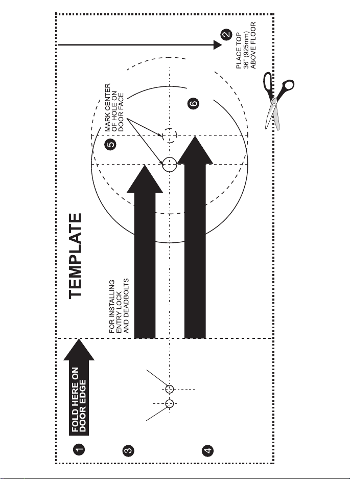
1. TEMPLATE
a.Cutouttemplateprintedonpage15ofthisManual
(Figure1a).
b. Foldtemplateandplaceondoor36”(925mm)from
thegroundasmarked(Figure1b).
2. MARK THE DOOR FOR DRILLING
b. Mark center hole on door edge through guide on
templatefor1”(25mm)latchbolt(Figure2a).
a. Mark center hole on door face through guide on
templatefor2-3/8”(60mm)or2-3/4”(70mm)
backset(Figure2b).
3. DRILL AND CHISEL DOOR
a.Drill2-1/8”(54mm)holethroughdoorfaceasmarked
forlockset(Figure3a).
b.Drill1”(25mm)holeincenterofdooredgefor
DeadboltLatchAssembly(Figure3b).
c.InsertDeadboltLatchAssemblyinholekeepingit
paralleltofaceofdoor.Markoutlineandremovelatch
(Figure3c).
d.Chisel1/8”(3mm)deeporuntillatchfaceisush
withdooredge(Figure3d).
4. MARK AND DRILL DOOR JAMB
a. MarkcenterholeonedgeofjambevenwiththecenteroftheLatchBoltondoor
edge.(Figure4a).
b.Drill1”(25mm)hole1-3/16”(30mm)deepindoorjamboncentermark
(Figure4b).
c.OutlineoutsideedgesofStrikePlate(Figure4c).
d.Chisel1/8”(3mm)deepforStrikePlateoruntilush(Figure4d).
e.InstallStrikePlateusingtwo3/4”(19mm).screwsprovided(Figure4e).
PREPAREDOORANDJAMB
Figure4a Figure4b
Figure4c Figure4e
Figure4d
NOTE: For Drive in Latch, drill hole size indicated on template and press
until it is flush with door edge.
U
P
Figure1a
Figure2a Figure2b
Figure3a
Figure3c
Figure1b
Figure3b
Figure3d
Page4
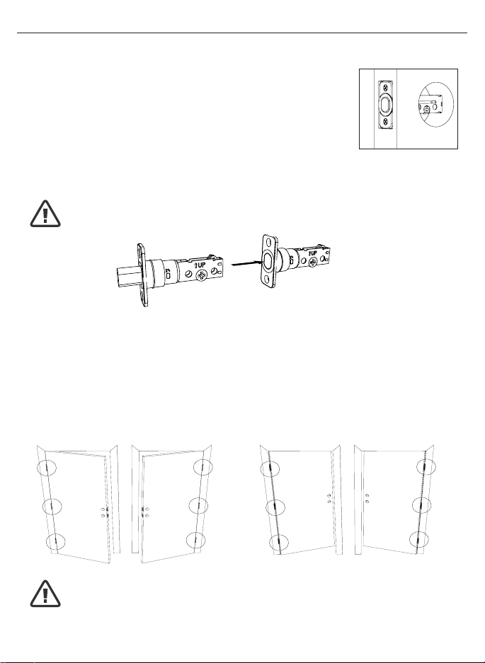
1. INSTALLING THE DEADBOLT LATCH SET (need phillips head screwdriver)
a.InsertDeadboltLatchSetintodooredgeholewiththeword
“UP”andthearrowontheextensionplatefacingUP.Cross
shapedspindleconnectorwillbeatthebottomoftheDeadbolt
LatchSet(Figure1a).
b.Makesurethefaceplatesitsushwiththedoor.Donotforce
thelatchintothemortiseush.Chiseloutexcessmaterialif
necessaryforausht.
c.Usingtwo3/4”(19mm).screwsprovided,screwthelatchintothe
doorwithahandheldscrewdriver.DONOTOVERTIGHTEN.
2. IDENTIFYING YOUR DOOR HANDING
Stand outside the door
a.IfthehingesareontheleftyourdoorisLeftHanded(Figure2a).
b.IfthehingesareontherightyourdoorisRightHanded(Figure2b).
NOTE: Deadbolt Latch must be retracted when installing
NOTE: You are standing outside the door
INSTALLINGDEADBOLTLATCHSET
OUT SWING DOOR IN SWING DOOR
Figure2a
Left Handed Door
Hinges are on the left side
Left Handed Door
Hinges are on the left side
Right Handed Door
Hinges are on the right side
Right Handed Door
Hinges are on the right side
Figure2b
Figure1a
Deadbolt Latch Extended
Deadbolt Latch Retracted
Page5
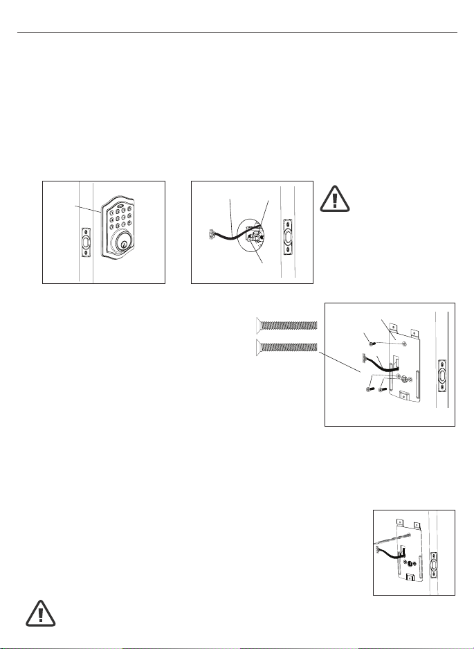
2. SECURING THE EXTERIOR ASSEMBLY TO THE DOOR
a.Fromthesidemarked“Thissideagainst
door”,routetheControlWirethroughthe
rectangular slot in the Mounting Plate
(Figure2a).
b.PlaceMountingPlateagainstdoorwithtailpiecepassing
throughthecenterholeinthethreeholeset(Figure2b).
c.SecuretheMountingPlatetotheExteriorAssemblyusing
two1”(25mm)Screws(Figure2c).
d.HandtightenwithaPhillipsScrewdriverleavinglooselyconnected(Figure2d).
e. Check that the Rubber Gasket is properly aligned and correct as necessary
(Figure2e).
f.Checkverticalalignmentofthelock(Figure2f).
g.TightensecurelywithahandheldPhillipsScrewdriver.DO NOT OVER TIGHTEN
3. OPTIONAL INSTALLATION
a.Usinga1/16”(2mm)drillbit,drillapilotholeinyourdoorusingthe
MountingPlateupperholeasaguide(Figure3a).
b. Insert one 3/4”(19mm)screwandtighten.
1. INSTALLING THE EXTERIOR ASSEMBLY
WorkwiththeDoorOpenforeasyaccess.
a.UnpacktheExteriorAssembly.Usecaretonotscratchthegreencircuitboard
during handling and installation.
b.CheckthattheRubberGasketisproperlyseatedontheExteriorAssembly
(Figure1a).
c.InserttheExteriorAssemblyontothedoorwiththetailpiecegoingthroughthe
Deadbolt Latch Set cross shaped spindle connector in the VERTICAL POSITION.
RoutetheControlWirethroughthedoorovertheDeadboltLatchSet(Figure1b).
NOTE: Deadbolt Latch must be retracted when installing
NOTE: Tailpiece must be
positioned vertically
NOTE: You are standing outside the door
INSTALLINGEXTERIORASSEMBLY
Right handed door view
Rubber
Gasket
Control
Wire
Tailpiece
(Vertical)
Latch
Hole
Mounting Plate
3/4”(19mm)screw
(OptionalInstallation)
1”(25mm)screws
Control Wire
Figure1a Figure1b
Figure3a
Figure2a-2f
NOTE: Lock and unlock using the key to see if
the Deadbolt Latch is opening and closing easily.
Page6
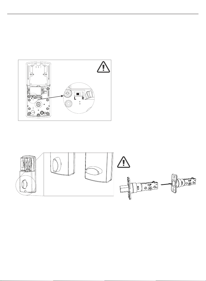
INSTALLINGINTERIORASSEMBLY
1. SET THE ENTRY SWITCH FOR LEFT OR RIGHT HANDED DOOR
a.Gentlymovetheswitchto“L”forLeftHandedDoor(Figure1a).
b.GentlymovetheSwitchto“R”forRightHandedDoor(Figure1b).
2. SET THE INTERIOR KNOB POSITION FOR LEFT OR RIGHT HAND HINGED DOORS
a.TheInteriorKnobgoesintheVerticalpositionforRightHandedDoors(Figure2a).
b.TheInteriorKnobgoesintheHorizontalpositionforLeftHandedDoors(Figure2b).
3. ATTACH THE CONTROL WIRE TO THE INTERIOR ASSEMBLY
a.UsecaretoattachtheControlWiremaleplugtotheInteriorAssemblyfemale
socket connector.
b.DonotforcetheControlWiremaleplugintotheInteriorAssemblyfemale
socket connector.
c.TheControlWiremaleplughastwoalignmenttabsonthesmoothsideofthe
plugwhichisthetopoftheplug.
d.TheControlWiremaleplugisinsertedwiththesmoothsideupintotheInterior
Assemblyfemalesocketconnector.
NOTE: Make sure
deadbolt Latch
is retracted
Left Handed Door
(Horizontal)
Entry Switch
(Left or Right)
Right Handed Door
(Vertical)
UnpacktheInteriorAssembly.Removethebatterycoverbyslidingthecoverupward.Locatethe
screwsholdingtheMountingPlatetotheInteriorAssembly.Removethescrewstoreleasethe
MountingPlatefromtheInteriorAssembly.
Figure1a-1b
Figure2a-2b
Page7
INSTALLINGINTERIORASSEMBLY(CONT.)
4. ATTACH THE INTERIOR ASSEMBLY TO DOOR
a.PositiontheInteriorAssemblyoverthetailpieceandpushtheInteriorAssembly
againstthedoor(Figure4a).
b.Usingtwo5/16”(8mm)screws and one 1-3/8”(35mm)screw, attach
theInteriorAssemblytotheMountingPlate.DO NOT OVER TIGHTEN SCREWS
(Figure4b).
5/16”(8mm)screws
1-3/8”(35mm)screw
NOTE: Lock and unlock using Interior Knob to see if the
latch is opening and closing easily.
INSTALLATION OVERVIEW
Strike Plate
BatteryCover
InteriorAssembly
Key
ExteriorAssembly
Rubber Gasket
Mounting Plate
Latch
5/16”(8mm)
screws
Optional
3/4”(19mm)
screw
3/4”(19mm)
screws
1-3/8”(35mm)
screws
1”(25mm)
Screw
Figure4a-4b

Page8
INSTALLINGINTERIORASSEMBLY(CONT.)
5. Installing Batteries
a.Insert4AAhighqualityAlkalinebatteriesintotheBatteryCompartmentinthe
directionnoted+/-ontheCompartment.TheLockwillbeep2times,thekeypad
willilluminateblue,andtheHoneywellbuttonwillashgreentwicetosignifythat
ithasreceivedpower(Figure5a).
b.SlidetheBatteryCoverdownintothetrackontheInteriorAssemblytocover
thebatteries(Figure5b).
6. Testing Lock
With the Door Open
a.TesttheLockusingtheinteriorKnob.Theboltshouldmovesmoothly.
b.TestthelockusingtheKeypad.Tolockpressandthenpress“1234”
to unlock.
Override
AccessKey
ExteriorAssembly
InteriorAssembly
Interior
Knob
Battery
Cover
Light Indicator
Keypad
NOTE: Do not touch the keypad until the blue light turns off.
Do not use rechargeable batteries or non-alkaline batteries.
Figure5a-5b
Page9
OPERATION INSTRUCTIONS
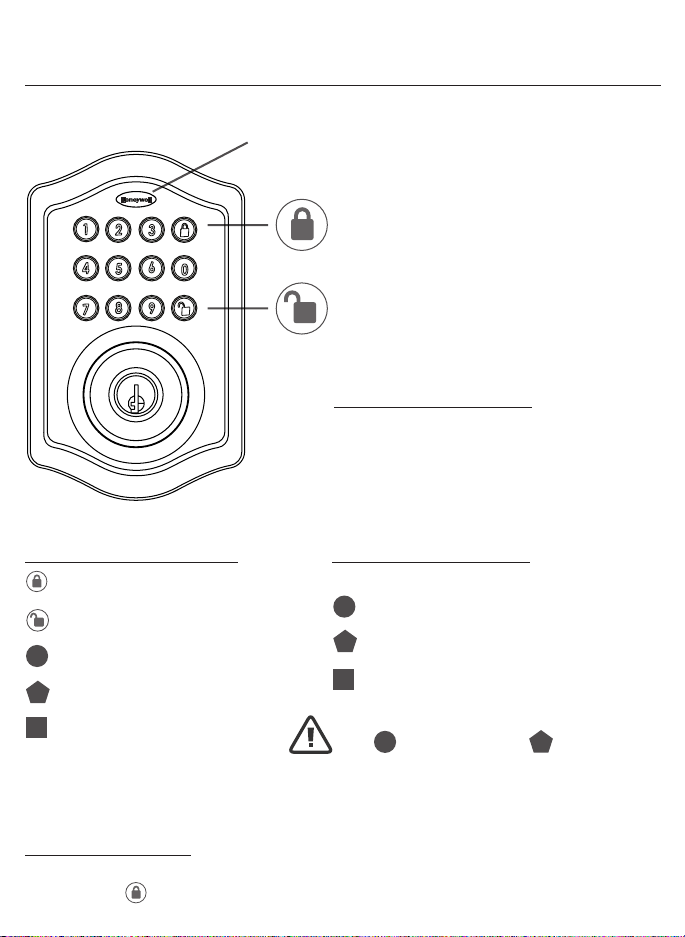
ExteriorAssemblyOverview
Indicator light
Green
•IndicatesSuccessfulProgrammingStep
•IndicatesUnlockingisSuccessful
Red
•IndicatesFailedProgrammingStep
•IndicatesLockingisSuccessful
Electronic lock requires (4) High Quality
AA Alkaline batteries. When all 4 batteries
are installed in the correct position, hear 2
beeps and the keypad will illuminate blue.
DO NOT TOUCH the keypad until the keypad
stops illuminating.
Lock-Usedtolockdoor
Clear -Usedtoclearwrongkeypadentries
Unlock-Usedtounlockdoor
Programming -Usedinprogrammingsteps
5 Seconds -Completealltheprogrammingstepsintheprogrammingmodewithin5seconds.
Clear -Usethekeytoclearentriesincaseawrongbuttonispushed.
Lock button
Unlock button
FactorySettings
The lock comes factory preset with a:
Please change the Programming
Code and the User Code
as soon as possible after installation
to insure security.
Programming code - 123456
User code - 1234
User ID - 01
ID
PC
PC
UC
UC
Batteries(notincluded)
Programming Symbols
Lock/Clear
Unlock/Programming
Programming Code
User Code (4-8 digits)
User ID (01-50, 2 digits)
ID
PC
UC
Programming Tips
Page10
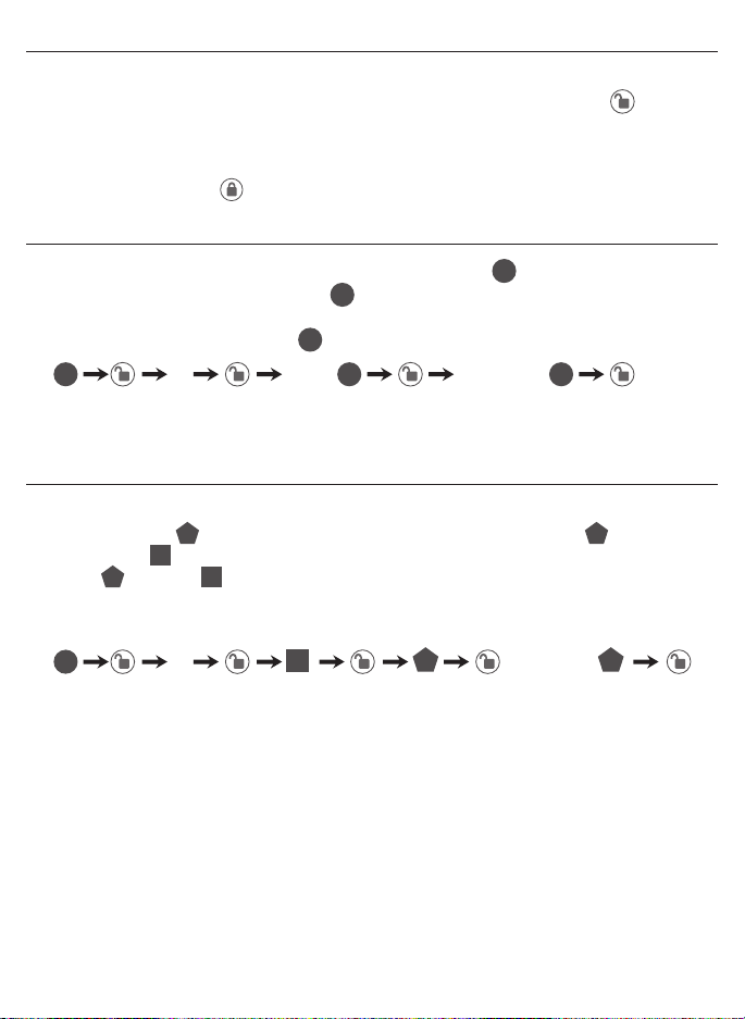
TO UNLOCK THE LOCK
UsingKeypad:EnteravalidUserCode(defaultcodeis1234)andpressandhear
1 beep and lights green.
TO LOCK THE LOCK
Using Keypad: Press and then hear 2 beeps and lights red.
CHANGECURRENTORPRESETPROGRAMINGCODE
FactorydefaultProgrammingCode=123456,thisisthemasterpasswordfor
yourlock.Allprogrammingfunctionsrequirethiscode.Followthebelowsequenceto
changetheProgrammingCodetoyourcustom6digitcombination.
TOADDANEWUSERCODE(youcanaddupto50newusercodes)
TheUserCodemustbea4-8digitcombination.EachUserCodeisthenlinked
toaUserID(whichisanynumberbetween01-50)toidentifyanindividualUser
Code.(UserID1-9shouldbeenteredas01-09sotheyare2digits).
Hear 1 beep and Light Indicator illuminates green
RecordNewandChangedCodesonProgrammingRecordlocatedonPage17
Hear 1 beep and Light Indicator illuminates green
NOTE:WhenaNEWUSERCODEisset,thedefaultfactorycode(1234)isdeleted
for safety.
RecordNewandChangedCodesonProgrammingRecordlocatedonPage17
123456 08 56785678
Forexample:toaddtheUserID-08toUserCode-5678,enterthefollowing:
4newRe-enter
1Re-enter
Locking and Unlocking
Changing Programming Code
AddingUserCodes
ID
ID
ID
UC UC
UC UC
UC
PC
PC
PC PC
PC
PC
PC
Page 11
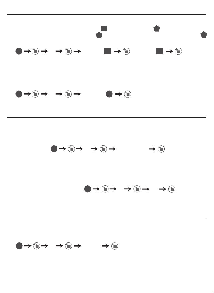
DELETE ONE EXISTING OR PRESET USER CODE
TheunitcomeswithafactoryUserID=01forUserCode=1234.
IMPORTANT:Todelete1UserCode,thelockmusthavemorethan1UserCode
in its database.
SET OR CANCEL AUTO LOCK
You can set the lock to automatically close after each time the lock is opened. Time
valuerange=20-900seconds,enterthefollowing:
Youcan“mute”orturnthe“soundon”onyourlockbyenteringthefollowing.
(Factorysettingissoundon).
DELETE ALL USER CODES
IMPORTANT:thiswilldeletetheusercodesbutnottheprogrammingcode,enter
thefollowing
Hear 1 beep and Light Indicator illuminates green
SetAutoLock:
Hear 1 beep and Light Indicator illuminates green
SoundOff(1)-LightIndicatorilluminatesgreen
SoundOn(2)-Hear1beepandLightIndicatorilluminatesgreen
To cancel Auto Lock set the time to 00, enter the following:
CancelTimeValueAutoLock:
Hear 1 beep and Light Indicator illuminates green
Hear 1 beep and Light Indicator illuminates green
2Existing re-enter
5TimeValue
61or2
500
3re-enter
Deleting User Codes
AutomaticLockFunction
Sound On and Off
PC
PC
PC
PC
PC PC
ID
UC
UC
UC
ID ID
1=SoundOff
2=SoundOn

Page 12
WarningsoundsandLEDashesredafter4incorrectcodeattempts:Keypadshuts
downfor30seconds.
To reset the lock to the original factory settings including the Programming Code
andallUserCodesremoveonebatteryfor10seconds.Reinsertthebatteryand
waitforalongandshortbeep.Press3timeswithin3seconds.Thelockwillbeep
andthelightindicatorwillturngreen.
BeepsandLEDashesredfor5seconds.Pleasereplacewithgoodquality
alkaline batteries.
Note:RomovingbatteriesdoesnoteraseactiveProgrammingorUserCodes.
NOTE:Whenbatteryisunderlowvoltage,thelockwillgivethe(LowBatteryWarning:BeepsandLEDashesredfor5seconds).During
thistimeyourlockcanstillwork.Howeveroncethevoltageislowerthan4.3V(calledSuper-LowVoltage),theoperationofthelockingand
unlockingwillnotwork,usermustreplacebatteriesimmediately.
Secure Lock out Period
RestoreFactorySettings
LowBatteryWarning
ConsumerFriendlyMessageGuide
UC
PC
Unlock/Validprogramming: 1 long beep and LED illuminates green
Lock: 2 short beeps and LED illuminates red
InvalidProgramming: 2shortbeepsandLEDashesredtwice
LowVoltage: Beepsfor5seconds
(7/9timesdependsonoperationisunlock/lock)
SuperLowVoltage: 4shortbeepsandLEDashesredfourtimes
4Incorrectcodeentryattempts: 2 short beeps and LED illuminates red each attempt
Poweron: 1 long beep and 1 short beep and LED illuminates green
Chip Reset: 1 long beep and 1 short beep and LED illuminates green
(mayoccurseveraltimesoronceinawhile)
Lock Error: 3longbeepsLEDashesredthreetimes
Repeat operation after Lock Error: 2 short beeps three times LED ashes red six times

Page13
INSTALLATIONTROUBLESHOOTING
Issue Solution
LatchWorkingBackwards-
Lockunlockswhenlock
button is pushed or locks
whenunlockbuttonorcodeis
pushed.
Directionswitchissettoincorrectsetting.
RemovetheInteriorAssemblyandmovethe
switchtotheoppositedirection.
•Checkthatyourswitchissetinthecorrect
position Left or Right Handed door.
If Correct
•RotateTurnknobandreinstallInterior
Assembly.RetestagainwhileholdingInterior
Assemblyinplace.
InteriorAssemblyknobwill
not turn.
Knoborverticaltailpieceisinstalledin
incorrectposition.RemoveInteriorAssem-
bly and reposition the Interior Knob. With the
DeadboltLatchretractedverifythatthetailpiece
isvertical.
Lockwillnotfunction
electronically.
•Checkthatallbatteriesarefreshhighquality
AlkalineBatteries.
•Checkforproperpolarity(+-)ofallbatteries.
•CheckthattheControlWireisattachedtothe
InteriorAssembly.
Lockgiveserrorsignalwhen
opening or locking and Dead-
boltLatchwillnotextendor
retractcompletelywhendoor
is closed.
Unlock door using key or interior knob. While
door is open, check that the Deadbolt Latch
operates smoothly. Check for proper alignment
ofthestrikeplate,adjustasneededtoassure
there is no binding against the Deadbolt Latch.
Deadbolt Latch is sticking. Installationscrewsofthelockmaybetootight
andhavetobeloosened.
•RemoveInteriorAssembly.
•SlightlyloosentheMountingPlatescrews.
•LockandunlockusingtheKey.
•ReattachControlWireandInteriorAssembly.

Page14
EMAIL:[email protected]
WEBSITE:www.honeywellsafes.com
ADDRESS:ConsumerAssistanceDept.
LHLicensedProducts,Inc.860EastSandhillAvenueCarson,CA90746USA
TELEPHONE:US/Canada1-877-354-5457(TollFree)
Mexico01-800-288-2872AfterEnglishvoicerecordingstopsyoumustthenenter800-
860-1677
tocompleteyourcall.(TollFree)
Australia0011-800-5325-7000(TollFree)
Germany/NewZealand00-800-5325-7000(TollFree)
OtherCountriesXX*-310-323-5722(TollChargesApply)
XX*-DialU.S.CountryCoderst
CALLCENTERHOURS:US/Canada7am–5pm(PST**)Mon–Fri(Subjecttochange)
CALLBACKHOURS:OtherCountries7am–8pm(PST**)Mon–Fri(Subjecttochange)
PST**-LocaltimeinLosAngeles,CA,USA
INTERNATIONALCALLBACKHOURS:
IfyouneedtospeakwithaconsumerassistantandcannotcontactusduringtheCall
Centerhoursabove,pleasesendanemailorleaveatelephonemessage,includingyour
Name, Telephone Number and the best time for us to contact you during the Call Back
hoursaboveandwewillmakeoureveryefforttocontactyouandhelpansweranyof
your questions or concerns.
*InsertcorrectCountryCode
**LocalTimebasedonLosAngelesCaliforniaUSA
CONSUMERASSISTANCE
Page15
2-3/8” (60mm) BACKSET
2-3/4” (70mm) BACKSET
THENDRILL1”(25mm)HOLE
INCENTERDOOROFEDGE
2”(50mm)INDEPTH
MARK
FOR1-3/4”
(45mm)
DOOR
DRILL
2-1/8”(54mm)
HOLE
MARK
FOR1-3/8”
(35mm)
DOOR
IMPORTANT!
PLACETEMPLATE
ONHIGHEDGEOF
DOORBEVEL

Page16
BACK OF
TEMPLATE

Page17
My Codes: Date Created
ProgrammingCode (6digits)//
UserCode01 (4-8digits)//
UserCode02 (4-8digits)//
UserCode03 (4-8digits)//
UserCode04 (4-8digits)//
UserCode05 (4-8digits)//
UserCode06 (4-8digits)//
UserCode07 (4-8digits)//
UserCode08 (4-8digits)//
UserCode09 (4-8digits)//
UserCode10 (4-8digits)//
UserCode11 (4-8digits)//
UserCode12 (4-8digits)//
UserCode13 (4-8digits)//
UserCode14 (4-8digits)//
UserCode15 (4-8digits)//
UserCode16 (4-8digits)//
UserCode17 (4-8digits)//
UserCode18 (4-8digits)//
UserCode19 (4-8digits)//
UserCode20 (4-8digits)//
UserCode21 (4-8digits)//
UserCode22 (4-8digits)//
UserCode23 (4-8digits)//
UserCode24 (4-8digits)//
UserCode25 (4-8digits)//
Programming Record

Page18
TheHoneywellTrademarkisusedunderlicensefromHoneywellInternationalInc.Honeywell
InternationalInc.makesnorepresentationsorwarrantieswithrespecttothisproduct.
MDDBKPE-20160115www.honeywellsafes.com
Manufactured by:
LH Licensed Products, Inc.
860EastSandhillAvenue
Carson,CA90746
Lifetime Mechanical and Finish Warranty / 1 Year Limited Electronics Warranty
Thisproductcomeswithalifetimemechanicalandnishwarrantyandaoneyearlimited
electronicswarrantytotheoriginalresidentialconsumeragainstdefectsinmaterialand
workmanshipundernormaluseaslongastheoriginalresidentialpurchaseroccupiesthe
residentialpremisesuponwhichtheproductwasoriginallyinstalled.
ORIGINALRESIDENTIALCONSUMER
Thiswarrantyisnottransferable,andappliestotheoriginalpurchaseronly,aslongastheoriginal
purchaseroccupiestheresidentialpremisesuponwhichtheproduct(s)wasoriginallyinstalled.
Proofofpurchase(originalsalesreceipt)andownershipmustaccompanyallwarrantyclaims.
Allnon-homeownerpurchasers(includingpurchasersforindustrial,commercialandbusinessuse)
arenotcoveredunderthetermsofthiswarranty.
WHATISNOTCOVERED
Thiswarrantyisnullandvoidiftheproductwasusedforpurposesforwhichitwasnotdesigned.
ThiswarrantyDOESNOTCOVERnormalwearandtearofpartsordamageresultingfromanyof
thefollowing:negligentuse,misuseorabuseoftheproduct,orusecontrarytoorinviolationof
writteninstructionsprovidedbyLHLicensedProducts,Inc.Further,thiswarrantydoesnotcover
ActsofGod,suchasre,ood,hurricanesandtornadoes.ThiswarrantyDOESNOTCOVER
scratches,abrasions,deteriorationduetotheuseofpaints,solventsoruseofcleaners
containingabrasives,alcoholorothersolvents,whetherperformedbyacontractor,service
company,oryourself.ThiswarrantyDOESNOTCOVERproduct(s)usedincommercial
applications, used in common area applications, disassembly, repair or alteration by anyone other
than LH Licensed Products, Inc., improper installation or exposure to extremes of heat or humidity.
ThiswarrantyDOESNOTCOVERanylosses,injuriestopersonsorlossofproperty,general
damagesorcosts,andshippingandfreightexpensesrequiredtoreturnproduct(s)to
LH Licensed Products, Inc. LH Licensed Products, Inc. shall not be liable for any indirect,
incidental or consequential damages of any nature relating to this lock. LH Licensed Products, Inc.
isalsonotresponsibleforcostsassociatedwithremovingorreinstallingtheproduct.
ADDITIONALTERMS
LH Licensed Products, Inc. does not authorize any person to create for it any obligation or
liabilityinconnectionwiththeProduct.LHLicensedProducts,Inc.’smaximumliabilityhere
under is limited to the original purchase price of the Product. No action arising out of any claimed
breachofthiswarrantybyLHLicensedProducts,Inc.maybebroughtbytheoriginalresidential
purchasermorethanone(1)yearafterthecauseofactionhasarisen.