SEARS
Installation
Instructions
CULAR
ED
«
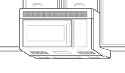
1.3
Cu.
ft
/
JOOW(IEC
705
Rating
Standard)
MICROWAVE
OVEN
Model
No.
721.67600
721.67601
721.67602
721.67680
721.67681
721.67682
Sd)
|
_
|
\
re
et
SSS
———————————
Ee
sn
a
————
a
a’
[ssn
mene
tenner
orn ono
tnoercheoen
enemas
ree
amore
any
ee
al
%
z
O
na
)
|
)
|
CAUTION:
Read
and
save
these
installation
instructions.
Sears,
Roebuck
and
Co.,
Hoffman
Estates,
IL.
60179
U.S.A.
YOUR
SAFETY
FIRST
BEFORE
YOU
START
e
Proper
installation
is
the
installer's
responsibility!
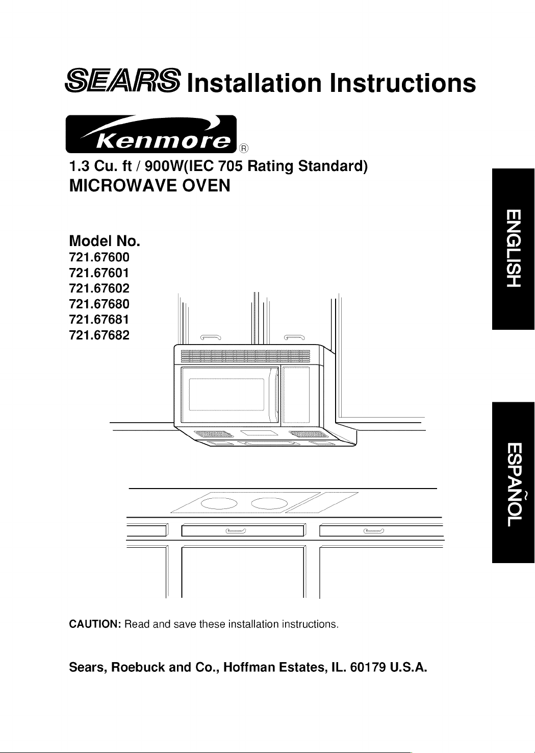
—
Read
the
entire
manual
before
you
begin.
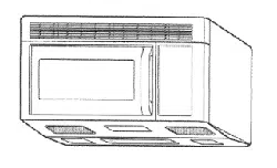
The
Model
number
label
is
located
on
the
oven
front.
See
Figure
1.
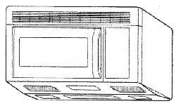
Mounting
plate
is
located
on
back
side
of
microwave
oven.
See
Figure
2.
BE
SURE
TO
READ
THE
FOLLOWING
SAFETY
INSTRUCTIONS:
By
i
l
Mounting
plate
VJ
Gas
Back
of
oven
Model
Number
Label
Figure
1
Figure
2
A
WARNING
&
FOR
YOUR
SAFETY:
@
You
will
need
TWO
people
to
install
this
oven.
It
is
heavy
and
could
cause
personal
injury
if
not
handled
properly.
The
dimensions
of
the
oven
are
as
follows:
MODEL
NO
:
721.67600, 721.67601, 721.67602, 721.67680, 721.67681,
721.67682
Height
:
16
7/16
inches
Width:
29
15/16
inches
Depth
:
15
3/8
inches
Weight
:
58
pounds
e
Avoid
Electrical
Shock!
~—
Before
you
drill
into
the
wall,
note
where
electrical
outlets
are
and
where
electrical
wires
might
be
behind
concealed
the
wall,
YOU
COULD
GET
AN
ELECTRIC
SHOCK
it
you
contact
electrical
wires
with
your
drill
bit.
—
Locate
and
disconnect
the
power
of
any
electrical
circuits
that
could
be
affected
by
installing
this
oven.
IF
YOU
DO
NOT
DISCONNECT
THE
POWER,
YOU
COULD
GET
AN
ELECTRIC
SHOCK.
e
ELECTRICAL
RATING
OF
THIS
OVEN
:
120V
AC.
60
Hz.
11.9
Amps
/
1350
Watts
(Microwave
oven
only)
12.9
Amps
/
1500
Watts
(Microwave
oven
+
Cooktop
Lamps
+
Ventilation
Fan)
—
You
need
a
120volt,
60Hz,
AC
only,
15
or
20ampere,
fused
electrical
supply
(located
in
the
cabinet
above
the
microwave
as
close
as
possible
to
the
microwave
circuit)
serving
only
the
microwave.
YOUR
SAFETY
FIRST
e
THIS
APPLIANCE
MUST
BE
GROUNDED!
—
If
there
is
an
electrical
short
circuit,
grounding
reduces
the
risk
of
electrical
shock
by
providing
an
escape
wire
for
the
electric
current.
This
appliance
is
equipped
with
a
cord
having
a
grounding
wire
with
a
grounding
plug.
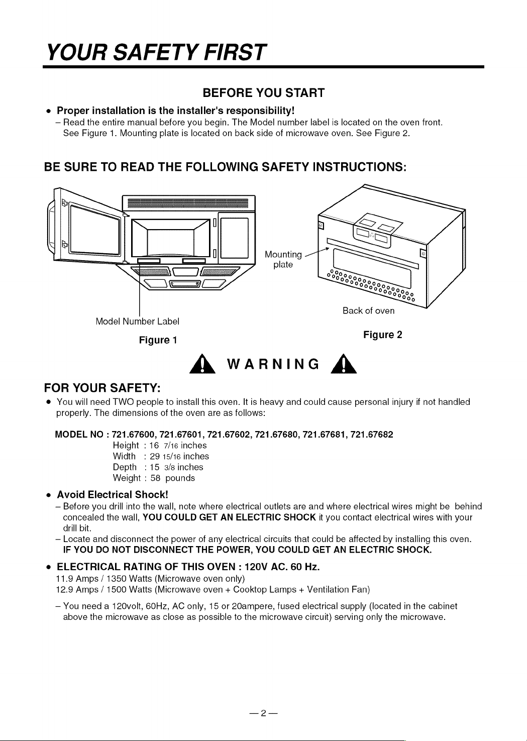
¢
Place
the
plug
into
a
properly
installed
and
grounded
outlet.
See
Figure
3.
«
Do
not
use
an
extension
cord.
PROPERLY
POLARIZED
AND
«
Keep
the
power
cord
dry
and
do
not
pinch
or
crush
it.
GROUNDED
OUTLET
e
DO
NOT,
UNDER
ANY
CIRCUMSTANCES,
REMOVE
THE
—
POWER
SUPPLY
CORD
GROUNDING
PRONG!
This
appliance
MUST
be
grounded!
Three-Pronged
(Grounding)
plug
Figure
3
A
WARNING
&
If
you
use
the
grounding
plug
improperly,
you
risk
electric
shock!
—
Check
with
a
qualified
electrician
if
you
are
not
sure
whether
the
oven
is
properly
grounded
or
if
you
do
not
completely
understand
the
grounding
instructions.
DO
NOT
USE
A
FUSE
IN
THE
NEUTRAL
OR
GROUNDING
CIRCUIT.
A
WARNING
&
Improper
grounding
could
result
in
electric
shock
or
other
personal
injury.
SAVE
THESE
INSTRUCTIONS
FOR
THE
LOCAL
ELECTRICAL
INSPECTOR'S
USE.
@
DO
NOT
EXPOSE
YOURSELF
TO
EXCESSIVE
MICROWAVE
ENERGY!
—
DO
NOT
try
to
operate
the
microwave
oven
with
the
door
open.
—
DO
NOT
tamper
with
or
defeat
the
safety
interlocks.
—
DO
NOT
place
objects
between
the
microwave
oven
front
face
and
the
door.
—
DO
NOT
allow
soil
or
cleaner
residue
to
build
up
on
the
flat
surfaces
around
the
microwave
oven
door.
—
DO
NOT
operate
the
microwave
oven
if it
is
damaged.
—
The
microwave
oven
door
must
close
properly
to
operate
safely.
~
DO
NOT
USE
THE
MICROWAVE
OVEN:
@
If
the
door
is
bent.
e
|f
the
hinges
or
latches
are
broken
or
loose.
e
If
the
door
seals,
sealing
surfaces
or
glass
is
broken.
~
DO
NOT
ATTEMPT
TO
ADJUST
OR
REPAIR
THE
OVEN
YOURSELF!
It
should
be
adjusted
and
repaired
by
a
qualified
technician
who
can
check
for
microwave
leakage
after
repairing
the
oven.
A
WARNING
&
If
you
do
not
use
the
microwave
oven
as
instructed,
you
could
be
exposed
to
excessive
microwave
energy.
YOUR
SAFETY
FIRST
e
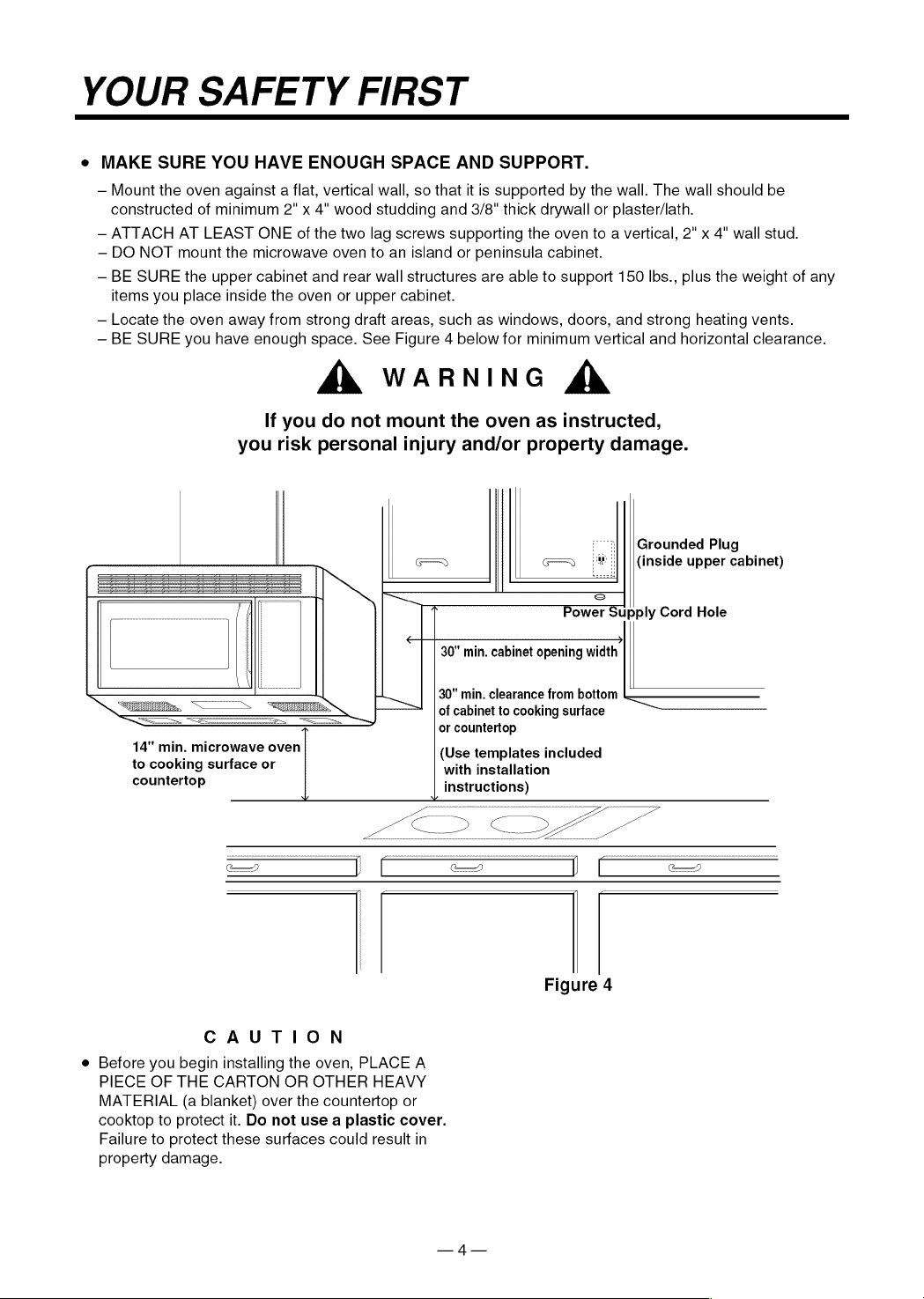
MAKE
SURE
YOU
HAVE
ENOUGH
SPACE
AND
SUPPORT.
—
Mount
the
oven
against
a
flat,
vertical
wall,
so
that
it
is
supported
by
the
wall.
The
wall
should
be
constructed
of
minimum
2"
x
4"
wood
studding
and
3/8"
thick
drywall
or
plaster/lath.
—
ATTACH
AT
LEAST
ONE
of
the
two
lag
screws
supporting
the
oven
to
a
vertical,
2"
x
4"
wall
stud.
~—
DO
NOT
mount
the
microwave
oven
to
an
island
or
peninsula
cabinet.
—
BE
SURE
the
upper
cabinet
and
rear
wall
structures
are
able
to
support
150
Ibs.,
plus
the
weight
of
any
items
you
place
inside
the
oven
or
upper
cabinet.
—
Locate
the
oven
away
from
strong
draft
areas,
such
as
windows,
doors,
and
strong
heating
vents.
~
BE
SURE
you
have
enough
space.
See
Figure
4
below
for
minimum
vertical
and
horizontal
clearance.
A
WARNING
&
If
you
do
not
mount
the
oven
as
instructed,
you
risk
personal
injury
and/or
property
damage.
Grounded
Plug
(inside
upper
cabinet)
Power
Supply
Cord
Hole
30"
min.
cabinet
opening
width
30"
min.
clearance
from
bottom
——
of
cabinet
to
cooking
surface
or
countertop
14"
min.
microwave
oven
(Use
templates
included
to
cooking
surface
or
with
installation
countertop
instructions)
Figure
4
CAUTION
e
Before
you begin
installing
the
oven,
PLACE
A
PIECE
OF
THE
CARTON
OR
OTHER
HEAVY
MATERIAL
(a
blanket)
over
the
countertop
or
cooktop
to
protect
it.
Do
not
use
a
plastic
cover.
Failure
to
protect
these
surfaces
could
result
in
property
damage.
PARTS,
TOOLS,
MATERIALS
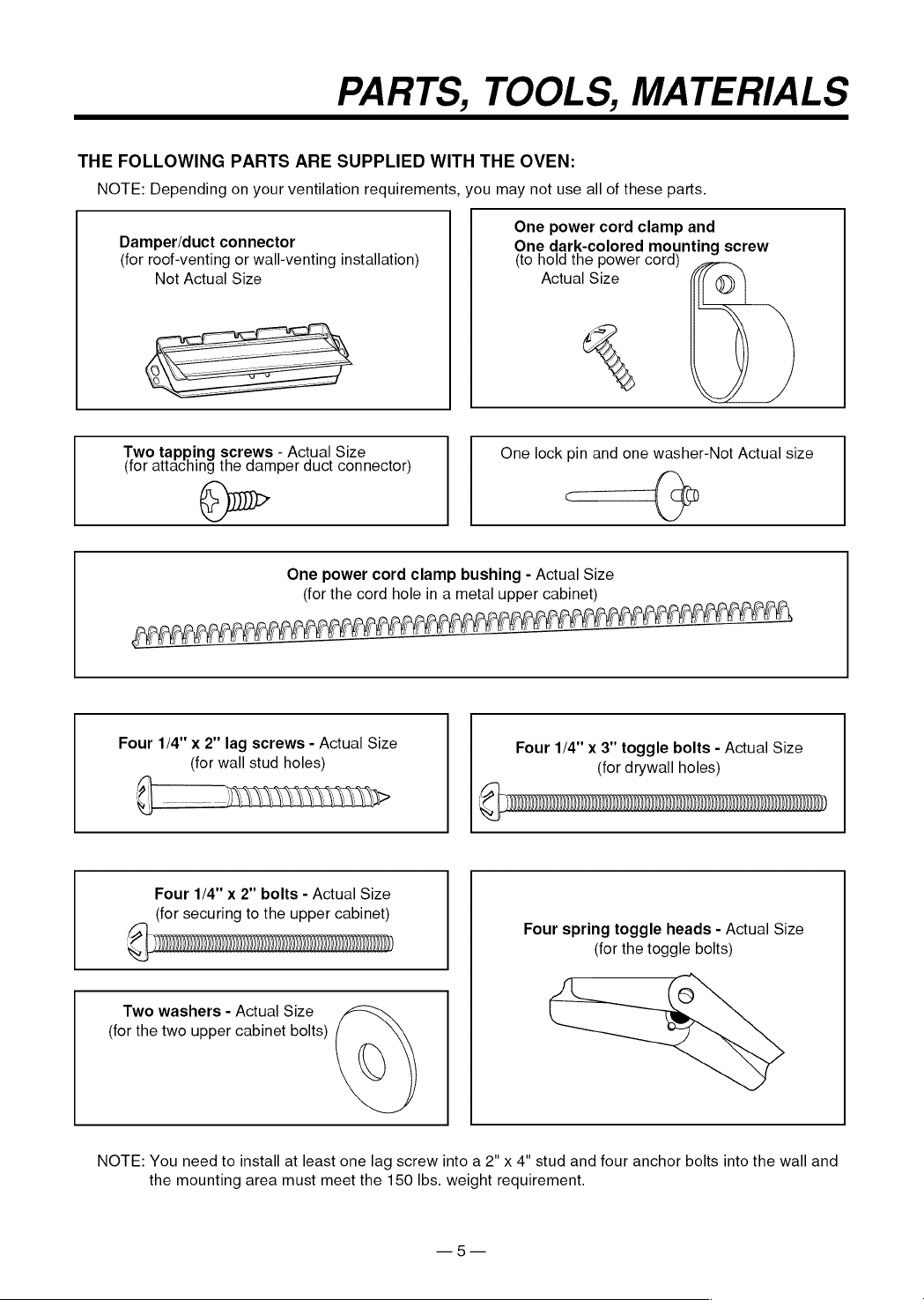
THE
FOLLOWING
PARTS
ARE
SUPPLIED
WITH
THE
OVEN:
NOTE:
Depending
on
your
ventilation
requirements,
you
may
not
use
all
of
these
parts.
One
power
cord
clamp
and
Damper/duct
connector
One
dark-colored
mounting
screw
(for
roof-venting
or
wall-venting
installation)
(to
hold
the
power
cord)
Not
Actual
Size
Actual
Size
%
|
|
Two
tapping
screws
-
Actual
Size
One
lock
pin
and
one
washer-Not
Actual
size
(for
attaching
the
damper
duct
connector)
@u~
=
One
power
cord
clamp
bushing
-
Actual
Size
(for
the
cord
hole
in
a
metal
upper
cabinet)
APE
>
LAS
ALAA
f
LA FA
LAL
AGAR
ME
EM
PERO
Ber
Ege
Four
1/4"
x
2"
lag
screws
-
Actual
Size
Four
1/4"
x
3"
toggle
bolts
-
Actual
Size
(for
wall
stud
holes)
(for
drywall
holes)
Four
1/4"
x
2"
bolts
-
Actual
Size
(for
securing
to
the
upper
cabinet)
@
|
opsenanpemnmnnmnenmnmmmmsemnninNTNT
Four
spring
toggle
heads
-
Actual
Size
CL
(for
the
toggle
bolts)
Two
washers
-
Actual
Size
(for
the
two
upper
cabinet
bolts)
NOTE:
You
need
to
install
at
least
one
lag
screw
into
a
2"
x
4"
stud
and
four
anchor
bolts
into
the
wall
and
the
mounting
area
must
meet
the
150
lbs.
weight
requirement.

PARTS,
TOOLS,
MATERIALS
YOU
WILL
NEED
THE
FOLLOWING
TOOLS
AND
MATERIALS
FOR
THE
INSTALLATION:
Carton
or
other
heavy
material
for
covering
the
counter
top.
Clear
tape
(for
taping
the
templates
to
the
wall)
Stud
finder
or
thin
nail.
Saber
saw
(for
cutting
vent
hloes
for
roof
or
wall
venting)
Phillips
screwdriver
(for
the
screws)
Pencil
Key
hole
saw
(for
the
power
cord
hole)
Electric
drill
3/8"
and
3/4"
wood
drill
bits
1/2"
and
3/16"
drill
bits
Flat
blade
screwdriver
(for
the
bolts)
Plumb
line
Measuring
tape
(metal
preferred)
Duct
Tape
Small
side
cutters
or
tin
snips
Caulking
gun
e
if
you
have
brick
or
masonry
walls,
you
need
special
hardware
and
tools.
e@
The
ductwork
you
need
for
the
installation
is
not
included.
All
wall
and
roof
caps
must
have
a
back-draft
damper.
STEP
17:
PREPARE
THE
ELECTRICAL
CONNECTIONS
A
WARNING
&
AVOID
ELECTRICAL
SHOCK!
THIS
APPLIANCE
MUST
BE
GROUNDED!
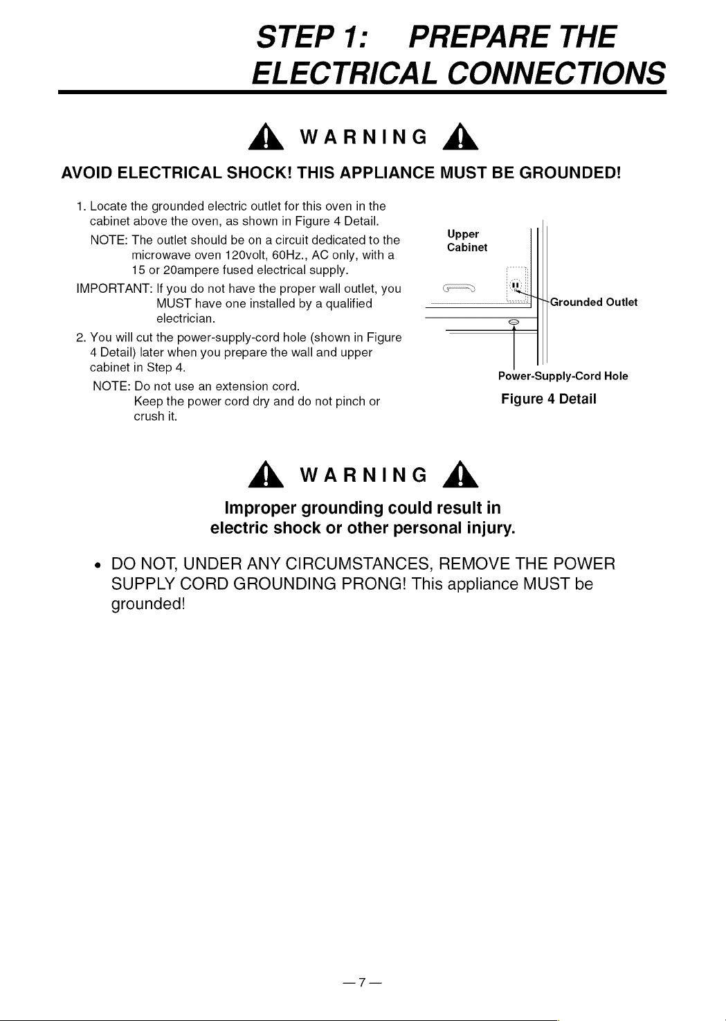
1.
Locate
the
grounded
electric
outlet
for
this
oven
in
the
cabinet
above
the
oven,
as
shown
in
Figure
4
Detail.
NOTE:
The
outlet
should
be
on
a
circuit
dedicated
to
the
microwave
oven
120volt,
60Hz.,
AC
only,
with
a
15
or
20ampere
fused
electrical
supply.
IMPORTANT:
If
you
do
not
have
the
proper
wall
outlet,
you
MUST
have
one
installed
by
a
qualified
electrician.
2.
You
will
cut
the
power-supply-cord
hole
(shown
in
Figure
4
Detail)
later
when
you
prepare
the
wall
and
upper
cabinet
in
Step
4.
NOTE:
Do
not
use
an
extension
cord.
Keep
the
power
cord
dry
and
do
not
pinch
or
crush
it.
Upper
Cabinet
Grounded
Outlet
A
WARNING
&
Improper
grounding
could
result
in
electric
shock
or
other
personal
injury.
Power-Supply-Cord
Hole
Figure
4
Detail
e
DO
NOT,
UNDER
ANY
CIRCUMSTANCES,
REMOVE
THE
POWER
SUPPLY
CORD
GROUNDING
PRONG!
This
appliance
MUST
be
grounded!
STEP
2:
PREPARE
THE
VENTING
SYSTEM
NOTE:
The
ductwork
you
need
for
outside
ventilation
is
not
included
with
your
oven.
The
standard
ductwork
fittings
and
length
Sears
recommends
are
shown
in
Figure
9,
page
9.
AX
WARNING-FIRE
HAZARD
ZY
THIS
OVEN
MUST
BE
PROPERLY
VENTED!
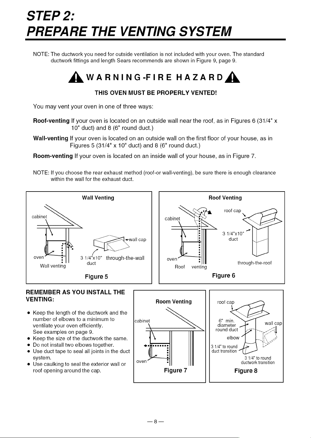
You
may
vent
your
oven
in
one
of
three
ways:
Roof-venting
If
your
oven
is
located
on an
outside
wall
near
the
roof,
as
in
Figures
6
(31/4"
x
10"
duct)
and
8
(6"
round
duct.)
Wall-venting
lf
your
oven
is
located
on an
outside
wall
on
the
first
floor
of
your
house,
as
in
Figures
5
(31/4"
x
10”
duct)
and
8
(6"
round
duct.)
Room-venting
If
your
oven
is
located
on an
inside
wall
of
your
house,
as
in
Figure
7.
NOTE:
If
you
choose
the
rear
exhaust
method
(roof-or
wall-venting),
be
sure
there
is
enough
clearance
within
the
wall
for
the
exhaust
duct.
Wall
Venting
Roof
Venting
ek
roof
cap
cabinet
cabinet
a
3
1/4"x10"
duct
i
oven
3
1/4"x10"
through-the-wall
oven
Wall
venting
duct
Roof
venting
through-the-roof
Figure
5
Figure
6
REMEMBER
AS
YOU
INSTALL
THE
VENTING:
Room
Venting
roof
cap
e
Keep
the
length
of
the
ductwork
and
the
number
of
elbows
to
a
minimum
to
cabinet
6”
min.
ventilate
your
oven
efficiently.
diameter
.
wall
cap
See
examples
on
page
9.
\
round
duct
fy
All
e
Keep
the
size
of
the
ductwork
the
same.
;
elbow
~|
K
2
e
Do
not
install
two
elbows
together.
nfeereees
3
1/4"
to
round
oe
e
Use
duct
tape
to
seal
all
joints
in
the
duct
:
duct
transition
system.
2
3
1/4"
to
round
e
Use
caulking
to
seal
the
exterior
wall
or
|
°Y°"
.
ductwork
transition
roof
opening
around
the
cap.
Figure
7
Figure
8
STEP
2:
PREPARE
THE
VENTING
SYSYTEM
STANDARD
FITTINGS
NOTE:
If
the
existing
duct
is
round,
you
must
use
a
rectangular-to-round
adapter,
with
a
rectangular
3"
extension
duct
installed
between
the
damper
assembly
and
the
adapter
to
prevent
the
exhaust
damper
sticking.
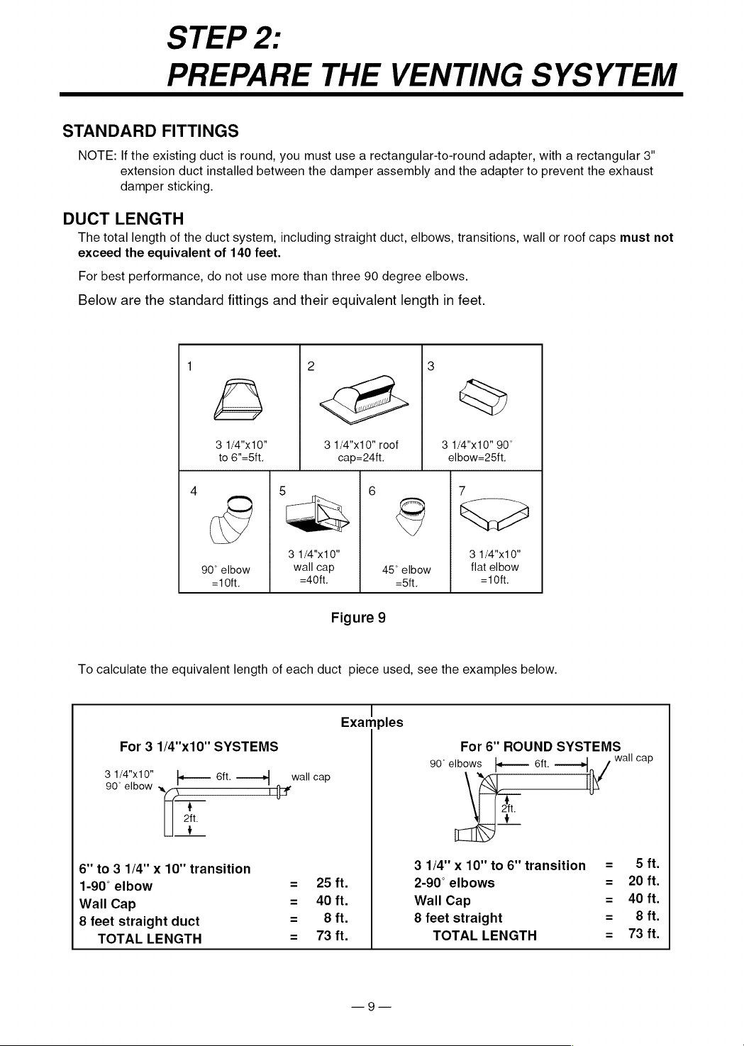
DUCT
LENGTH
The
total
length
of
the
duct
system,
including
straight
duct,
elbows,
transitions,
wall
or
roof
caps
must
not
exceed
the
equivalent
of
140
feet.
For
best
performance,
do
not
use
more
than three
90
degree
elbows.
Below
are
the
standard
fittings
and
their
equivalent
length
in
feet.
1
3
3
1/4"x10"
3
1/4"x10"
roof
3
1/4"x10"
90°
to
6"=5ft.
cap=24tt.
elbow=25ft.
4
5
1
6
7
3
1/4"x10"
3
1/4"x10"
90°
elbow
wail
cap
45°
elbow
flat
elbow
-10ft. =40ft.
-5ft.
=10ft.
Figure
9
To
calculate
the
equivalent
length
of
each
duct
piece
used,
see
the
examples
below.
|!
Examples
For
3
1/4"x10"
SYSTEMS
For
6"
ROUND
SYSTEMS
i
90°
elbows
j}-——
6ft.
——»
wali
cap
3
1/4"x10"
ft.
90°
elbow
«
k—
Bit.
——>|
_wall
cap
iN
4
aft.
'
6"
to
3
1/4"
x
10"
transition
31/4"x10"to6"
transition
=
Sft.
1-90°
elbow
=
25ft.
2-90°
elbows
=
20
ft.
Wall
Cap
=
A0ft.
Wall
Cap
=
40
ft.
8
feet
straight
duct
=
68ft.
8
feet
straight
=
68fit.
TOTAL
LENGTH
=
73
ft.
TOTAL
LENGTH
=
73
ft.
STEP
3:
PREPARE
THE
VENTING
BLOWER
Your
microwave
oven
is
shipped
with
the
blower
assembled
for
roof
venting.
You
need
to
adjust
the
blower
if
you
want
wall-venting
or
room-vented
(recirculating)
installation.
A
WARNING
&
ELECTRICAL
SHOCK
HAZARD!
e
DO
NOT
PULL
OR
STRETCH
THE
BLOWER
WIRING!
Pulling
and
stretching
the
blower
wiring
could
result
in
electrical
shock.
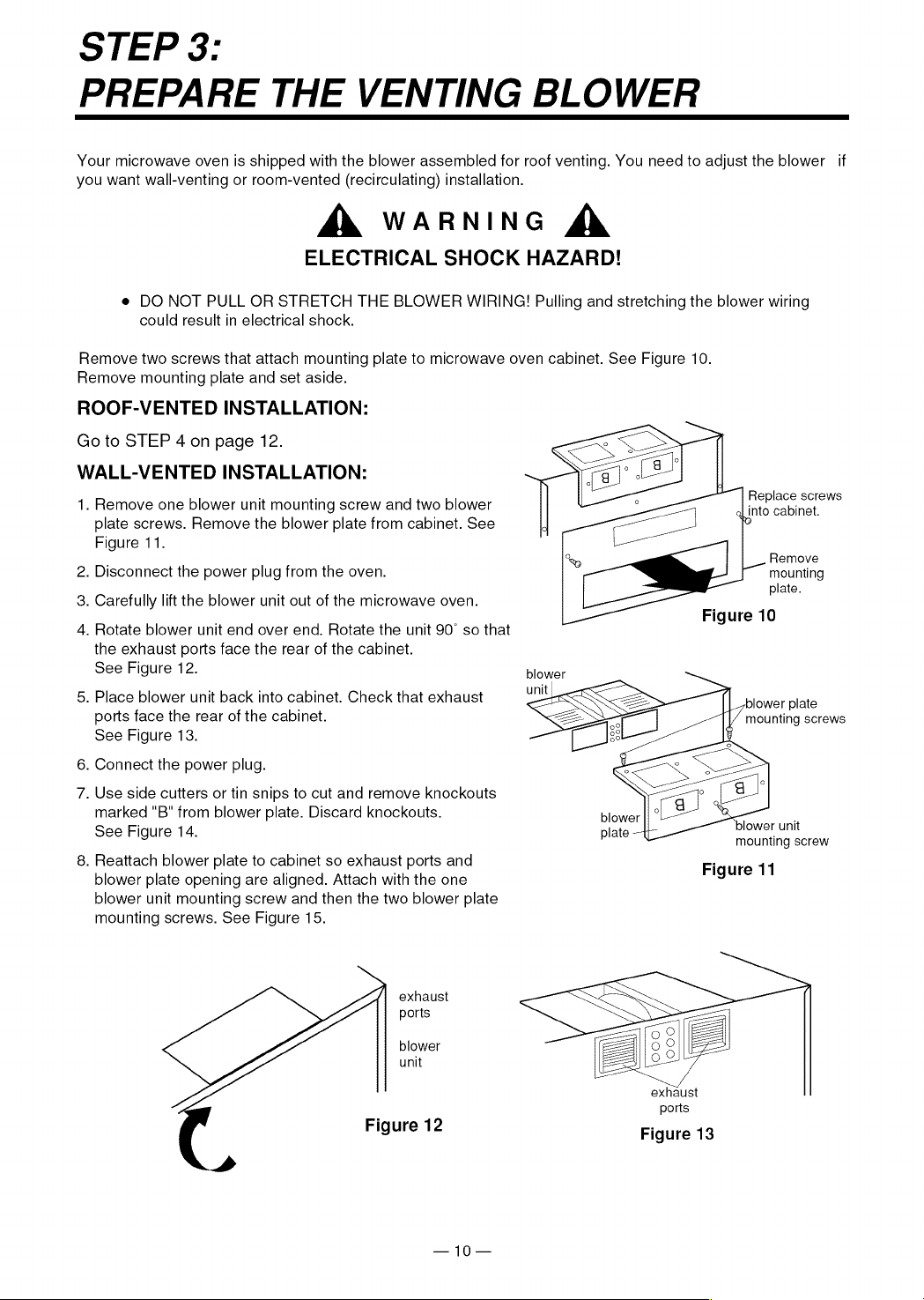
Remove
two
screws
that
attach
mounting
plate
to
microwave
oven
cabinet.
See
Figure
10.
Remove
mounting
plate
and
set
aside.
ROOF-VENTED
INSTALLATION:
Go
to
STEP
4
on
page
12.
WALL-VENTED
INSTALLATION:
1.
Remove
one
blower
unit
mounting
screw
and
two
blower
plate
screws.
Remove
the
blower
plate
from
cabinet.
See
Figure
11.
Replace
screws
aL
into
cabinet.
0
.
Remove
2.
Disconnect
the
power
plug
from
the
oven.
mounting
: : .
plate.
3.
Carefully
lift
the
blower
unit
out
of
the
microwave
oven.
:
; oo.
Figure
10
4.
Rotate
blower
unit
end
over
end.
Rotate
the
unit
90°
so
that
the
exhaust
ports
face
the
rear
of
the
cabinet.
See
Figure
12.
blower
5,
Place
blower
unit
back
into
cabinet.
Check
that
exhaust
unit
blower
plate
ports
face
the
rear
of
the
cabinet.
See
Figure
13.
mounting
screws
6.
Connect
the
power
plug.
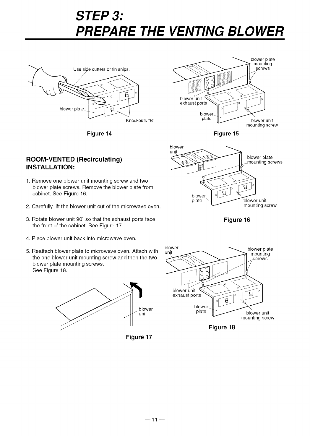
7.
Use
side
cutters
or
tin
snips
to
cut
and
remove
knockouts
marked
“B"
from
blower
plate.
Discard
knockouts.
See
Figure
14.
plate
-
blower
unit
mounting
screw
8.
Reattach
blower
plate
to
cabinet
so
exhaust
ports
and
blower
plate
opening
are
aligned.
Attach
with
the
one
blower
unit
mounting
screw
and
then
the
two
blower
plate
mounting
screws.
See
Figure
15.
Figure
11
exhaust
ports
blower
unit
exhaust
ports
Figure
12
Figure
13
—10—
STEP
3:
PREPARE
THE
VENTING
BLOWER
blower
plate
mounting
screws
Use
side
cutters
or
tin
snips.
blower
unit
exhaust
ports
blower
unit
mounting
screw
Knockouts
"B"
Figure
14
Figure
15
blower
unit
blower
plate
mounting
screws
ROOM-VENTED
(Recirculating)
INSTALLATION:
1.
Remove
one
blower
unit
mounting
screw
and
two
blower
plate
screws.
Remove
the
blower
plate
from
cabinet.
See
Figure
16.
2.
Carefully
lift
the
blower
unit
out
of
the
microwave
oven.
mounting
screw
3.
Rotate
blower
unit
90°
so
that
the
exhaust
ports
face
Figure
16
the front
of
the
cabinet.
See
Figure
17.
4.
Place
blower
unit
back
into
microwave
oven.
blower
5.
Reattach
blower
plate
to
microwave
oven.
Attach
with
—
ynit
Sentra.
the
one
blower
unit
mounting
screw
and
then
the
two
screws
blower
plate
mounting
screws.
See
Figure
18.
blower
unit
exhaust
ports
blower
blower
unit
plate
blower
unit
mounting
screw
Figure
18
Figure
17
—11—
STEP
4:
PREPARE
THE
WALL
AND
UPPER
CABINET
FOR
INSTALLATION
BEFORE
YOU
START
1.
Remove
any
shipping
materials
and
parts
from
inside
the
microwave
oven.
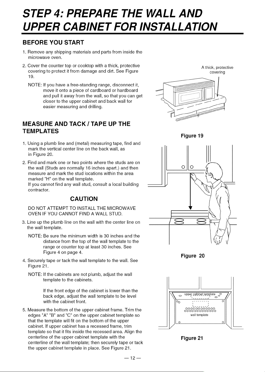
2.
Cover
the
counter
top
or
cooktop
with
a
thick,
protective
covering
to
protect
it
from
damage
and
dirt.
See
Figure
19.
NOTE:
If
you
have
a
free-standing
range,
disconnect
it,
move
it
onto
a
piece
of
cardboard
or
hardboard
and
pull
it
away
from
the
wall,
so
that
you
can
get
closer
to
the
upper
cabinet
and
back
wall
for
easier
measuring
and
drilling.
MEASURE
AND
TACK
/
TAPE
UP
THE
TEMPLATES
1.
Using
a
plumb
line
and
(metal)
measuring
tape,
find
and
mark
the
vertical
center
line
on
the
back
wall,
as
in
Figure
20.
2.
Find
and
mark
one
or
two
points
where
the
studs
are
on
the
wall
(Studs
are
normally
16
inches
apart.)
and
then
measure
and
mark
the
stud
locations
within
the
area
marked
"H"
on
the
wall
template.
If
you
cannot
find
any
wall
stud,
consult
a
local
building
contractor.
CAUTION
DO
NOT
ATTEMPT
TO
INSTALL
THE
MICROWAVE
OVEN
IF
YOU
CANNOT
FIND
A
WALL
STUD.
3.
Line
up
the
plumb
line
on
the
wall
with
the
center
line
on
the
wall
template.
NOTE:
Be
sure
the
minimum
width
is
30
inches
and
the
distance
from
the
top
of
the
wall
template
to
the
range
or
counter
top
at
least
30
inches.
See
Figure
4
on
page
4.
4.
Securely
tape
or
tack
the
wall
template
to
the
wall.
See
Figure
21.
NOTE:
If
the
cabinets
are
not
plumb,
adjust
the
wall
template
to
the
cabinets.
If
the
front
edge
of
the
cabinet
is
lower
than
the
back
edge,
adjust
the
wall
template
to
be
level
with
the
cabinet
front.
5.
Measure
the
bottom
of
the
upper
cabinet
frame.
Trim
the
edges
"A" "B"
and
“C"
on
the
upper
cabinet
template
so
that
the
template
will
fit
on
the
bottom
of
the
upper
cabinet.
If
upper
cabinet
has
a
recessed
frame,
trim
template
so
that
it
fits
inside
the
recessed
area. Align
the
centerline
of
the
upper
cabinet
template
with
the
centerline
of
the
wall
template;
then
securely
tape
or
tack
the
upper
cabinet
template
in
place.
See
Figure
21.
—12—
A
thick,
protective
covering
Figure
20
QD
upper
cabinet
template
©
<
oe
2
SSS
°
s-
i
-
~
0
Figure
21

STEP
4:
PREPARE
THE
WALL
AND
UPPER
CABINET
FOR
INSTALLATION
DRILL
THE
HOLES
IN
THE
WALL
AND
UPPER
CABINET.
as
.
Cut
or
drilla
"2"
diameter
hole
at
the
area
marked
"M",
.
Cut
out
the
venting
areas
(with
the
saber
saw):
.
Complete
whichever
venting
system
you
have
chosen.
Use
A
WARNING
&
BE
VERY
CAREFUL
WHEN
DRILLING
HOLES
INTO
THE
WALL.
Electrical
wires
could
be
concealed
behind
the
wall
covering
and
if
the
drill
hits
them
you
could
get
an
electric
shock.
.
Find
the
points
on
the
wall
template
labeled
"D",
“E",
"F",
and
"G".
Drill
a
3/16"
diameter
hole
at
any
points
that
are
over
a
wall
stud.
Drill
a
3/4"
diameter
hole
at
any
points
over
drywall.
.
Locate
the
wall
stud
closest
to
the
center
of
the
areas
marked
“H"
and
“I”
on
the
wall
template.
Drill
3/16"
holes
into
the
wall
stud
in
each
of
the
areas.
If
a
wall
stud
is
not
located
within
these
areas,
drill
3/4"
diameter
holes
nearest
to
the
center
of
the
areas
as
possible.
If
there
is
not
a
wall
stud
within
the
areas
marked
"H"
and
"I"
and
not
behind
points
marked
"D",
"E",
"F"
and
"G",
DO
NOT
install
microwave
oven.
(Consult
building
inspector.)
.
Drill
a
3/8"
hole
at
points
"J",
"K"
and
"N"
on
the
upper
cabinet
template.
NOTE:
If
the
bottom
of
the
upper
cabinet
is
recessed
3/4"
or
more,
you
will
need
2"x2"
filler
blocks
(not
included)
to
provide
additional
support
for
the
bolts.
See
Figure
22.
-
Mark
the
center
of
each
filler
block
and
drill a
3/8"
diameter
hole
at
the
marks.
«
Align
filler
blocks
over
the
two
openings
in
the
top
of
the
microwave
oven
cabinet
and
attach
to
cabinet
with
masking
tape.
See
Figure
23.
filler
block
cabinet
bottom
shelf
cabinet
front
“Power-supply-cord-hole”
on
the
upper
cabinet
template.
If
the
upper
cabinet
is
metal,
you
will
need
to
cover
the
edge
of
the
hole
with
the
power-supply-cord
bushing
(supplied)
to
prevent
damage
to
the
cord
from
the
rough
metal
edge.
A
WARNING
&
YOU
MUST
COVER
THE
EDGE
OF
THE
POWER-
SUPPLY-CORD-HOLE
IN
A
METAL
CABINET
WITH
THE
POWER-SUPPLY-CORD
BUSHING.
FAILURE
TO
DO
SO
COULD
RESULT
IN
DAMAGE
TO
THE
CORE
AND
ELECTRIC
SHOCK.
Figure
22
e
Roof-Vented-cut
out
the
shaded
area
marked
"L"
on
the
upper
cabinet
template.
e
Wall-Vented-cut
out the
shaded
area
marked
"O"
on
the
wall
template.
e
Room-Vented-go
to
STEP
5,
INSTALLING
THE
MOUNTING
PLATE,
located
on
the
next
page.
filler
block
caulking
compound
to
seal
the
exterior
wall
or
roof
opening
around
the
wall
cap
or
roof
cap.
Figure
23
—13—
STEP
5:
INSTALL
THE
MOUNTING
PLATE
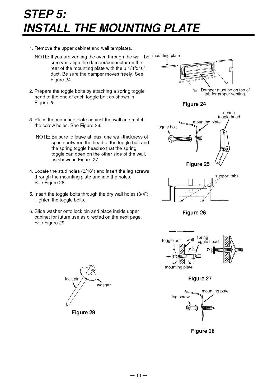
1.
Remove
the
upper
cabinet
and
wall
templates.
NOTE:
If
you
are
venting
the
oven
through
the
wall,
be
™ounting
plate
sure
you
align the
damper/connector
on
the
rear
of
the
mounting
plate
with
the
3
1/4"x10"
duct.
Be
sure
the
damper
moves
freely.
See
Figure
24.
2.
Prepare
the
toggle
bolts
by
attaching
a
spring
toggle
&
Damper
must
be on
top
of
head
to
the
end
of
each
toggle
bolt
as
shown
in
prop
g
Figure
25.
Figure
24
spring
toggle
head
3.
Place
the
mounting
plate
against
the
wall
and
match
:
Sn
plate
the
screw
holes.
See
Figure
26.
toggle
bolt
|
NOTE:
Be
sure
to
leave
at
least
one
wall-thickness
of
space
between
the
head
of
the
toggle
bolt
and
the
spring toggle
head
so
that
the
spring
toggle
can
open
on
the
other
side
of
the
wall,
as
shown
in
Figure
27.
i
4.
Locate
the
stud
holes
(3/16")
and
insert
the
lag
screws
through
the
mounting
plate
and
into
the
holes.
See
Figure
28.
5.
Insert
the
toggle
bolts
through
the dry
wall
holes
(3/4").
Tighten
the
toggle
bolts.
6.
Slide
washer
onto
lock
pin
and
place
inside
upper
Figure
26
cabinet
for
future
use
as
directed
on
the
next
page.
See
Figure
29.
el
toggle
bolt
wall
Sale
head
mounting
plate.
lock
pin
~
Figure
27
\
washer
mounting
pate
lag
screw
Y
X
eo
Figure
29
Figure
28
—14—
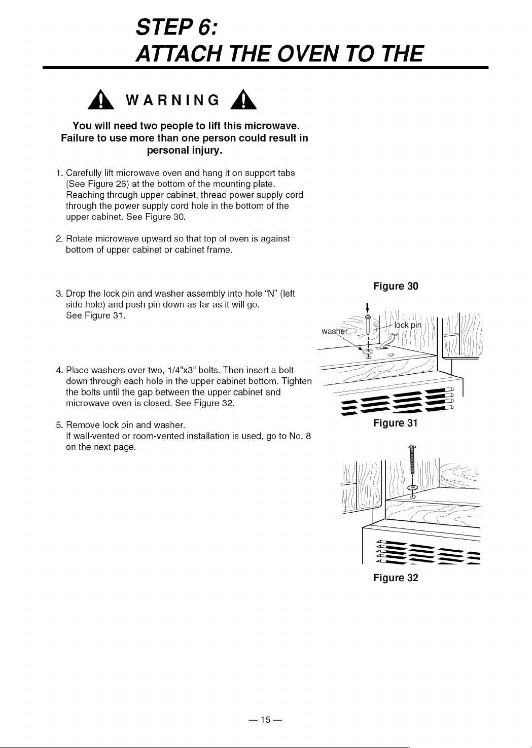
STEP
6:
ATTACH
THE
OVEN
TO
THE
A
WARNING
&
You
will
need
two
people
to
lift
this
microwave.
Failure
to
use
more
than
one
person
could
result
in
personal
injury.
.
Carefully
lift
microwave
oven
and
hang
it
on
support
tabs
(See
Figure
26)
at
the
bottom
of
the
mounting
plate.
Reaching
through upper
cabinet,
thread
power
supply
cord
through
the
power
supply
cord
hole
in
the
bottom
of
the
upper
cabinet.
See
Figure
30.
.
Rotate
microwave
upward
so
that
top
of
oven
is
against
bottom
of
upper
cabinet
or
cabinet
frame.
Figure
30
.
Drop
the
lock
pin
and
washer
assembly
into
hole
“N”
(left
g
side
hole)
and
push
pin
down
as
far
as
it
will
go.
See
Figure
31.
.
Place
washers
over
two,
1/4"x3"
bolts.
Then
insert
a
bolt
down
through
each
hole
in
the
upper
cabinet
bottom.
Tighten
the bolts
until
the
gap
between
the
upper
cabinet
and
microwave
oven
is
closed.
See
Figure
32.
.
Remove
lock
pin
and
washer.
If
wall-vented
or
room-vented
installation
is
used,
go
to
No.
8
on
the
next
page.
Figure
32
—15—
STEP
6:
ATTACH
THE
OVEN
TO
THE
WALL
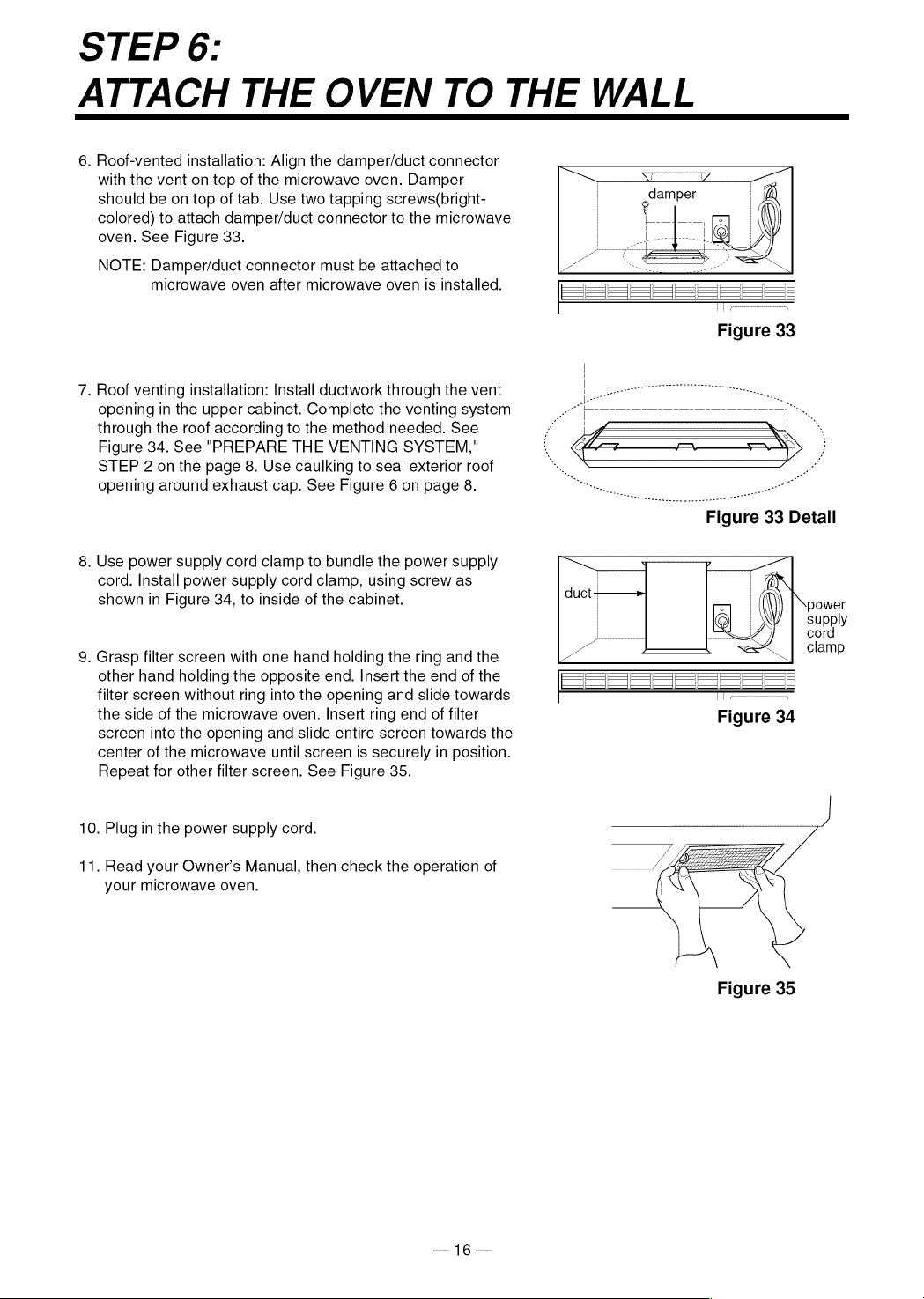
6.
Roof-vented
installation:
Align
the
damper/duct
connector
with
the
vent
on
top
of
the
microwave
oven.
Damper
should
be
on
top
of
tab.
Use
two
tapping
screws(bright-
goampet
colored)
to
attach
damper/duct
connector
to
the
microwave
|
oven.
See
Figure
33.
os
ee
NOTE:
Damper/duct
connector
must
be
attached
to
microwave
oven
after
microwave
oven
is
installed.
7.
Roof
venting
installation:
Install
ductwork
through
the
vent
opening
in
the
upper
cabinet.
Complete
the
venting
system
PO
a
i,
through
the
roof
according
to
the
method
needed.
See
f
JS
*
Figure
34.
See
"PREPARE
THE
VENTING
SYSTEM,"
i
oceans
MN
eo-o~eeoo>eooooaowv
STEP
2
on
the
page
8.
Use
caulking
to
seal
exterior
roof
opening
around
exhaust
cap.
See
Figure
6
on
page
8.
8.
Use
power
supply
cord
clamp
to
bundle
the
power
supply
cord.
Install
power
supply
cord
clamp,
using
screw
as
shown
in
Figure
34,
to
inside
of
the
cabinet.
9.
Grasp
filter
screen
with
one
hand
holding
the
ring
and
the
other
hand
holding
the
opposite
end.
Insert
the
end
of
the
===]
SS
Se
filter
screen
without
ring
into
the
opening
and
slide
towards
7
the
side
of
the
microwave
oven.
Insert
ring
end
of
filter
Figure
34
screen
into
the
opening
and
slide
entire
screen
towards
the
center
of
the
microwave
until
screen
is
securely
in
position.
Repeat
for
other
filter
screen.
See
Figure
35.
10.
Plug
in
the
power
supply
cord.
LE
11.
Read
your
Owner’s
Manual,
then
check
the
operation
of
your
microwave
oven.
Figure
35
—
16—
SEARS
Installtion
Instructions
Model
No.
721.
67600
721.
67601
721.
67602
721.
67680
721.
67681
721.
67682
The
model
number
of
your
microwave
oven
is
found
on
the
front
face
of
the
cavity.
When
requesting
service,
always
provide
the
following
information:
*
Product
Type
*
Model
Number
*
Serial
Number
*
Problem
Description
Kenmore
§
MICROWAVE
OVEN
Aa,
For
in-house
major
brand
repair
service
Call
24
hours
a
day,
7
days
a
week
1-800-4-REPAIR
(ez
(1-800-473-7247)
Para
pedir
servicio
de
reparacion
a
(O
—{(O)
domicilio-
1-800-676-5811
For
the
location
a
Sears
Parts
and
Repair
Center
in
your
area
Call
24
hours
a
day,
7
days
a
week
1-800-488-1222
SEARS
For
information
on
purchasing
a
Sears
Maintenance
Agreement
or
to
inquire
about
an
existing
Agreement
Call
9
am-5
pm,
Monday-Saturday
1-800-827-6655
SEARS
America’s
Repair
Specialists
P/NO.:
3828W5U007
03/'97
Printed
in
Korea
Sears,
Roebuck
and
Co.,
Hoffman
Estates,
IL
60179
U.S.A.