Loading ...
SONANCE
|
OUTDOOR SPEAKERS MARINER
|
INSTRUCTION MANUAL 2
PRODUCT DESCRIPTION
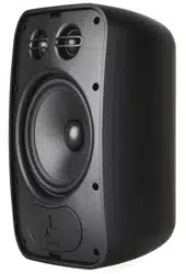
Thank you for purchasing Sonance Mariner weather-
resistant speakers.
When properly installed, these speakers will give you many
years of outdoor entertainment pleasure. To get the most out of
your new speakers, please read this manual thoroughly before
you begin installation.
The directions in this manual apply to the following models:
MARINER 54, MARINER 54 SST, MARINER 56, MARINER 64,
MARINER 64 SST, MARINER 66, and MARINER 86
BOX & CONTENTS
Sonance MARINER 54, MARINER 56, MARINER 64, MARINER 66, and
MARINER 86 2-Way speaker boxes contain: (2) Speakers, (2) Speaker
Grilles, (2) FastMount
®
Brackets, and (2) Wiring Terminal Covers.
Sonance MARINER 54 SST, and MARINER 64 SST, Single Stereo
speaker boxes contain: (1) Speaker, (1) Speaker Grille, (1) FastMount
®
Bracket, and (1) Wiring Terminal Cover.
TYPES OF WIRE
When installing Sonance
Mariner Outdoor Speakers
careful consideration should
be made when determining
speaker placement and
what guage wire should be
used. Please refer to the
wiring chart (see figure 2) to
determine which size wire to
use over the given distance
between the amplifier/
receiver and the speakers.
WIRE GAUGE CHART
18 Gauge Up to 100 feet (30 meters)
Up to 150 feet (45 meters)
Up to 250 feet (80 meters)
Up to 400 feet (122 meters)
Up to 650 feet (198 meters)
WIRE GAUGE DISTANCE
16 Gauge
14 Gauge
12 Gauge
10 Gauge
FIGURE 2: WIRE GAUGE CHART
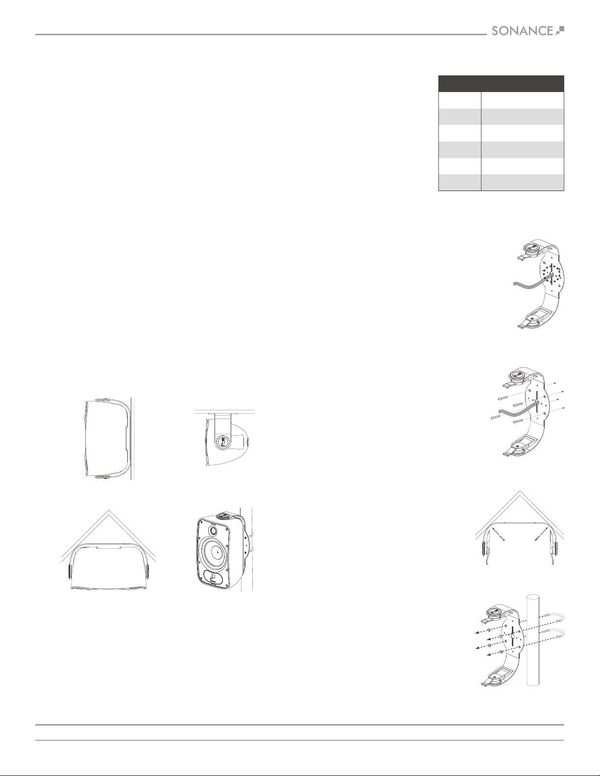
SPEAKER PLACEMENT
Mariner speakers are highly weather-resistant, and when mounted
outdoors will perform exceptionally well for years even under
adverse weather conditions.
The Mariner FastMount bracket system makes it easy to mount the
speakers in a variety of positions and locations: (see figure 1).
Under an eaveAgainst a wall
(flush)
In a corner
Pole mount
FIGURE 1:
SPEAKER PLACEMENT
The best performance is obtained by placing the speakers at ear
level, facing the listeners.
• If you are mounting the speakers above or below ear level, pivot
them up or down to direct the sound towards the listeners.
• You can orient the speakers either horizontally or vertically without
affecting the sound quality.
CONNECTING AND
ASSEMBLING THE SPEAKERS
WARNING: TURN THE AMPLIFIER’S POWER
OFF UNTIL YOU HAVE COMPLETED ALL OF
THE CONNECTIONS AND HAVE DETERMINED
THAT THEY ARE CORRECT. (IF THE AMP’S AC
PLUG IS ACCESSIBLE WE RECOMMEND THAT
YOU UNPLUG IT FROM THE WALL OUTLET TO
AVOID ACCIDENTAL TURN-ON AND POSSIBLE
DAMAGE TO THE AMPLIFIER.)
FIGURE 3:
PASS WIRE
THROUGH HOLE
1. In most cases you will be able to attach
the FastMount brackets directly to the
mounting surface. Run the speaker wires
from the amplifier to the speaker locations
and through the holes in the brackets and
mounting bases, if used (see figure 3).
NOTE: TO INCREASE WATER RESISTANCE AND
MAKE INSTALLATION EASIER, THE SPEAKER
WIRE TERMINALS ARE LOCATED ON THE
MARINER SPEAKERS’ FRONT PANEL. BE SURE
TO LEAVE ENOUGH WIRE AT THE SPEAKER
LOCATION TO FEED THROUGH THE TUNNEL
IN THE SPEAKER ENCLOSURE AND CONNECT
TO THE TERMINALS ON THE FRONT.
FIGURE 4:
ATTACH BRACKET
2. Attach the FastMount brackets to the
mounting surface using hardware
(not included) that is appropriate for
the type of surface (see figure 4).
FIGURE 5:
CORNER MOUNTING
• If the installation requires that the
speaker be mounted in a corner,
attach the bracket with hardware
through the slots in the angled
corners (see figure 5).
3. If the installation requires that the
speaker be mounted on a pole you
can attach the FastMount brackets
to the pole using 2.5” U-bolts
(not included) (see figure 6).
FIGURE 6:
ATTACHING THE
BRACKET TO A POLE
Loading ...
Loading ...