User Guide
ENGLISH
Square Faceplate Digital Bluetooth Door Knob
Model 8832001S
8832101S
8832301S
8832401S
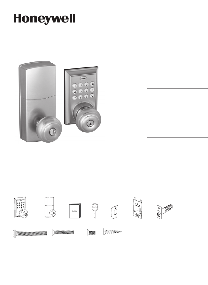
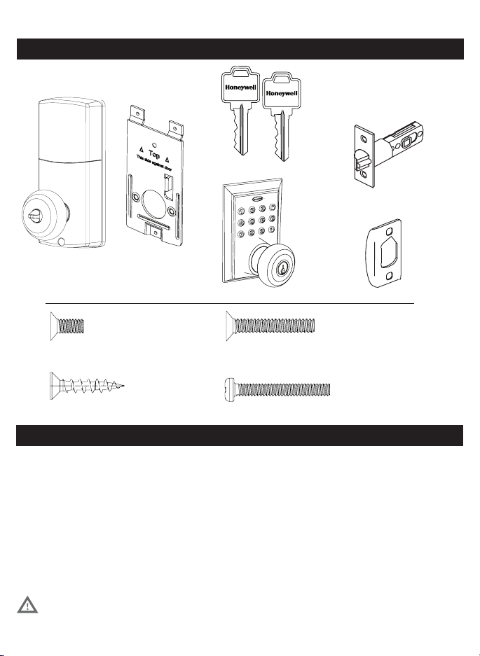
Package Includes:
1 - Exterior Faceplate
1 - Interior Faceplate
1 - User Guide
2 - Keys
1 - Strike Plate
1 - Mounting Plate
1 - Latch
1 - 1 3/8” Screws
2 - 5/16” Screws
2 - 1 “ Screws
5 - 3/4” Screws
Read this manual carefully before installing and operating!
Please carefully check the above list to confirm all items have been received. If any items are
missing, please contact Consumer Assistance. ( See page for contact information)
3/4” Screws1” Screws 5/16” Screws1 3/8” Screws
Exterior Faceplate Interior Faceplate User Guide Keys
Strike plate Latch
Mounting Plate

I. INSTALLATION INSTRUCTIONS
Product Overview / Tools Required.......................................................................................................... Page 1
Prepare Door and Jamb............................................................................................................................... Page 2
Adjusting And Installing Latch.................................................................................................................. Page 3
Installing Exterior Assembly...................................................................................................................... Page 4
Installing Interior Assembly....................................................................................................................... Page 56
II. MOBILE APPLICATION INSTRUCTIONS
Mobile App Installation & Use .................................................................................................................. Page 7
Connect to Lock / Lock Settings ............................................................................................................. Page 8
Lock and Unlock ........................................................................................................................................... Page 9
System Settings............................................................................................................................................. Page 10
Account Management/Notifications ..................................................................................................... Page 11
Send Passcodes and eKeys ........................................................................................................................ Page 12
Manage Users ................................................................................................................................................ Page 1315
III. PHYSICAL KEYPAD PROGRAMMING / TROUBLESHOOTING / ASSISTANCE / WARRANTY
Keypad Programming.................................................................................................................................. Page 16
Turn On/Off Auto Lock Function.............................................................................................................. Page 17
Sound Off......................................................................................................................................................... Page 17
Sound On......................................................................................................................................................... Page 17
Restore Factory Settings............................................................................................................................ Page 17
Add Administrator......................................................................................................................................... Page 18
Customize Passcodes Received from the App...................................................................................... Page 18
EnableDisable AutoLock......................................................................................................................... Page 18
Vacation Mode............................................................................................................................................... Page 18
Disable Vacation Mode................................................................................................................................ Page 18
IV. ASSISTANCE
Trouble Shooting............................................................................................................................................ Page 19
Template........................................................................................................................................................... Page 2021
Consumer Assistance.................................................................................................................................... Page 22
FCC COMPLIANCE......................................................................................................................................... Page 23
Warranty............................................................................................................................................................ Page 24
INDEX
1
PAY CLOSE ATTENTION TO ALERTS
INSTALLATION INSTRUCTIONS
Tools Required for Installation
on Doors That Require Drilling:
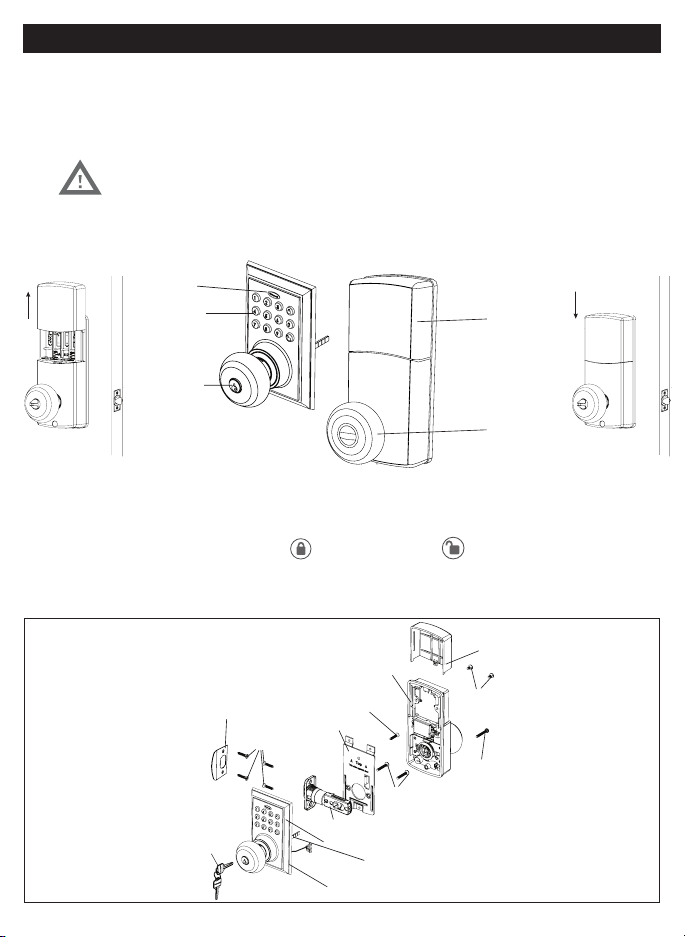
Interior Assembly
Exterior Assembly
Entry keys (2 ea.)
5/16” (8mm) Screws - 2 ea.
3/4” (19mm) Screws - 5 ea. 1” (25mm) Screw - 1 ea.
Strike Plate
Latch (Adjustable)
Tools Required for Installation on Pre-drilled Doors:
NOTE: DO NOT USE a drill.
Electronic lock requires (4) High Quality AA Alkaline
batteries. When all 4 batteries are installed in the
correct position, hear 2 beeps and the keypad will
keypad stops illuminating.
Batteries (not included)
PACKAGE CONTENTS
TOOLS REQUIRED
Mounting Plate
2
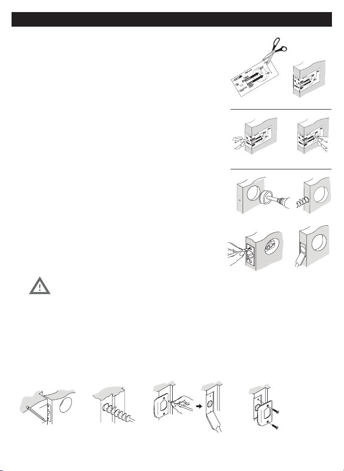
NOTE: For installation on doors with pre-drilled holes skip to page 4.
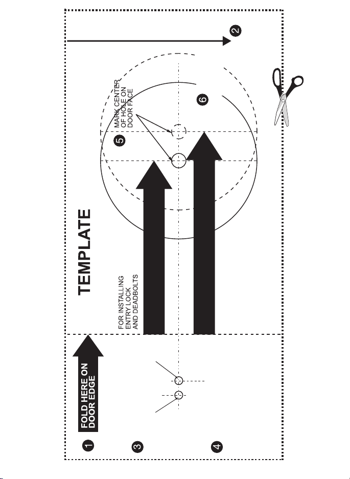
1. TEMPLATE
(Figure 1a).
b. Fold template and place on door 36” (915mm) from
the ground as marked (Figure 1b).
2. MARK THE DOOR FOR DRILLING
b. Mark center hole on door edge through guide on
template for 1” (25mm) latch bolt (Figure 2a).
a. Mark center hole on door face through guide on
backset (Figure 2b).
3. DRILL AND CHISEL DOOR
for lock set (Figure 3a).
Latch Assembly (Figure 3b).
c. Insert Latch Assembly in hole keeping it
parallel to face of door. Mark outline and remove latch
(Figure 3c).
d. Chisel 1/8” (3mm) deep or until latch face is flush
with door edge (Figure 3d).
4. MARK AND DRILL DOOR JAMB
a. Mark center hole on edge of jamb even with the center of the Latch Bolt on door edge. (Figure 4a).
d. Chisel 1/8” (3mm) deep for Strike Plate or until flush (Figure 4d).
e. Install Strike Plate using two 3/4” (19mm) screws provided (Figure 4e).
Figure 4a Figure 4b
Figure 4c Figure 4e
Figure 4d
NOTE: For Drive in Latch, drill hole size indicated on
template and press until it is flush with door edge.
Figure 1a
Figure 2a Figure 2b
Figure 3a
Figure 3c
Figure 1b
Figure 3b
Figure 3d
PREPARE DOOR AND JAMB
3
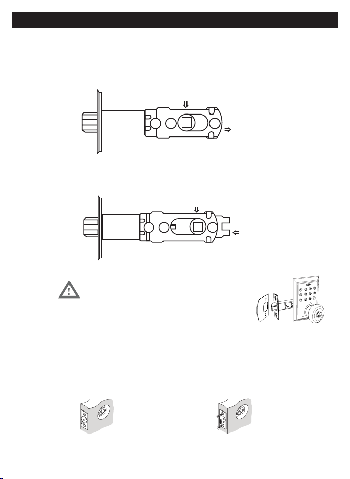
ADJUSTING AND INSTALLING LATCH
5. INSTALLING THE LATCH (need phillips head screwdriver)
mortise flush. Chisel out excess material if necessary for a flush fit (Figure 5a).
b. Using two 3/4” (19mm). screws provided, screw the latch into the door with a hand
held screwdriver. DO NOT OVER TIGHTEN (Figure 5b).
NOTE: Latch is shipped with the backset set at 23/8” (60mm)
Measure the backset (backset is distance between edge of the door and the
center of Lock).
TO CONVERT FROM 23/8” (60mm) BACKSET TO 23/4” (70mm) BACKSET
TO CONVERT FROM 23/4” (70mm) BACKSET TO 23/8” (60mm) BACKSET
PULL
PUSH
NOTE: Curved part of Latch always faces
curved portion of Strike Plate
Figure 5a
Figure 5b
23/8” (60mm)
23/4” (70mm)
4
NOTE: Tailpiece must be
positioned vertically
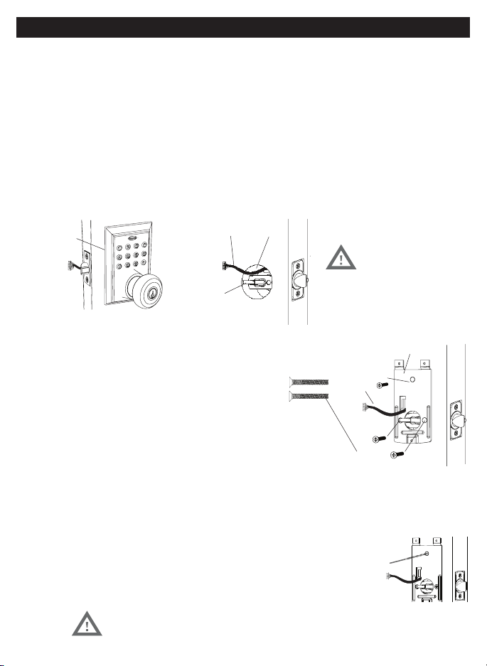
INSTALLING EXTERIOR ASSEMBLY
7. SECURING THE EXTERIOR ASSEMBLY TO THE DOOR
route the Control Wire through the rectangular
b. Place Mounting Plate against door with tailpiece passing
c. Secure the Mounting Plate to the Exterior Assembly using
d. Hand tighten with a Phillips Screwdriver leaving loosely
DO NOT OVER TIGHTEN
8. OPTIONAL INSTALLATION
a. Using a 1/16” (2mm) drill bit, drill a pilot hole in your door using the Mounting Plate
upper hole as a guide (Figure 8a).
b. Insert one 3/4” (19mm) screw and tighten.
Mounting Plate
3/4” (19mm) screw
(Optional Installation)
7/8” (22mm) screws
Control Wire
Figure 8a
Figure 7a-7f
6. INSTALLING THE EXTERIOR ASSEMBLY
remove the battery cover by sliding the cover upward. Locate the screws holding the Mounting Plate to the
a. Unpack the Exterior Assembly. Use care to not scratch the green circuit board during handling and
installation.
c. Insert the Exterior Assembly onto the door with the tailpiece going through the Latch spindle in the
VERTICAL POSITION.
Rubber
Gasket
Figure 6a-b
NOTE: Lock and unlock using the key to see if
the Latch is opening and closing easily.
Control
Wire
Tailpiece
(Vertical)
Latch
Hole
Figure 6c
5
NOTE: Tailpiece must be
positioned vertically
NOTE: Lock and unlock using Interior Knob to see if
the latch is opening and closing easily.
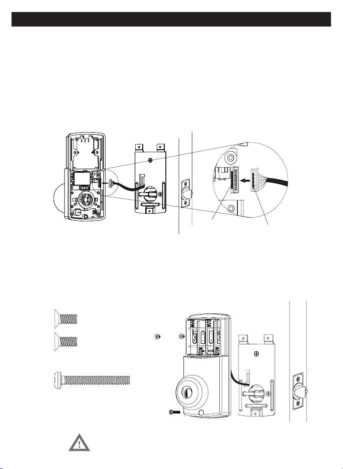
INSTALLING INTERIOR ASSEMBLY
9. ATTACH THE CONTROL WIRE TO THE INTERIOR ASSEMBLY
a. Use care to attach the Control Wire male plug to the Interior Assembly female socket connector (Figure 9a).
(Figure 9c).
connector (Figure 9d).
10. ATTACH THE INTERIOR ASSEMBLY TO DOOR
b. Using two 5/16” (8mm) screws and one 1” (25mm) screw, attach the Interior Assembly to the Mounting Plate.
DO NOT OVER TIGHTEN SCREWS
5/16” (8mm) screws
1” (25mm) screw
Figure 9a-d
Interior Wire
Connect
Plug
6
NOTE: Do not touch the Keypad until the blue light turns off.
Do not use rechargeable batteries or non-alkaline batteries.
INSTALLING INTERIOR ASSEMBLY
11. Installing Batteries
a. Insert 4 AA high quality Alkaline batteries into the Battery Compartment in the
Honeywell button will flash green twice to signify that it has received power (Figure 11a).
b. Slide the Battery Cover down into the track on the Interior Assembly to cover the batteries (Figure 11b).
12. Testing Lock
to unlock.
Override
Access Key
Exterior Assembly
Interior Assembly
Interior
Knob
Battery
Cover
Light Indicator
Keypad
Figure 11a-b
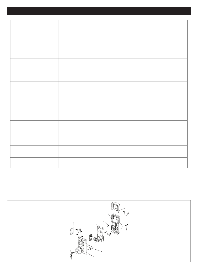
INSTALLATION OVERVIEW
Strike Plate
Battery Cover
Interior Assembly
Keys
Exterior Assembly
Rubber Gasket
Tailpiece
Mounting Plate
Latch
5/16” (8mm) screws
Optional
3/4” (19mm) screw
3/4” (19mm) screws
7/8” (22mm) screws
1” (25mm) Screw
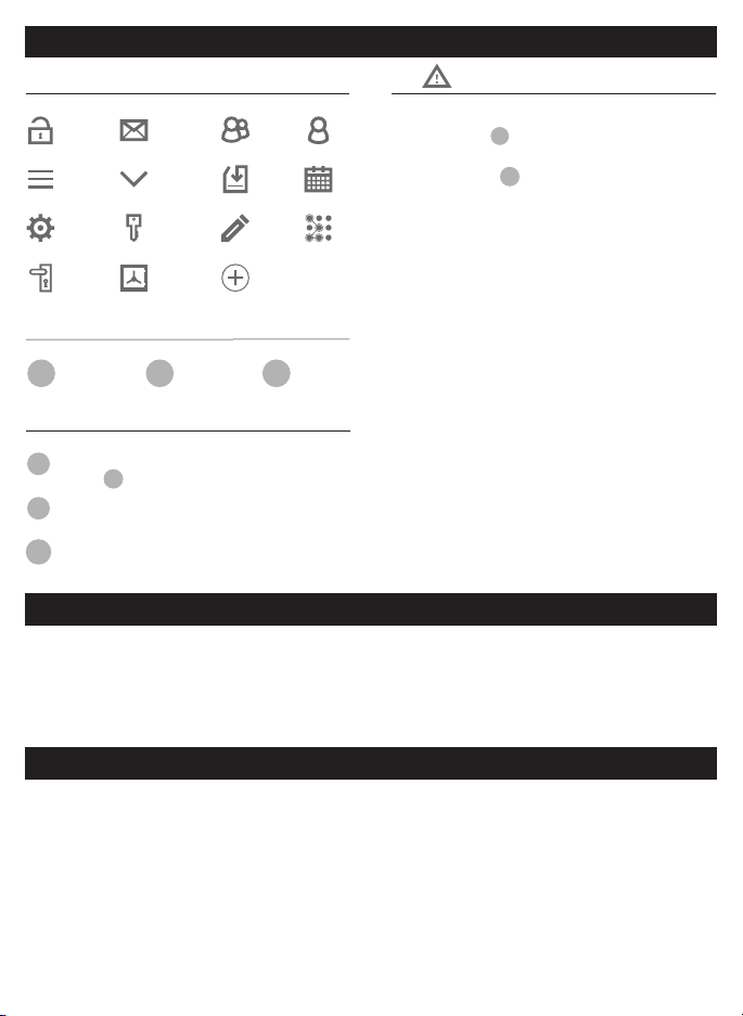
PRIMARY APP ICONS
Messages
User
Unlock
Users
Save Menu
Edit
Settings
eKey Passcode
KEYPAD SYMBOLS
USER TYPES
Administrative User
- Able to send & delete eKeys & Passcodes,
change
AP
,
and remove connected lock(s)
Authorized User
- Able to send eKeys & Passcodes, can delete
only the eKeys & Passcodes they send
User
- Able to use eKeys & Passcodes assigned from
Administrative & Authorized Users
A
AP
AU
U
After you have installed your Bluetooth Lock, download the free “Honeywell Lock” App on your smart phone
using one of the following options:
1. Search “Honeywell Lock” in the App Store or Google Play Store.
1.
3. Follow prompts on screen and enter Mobile Phone Number and Password
4. Select “Get Code”
IMPORTANT:
5. Input received verification code
6. Select “Create Account”
Administrator
Passcode
New
Passcode
NP
Passcode
RP
VERY IMPORTANT
Before connecting to a lock please
ensure that Bluetooth is enabled on
your phone and you are standing in
front of the lock, and it is activated.
App, you will have to manually lock
it. (See page 11 to set the Auto Lock
feature)
Ensure that Push Notifications are
enabled for the App.
After connecting to a new lock as
an
A
, the factory default Passcode
will be deleted, and replaced with a
new
AP
, which is randomly assigned,
and should be changed in the lock’s
settings immediately.
Locks
Safes
See page 16 for information on
features and settings for the App.
NP RP
HONEYWELL LOCK MOBILE APPLICATION INSTALLATION & USE
APPLICATION SETUP OPTIONS
REGISTER APP AND CREATE ACCOUNT

8
IMPORTANT: Your Bluetooth must be enabled and you must be within range of the lock.
3. Select which type of lock you would like to add
4. Click on available lock
5. Follow prompts to name the device
going to the “Lock Setting” page.
Go to “Lock Settings” by selecting the “Settings icon “*” in the top right corner of the screen.
SET ADMIN PASSCODE
IMPORTANT: Your Bluetooth must be enabled and you must be within range of the lock.
1. Select “Admin Passcode” from the list.
2. You will be prompted to enter your Account Password.
3.
CHANGE LOCK NAME
1. Select “Name” from the list
2.
ACTIVATE AUTO LOCK
1. Select “Auto Lock” from the list
2.
3.
4.
NOTE: Auto lock can also be programmed using the digital keypad
ADD LOCK TO GROUP
If no groups exist you will have to create one. Press “Create Group” and enter the group name.
1. Select “Group” from the list.
2.
3. Select the Group to place the lock in.
4.
UPGRADE THE CONNECTED LOCK
In order to upgrade you have to be the AP for the lock, and within Bluetooth range
that the lock is upgrading.
1. Press “Lock Upgrade” from the list to Check for Updates
2. Press “Upgrade’ (in case a pop up notification appears, follow it to finish the upgrade).
CONNECT TO BLUETOOTH LOCK
MANAGE LOCK SETTINGS

9
UNLOCK DOOR WITH THE APP
2.
LOCK DOOR WITH THE APP
1.
2. Click on the connected safe you wish to lock
3. Press and hold the lock button until the safe has locked.
AUTO LOCK
UNLOCK DOOR WITH KEYPAD
2.
LOCK DOOR WITH THE KEYPAD
1. Press the
button on the keypad.
TOUCH TO UNLOCK
IMPORTANT: Your Bluetooth must be enabled and you must be within range of the lock.
1.
3. Press any key to unlock.
USING APP TO LOCK AND UNLOCK
USING KEYPAD TO LOCK AND UNLOCK

1. Go to the Main menu by pressing the * icon at the top left corner of the screen.
2. Select “System Settings”
3. Select below settings as desired.
PATTERN PASSWORD
Create a pattern to unlock the App. Provides extra security
BEEP ON UNLOCKING
Mute or enable a sound when the door is unlocked
VIBRATION
Enable or disable the App’s vibration feature
TOUCH TO UNLOCK
MANAGE GROUPS
Assign locks to groups
WIFI GATEWAY
Connect and use the App in conjunction with an Internet Gateway
SECURITY SETTING –
Adjust the following settings
RESET LOCK VERIFICATION –
Notifications when the lock is reset
SEND EKEY VERIFICATION –
Notification when an eKey is sent
SEND PASSCODE VERIFICATION –
Notification when a Passcode is sent
DELETE EKEY VERIFICATION –
Notification when an eKey is deleted
CHANGE MANAGEMENT PASSCODE VERIFICATION –
Notification when a Passcode is changed
AUTHORIZE VERIFICATION –
Notification when a U is authorized
SYSTEM SETTINGS

11
1. Go to the Main menu by pressing the * icon at the top left corner of the screen.
2. Select “Account Management”
3. Select below settings as desired.
PROFILE PICTURE
1. Click on the picture at the top of the page
2. Change the picture associated with the account by clicking the icon
NICKNAME
1. Click on “Nickname”.
2. Enter a nickname for the account.
EMAIL/MOBILE NUMBER
1. Click on “Email”
2. Enter an email address to the account.
3. Select “Get Code”
IMPORTANT:
4. Select “Admin Passcode” from the list.
RESET PASSWORD –
1.
2.
1.
2. Select the icon at the top right of the Home screen
3. Select the message you would like to read
ACCOUNT MANAGEMENT
VIEW NOTIFICATIONS

12
CREATE & SEND PASSCODES BY EMAIL OR TEXT MESSAGE
CREATE AND SEND EKEYS
Passcodes can be sent via email or text to any SMS enabled mobile device.
SENDING PASSCODES
1. Select the lock you want to send a Passcode for
2. Select the in the bottom menu
Permanent Passcodes –
a. Select “Permanent” from the top tabs
Timed Passcodes –
b. Input the time frame
Cyclic (Recurring) Passcodes
a. Select “Cyclic” from the top tabs
b. Input the time frame
OneTime Passcodes
3. Press “Generate” to get a new Passcode
4. Input the mobile number, or email address you would like to send the Passcode to
5. Press “Send by email” or “Send by Msg.”
-
tered, or the wrong information is input when sending an eKey.
SENDING EKEYS
1. Select the lock you want to send a Passcode for.
2. Select the in the bottom menu.
NOTE:
Permanent Passcodes –
a. Select “Permanent” from the top tabs
b. Enter the receiver’s Account Name
Timed Passcodes –
b. Input the time frame
c. Enter the receiver’s Account Name
d. Press send
3. You will receive a notification once the key has been received

13
MANAGE USERS
Ensure that WiFi is connected and working in order to manage Users associated with a connected lock
FREEZE A USERS’ EKEY
1. Select the lock with the eKey you want to Freeze
2. Select the in the bottom menu
3. Select the User you would like to Freeze
4. Select “Freeze”
5. Confirm that you would like to Freeze the User
CHANGE A U TO AU
1.
2. Select the lock with the eKey you want to authorize
3. Select the in the bottom menu
4. Select the top eKey tab
5. Select the User you would like to authorize
6. Select “Authorize”
Input your account Password
8.
RENAME USERS
1. Select the lock with the eKey you want to rename
2. Select the in the bottom menu
3. Select the top eKey tab
4.
5.
6. Input the new name you would like to use
EDIT TIME FRAME
1. Select the lock with the eKey you want to edit
2. Select the in the bottom menu
3. Select the top eKey tab
4.
5. Select on the screen
6. Change the time frame for the User

14
CLEAR USER EKEYS
1. Select the lock with the eKeys you want to clear
2. Select the in the bottom menu
3. Select the top right icon
4. Select “Clear”
5. Input your account password
6. Confirm the action
RESET USER EKEYS
When you reset eKeys, all eKeys will be removed from the lock.
1. Select the lock with the eKeys you want to reset
2. Select the in the bottom menu
3. Select the top right icon
4.
5. Input your account password
6. Confirm the action
DELETE A USERS’ EKEY
1. Select the lock with the eKeys you want to clear
2. Select the in the bottom menu
3.
4. Select “Clear”
5.
6.
RENAME PASSCODES
1. Select the lock with the Passcode you want to rename/name
2. Select the in the bottom menu
3. Select “Passcode” from the top tab
4.
5.
6. Input the new name you would like to use
DELETE PASSCODES
1. Select the lock with the Passcode you want to delete
2. Select the in the bottom menu
3. Select “Passcode” from the top tab
4.
5.
6. Confirm the action
MANAGE USERS

15
MANAGE USERS
RESET PASSCODES
When you reset eKeys, all eKeys will be removed from the lock.
1. Select the lock the Passcode is associated with
2. Select the in the bottom menu
3. Select “Passcode” from the top tab
4.
5.
6. Input your account password
16
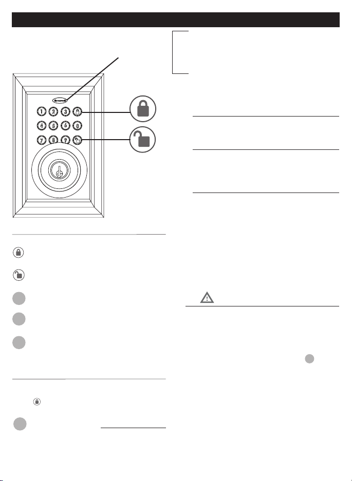
EXTERIOR ASSEMBLY OVERVIEW
Indicator light
Green
Red
l
The electronic lock requires four (4) High Quality AA
Alkaline batteries. When all 4 batteries are installed
in the correct position, you will hear 2 beeps and
the keypad will illuminate blue. DO NOT TOUCH the
keypad until the keypad stops illuminating.
Batteries (not included)
Unlock button
Lock - Use to lock door
Lock button
App in order to program the keypad.
By default the factory keypad passcode is 1234
Change the Administrator passcode
AP
so
it can easily be remembered by you after
connecting to a lock.
factory keypad passcode will be changed to
a new code, which can be found in the lock’s
settings.
Unlock - Used to unlock door
Programming - Used in programming steps
VERY IMPORTANT
Received Code (69 digits)
Complete all the programming steps in the programming mode
within 5 seconds.
Use the
key to clear entries in case a wrong button is pushed.
Programming Symbols
New Code (49 digits)
Lock / Clear
Administrator Passcode
Administrator Passcode:
AP
AP
RP
NP
(Admin Passcode is located on the Honeywell App under
Lock Settings.)
Unlock / Programming
KEY PAD PROGRAMMING OPTIONAL
The Physical Keypad is used to
lock and unlock the door, and
program functions
If you have connected the lock to the Honeywell
Lock Application, the default Passcode “1234”
will no longer work; and you will have to use the
AP
from the App, which should be changed after
connecting (see Lock Settings step 3)
3 seconds. After which the programming process
will be terminated.
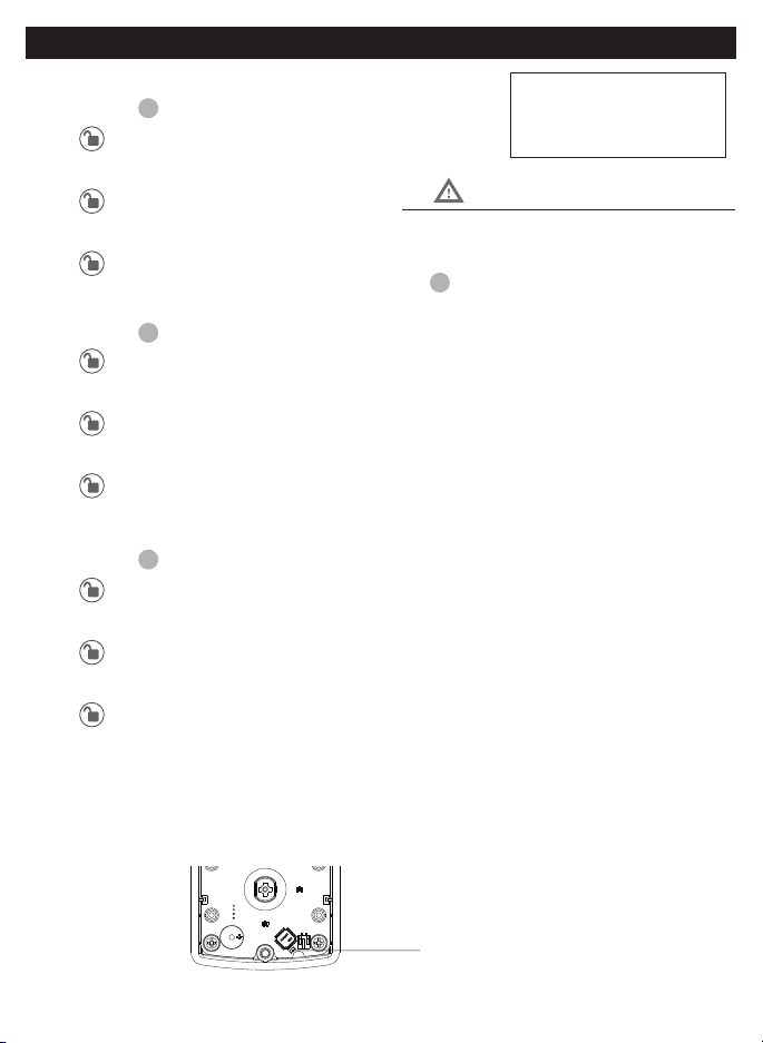
In order to access the reset button, you must
remove the batteries to remove the screws
holding the interior assembly to the door.
Batteries must be installed to activate the reset
button.
1. TURN ON/OFF AUTO LOCK FUNCTION
a. Input the
AP
b. - Green light and beep
c. 5
d.
e.
f. - Green light and beep
2. SOUND OFF
a. Input the
AP
b. - Green light and beep
c. 6
d.
e. 1
f. - Green light and beep
3. SOUND ON
a. Input the
AP
b. - Green light and no beep
c. 6
d.
e. 2
f. - Green light and beep
4. RESTORE FACTORY SETTINGS
a.
b.
VERY IMPORTANT
PROGRAMMING PHYSICAL KEYPAD
18
6. CUSTOMIZE PASSCODES RECEIVED FROM THE APP
a. Input the
AP
b. - Green light and beep
c. 1
d.
e. Input
RP
f.
g.
NP
h.
i.
NP
j. - Green light and beep
In order to change a Passcode, the Passcode
must have been sent from the App, and used by
8. VACATION MODE
a. Input the
AP
b. - Green light and beep
c.
d.
e. 1
f. - Green light and beep
9. DISABLE VACATION MODE
a. Press button for 3 seconds
b. Input the
AP
c. - Green light and beep
7. ENABLE/DISABLE AUTOLOCK
locking knob by hand to the locked position. Wait more than 2 seconds then turn the locking knob back to the
Enable - While waiting more than 2 seconds, or press the button on the keypad
5. ADD ADMINISTRATOR
connect.
VERY IMPORTANT
PROGRAMMING PHYSICAL KEYPAD
19
Issue Solution
Lock will not function
electronically.
• Check that all batteries are fresh high quality Alkaline Batteries.
• Check for proper polarity (+ -) of all batteries.
• Check that the Control Wire is attached to the Interior Assembly.
Lock gives error signal when
opening or locking and Latch
will not extend or retract
completely when closed.
• Unlock door using Key or Interior Knob.
• While door is open, check that the Latch operates smoothly.
• Check for proper alignment of the strike plate, adjust as needed to assure there is no
binding against the Latch.
The Latch is sticking. Installation screws of the lock may be too tight and have to be loosened
• Remove Interior Assembly.
• Slightly loosen the Mounting Plate screws.
• Lock and unlock using the Key.
• Reattach Control Wire and Interior Assembly.
The Keypad is not working. Application may be overriding the Keypad programming
• Check and see if the App has been connected to the lock
• Open the App and check the locks’ setting to view/change the Administrator Code
The App is unable to connect
to a lock.
Bluetooth is off, smart device is not compatible, or the lock may not be activated
• Contact customer assistance regarding compatibility issues, but iPhone 5 and later
models, and most Android devices are compatible.
• Turn Bluetooth on, and ensure the lock is activated by pressing a keypad button on the
physical lock until you see the icon to add the lock.
eKeys will not send after. • Only registered users of the App can receive eKeys.. Ensure that the whoever is receiving
the eKey has a registered account, and their information is input correctly.
• Ensure you are connected to WiFi, and that the smart device is updated.
The default Keypad Passcode
is not working
• If you have connected to the lock with the App, then the default Passcode is invalid, and
is replaced with a new Passcode generated by the App, which should be changed.
Forgotten Password • On the home screen select the Forgot Password option, then select the account type that
was registered, and follow the prompts to create a new Password.
Latch is not locking in
inclement weather
• Push or pull door to direct latch
• Re-adjust latch for smoother operations
INSTALLATION OVERVIEW
Strike Plate
3/4”(19mm) screws(C)
Mounting Plate
screw(C)
Interior Assembly
Battery Cover
5/16”(8mm) screw(A)
Latch
Exterior Assembly
Key
TROUBLESHOOTING
THEN DRILL 1” (25mm) HOLE
IN CENTER DOOR OF EDGE
2” (50mm) IN DEPTH
MARK
FOR 1-3/4”
(45mm)
DOOR
DRILL
2-1/8” (54mm)
HOLE
MARK
FOR 1-3/8”
(35mm)
DOOR
IMPORTANT!
PLACE TEMPLATE
ON HIGH EDGE OF
DOOR BEVEL
36” (915mm)
2-3/4” (70MM) BACKSET
2-3/8” (60MM) BACKSET

21
BACK OF
TEMPLATE

22
EMAIL: [email protected]
(Subject to change)
(Subject to change)
Pacific**- Local time in Los Angeles, CA, USA
* Insert correct Country Code
If you need to speak with a consumer assistant and cannot contact us during the Call
Number and the best time for us to contact you during the Call Back hours above and we will make our every
effort to contact you and help answer any of your questions or concerns.
to a replacement or refund for a major failure and for compensation for any other reasonably foreseeable loss or
damage. You are also entitled to have the goods repaired or replaced if the goods fail to be of acceptable quality
and the failure does not amount to a major failure.
CONSUMER ASSISTANCE
AUSTRALIAN CONSUMER LAW

23
Regulatory Compliance
- Federal Communications Commission (FCC)
FCC
This device complies with Part 15 of the FCC rules.
Operation is subject to the following two conditions:
(1) This device may not cause harmful interference, and
(2) This device must accept any interference, including interference that may cause
undesired operation
IMPORTANT! Changes or modifications not expressly approved by the manufacturer
could void the user’s authority to operate the equipment.
FCC COMPLIANCE

24
from Honeywell International Inc. Honeywell
International Inc. makes no representations or
warranties with respect to this product.
www.honeywellsafes.com
Manufactured by:
LH Licensed Products, Inc.
M8812309S 8812409S E V0
electronics warranty to the original residential consumer against defects in material and
workmanship under normal use as long as the original residential purchaser occupies the
residential premises upon which the product was originally installed.
the residential premises upon which the product(s) was originally installed. Proof of purchase (original sales receipt) and
ownership must accompany all warranty claims.
All non-homeowner purchasers (including purchasers for industrial, commercial and business use) are not covered under the
terms of this warranty.
product, or use contrary to or in violation of written instructions provided by LH Licensed Products, Inc. Further, this warranty
abrasions, deterioration due to the use of paints, solvents or use of cleaners containing abrasives, alcohol or other solvents,
commercial
applications, used in common area applications, disassembly, repair or alteration by anyone other than LH Licensed Products,
persons or loss of property, general damages or costs, and shipping and freight expenses required to return product(s) to
LH Licensed Products, Inc. LH Licensed Products, Inc. shall not be liable for any indirect, incidental or consequential damages
of any nature relating to this lock. LH Licensed Products, Inc. is also not responsible for costs associated with removing or
reinstalling the product.
LH Licensed Products, Inc. does not authorize any person to create for it any obligation or
liability in connection with the Product. LH Licensed Products, Inc.’s maximum liability here
under is limited to the original purchase price of the Product. No action arising out of any claimed breach of this warranty by
LH Licensed Products, Inc. may be brought by the original residential purchaser more than one (1) year after the cause of
action has arisen.
WARRANTY